
Abstract
The demand for durable, oxidation-resistant coatings for high-temperature tooling requires an understanding of intermetallic phase formation and thermal stability. Intermetallic coatings are being explored more for use in high-temperature and chemically aggressive applications. The effect of thermal treatment on Fe/Al and Ni/Al coatings deposited by thermal spraying on grey cast iron substrates was investigated with emphasis on composition, microstructure and intermetallic phase formation. Annealing experiments at different temperatures provided insight into solid state diffusion processes. During annealing, interdiffusion between the coating and substrate components led to the formation of homogeneous intermetallic phases on the surface. The results showed that both chemical composition and annealing parameters influence the hardness of thermally sprayed coatings. Temperature and duration were found to have a significant effect on intermetallic phase formation. For Fe/Al coatings, annealing at 700°C resulted in the formation of FeAl and Fe3Al intermetallic compounds, whereas at 1000°C only the FeAl phase remained. In Ni/Al coatings, annealing at 700°C resulted in the formation of multiple phases, including Ni3Al, NiAl, and Ni2Al3, while at 1000°C only the NiAl phase was present. Optimization of thermal treatment processes can significantly improve the mechanical and chemical properties of coatings, making them suitable for a wide range of applications in industries.
Introduction
Electric arc spraying is a widely employed process for the protection of ferrous materials, aiming to enhance service life and performance. Compared to other thermal spraying techniques such as plasma spraying, arc spraying offers several advantages including high deposition efficiency, ease of operation, and relatively low equipment costs.1,2 By utilizing pre-alloyed or core wires filled with powder, intermetallic and alloy coatings can be fabricated through an electric arc spraying process. Moreover, spraying different wires simultaneously allows the development of coatings with superior properties when compared to the substrate without coating. 3 These coatings combine desirable qualities of two different materials, resulting in enhanced performance. 4 Various studies have investigated the deposition of coatings using arc spraying processes, for example stainless steel/Al and Ti/Al systems3,5 It focuses on the effects of thermal treatment on Fe/Al and Ni/Al coatings applied by thermal spraying to gray cast iron substrates. It provides new insights into how annealing temperature and duration affect intermetallic phase formation, microstructure and mechanical properties. The coating is highly relevant for industry as it significantly enhances the performance of low-cost materials, making them suitable for demanding applications. These coatings show great promise in extending the service life of metallic tooling that is in direct contact with molten glass.
Intermetallics represent a distinct category of materials that possess a unique combination of metallic and ceramic properties. Unlike conventional disordered alloys, intermetallics exhibit an ordered atomic arrangement. Within an intermetallic structure, atoms are interconnected through a combination of metallic contributions, as well as covalent/ionic bonds, in contrast to the predominantly metallic bonding in conventional non-ordered alloys.6,7
Nickel and iron aluminides, distinguished by their substantial aluminum contents and elevated melting points, offer exceptional resistance to oxidation at high temperatures ranging 1100°C up to 1400°C, as in the case for NiAl. 8 Figure 1 shows the binary phase diagram of the Ni/Al-system. The Ni/Al system contains five intermetallic phases. Among these, the β-NiAl phase is characterized by a wide range of compositional stability, high elastic stiffness, relatively low density and exceptional oxidation resistance at temperatures above 1300°C. 9
Fe-based intermetallic alloy materials, specifically FeAl, have gained significant attention due to their favorable wear and corrosion properties at high temperatures. 10 Iron aluminides have become a preferred choice over stainless steel and other superalloys due to their lower densities. In comparison to nickel aluminides iron aluminum system have reduced costs, attributed among other factors to the abundance of raw materials. 11 Figure 2 shows the binary phase diagram of the Fe/Al-system. The Fe/Al system contains the following equilibrium phases 12 : Fe/Al melt, a solid solution of aluminum in bcc iron, a solid solution of iron in fcc aluminum, the ordered solid solutions Fe3Al and FeAl, and the intermetallic compounds FeAl2, Fe2Al5 and FeAl3. At elevated temperatures (1002–1232°C), the ε-Fe5Al8 phase 13 and the solid solution of aluminum in fcc iron remain stable. Fe3Al and FeAl, which have a high iron content, continue to offer oxidizing resistance, as well as good tribological and strength properties.14–16
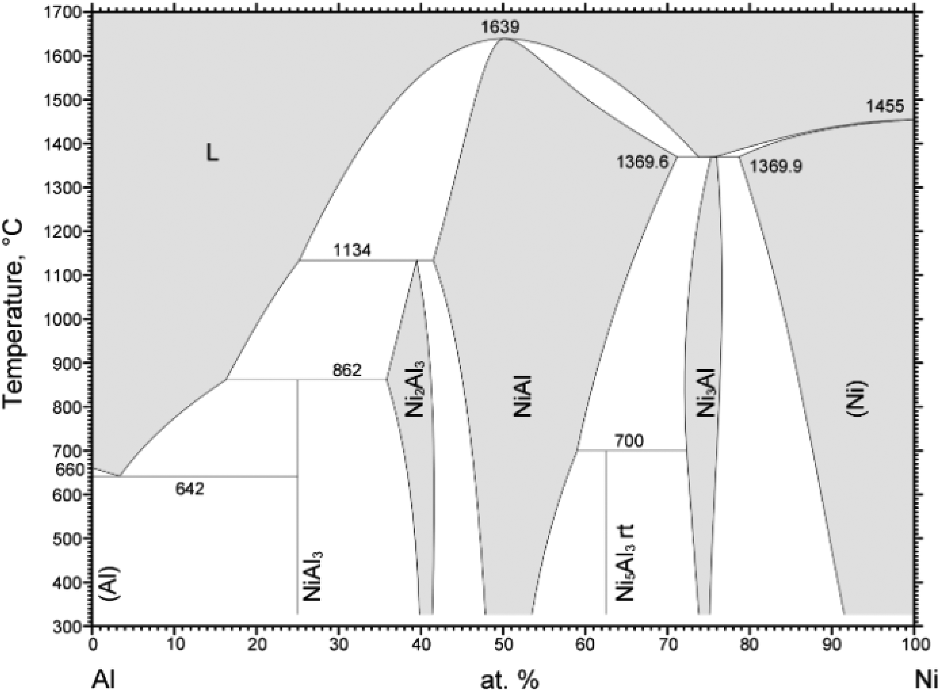
Binary phase diagram of Ni/Al 48 .
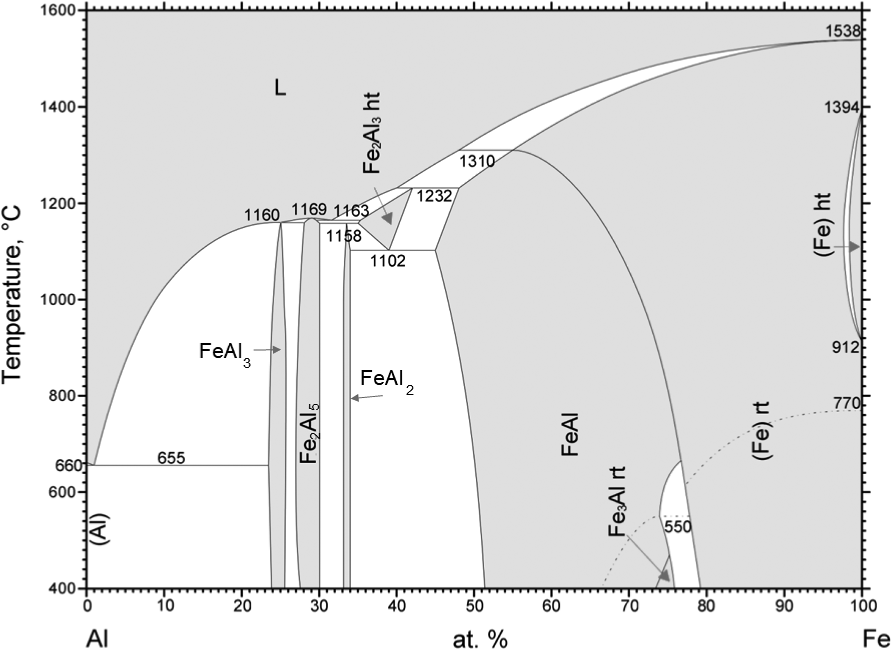
Binary phase diagram of Fe/Al 12 .
While the deposition process plays a crucial role, post-treatment techniques can further enhance the properties of coatings. Previous research explored the effects of heat treatment on the properties of arc-sprayed Mg-Al, Fe-Al, and Al coatings, demonstrating improvements in microhardness, cohesion strength, oxide composition, elemental diffusion, and bonding strength.17–20 However, limited attention has been given to the microstructure and mechanical properties of Ni-Al and Fe-Al coatings applied with electric arc spraying after different heat treatments.
This study aims to investigate the chemical composition of Al-based alloy coatings after different heat treatments and evaluate the impact of the formed intermetallic compounds on coating performance. Studying the changes of microstructure and mechanical properties of these coatings after various heat treatments provides a comprehensive understanding of the materials and their behavior at elevated temperatures.
Materials and methods
Three wires, Aluminum (>99 wt.% Al., <1 wt.% Cr), Iron (97.57 wt.% Fe, 1.45 wt.% Mn, 0.9 wt.% Si, 0.08 wt.% C) and Nickel (>99 wt.% Ni), were selected for thermal spraying. Aluminum wires with two diameters (2.0 mm, 1.2 mm) were used in combination with a 1.0 mm iron wire and a 1.6 mm nickel wire, respectively. For wire arc spraying Fe or Ni wire served as the anode, while the Al wire as the cathode. The coating was deposited onto lamellar grey cast iron sheet substrate (EN GJL-250) measuring 50 mm × 40 mm × 5 mm. Prior to the spraying process, the substrate was sand blasted with corundum particles to enhance the adhesion between the substrate and the coating. The surface was then cleaned using ethanol.
Figure 3 shows the fabrication of the specimen using System Model 9935 CoArc arc spraying equipment from Praxair. The arc-spraying process uses an electric arc at the tip to melt wires, and the resulting molten or semi-molten material is propelled onto a sandblasted substrate with a surface roughness of Ra = 3.5 ± 0.3 µm by a high-velocity gas stream, forming a coating. The arc-spraying system typically consists of a compressed gas supply, a wire feed mechanism, an arc-spray gun, a spray controller, and a power supply. The process parameters are at 50 A, 28 V, 300 kPa at a spray distance of 150 mm, N2 as process gas and substrate temperature at room temperature were maintained.
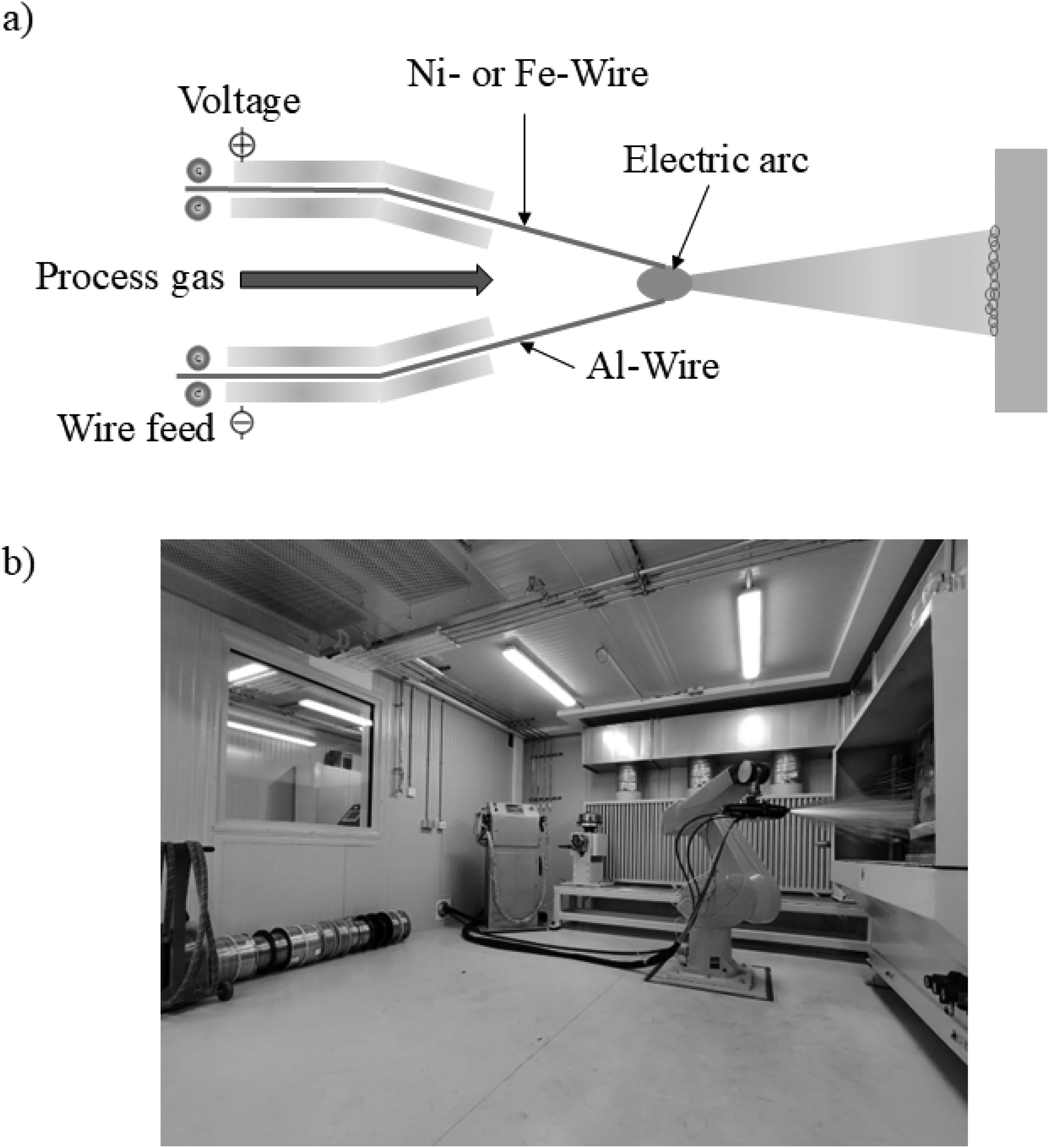
a) Schematic diagram of the electric arc spraying process, b) Thermal spray process facility at Neue Materialien Bayreuth GmbH, Bayreuth, Germany.
The heat treatment process was designed to investigate the effects of temperature and duration on the microstructure and elemental diffusion of the material. Three different heat treatments were used: first, the samples were held at 700°C for 1 h, a temperature below the critical eutectoid transformation point of 723°C, which is significant for the grey cast iron substrate. The second heat treatment involved an extended heat treatment at 700°C for 64 h. This prolonged exposure below the critical temperature allowed for gradual diffusion of alloying elements and a more uniform microstructure. In the third heat treatment, the samples were heated to 1000°C for 16 h to accelerate the diffusion processes. This higher temperature provided sufficient thermal energy to promote significant atomic mobility, enhancing the redistribution of elements and enabling phase transformations.
Cross-sections were prepared using metallographic methods: cutting, mechanical grinding and polishing. The polished surfaces were examined using optical microscope (Zeiss Axioplan 2, Zeiss, Germany). Digital micrographs were taken with an Olympus CCD. In addition, a scanning electron microscope (Zeiss 1540 XB, Zeiss, Germany) equipped with energy dispersive spectroscopy (EDS) was used to obtain information about the chemical composition. X-ray diffraction (XRD) analysis was conducted to determine the phases of the coatings using a Bruker D8 Discovery A25 diffractometer from Bruker AXS GmbH with monochromatic Cu KαI radiation. The samples were scanned from 40° to 90° with a step size of 0.02°. Each step had 0.5 s X-ray acquisition time.
Evaluation of the coating porosity involved analyzing cross-sectional images using ImageJ software. Up to ten scanning electron microscopy (SEM) images were taken to calculate the average porosity of the coatings.
The Martens hardness (HM) of the samples was measured using a Fisherscope HM2000 microhardness tester from Helmut Fischer GmbH. Samples were prepared with grinding and polishing to achieve a flat, smooth, and clean surface. Measurements were performed with a maximum load of 0.1 N and a test duration of 5 s. Force-depth curves were recorded during loading and unloading, and the Martens hardness was calculated automatically. Multiple measurements were taken across each sample, and the average values with standard deviations were reported.
Results and discussion
Figure 4(a) shows a cross-section micrograph obtained by SEM in secondary electron mode (SE) of an as-sprayed Ni/Al coating. The cross-sectional morphology consists of a layered structure of alternating splats appearing light grey (marked A) and dark grey (marked B) forming a coating. Spray coating defects, such as pores and the inclusion of oxides within the coating are present. The selected spraying parameters result in coatings thicknesses ranging from 100 µm to 300 µm reaching up to 400 µm, with individual splat thicknesses between 10 µm and 20 µm. Visual inspection of the cross-section indicates that the as-sprayed coatings adhere well to the grey cast iron substrate. Figure 4(b) shows EDS mapping of Ni and Al on the cross-section of the as-sprayed Ni/Al-coating. This analysis shows, that the light grey area, marked A in Figure 4(a) is rich in Ni with a nickel content of 94 ± 3 at.%, whereas the dark grey area (marked B) is composed 95 ± 5 at.% Al. Figure 5 shows the interface between an Ni splat of the Ni/Al coating and the grey cast iron substrate, as depicted in Figure 4(a). Stresses developed at the interface between the substrate and the coating due to the difference in thermal expansion coefficients during cooling. The coefficient of thermal expansion of the substrate material is approximately 10–20% lower than that of the coating materials (nickel, iron and aluminium).21,22 These thermal stresses contributed to the formation of microcracks in the interfacial region. Additionally, oxide inclusions were identified, which can be attributed to the oxidation of molten metal particles during flight and upon impact. This is the result of their exposure to ambient oxygen during the thermal spraying process.
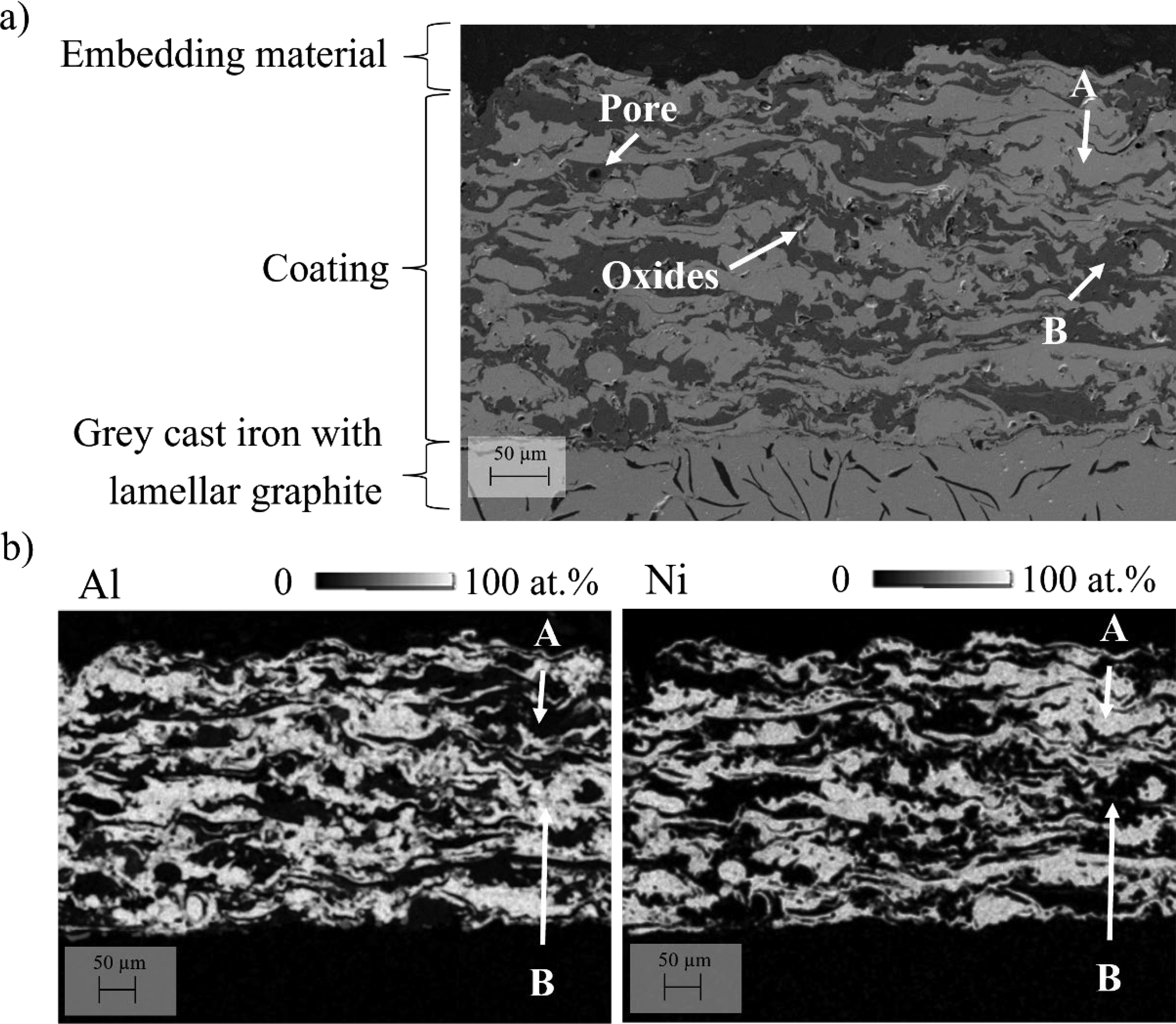
a) SEM images in SE mode of the cross-section of an as-sprayed Ni/Al-coating, b) EDS quantitative element mapping of Ni and Al on the cross-section of an as-sprayed Ni/Al-coating. Point A indicates Ni-rich regions, while point B corresponds to Al-rich areas.
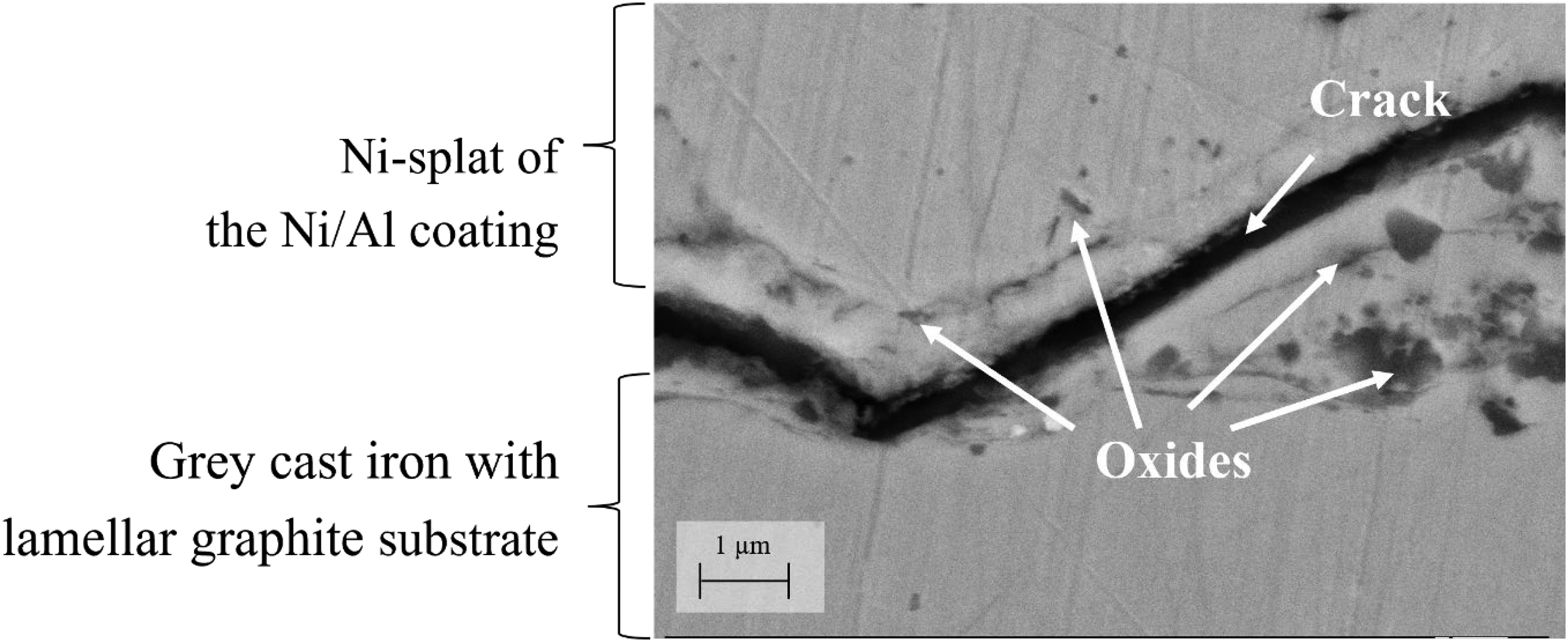
SEM images in SE mode of the cross-section of the interface of the as-sprayed Ni/Al-coating.
Figure 6(a) shows the cross-section of the as-sprayed coating from the Fe/Al system, which also has alternating splats, with some appearing light grey (marked C) and others dark grey (marked D). Analogue to the Ni/Al-system the Fe/Al-coating has similar defects, such as pores and oxide inclusions. The resulting coating thickness is also in a similar range as the Ni/Al counterparts between 100 to 300 µm. The thickness of the splats is between 10 µm and 20 µm. Based on the visual analysis of the cross-section, the as-sprayed coatings have good adherence to the grey cast iron substrate.
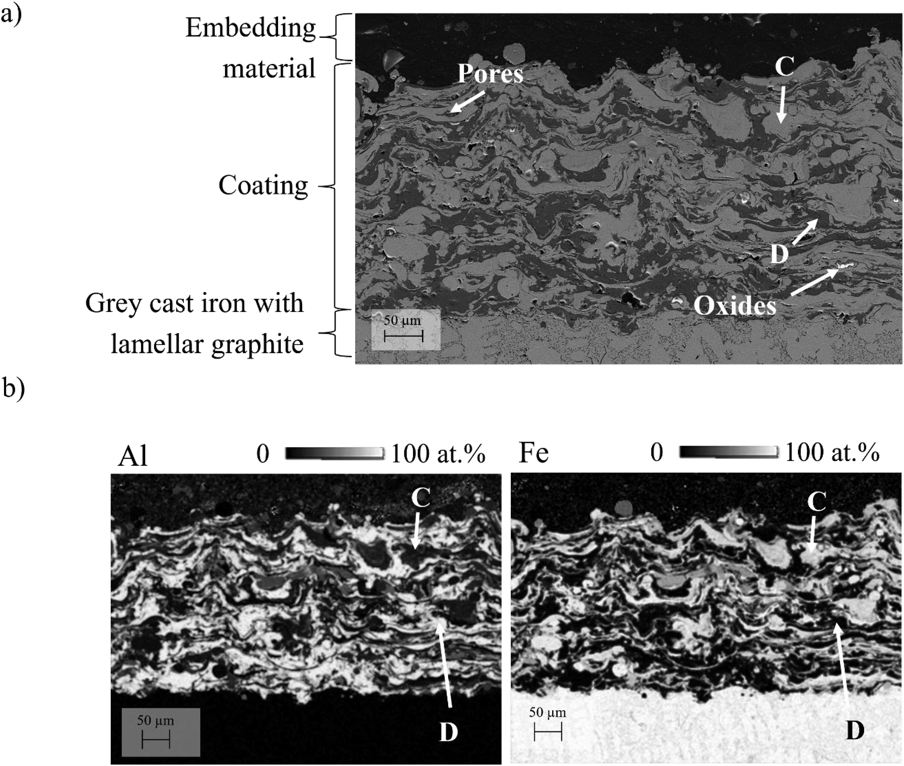
a) SEM images in SE mode of the cross-section of an as-sprayed Fe/Al-coating, b) EDS quantitative element mapping of Fe and Al on the cross-section of an as-sprayed Fe/Al-coating. Point C indicates Fe-rich regions, while point D corresponds to Al-rich areas.
Figure 6(b) shows EDS mapping of Fe and Al on the cross-section of the as-sprayed Fe/Al-coating. In comparison to Figure 2(b) the light grey area (marked C) was found to be enriched with Fe (95 ± 6 at.% on average). The dark grey area (marked D), on the other hand, consists of 96 ± 1 at.% Al.
Figure 7(a) shows the microstructure and Figure 7(b) the EDS element mapping results on the same area in the Ni/Al-coating after being heat-treated at 700°C for 1 h.
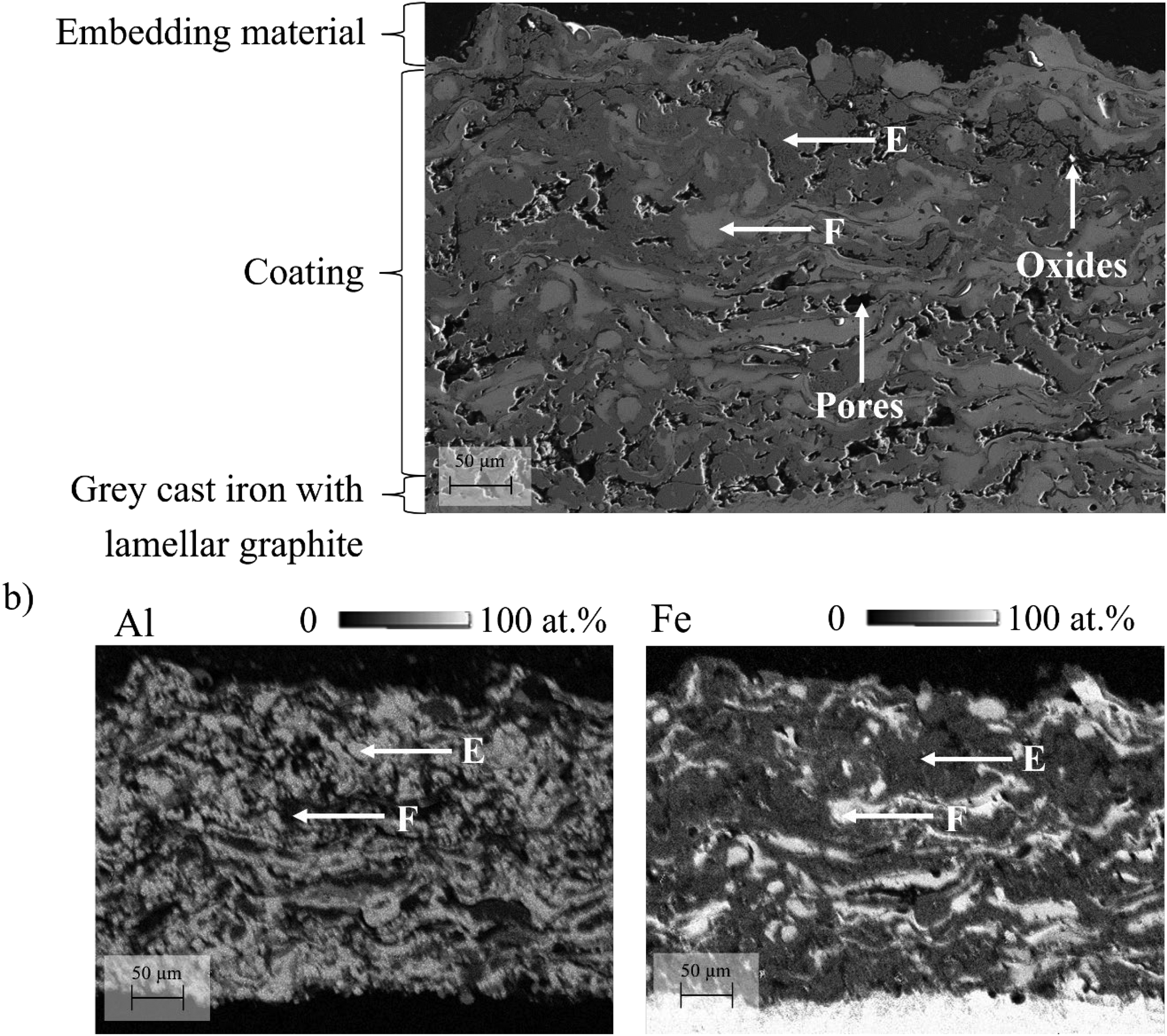
a) SEM micrograph in SE mode of the cross-section of the Fe/Al-coating treated at 700°C for 1 h, b) EDS element mappings of Al and Fe on the same area of the sample. Point E indicates Al-richer regions, while point F corresponds to Fe-richer areas.
In detail, the dark grey area (marked E) is predominantly composed of Al, while the light grey area exhibited (marked F) Ni-rich splats. Diffusion takes place and results in a reduced concentration gradient. The average Al in the dark grey area is 64 ± 4 at.%, whereas the Ni content in the light grey area is at an average of 78 ± 3 at.%. These variations point toward the formation of distinct intermetallic phases, which can be confirmed by correlating with phase diagrams and are relevant for mechanical performance and oxidation resistance.
Figure 8(a) shows a SEM micrograph in SE mode of the cross-section of the Ni/Al-coating after heat-treatment at 700°C for 64 h. While the SE image shows only slight differences in grey scale, the image obtained in backscattered electron mode (BSE) in Figure 8(b) at a higher magnification together with the point analysis and line scan results (Figures 8(c) and 8(d), respectively) showing differences in the elements distribution Within the analyzed areas (marked by the letters from G to M in Figure 8) Ni and Al contents vary significantly. While the areas marked by G and M contain 57 at.% and 56 at.% Al respectively, the area marked with K contains as much as 64 at.% Ni. The areas marked by H, I and L have more similar content of both elements. These results suggest that different Ni/Al phases might have been formed during the heat treatment at 700°C for 64 h.
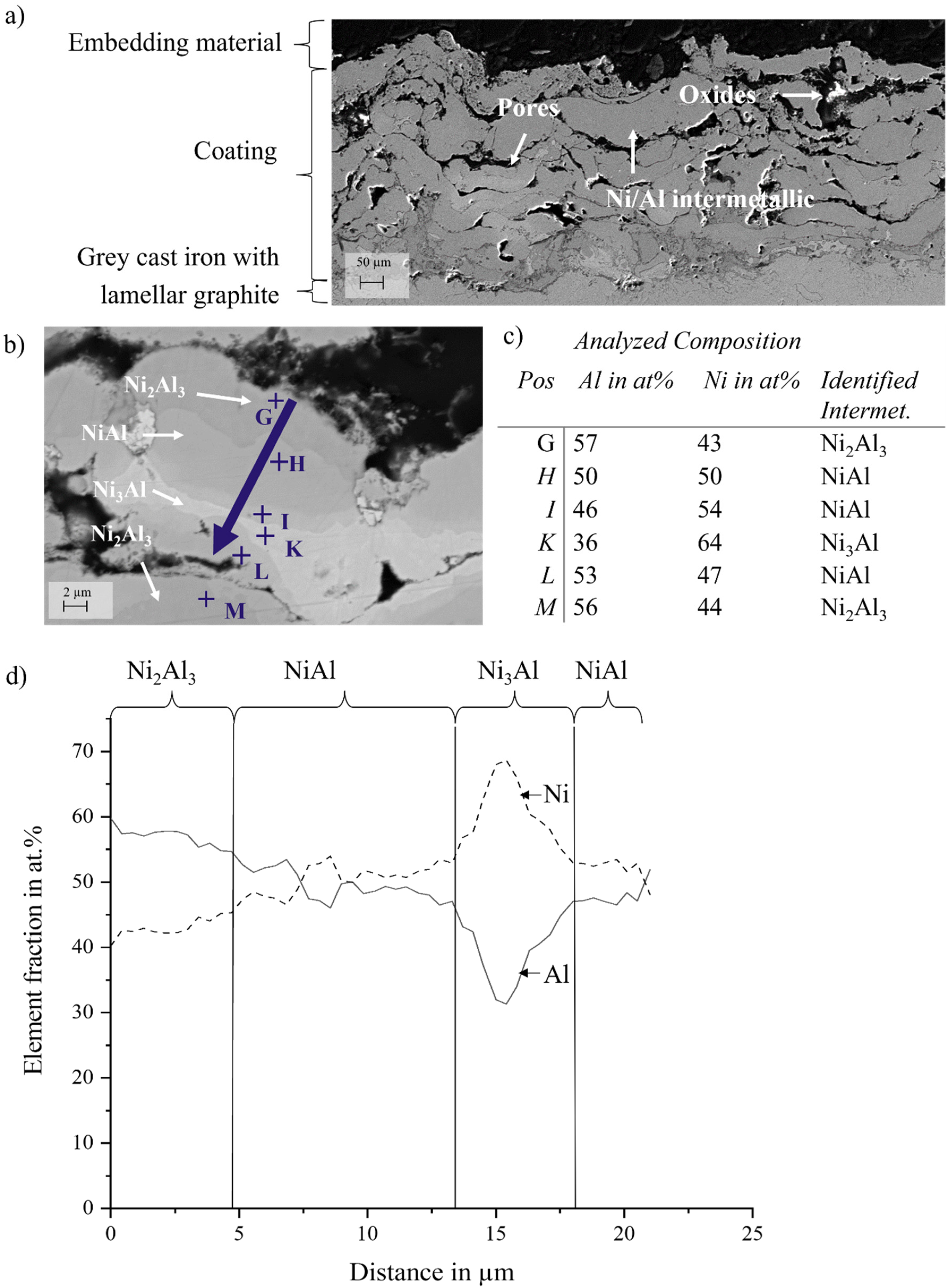
SEM images of the Ni/Al-coating after treatment at 700°C for 64 h in a) SE mode b) in BSE mode; chemical composition of the different regions according to EDS by c) point analysis, and d) line scan.
Figure 9(a) shows the cross-sectional micrograph of the Ni/Al-coating after annealing at 1000°C for 16 h obtained by SEM in SE mode. After annealing under these conditions, the coatings have a single phase homogeneously distributed. Figure 9(b) shows the quantitative element distribution of the same area shown in Figure 9(a). The coating is composed of 53 ± 2 at.% nickel and 47 ± 1 at.% aluminum.
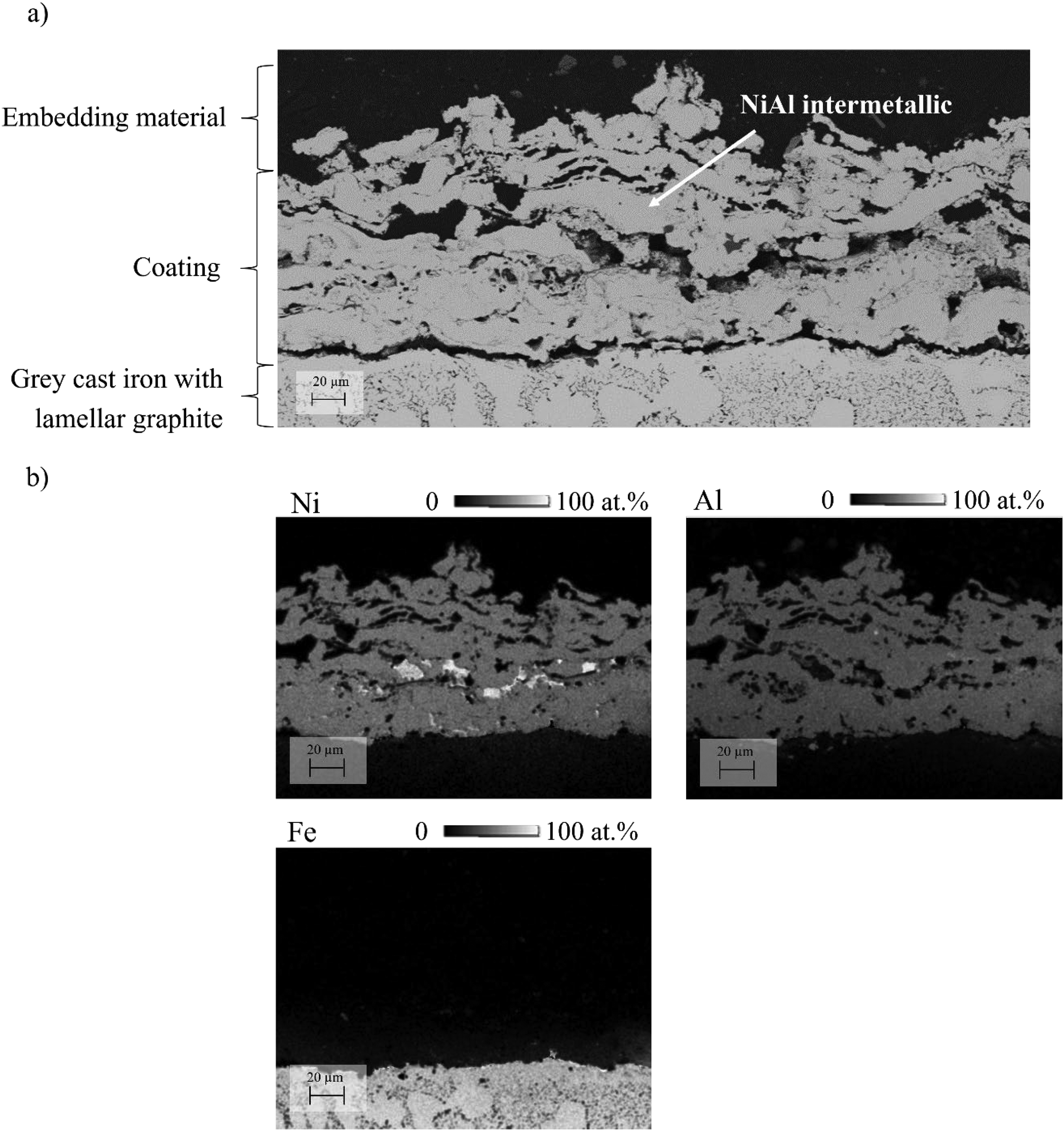
a) SEM image in SE mode of the cross-section of a Ni/Al-coating heat-treated at 1000°C for 16 h, b) EDS analysis as quantitative element mapping of Ni, Al and Fe.
Figure 10(a) shows the cross-sectional SEM micrograph in SE mode of a Fe/Al-coating after annealing at 1000°C for 16 h. Similar to the Ni/Al-coating after annealing under the same conditions, only one phase can be identified. Figure 10(b) shows the quantitative distribution of elements in the same region as depicted in Figure 10(a), with the composition consisting of 51 ± 1 at.% iron and 49 ± 1 at.% aluminum. The element distribution also shows the diffusion of aluminum into the grey cast iron substrate.
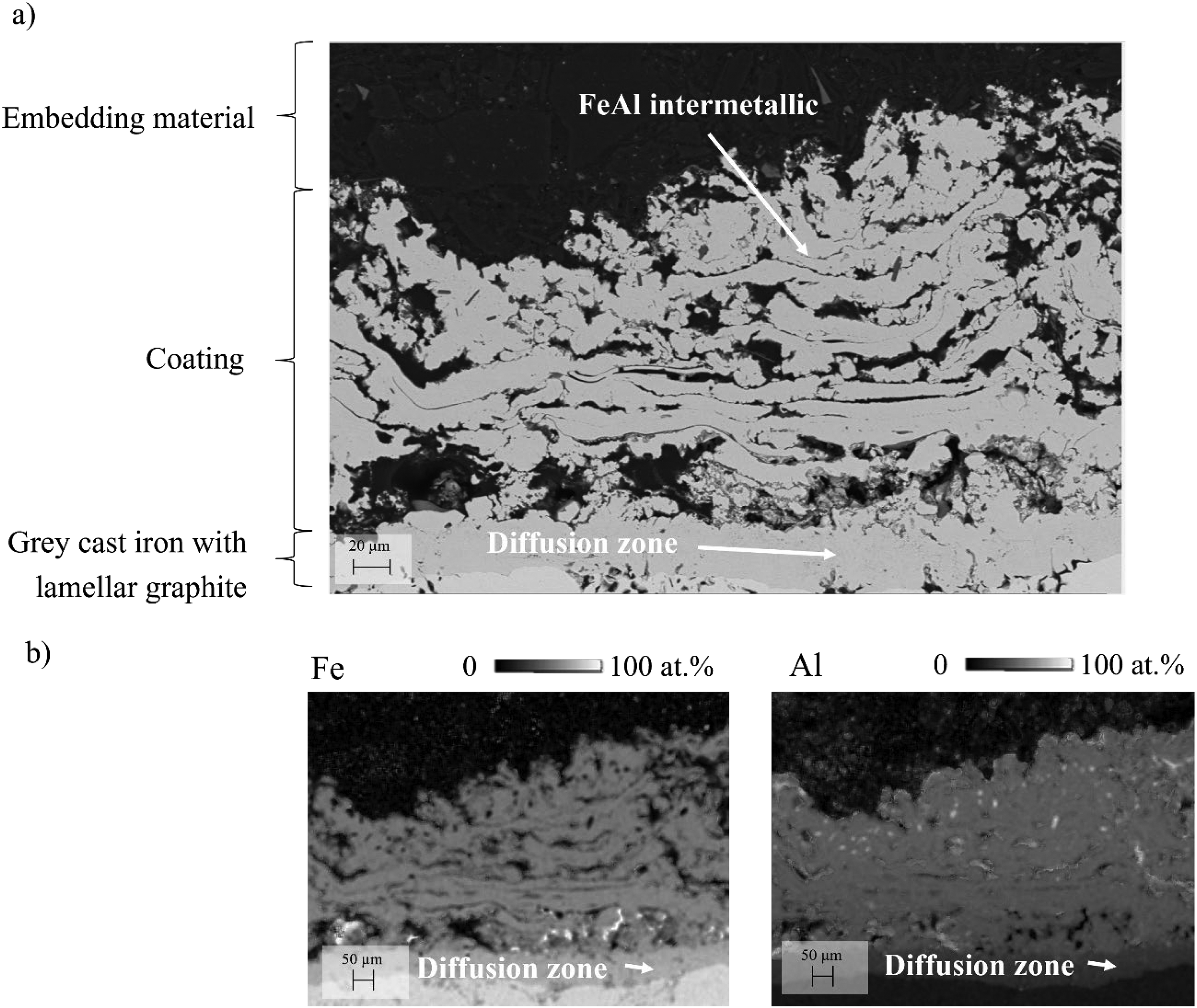
a) SEM image in SE mode of cross-section of a Fe/Al-coating after treatment at 1000°C for 16 h, b) EDS analysis as quantitative element mapping of Al and Fe.
Figure 11 shows the XRD spectrum of the Ni/Al coating in the as-sprayed condition as well as after heat treatment at 700°C for 1 h, at 700°C for 64 h and at 1000°C for 16 h.

X-ray diffraction patterns of the Ni/Al coating in the as-sprayed condition and after heat treatments at 700°C for 1 h, 700°C for 64 h, and 1000°C for 16 h.
Figure 12 shows the XRD pattern for the same conditions in Fe/Al-System.
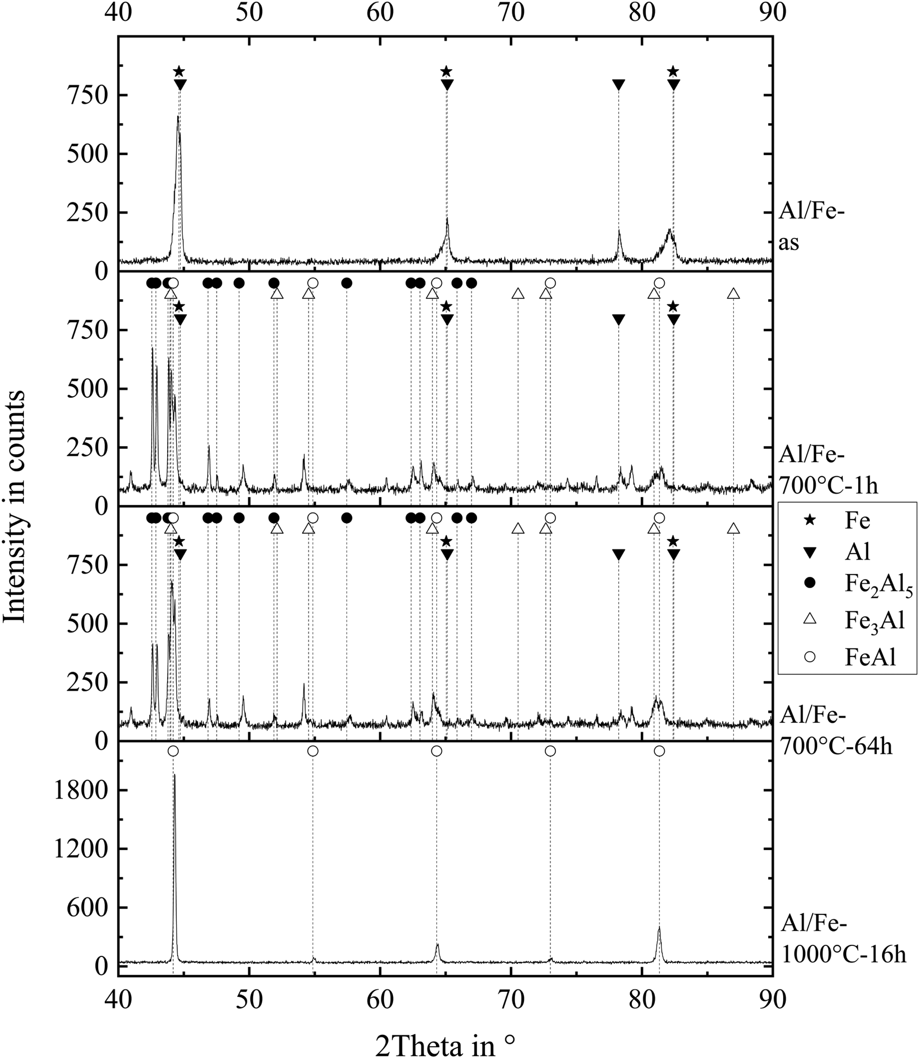
X-ray diffraction patterns of the Fe/Al coating in the as-sprayed condition and after heat treatments at 700°C for 1 h, 700°C for 64 h, and 1000°C for 16 h.
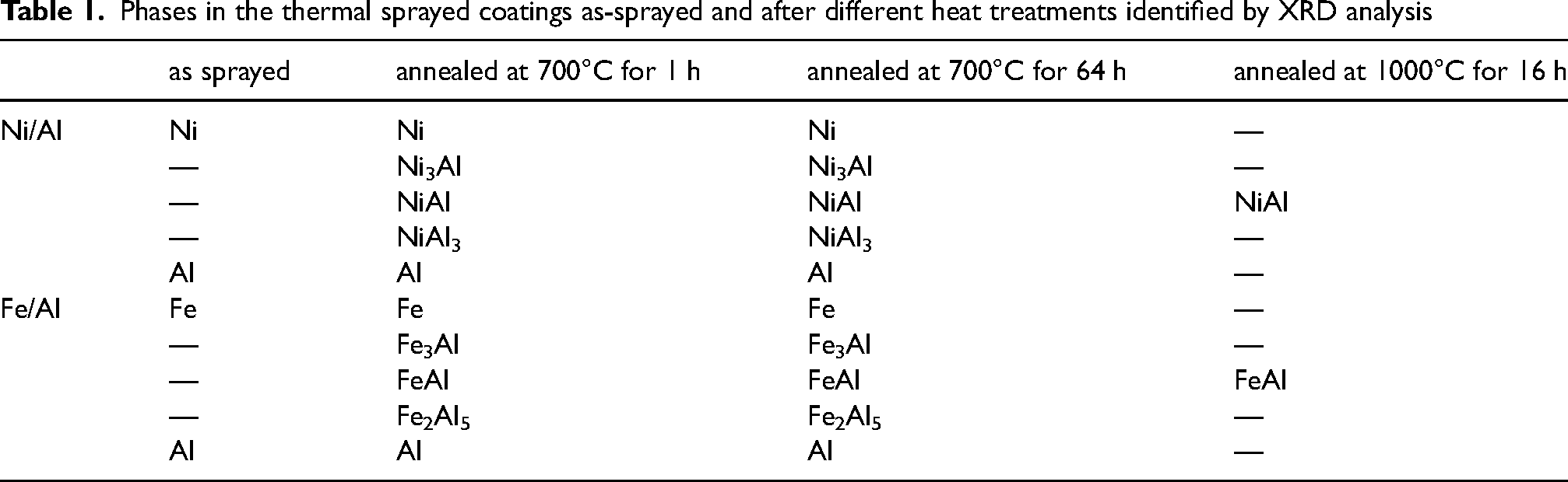
Table 1 lists all phases detected by XRD.
Phases in the thermal sprayed coatings as-sprayed and after different heat treatments identified by XRD analysis
The microstructure of the as-sprayed coatings analyzed by SEM, showing a lamellar structure containing light and dark grey areas, is typical for an electric arc sprayed coating with more than one material. 23 The boundaries of these areas are clearly distinguishable. Boundaries between splats are visible in the cross-sectional micrographs. This is a characteristic feature of thermal spray coatings, resulting from the irregular overlap of metal droplets. 24 EDS analysis shows that the light grey area is enriched in nickel for the Ni/Al coating and iron for the Fe/Al coating, while the dark grey area is aluminum rich. In electric arc spraying, the splats are formed when the molten tip of each wire is propelled towards the substrate surface. As the tips are not in contact, the molten metal droplets formed from one wire have minimal contact with the droplets from the other wire until the droplets hit the substrate, where they cool rapidly, preventing diffusion. 25
Posterior heat treatment of the coatings was used to enable diffusion, aiming at the formation of intermetallic phases. Diffusion processes show an exponential dependence with the temperature, as described by the Arrhenius equation. This occurs due to the heightened kinetic energy of particles when the temperature increases. Moreover, since diffusion processes are time-dependent, the duration of the heat treatment is relevant for the formation of different phases. 26 Above the melting point of aluminum, the reaction mechanisms are determined by the formation of NiAl3. With increasing temperature, the mobility of the Aluminum atoms increases, resulting in a faster formation of the intermetallic phase. Solid phase diffusion of the nickel atoms then leads to the formation of Ni2Al3. 27 Through continuous diffusion of further nickel atoms, the amount of Ni2Al3 continues to increase, while that of NiAl3 decreases. Subsequently, the diffusion of additional nickel atoms into the Ni2Al3 phase leads to formation of NiAl. Finally, Ni3Al is formed by further diffusion of nickel.28,29
During temperature-induced diffusion, the formation of FeAl and Fe3Al intermetallic compounds takes place at low temperatures and short times. 30 These phases arise from the Fe2Al5 phase, which is firstly formed, due to its faster nucleation and growth compared to FeAl, FeAl2, and FeAl3.31,32 The transformation into the FeAl phase is governed by the diffusion of Fe atoms into the Fe2Al5 layer at elevated temperatures. 16 When the melting point of aluminum is surpassed, Al diffuses into Fe, forming the Fe2Al5 phase and, subsequently, the FeAl and Fe3Al intermetallic phases. 33 This reaction becomes dominant at temperatures around 1000°C, whereby a single-phase FeAl structure can form after a few hours. 34
In the Ni/Al and Fe/Al binary systems, the formation of intermetallic phases during heat treatment is accompanied by distinct changes in the crystalline structure, as reflected in the lattice parameters. In the Ni/Al system, the most commonly observed phases are NiAl (B2 structure), Ni₃Al (L1₂ structure) and Ni₂Al₃ (orthorhombic). NiAl has a cubic B2 structure with a lattice parameter of around 2.88 Å, whereas Ni₃Al has a slightly larger lattice parameter of approximately 3.56 Å due to its L1₂ ordered structure. 35 Ni₂Al₃ crystallizes in an hexagonal structure with reported lattice parameters of approximately a = 4.04 Å and c = 4.88 Å. 36 These structures contribute to the improved hardness and oxidation resistance observed after annealing. In the Fe/Al system, FeAl crystallises in a B2 structure with a lattice parameter close to 2.90 Å, similar to NiAl. In contrast, Fe₃Al adopts a DO₃ structure with a lattice parameter of around 5.78 Å. Fe₂Al₅ forms an orthorhombic structure with typical lattice parameters of a = 7.67 Å, b = 6.40 Å and c = 4.20 Å. 37 The XRD reflex positions and intensities measured in this study are in good agreement with the known lattice parameters of these intermetallic phases. The presence of reflex confirms the successful formation of these ordered phases after annealing. The absence or significant reduction of signals associated with pure Ni, Fe or Al after heat treatment at 1000°C for 16 h indicates that the interdiffusion process is complete. Slight shifts in the positions of some of the peaks suggest the presence of residual stresses or minor deviations in the stoichiometry of the formed phases. These could be caused by non-uniform diffusion or local compositional gradients within the sprayed coatings.
The coating also contains oxygen in the form of oxides. During the spraying process, molten droplets experience oxidation in-flight, upon impact, and after deposition onto the substrate. The presence of oxide layers separating the sprayed deposits inhibits the formation of intermetallic phases in the as-sprayed coatings by acting as diffusion barriers. 38 The presence of pores in the coatings is due to partially melted particles, which can’t achieve full deformation, and the entrapment of gas within the molten droplets during solidification.2,39
Figure 13 shows the results of the microhardness tests. The plotted values represent the average of fifteen measurements taken across the entire thickness of the coating. Significant variation in hardness was observed depending on the specific area of the coating. The as-sprayed coating exhibited lower Martens hardness compared to the annealed coatings. In terms of absolute values, the microhardness of the Ni/Al coatings was slightly higher than that of the Fe/Al coatings.
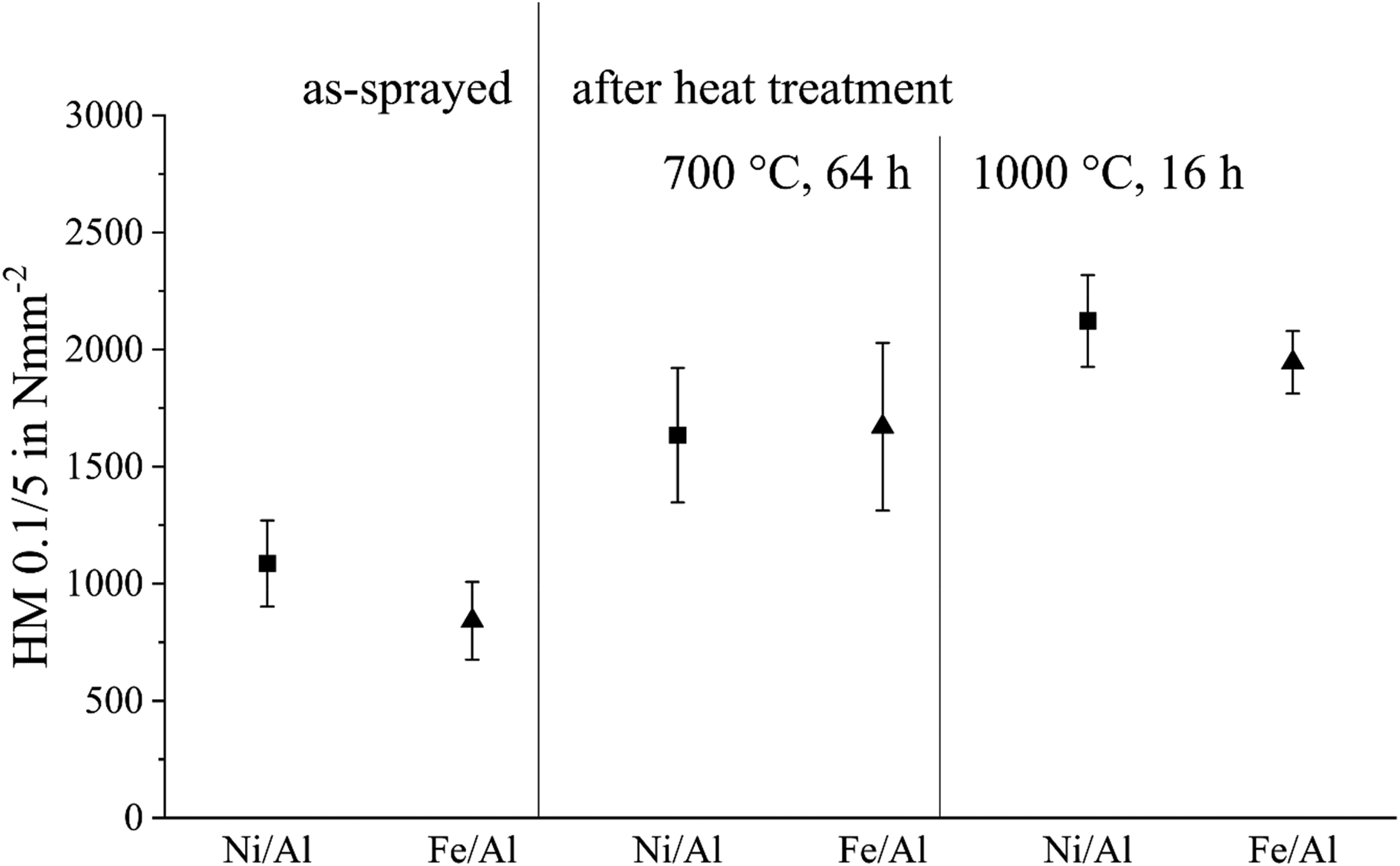
Microhardness of the cross-section of the as-sprayed coatings and the annealed coatings.
An increase in microhardness occurs during annealing of the as-sprayed coatings. This is consistent with the results of the SEM/EDS and XRD analyses, which evidenced the formation of intermetallic phases. In contrast to co-electrodeposited Ni–Al composites, in which the addition of aluminium reduced hardness due to the presence of ductile particles and weak interfacial bonding, the thermal spraying process investigated here led to the formation of an intermetallic phase and subsequent hardening during annealing. 40 Existing literature on the hardness of intermetallic phases describes that the intermetallic phases have greater hardness compared to the constituent elements. 41 Therefore, the formation of intermetallic phases is the cause of the increase in hardness values. The hardness of the Ni/Al intermetallic phases is between 1.5 to 6 times higher than the hardness of Ni and 6 to 20 times higher than the hardness of Al.42–44 Analogue for the Fe/Al-systems, which according to the available literature can form intermetallic phases with hardness values 1.5 to 8 times higher than the value for Fe and 6 to 27 times higher than the value for Al.45–47 As the intermetallic phases in the coating are unevenly distributed, this results in a high standard deviation in heat treated samples. At 1000°C, the intermetallic phase in the coating is more homogeneous, which means that the scatter of the individual measuring points is less.
Conclusions
Coating applicated with electric arc spraying can significantly improve the properties of low-cost materials, making it ideal for a wide range of industrial applications. This process using two different wires is a powerful tool to produce intermetallic coatings on grey cast iron. This process Coatings with thicknesses between 100 µm and 300 µm were applied onto grey cast iron. Coatings composed of Ni and Al as well as Fe and Al were sprayed, and heat treated under different conditions. These coatings were characterized by elemental distribution, formed phases and hardness. The microstructure of the as-sprayed coatings is composed of clusters of individual metals, due to the lack of mixing and interdiffusion during spraying. For the formation of intermetallic phases, e.g., NiAl (50:50 at.%) and FeAl (50:50 at.%), heat treatment was necessary. An increase in temperature and treatment time favors the formation of intermetallic phases. However, the influence of temperature is more significant than the influence of time. After annealing at 1000°C for 16 h, a uniform element distribution with a single intermetallic phase is obtained, whereas after treatment at 700°C for 64 h, four times longer time, this cannot be achieved, since different intermetallic phases and even the individual metals remain present. The formation of intermetallic phases results in reaction-induced shrinkage, which increases the porosity and reduces the internal adhesion of the splats as well as the adhesion to the substrate. Relative to each other, both material systems analyzed show a comparable microstructure before and after heat treatment as well as similar oxide formation and hardness values.
Footnotes
Acknowledgements
The authors would like to express their sincere gratitude to Thomas Dörflinger from Neue Materialien Bayreuth GmbH, Germany for his valuable support and technical assistance throughout this study. We also extend our thanks to Dr-Ing. Helge Schumann and Hubert Neubauer from Wiegand-Glashüttenwerke GmbH, Germany for their insightful discussions and contributions. Furthermore, we are grateful to Dr-Ing. Gilvan Barroso from Rauschert Rauschert Heinersdorf-Pressig GmbH, Germany for his expertise and helpful suggestions, which greatly enriched this research.
Data availability
The data supporting the findings of this study are available upon request.
Declaration of conflicting interests
The authors declared no potential conflicts of interest with respect to the research, authorship, and/or publication of this article.
Ethical approval and informed consent statement
This article does not contain any studies with human or animal participants.
Funding
We gratefully acknowledge financial support of the Bayerische Forschungsstiftung under grant number AZ-1477-20. Their funding has been instrumental in advancing our work, and we deeply appreciate their commitment to fostering innovation and scientific progress.
Bayerische Forschungsstiftung, (grant number AZ-1477-20).