
Abstract
High-entropy alloy coatings (HEACs) of Co2CrFeNiMnCu x (x = 0, 0.25, 0.5, 0.75, 1.0, 1.25) were fabricated on Q235 steel surfaces by laser cladding. A portion of the HEACs (x = 0, 0.5 and 1.25) displayed a dual-phase FCC structure, while the remaining portion (x = 0.25, 0.75 and 1.0) exhibited a single-phase FCC structure. Furthermore, as the Cu content increased, the grain size of the coatings became finer and elongated. Due to the unique processing technology of laser cladding, the HEACs exhibited a hardness gradient from the top to the substrates. Cu segregated within the crystal and accumulated near the grain boundaries. The primary mechanism for protecting the steel substrate through coatings was passive films protection. Remarkably, the coatings demonstrated better anti-corrosion properties when the Cu content was 0.25, with a charge transfer resistance of 9.528 × 10⁴ Ω cm2, corrosion potential of −0.387 V and corrosion current density of 3.125 × 10⁻⁷ A/cm2.
Introduction
Since its introduction in 2004, the concept of high-entropy alloys (HEAs) had attracted considerable interest and attention from the research community. 1 Over the years, various novel HEA materials had been developed and proven effective in diverse applications.2–5 Unlike traditional alloys, which typically consist of one or two main elements, HEAs are composed of five or more principal metal elements in nearly equal atomic proportions, with metal atomic concentrations ranging from 5 to 35 at.%.6,7 This unique composition leads to the formation of one or more disordered solid solution phases rather than intermetallic compounds. The concept of entropy, a measure of disorder in a system, plays a crucial role in HEAs. The random mixing of multiple elements in HEAs resulted in higher mixing entropy, facilitating the formation of simple solid solution structures such as face-centred cubic (FCC), body-centred cubic (BCC) and hexagonal close-packed (HCP) structures. 8 HEAs exhibited four major characteristics: high-entropy effect in thermodynamics, slow diffusion effect in kinetics, lattice distortion effect in crystal structure and a cocktail effect in performance. 9 The interaction of multiple metal principal elements in HEAs contributed to their outstanding properties, including high oxidation resistance at elevated temperatures, high thermal conductivity and plasticity, excellent mechanical properties, high thermal stability and remarkable corrosion resistance.10–13 Nevertheless, the preparation process of HEAs typically necessitated specialised technology, equipment, and the use of multiple pure metal elements, which limited their engineering applications. Therefore, exploring the surface modification technique to prepare high-entropy alloy coatings (HEACs) on the surface of engineering materials holds paramount importance.
CoCrFeNi system HEAs had garnered substantial attention as a promising alloy system, particularly in the field of coating fabrication. However, different coating preparation methods led to some variations in phase structures and microstructures of HEAs.14,15 Presently, the main methods for preparing HEACs included thermal spray, 16 electrochemical deposition, 17 magnetron sputtering, 18 laser cladding, 19 and plasma spraying. 20 Dang et al. 21 prepared CoCrFeNiMn HEAC films by high vacuum radio frequency (RF) magnetron sputtering technique. These films consisted of simple FCC and a small amount of BCC solid solution phases, and the microstructure exhibited equiaxed nanograins. Wang et al. 22 utilised coaxial direct laser deposition to fabricate CoCrFeNiCu1−xMo x HEACs on the surface of duplex stainless steel S32750, which exhibited single FCC phase structure and a cellular dendritic microstructure. Both magnetron sputtering and electrochemical deposition could achieve uniform distribution of diverse metal elements, and fabricate micron-scale films. 23 Gao et al. 24 fabricated CoCrFeNiMn HEACs on the surface of gray cast iron via plasma arc cladding technology. The coatings consisted of a single FCC solid solution phase, featuring columnar grains with Co and Cr enrichment at the grain boundaries and Ni and Mn enrichment inside the grains. The coatings showed excellent corrosion resistance. Zhu et al. 25 utilised selective laser melting (SLM) technology to prepare nearly fully dense CoCrFeNiMn HEACs. The HEACs exhibited a stratified structure with a single FCC phase. Mn and Ni were observed to segregate at the grain boundaries, while columnar grains formed along the direction of alloy formation. The coatings displayed excellent ductility and high hardness. Wei et al. 26 prepared CoCrFeNiMn HEA with an equal atomic ratio through mechanical alloying and spark plasma sintering (SPS). The resulting CoCrFeNiMn HEA prepared by mechanical alloying showed FCC and BCC structures. Additionally, the CoCrFeNiMn HEA prepared by SPS exhibited FCC phases with similar lattice parameters but different grain sizes. In summary, CoCrFeNi system HEACs, as one kind of HEACs has extensively potential applications in special environment of high-temperature, high-pressure and corrosion, such as mechanical engineering, chemical industry, automotive, aerospace, navigation and other fields, due to its exceptional properties. Consequently, to facilitate industrial application of HEAs, exploration of efficient coating preparation methods holds significant industrial value.
Laser cladding is an advanced preparation technique that utilises high-intensity laser beams to rapidly melt metal powders or wires, which are rapidly cooled and solidified on the surface of the substrate to form coatings. 27 Compared to other coating preparation methods, laser cladding has the advantages of rapid cooling rate, low dilution rate, small heat-affected zone, controllable thickness and suitability for various metal powders and wires.28,29 This technique has been applied in numerous materials to enhance the surface properties of materials such as aluminium alloys, 30 titanium alloys, 31 iron-based alloys 32 and nickel-based alloys. 33 As a result, laser cladding offers significant technological advantages in the preparation of HEACs and holds promising prospects for future applications.
Cu is a highly ductile metal with strong corrosion resistance and excellent thermal stability. Its presence in HEAs can influence the formation of phases between different elements, playing a crucial role in the development and application of HEA materials.34,35 Various preparation techniques for CoCrFeNiCu x HEACs have been reported in literature.36,37 Cai et al. 38 utilised laser cladding to fabricate CoCrFeNiCu x HEACs, where the addition of Cu enhanced the hardness, wear resistance and oxidation resistance of the coatings. Moghaddam et al. 39 utilised laser cladding to produce CoCrCu1−xFeNi x HEACs. When x was 0, the coating displayed a dual-phase FCC structure, while x values of 0.1 or 0.2 resulted in a single-phase FCC structure. However, there is a lack of research on the corrosion resistance of Cu-containing HEACs prepared by laser cladding. In this paper, a series of self-designed Co2CrFeNiMnCu x HEACs were fabricated. The corrosion resistance of coatings was assessed through Tafel plots and electrochemical impedance spectroscopy (EIS). The coatings were systematically evaluated by scanning electron microscope (SEM), X-ray diffraction (XRD) and microhardness to analyse the microstructure of the coatings. In this work, we have successfully prepared a series of Co2CrFeNiMnCu x HEACs with specific corrosion protection functions by laser cladding. The microstructure, hardness and anti-corrosion performance of the coatings were evaluated, and the effect of Cu contents on the microstructure and corrosion resistance of the HEACs was thoroughly investigated and discussed, providing valuable insights for the subsequent investigations of laser cladding of Cu-containing HEACs.
Materials and methods
Materials and fabrication
The matrix material was hot-rolled Q235 carbon steel produced by Shandong Shengxin Technology Co., Ltd The samples were processed by wire cutting to 30 mm × 20 mm × 5 mm specimen, which main chemical composition was shown in Table 1. The HEA powders (i.e. Co, Cr, Fe, Ni, Mn and Cu) used in this study were produced by Shanghai Macklin Biochemical Co., Ltd, with a purity of 99.0–99.5% and a particle size of around 50μm for conventional powder.
Chemical composition of Q235 steel (wt.%).
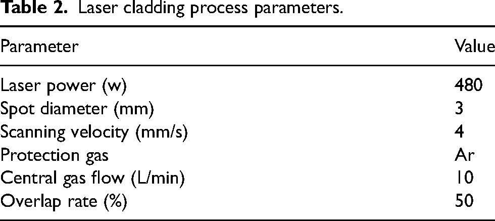
The prepared Q235 steel specimens were first treated with 180# sandpaper to removing the surface oxide layer, followed by sequential polishing with 400#, 600#, 800# and 1000# sandpaper, respectively. Then the samples were put into anhydrous ethanol and cleaned by ultrasonic cleaning instrument for 30 min to remove the oil and dirt on the surfaces. The laser cladding processes were performed using a pre-fabricated powder method. The molar ratio of Co, Cr, Fe, Ni, Mn, Cu powders was 2:1:1:1:1:x (x = 0, 0.25, 0.5, 0.75, 1, 1.25). The Co2CrFeNiMnCu x (x = 0, 0.25, 0.5, 0.75, 1.0, 1.25) HEACs was named Cu0, Cu0.25, Cu0.5, Cu0.75, Cu1.0 and Cu1.25 respectively, where the ratio was the mole ratio. The HEA powders were prepared according to the corresponding molar ratio. After that, it was put into the ball mill (Hunan Focucy Experimental Instrument Co.,LTD F-P400E) for 24 h to achieve a uniform mixture. Then the mixed HEA powders were uniformly coated on the surfaces of the Q235 steel specimen, with a powder thickness of approximately 0.5 mm. Optical fibre laser processor (Raycus RRWR) was used for laser cladding. The experimental parameters were shown in Table 2. Co2CrFeNiMnCu x HEACs with different Cu contents were prepared.
Laser cladding process parameters.
Microstructure characterisation
The prepared HEACs were processed into 10 mm × 10 mm × 5 mm samples using wire cutting technology. After being polished and smoothed with 600# sandpaper, the samples were ultrasonically cleaned in anhydrous ethanol for 30 min to remove surface impurities. The X-ray diffractometer (XRD, Ultima IV, Rigaku) was used for phases research and lattice constants calculation of the Co2CrFeNiMnCu x HEACs. The XRD instrument used a copper target, with a voltage of 40 kV, current of 40 mA, and a scanning range of 20° to 90° at a scanning speed of 4°/min. SEM (Regulus 8100, Hitachi) was used to study the microstructure and morphology of the HEACs. The energy-dispersive X-ray spectroscopy (EDS) was used to study the content and distribution of alloy elements in the coatings. A Vickers hardness tester (HUAYIN 310HVS-5) was used to test the microhardness of HEACs.
Corrosion resistance tests
Before electrochemical testing, the Co2CrFeNiMnCu x HEACs were soaked in 3.5 wt% NaCl solution for 30 min to stabilise the test systems. When the fluctuation of the steady-state open circuit potential (OCP) curve over time was less than 2 mV within 10 min, the systems were considered stable to carry out the next step of testing. The corrosion resistances of the Co2CrFeNiMnCu x HEACs were tested using an electrochemical workstation (potentiostat/galvanostat, AMETEK Parstat, Princeton Applied Research, 4000+). A three-electrode system was used, including a HEAC as the working electrode, platinum as the counter electrode and a saturated calomel electrode (SCE) as the reference electrode. After the steady-state OCP was relatively stable at 25 °C, the electrochemical impedance spectroscopies (EIS) of Co2CrFeNiMnCu x HEACs in 3.5 wt% NaCl solution were tested at frequencies ranging from 10−2 to 105 Hz with a signal amplitude of 20 mV, as well as the corresponding Tafel polarisation curves. The EIS data obtained were analysed using the Zsimpwin software. The Tafel data obtained were analysed using the Cview software.
Results and discussion
Microstructure of Co2CrFeNiMnCu x HEA powders
Figure 1(a–f) illustrates the irregular shapes of HEA powders after 24 h of ball milling. The particle sizes and shapes of the metal powders were completely irregular, exhibiting a chaotic and disordered distribution. The HEA powders did not form cohesive particles, and Co, having the highest content, was macroscopically distributed around other elements. Figure 1(a1–f1) displays the XRD spectra of the HEA powders after 24 h of ball milling. The spectra revealed that the HEA powders exhibited both FCC and μ phase. The Cu0 and Cu0.25 powder samples exhibited only one peak corresponding to the μ phase, whereas as the Cu content increased, the Cu0.5, Cu0.75, Cu1.0 and Cu1.25 powder samples showed two major peaks corresponding to the μ phase. The possible reason was that during the ball milling process, the prolonged and intense collisions between the powders and the milling balls leads to changes in the temperature and pressure of the environment in which the powders was located, and eventually there was the formation of μ-phase. Similar phase analysis has been carried out in previous literatures.40,41 By fitting the main peaks in the XRD spectra and utilising the Scherrer formula (1), Bragg's law (2) and lattice constant calculation formula (3),
37
the grain sizes and lattice constants of the HEA powders were calculated and summarised in Table 3.


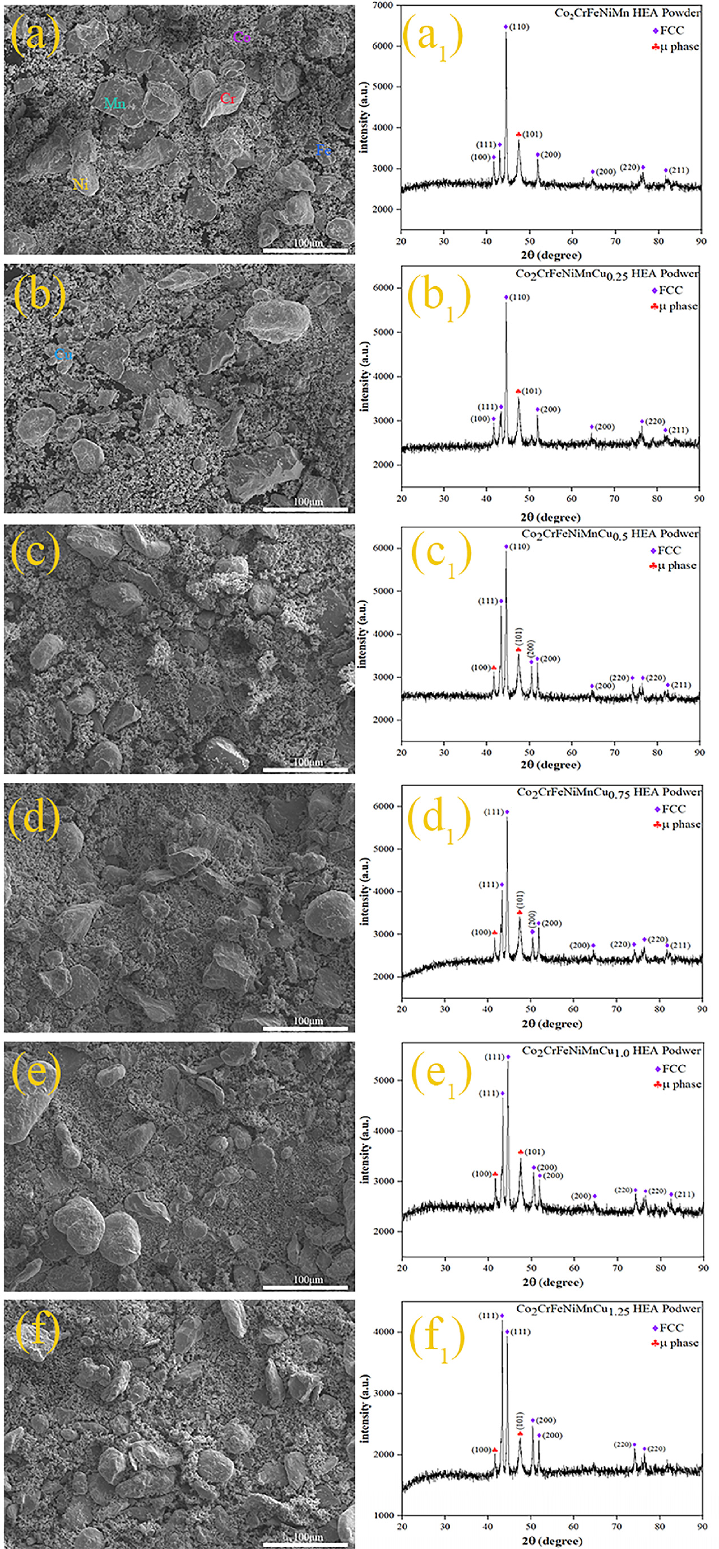
Co2CrFeNiMnCux (x = 0, 0.25, 0.5, 0.75, 1, 1.25) HEA powders aftter 24 h ball milling: (a)–(f) SEM morphologies, (a1)–(f1) XRD patterns.
Grain sizes, micro strains and lattice constants of Co2CrFeNiMn Cux HEA powders and HEACs.
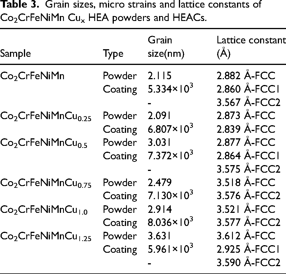
In these equations, D represents the grain size, K is the Scherrer constant, λ is the wavelength of the X-ray used, β is the full width at half maximum (FWHM), θ is the Bragg angle, d is the interplanar spacing, a is the lattice constant and h, k, l are the Miller indices of the crystal planes. XRD calculations revealed that the grain size of the alloy powders was in the nanometre range. Furthermore, the lattice constants of the alloy powders containing Cu increased with the Cu content. It is noteworthy that the atomic radii of Co, Cr, Fe, Ni, Mn and Cu elements are 1.25Å, 1.21Å, 1.24Å, 1.24Å, 1.27Å and 1.57 Å, respectively, with Cu having the largest atomic radius. 38 During the ball milling process, constant collisions and contacts among the elements promoted the formation of more atomic solid solutions. The differences in atomic radii, particularly the larger atomic radius of Cu, accelerated the process of mechanical alloying during the physical interactions. 42 . This phenomenon led to lattice distortion during ball milling, consequently altering the grain sizes.
Microstructure of HEACs
The Co2CrFeNiMnCu
x
alloy coatings were prepared on the surface of Q235 steel using the above-mentioned powders. The mixed entropy of each coating was calculated using Boltzmann's equation (4).
43
Figure 2 displays the XRD spectrum of the Co2CrFeNiMnCu x HEACs. The average grain size and lattice constants of the coatings were determined from the XRD spectrum and SEM images, as shown in Table 3. Coatings Cu0, Cu0.5 and Cu1.25 exhibited a dual-phase FCC structure, with varying diffraction peak intensities of the FCC1 and FCC2 phases based on different Cu contents. The lattice constants of both FCC1 and FCC2 phases increased with increasing Cu content, indicating an elevated lattice distortion of the solid solution with higher Cu content. On the other hand, coatings Cu0.25, Cu0.75 and Cu1.0 exhibited a single-phase FCC structure, but Cu0.25 had a distinct phase compared to Cu0.75 and Cu1.0. Specifically, Cu0.75 and Cu1.0 belonged to the FCC2 phase, while Cu0.25 exhibited the FCC phase. Comparatively, the number of diffraction peaks in the HEACs decreased, and the μ phase disappeared as compared to the powder XRD spectrum. Yeh et al. 1 previously highlighted that the formation of the FCC structure in HEAs was primarily attributed to the thermodynamic high-entropy effect, favouring the formation of a simple solid solution structure rather than complex intermetallic compound phases. On the one hand, there were interactions among the elements within the alloys, and the addition of Cu altered the lattice parameters of the alloys (see Table 3). Furthermore, variations in Cu content could affect the alloy's solubility and phase equilibrium. On the other hand, the formation of phases within the alloys was also subject to differences due to temperature gradients and cooling rates.
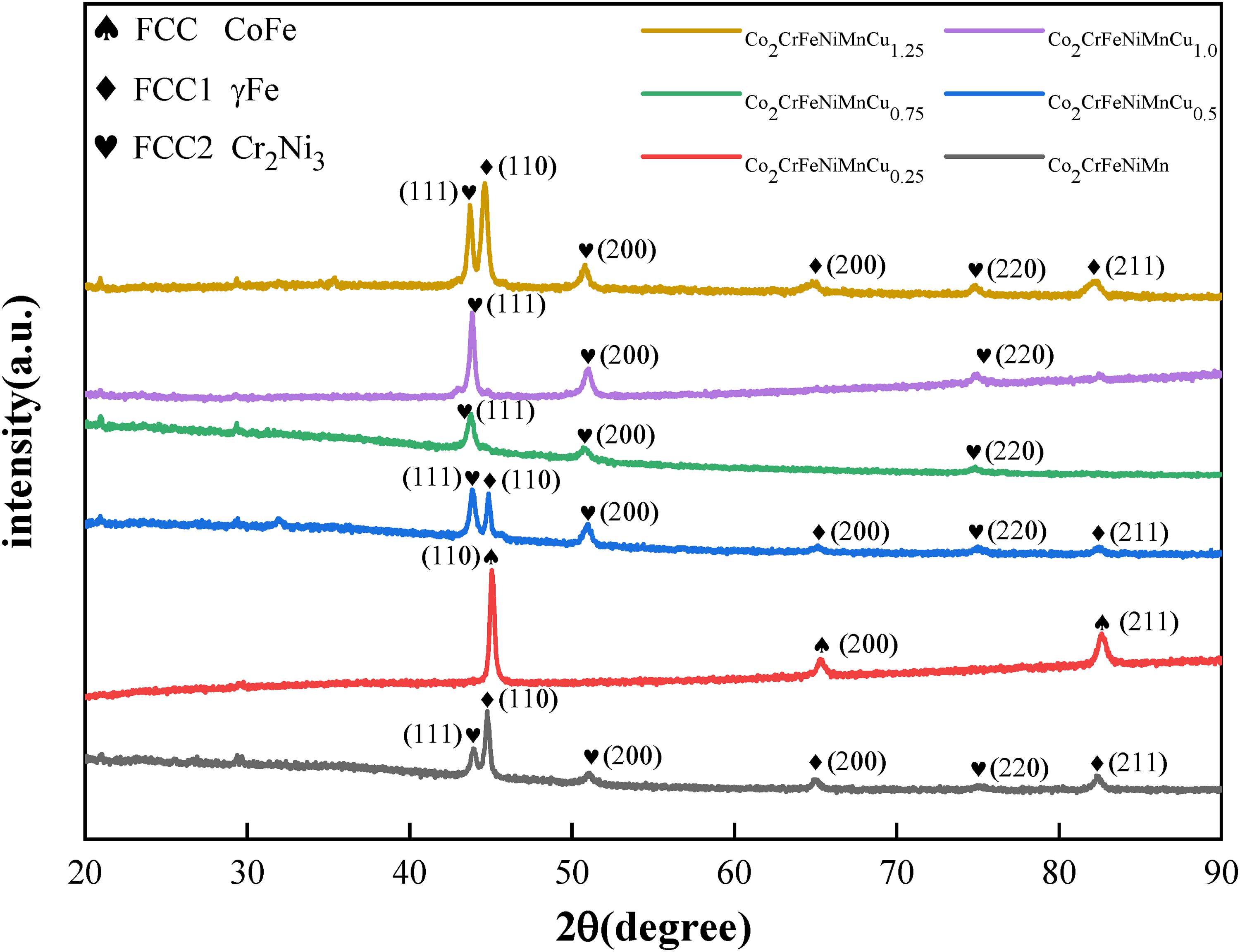
XRD of Co2CrFeNiMnCu x HEACs.
The microstructures of the Co2CrFeNiMnCu x HEACs were presented in Figure 3(a)–(f).The thickness of the coatings was approximately 0.5 mm. The microstructures were found to be uniform and dense, with a few pores present. Good metallurgical bonding between the coatings and the substrates was observed. To characterise the microstructures of the coatings, the top region (Figure 3(a1)–(f1)), the middle region (Figure 3(a2)–(f2)) and the bottom region bonded to the substrates (Figure 3(a3)–(f3)) were selected. The microstructure analysis revealed that the bottom region bonded to the substrate (red box in Figure 3(a3)) primarily consists of columnar dendrites. With the increasing of Cu contents, the columnar dendrites gradually lengthen. Wang et al. 44 reported that this behaviour was attributed to the temperature gradient from the top region to the bottom region during the laser cladding process and the inhibitory effect of Cu elements on dendrite growth at a certain undercooling. In other words, it was the result of grain refinement. The middle and top regions of the coatings primarily exhibited equiaxed grains, with a small amount of cellular crystals. Additionally, the middle region contained a minor presence of columnar dendrites, whose growth directions were not entirely consistent. The main factor contributing to this distinction was the influence of temperature gradients and cooling rates. The solidification process of the coatings took place at the rear of a moving melt pool, forming a curved surface from the bottom of the pool (where the boundary with the substrate was eventually formed) to the surfaces. A significant amount of heat dissipated from the melt pool into the substrates, and the cooling rates at the coatings-substrates interface were relatively slow. Conversely, at locations further away from the coatings-substrates interface, the cooling rates gradually increased, but the overall process was also quite rapid. Consequently, the temperature and cooling rates of different regions of the coatings were different, leading to an inconsistent growth rate of the grains, which were gradually refined from top to bottom.45,46 From the grain sizes of the coatings listed in Table 3, it was evident that different Cu contents resulted in different grain sizes. Moreover, the columnar dendrites at the bottom of the coatings became finer and longer with increasing Cu contents, indicating clear grains refinement.

SEM images of Co2CrFeNiMnCu x HEACs: (a) Cu0, (b) Cu0.25, (c) Cu0.5, (d) Cu0.75, (e) Cu1.0, (f) Cu1.25;(a1–f1) the upper area, (a2–f2) the middle area and (a3–f3) the bottom area.
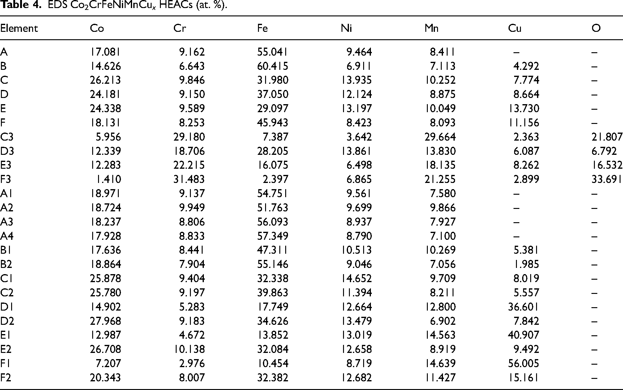
The EDS analysis results were presented in Table 4. EDS mappings were conducted on the middle region of the coatings, revealing a notably higher Fe element concentration than the theoretical value, which could be attributed to the diffusion of Fe elements from the substrates. While the actual proportions of the other elements deviated from the original theoretical proportions, they remained within a controllable range. This discrepancy was probably due to the influence of temperature gradients, leading to element segregation. The EDS analysis results for C3, D3, E3 and F3 in Figure 3(c1)–(f1) indicated that the white particles in Figure 3(c)–(f) were oxides of the component elements. The presence of pores in Figure 3(a) resulted from oxide reactions in the electrolytic corrosion solution, possibly due to suboptimal control of the protective gas flow rates during the laser cladding process. Further analysis of B1, C1, D1, E1 and F1 indicated that Cu tended to enrich between dendrites with increasing Cu contents, while Co, Cr and Fe were mainly distributed within the dendrites. This observation could be attributed to two main factors. Firstly, compared to the other five elements, Cu atoms had a larger atomic radius, higher solubility and diffusion coefficient. Secondly, there could be a repulsive effect between Cu and the other primary elements, leading to the preferential segregation of Cu at grain boundaries. Consequently, the degree of Cu segregation at grain boundaries increased with increasing Cu content.
EDS Co2CrFeNiMnCu x HEACs (at. %).
Microhardness of HEACs
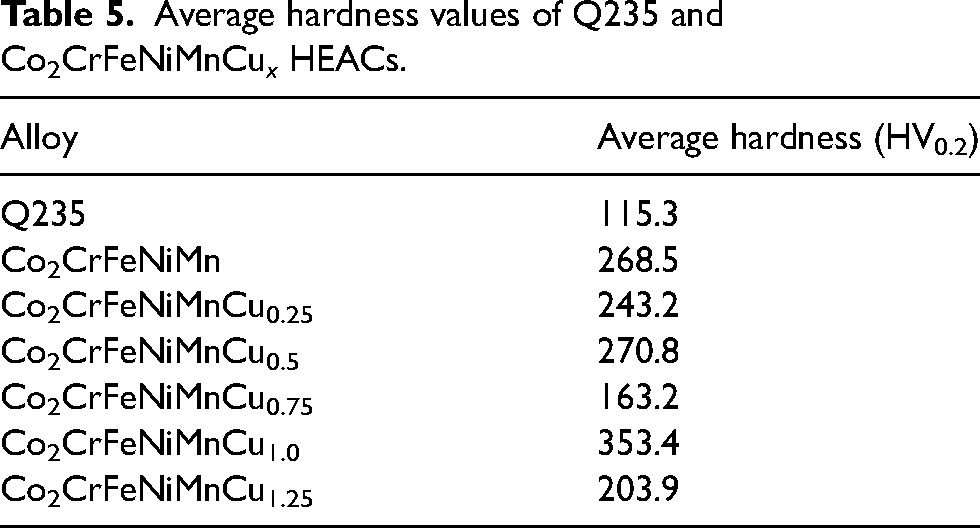
Microhardness can reflect the mechanical properties of HEACs, such as resistance to compressive deformation and wear, among other factors. The hardness distribution shown in Figure 4 demonstrated that the microhardness curves for various HEAs exhibited consistent trends. The hardness of the coatings gradually decreased from the top to the bottom,but the hardness values of the coatings were all greater than the substrates. The average hardness values (see Table 5) of the Cu0, Cu0.25, Cu 0.5, Cu0.75, Cu1.0 and Cu1.25 coatings and the substrates were measured as 268.5 HV0.2, 243.2 HV0.2, 270.8 HV0.2, 163.2 HV0.2, 353.4 HV0.2, 203.9 HV0.2 and 115.3 HV0.2, respectively. It could be observed that there was little difference in the hardness values for Cu 0, Cu 0.25 and Cu 0.5 coatings as the Cu content varies. However, the Cu 0.75 coatings exhibited the lowest hardness value, the Cu 1.0 coatings had the highest hardness value, and the Cu 1.25 coatings had a higher hardness value than the Cu 0.75 coatings but lower than Cu 0, Cu 0.25 and Cu 0.5 coatings. This suggested that there was no distinctive hardness gradient relationship among HEA coatings with varying Cu contents. The reason for the hardness gradient from the top of the coatings to the substrates was that, on the one hand, the diffusion of Fe elements within the substrates led to the hardness variations at different locations within coatings. On the other hand, during the laser cladding process, different regions of the coatings experienced varying temperatures and cooling rates, and atomic segregation occurred during rapid cooling. 47
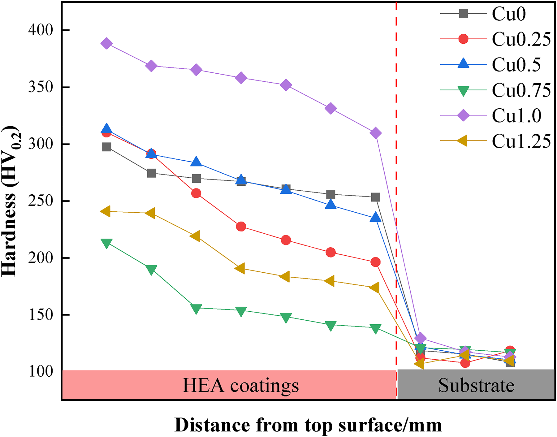
Hardness distribution of Co2CrFeNiMnCu x HEACs from top to substrate.
Average hardness values of Q235 and Co2CrFeNiMnCu x HEACs.
Electrochemical corrosion property of HEACs
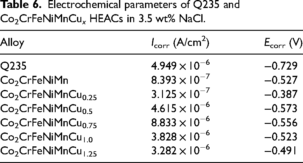
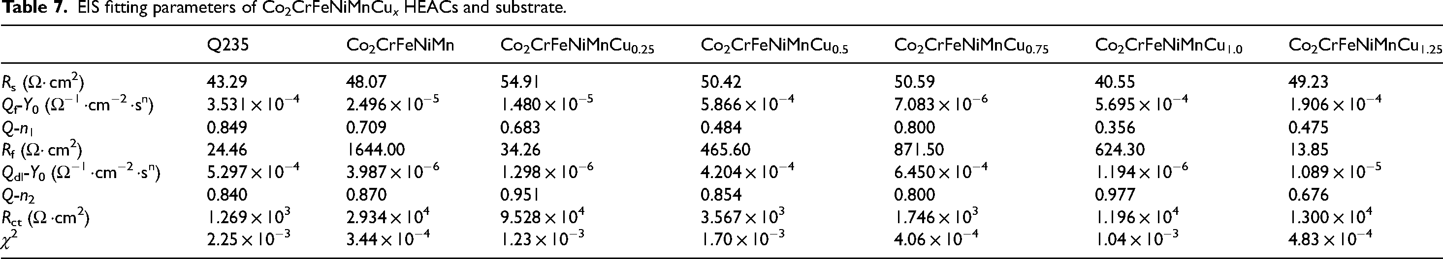
Figure 5 presents the dynamic potential polarisation curves of the Co2CrFeNiMnCu x HEACs in 3.5 wt% NaCl solution. The figure demonstrated that both the Q235 steel substrates and the Co2CrFeNiMnCu x HEACs exhibited a direct transition from the Tafel region to a stable passive region, without a passivation transition region. The corrosion current density increased relatively slowly in the passive region. When reaching the critical pitting potential, the passivation films were disrupted, and the current densities briefly and rapidly increased, transitioning from the passivation region to the transpassivation region. 48 Both the substrates and the HEACs exhibited a brief and rapid increase in current densities in the transpassivation region. The results indicated that the Co2CrFeNiMnCu x HEACs could spontaneously form protective passivation films in 3.5 wt% NaCl solution. Each HEACs of Co2CrFeNiMnCu x exhibited a relatively long passivation region. Compared to the passivation region of Cu0, the addition of Cu elements reduced the passivation region relatively. This result suggested that the addition of Cu inhibited the formation of the passivation films, consistent with the findings of Meng et al. 49 Table 6 lists a series of kinetic parameters obtained from Figure 5, including the corrosion potential (Ecorr) and the corrosion current density (Icorr). The corrosion rates of metal materials were positively correlated with Icorr and negatively correlated with Ecorr, indicating that a higher Ecorr and a lower Icorr resulted in better corrosion resistance of the material. 50 The results indicated that Cu0.25 exhibited the highest corrosion potential (−0.387 V) and the lowest corrosion current density (3.125 × 10⁻⁷ A/cm2), indicating the best corrosion resistance. The addition of a small amount of Cu could improve the corrosion resistance of the coatings (Cu0.25 > Cu0). However, excessively high Cu content reduced the corrosion resistance of the coatings (Cu0.5, Cu0.75, Cu1.0, Cu1.25 were all lower than Cu0). This was attributed to the excessive Cu content, which led to severe segregation at grain boundaries, resulting in localised galvanic corrosion. 49 EIS tests were conducted on the coatings to analyse the relative stability of the passivation films. The fitting of parameters were performed using an equivalent circuit model (Figure 6), generating Nyquist plots (Figure 7), Bode plots (Figure 8) and phase angle plots (Figure 9). The Nyquist plots of the HEACs shown in Figure 7 exhibited incomplete capacitive arcs for both the substrates and all HEACs, which were typically understood as charge transfer systems on non-uniform surfaces. 51 The curvature of the capacitive arcs usually reflected the corrosion resistance of the material, where a larger capacitive arc diameter indicated a higher charge transfer resistance and a lower corrosion current density, represented better corrosion resistance, which was related to the formation mechanisms of the oxide films on the coating surfaces. 52 Cu0.25 exhibited the largest capacitive arc, followed by Cu0, whereas Q235 substrate had the smallest capacitive arcs. The capacitive arcs of the other Cu content coatings were smaller than that of Cu0, but there were no apparent pattern of gradients change. A typical R(Q(R(QR))) circuit model was selected to fit the EIS data and analyse the passivation behaviour, and χ2 was used to evaluate the reliability of the fitting results. 53 When χ2 was between 10−3 and 10−4, it indicated that the selected equivalent circuit was reasonable, and the fitting results were meaningful. 54 The fitting parameters were shown in Table 7. Among them, Rs represented the solution resistance, Rf represented the passivation film resistance on the coating surface, Qf represented the capacitance between the passivation film and the solution. Rct represented the charge transfer resistance between the sample and the solution after the passivation film was disrupted and Qdl was the capacitance at that time. n1 and n2 (0–1) were dispersion coefficients. A higher n value indicated a higher density of the passivation film. The magnitude of Rct was positively correlated with the corrosion resistance of the coating, where a higher Rct indicated more difficult charge transfer and better corrosion resistance. The charge transfer resistances (see row Rct in Table 7) of the Q235 substrate and Cu0, Cu0.25, Cu0.5, Cu0.75, Cu1.0, Cu1.25 coatings were 1.281 × 10³Ω·cm2, 2.934 × 10⁴Ω·cm2, 9.528 × 10⁴Ω·cm2, 3.567 × 10³Ω·cm2, 1.746 × 10³Ω·cm2, 1.196 × 10⁴Ω·cm2 and 1.300 × 10⁴ Ω·cm2, respectively. The results indicated that the corrosion resistance of the coatings and the substrate was consistent with analysis of the dynamic potential polarisation curves.
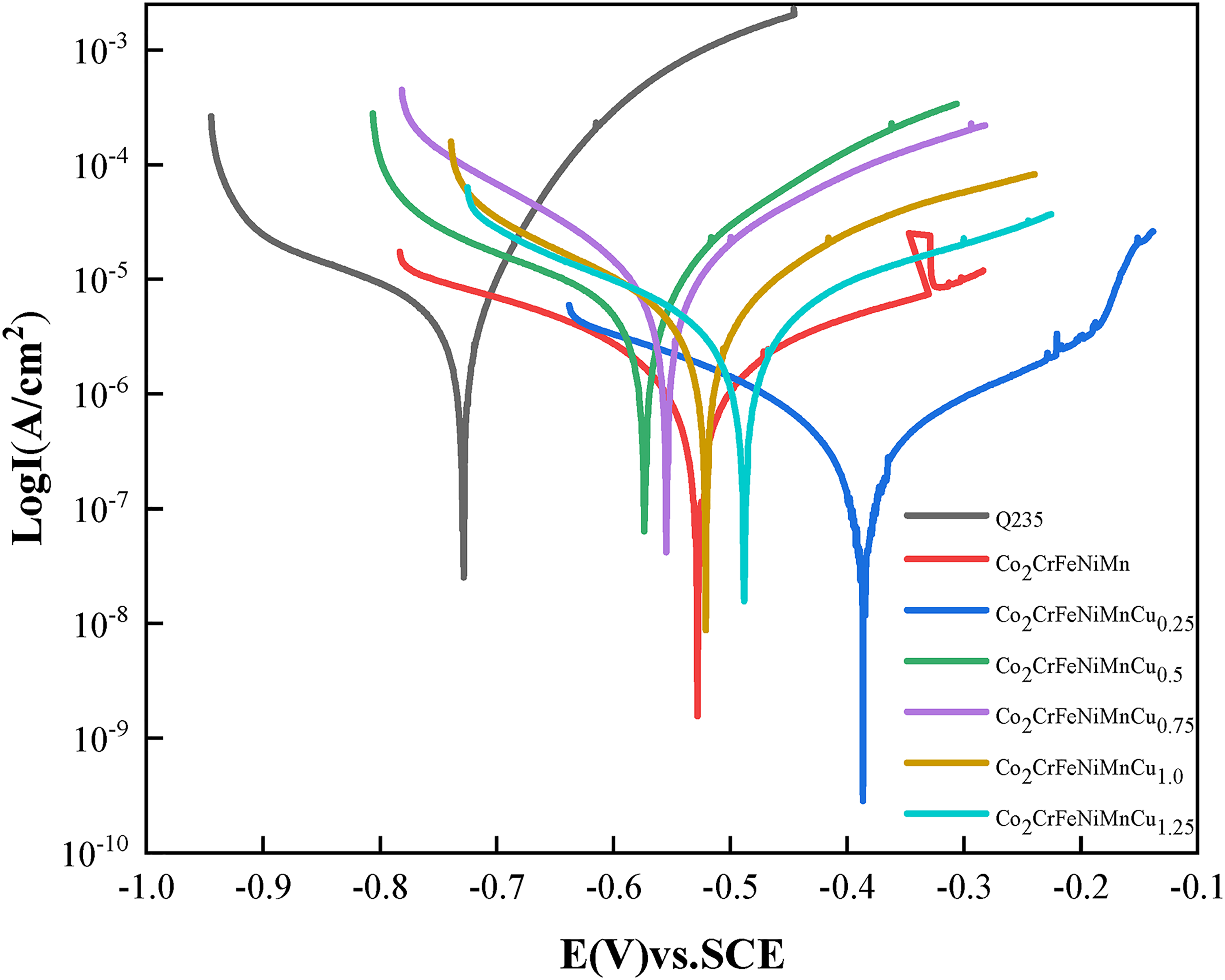
Potentiodynamic polarisation curves of the HEACs and Q235 steel in 3.5 wt% NaCl.
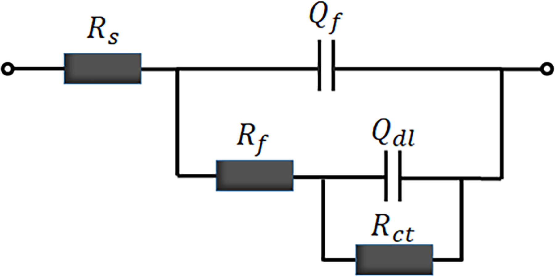
Schematic diagram of fitting circuit.
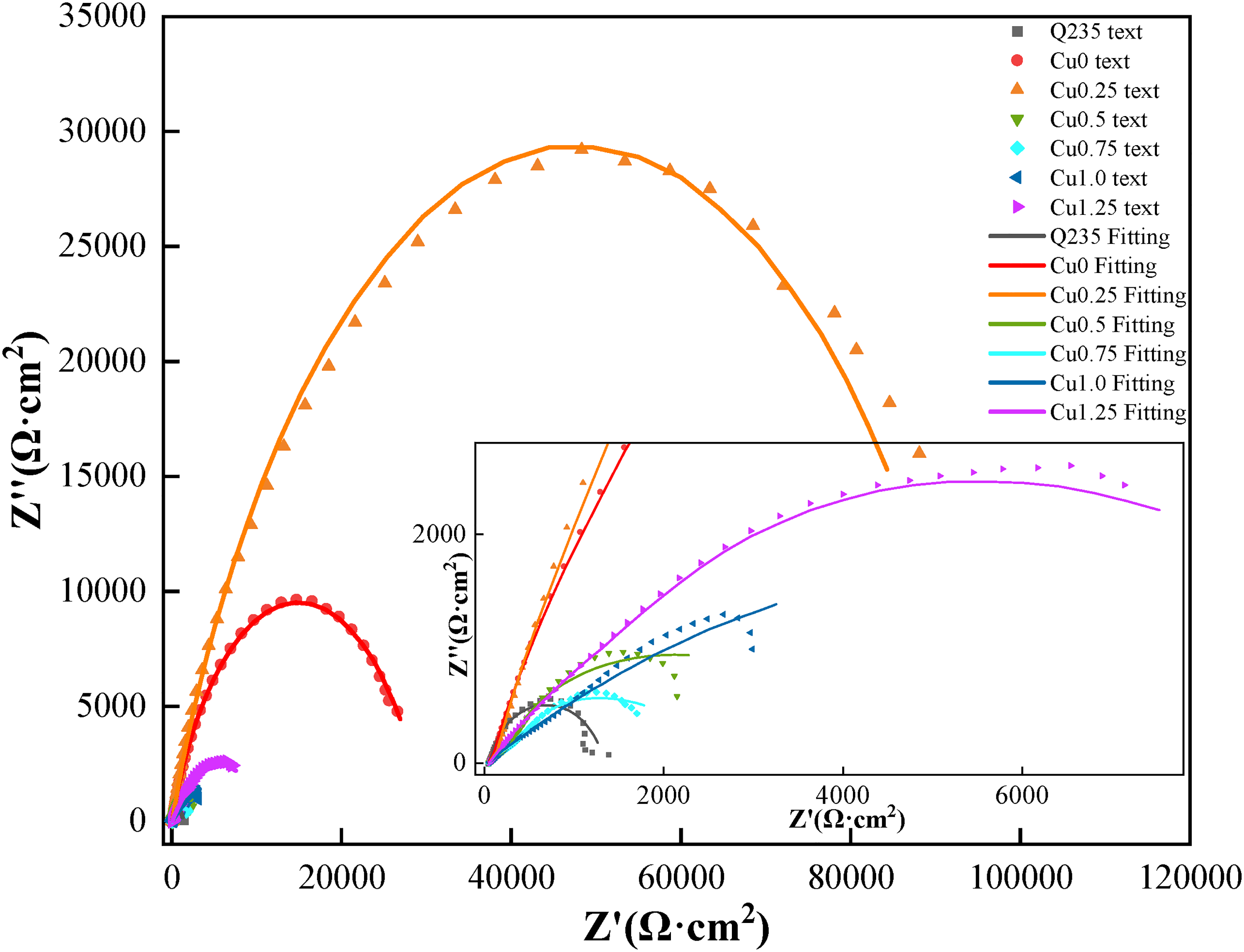
Electrochemical impedance spectrum of the HEACs and Q235 steel (Nyquist diagram).
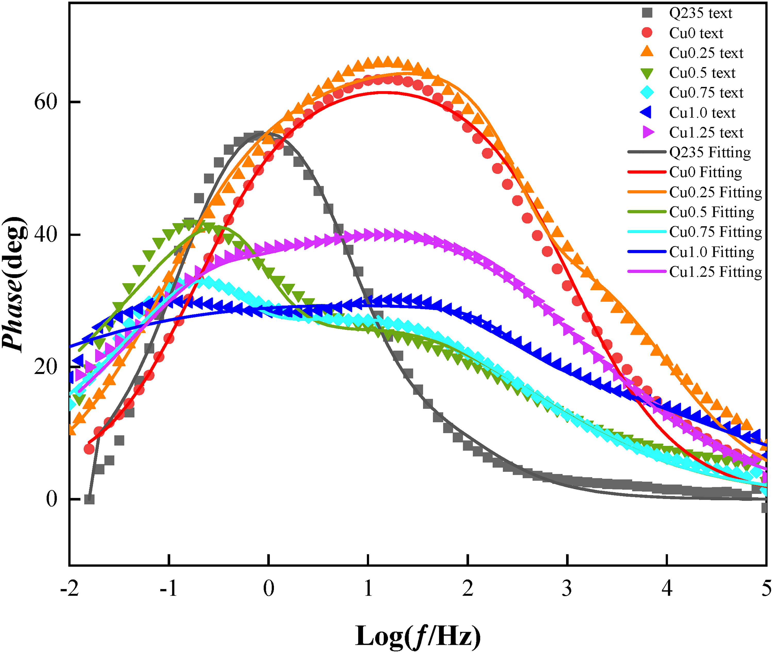
Electrochemical impedance spectrum of the HEACs and Q235 steel (Bode phase diagram).
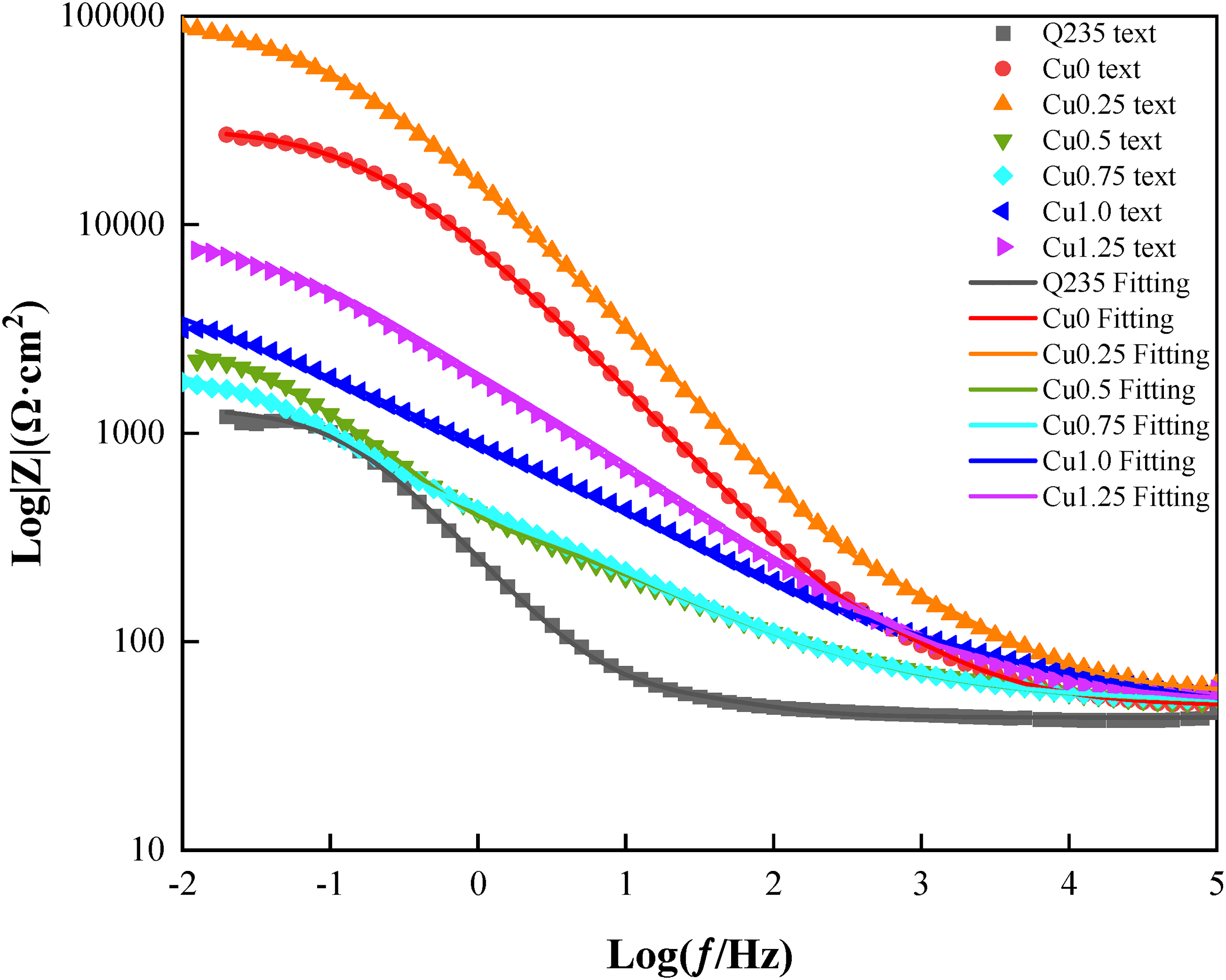
Electrochemical impedance spectrum of the HEACs and Q235 steel (Bode modulus diagram).
Electrochemical parameters of Q235 and Co2CrFeNiMnCu x HEACs in 3.5 wt% NaCl.
EIS fitting parameters of Co2CrFeNiMnCu x HEACs and substrate.
Figures 8 and 9 show the Bode impedance plots and Bode phase angle plots of the Co2CrFeNiMnCu x HEACs. In 3.5 wt% NaCl solution, the impedance (|Z|) of the substrate and the HEACs in the high-frequency range (104 to 105 Hz) was around 50 Ω·cm2. The impedance spectrum in the low-frequency range (10−2 to 10−1 Hz) represented the transfer resistance of the samples, reflecting the overall corrosion resistance and barrier ability to the corrosive medium of the coating. Coating Cu0.25 had higher transfer resistance at frequencies. The transfer resistances of the HEACs at low frequencies were higher than those of the substrates, indicating that the corrosion rate of the HEACs were relatively lower and provided better protection to the substrates in the same corrosive environment.
Mechanism of anti-corrosive property of HEACs
From the polarisation curves and EIS in Section ‘Electrochemical corrosion property of HEACs’, it can be deduced that the primary mechanism for protecting the steel substrate through coatings is passive films protection. Within the coatings, the elements Co, Cr and Ni readily combine with oxygen to form stable passive films, especially the addition of Cr contributes to pitting resistance at grain boundaries. 53 The passive films can effectively isolate the substrate from direct contact with corrosive media in the environment, Thereby playing a better role in protecting the surfaces of the substrates. The Fe element in the substrate tends to form Fe2O3, which possesses a strong adsorption affinity for anions but is susceptible to destruction by Cl−1. 37 Consequently, the substrate left unprotected by the coating exhibited the worst corrosion property. Furthermore, the coatings exhibit cathodic protection effects. Cu and Ni within the coatings have a higher potential than Fe, making it easier to get electrons and carry out a reduction reaction, thus slowing down the oxidation of the carbon steel (anode). Additionally, the coatings form a physical isolation layer between the carbon steel and the solution, obstructing the transfer of electrons or ions. This phenomenon effectively curtails the occurrence of anodic reactions, thereby retarding the oxidation process of carbon steel.
Conclusions
In this study, Co2CrFeNiMnCu
x
(x = 0, 0.25, 0.5, 0.75, 1.0, 1.25) HEACs were prepared on the surfaces of Q235 steel using laser cladding. A comparison of the compositions of the alloy powders and alloy coatings before and after laser cladding was carried out. Furthermore, the influence of Cu content variation on the microstructure, microhardness and corrosion resistance of the HEACs was analysed. The main conclusions were summarised as follows:
Following 24 h of ball milling, irregular HEA powders failed to form cohesive particles and exhibited a mixture of FCC and μ phase structures. However, after laser cladding, the resulting coating microstructure exclusively comprised the FCC phase, with the absence of the μ phase. The Co2CrFeNiMnCu
x
HEACs exhibited columnar dendrites, equiaxed crystals, and cellular crystals, with non-uniform grain growth direction. As the Cu content increasing, the grains became finer and elongated. Cu tended to accumulate between the dendrites, while Co, Cr, and Fe were concentrated within the dendrites. During the laser cladding process, there was hardness gradients in the coatings organisation along the cross-sectional direction, which was influenced by the temperature gradients, cooling rates and the presence of Fe dilution in the substrates. The primary mechanism for protecting the steel substrates through coatings was passive films protection. The inclusion of modest amounts of Cu could improve the corrosion resistance of coatings, yet an excessive Cu content had the adverse effect of diminishing their corrosion resistance.
Footnotes
Acknowledgements
The authors would like to thank the project team assistance with funding. Thank you for the thoughtful and thorough guidance of your mentors.
Author contributions
Declaration of conflicting interests
The authors declare that they have no known competing financial interest or personal relationships that could have appeared to influence the work reported in this paper.
Funding
The author(s) disclosed receipt of the following financial support for the research, authorship, and/or publication of this article: This research work was financially supported by The Key Research Program of Frontier Sciences, CAS (ZDBS-LY-DQC025).