
Abstract
The precipitation of intermetallic compounds (IMCs) in an aluminium alloy Al-7Si-0.4Mg (A356) was studied, making additions of Fe, Sr, and Mg. The experiment avoided metallographic techniques, using a novel experimental approach in which the outside surface of the cast metal was studied. Precipitation of IMCs was observed to occur on the surface of oxide bifilms in suspension in the liquid metal, occasionally as a Sr-rich IMC growth from one side and a Fe-rich IMC growth from the other, corroborating the structure of the bifilm as having two wetted outer sides. The bifilms onto which heavy IMCs had precipitated were observed by nanotomography to sediment rapidly, indicating a potential method of cleaning secondary metals from both bifilms and metals like Fe.
Introduction
The high affinity of liquid aluminium for oxygen results in surface oxide films on the liquid alloy during melting and casting. The oxide layer formed on the surface can fold over upon itself during pouring a casting, as a result of the naturally occurring surface turbulence, trapping the dry side of the surface film to the dry side of the opposing fold to create an unbonded interface which can survive in the liquid metal. This doubling over of surface films during the pouring of the liquid alloy leads to the formation of defects called ‘bifilms’, having a structure (i) whose internal dry, unbonded interface serves as an initiation site for structural cracks and (ii) whose external wetted interfaces with the matrix serve as precipitation sites for intermetallic compounds (IMCs).1,2
Cao and Campbell
3
discovered that in Al-11Si-0.4Mg alloy, the
The authors also reported that during the very early stages of growth of the IMC on the compact and convoluted bifilms in suspension in the liquid alloy, the thin
This flattening and straightening of the bifilm appeared to be the mechanism by which the bifilm changed from a convoluted, compact, moderately harmless inclusion to becoming an effective ‘engineering crack’, greatly damaging the properties of the alloy, and explaining the effectiveness of Fe as impairing the ductility of Al-Si alloys. In addition, the cleanness of the liquid Al-11.5Si-0.4Mg-1.2Fe-1.1Mn alloy was improved by the formation of IMCs containing 50% Fe and 70% Mn onto bifilms as preferred substrates, and the subsequent sedimentation of the bifilms weighed down by the dense precipitated IMCs.
5
One of the authors
4
suggests that
Miresmaeili et al.
6
added 0.1Sr to an Al-Si-Mg alloy and observed the formation of star-like Sr-rich intermetallics on the surface of castings poured into small stainless steel crucibles. The star-like
Effectively, this simple and, so far as the authors are aware, unique procedure, permitted the observation of IMCs on the wetted surfaces of (one half of) a bifilm. It was the technique adopted in this work to study the formation of IMCs on bifilms in aluminium alloys.
Que and Mendis
7
also investigated how Fe-containing intermetallics nucleate during the solidification process and the phase competition between the compounds in Al-Fe-Si alloys using SEM, EBSD, and TEM, confirming the nucleation of
Kumar et al.
8
studied the compounds involved in grain refinement of Al alloys by Ti and B compounds, finding that
Experimental procedure
Miresmaeili's technique 6 of casting the aluminium alloy into small stainless steel crucibles was employed. The IMCs visible on the surface formed on the underside of the surface oxide film of the casting and were clearly visible through the film as a result of its extreme thinness. Incidentally, although Figure 1 indicates that the curved side of the casting was used (which in principle was as appropriate as any other surface of the casting) it was found most convenient in this work to use the flat base of the casting.
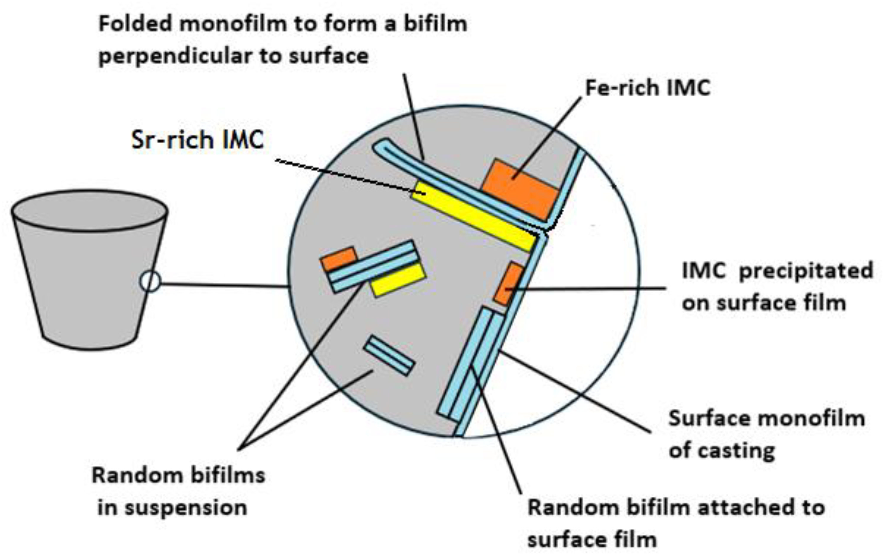
Relation between the surface monofilm, bifilms in suspension in the melt, and intermetallic compounds forming on bifilms and the surface monofilm.
To investigate the precipitation of IMCs on the wetted sides of oxide films, three different alloys were produced based on A356 alloy (as in Table 1) with additions of Al-20Fe, Al-10Sr, and Al-5Mg master alloys to promote the formation of multiple IMCs. The relative compositions of the alloy additions are shown in Table 2. The alloys were melted in a 1 kg capacity clay-graphite crucible using 20 kW induction power at 5000 Hz frequency.
A356 Aluminium Alloy Nominal Composition.
Alloy additions to 356 aluminium alloys.
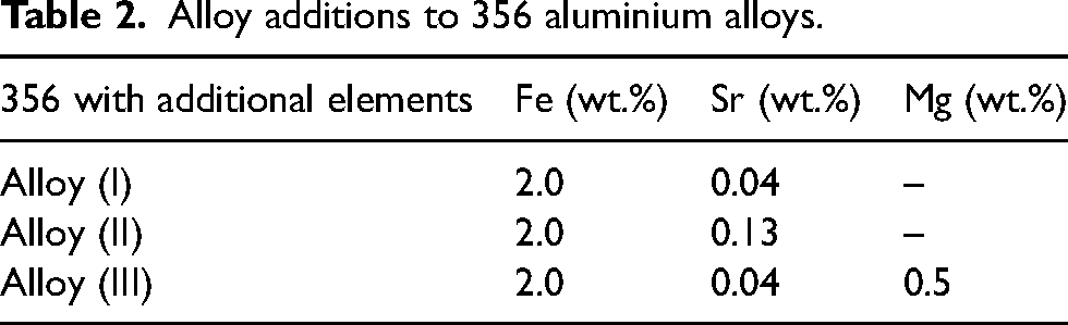
For the preparation of Alloys (I) and (II), when the melt temperature reached 800°C, 2Fe (numbers refer to weight percent addition) was added from the Al-20Fe master alloy. When the temperature was reduced to 730°C, 0.04Sr for Alloy (I) and 0.13Sr for Alloy (II) were added by the Al-10Sr master alloy. The alloys were held at 730°C for 20 min to ensure additions were fully dissolved and homogenised. For Alloy (III), when the melting temperature reached 700°C, 0.5 Mg was added by the Al-5Mg master alloy. Subsequently, the temperature was increased to 800°C, and 2Fe was added by the Al-20Fe master alloy. The temperature was then reduced to 730°C, and 0.04Sr was added from the Al-10Sr master alloy. The alloy was held at 730°C for 20 min to ensure additions were fully dissolved and homogenised.
It is worth noting that the original A356 alloy ingots (and possibly the master alloys) would have been secondary alloys, and therefore had a history of having been melted and cast previously, and during this work, would have suffered some turbulence. All would therefore contain an unknown quantity of preexisting bifilms, as is typical for cast metals. The alloys were poured at 740 ± 10°C into stainless steel crucibles (SSCs) with an upper diameter of 42 mm, base diameter of 30 mm, height of 40 mm and wall thickness of 0.5 mm. The crucibles were preheated to 200°C prior to pouring.
The taper of the crucibles allowed the solidified castings to be removed from moulds without difficulty. No preparation of the castings was required. The IMCs were seen, appearing to be on the surface of the castings, and were subjected to microstructural analysis. Phase identification was performed using a Bruker D8 Advance XRD. A Zeiss EVO 15 SEM coupled with energy dispersive X-Ray (EDX) and backscattered electron (BSE) imaging was employed to examine the interfaces and phase compositions. 2D X-Ray tomographic images of castings were obtained using Bruker SkyScan 2211 X-Ray nanotomography.
To clarify the presentation of results and the discussion of the findings, Figure 1 illustrates the concepts central to this study.
Results from alloy (I)
SEM image of Alloy (I) shows the microstructure in Figure 2(a). Interestingly, the EDX map shows a Fe-rich IMC on one side of a linear feature (interpreted as a bifilm) in Figure 2(c), whereas in Figure 2(d), an IMC rich in Si has precipitated on its other side.
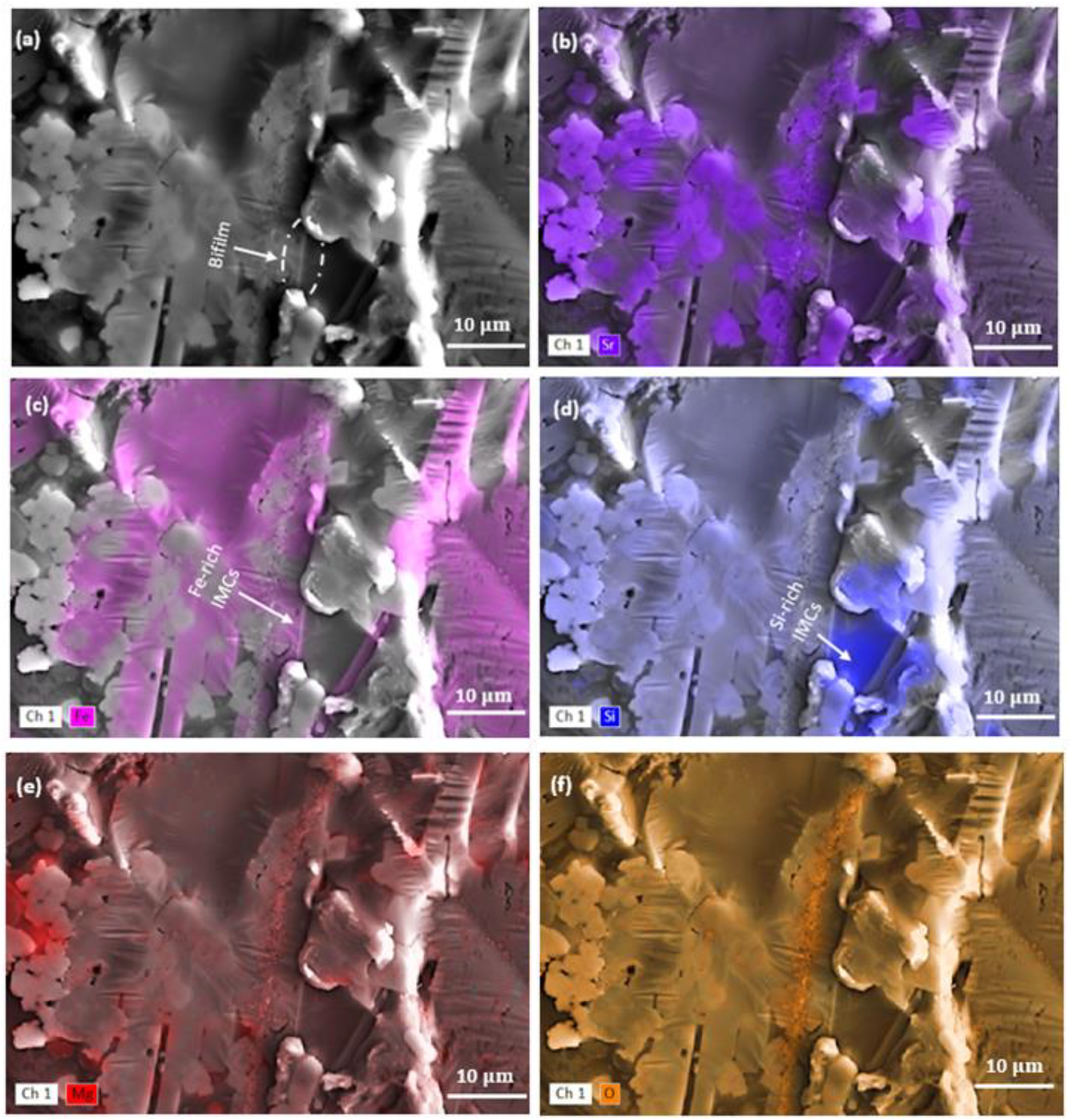
Alloy (I) showing (a) a general SEM image of microstructure and (b) is sr. (c) EDX map highlighting a Fe-rich IMC on one side of a bifilm and (d) Si map showing a Si-rich IMC on the opposite side of the same bifilm. Map (e) is Mg, and (f) is oxygen.
In the element distribution map (Figure 3), there are thin green (P2) and blue areas (P3) between the Fe-rich and Si-rich IMCs. These areas contain oxygen. The red and light blue areas also show oxygen at these locations. In addition to their long, thin morphology, the presence of oxygen strongly suggests these features are oxide bifilms.
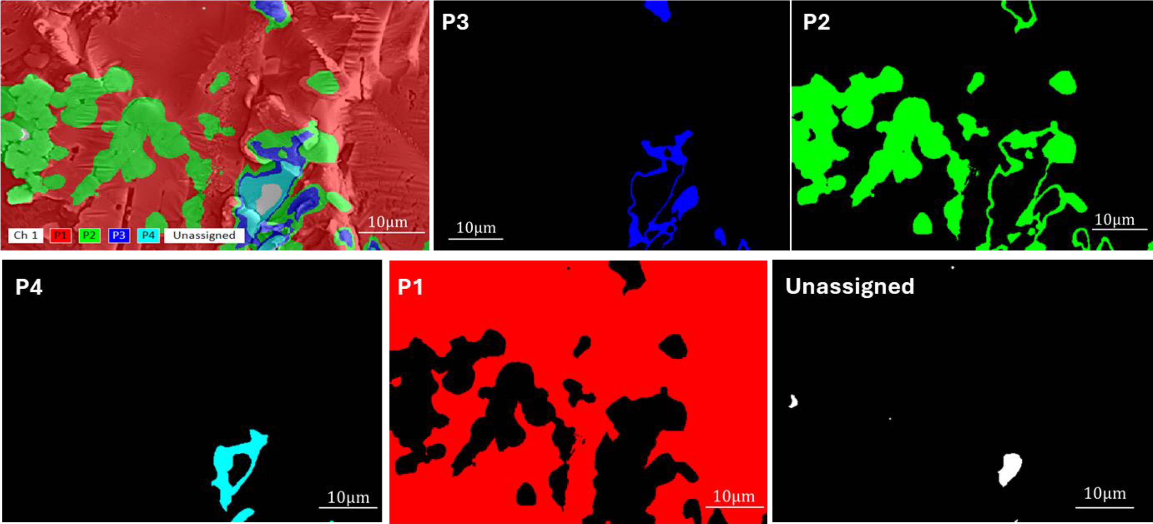
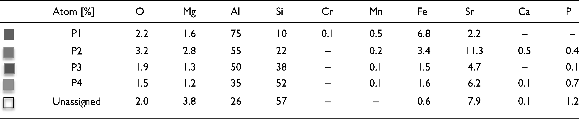
The elemental atomic [%] of map areas in Fig. 3.
Results for alloy (Ii)
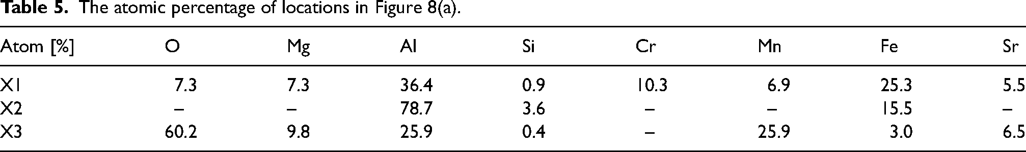
The particles and oxide film phases in Figure 4(a) and (b) were observed through BSE imaging, and the atomic percentage of elements was measured by EDX at locations X1, X2, X3, X4, X5, and X6 in Table 4. The XRD results (Figure 5) were evaluated comparatively. Additionally, the elemental distribution map of Figure 4(b) is shown in Figure 6.
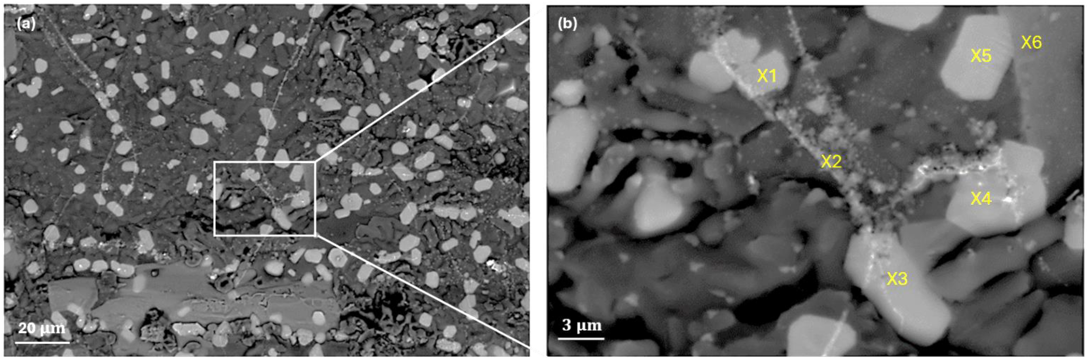
(a) BSE mode SEM image illustrating for alloy ii the distribution of

XRD results of alloy (ii). The peaks in the graph indicate different phases present in the material`s crystal structure. ), 
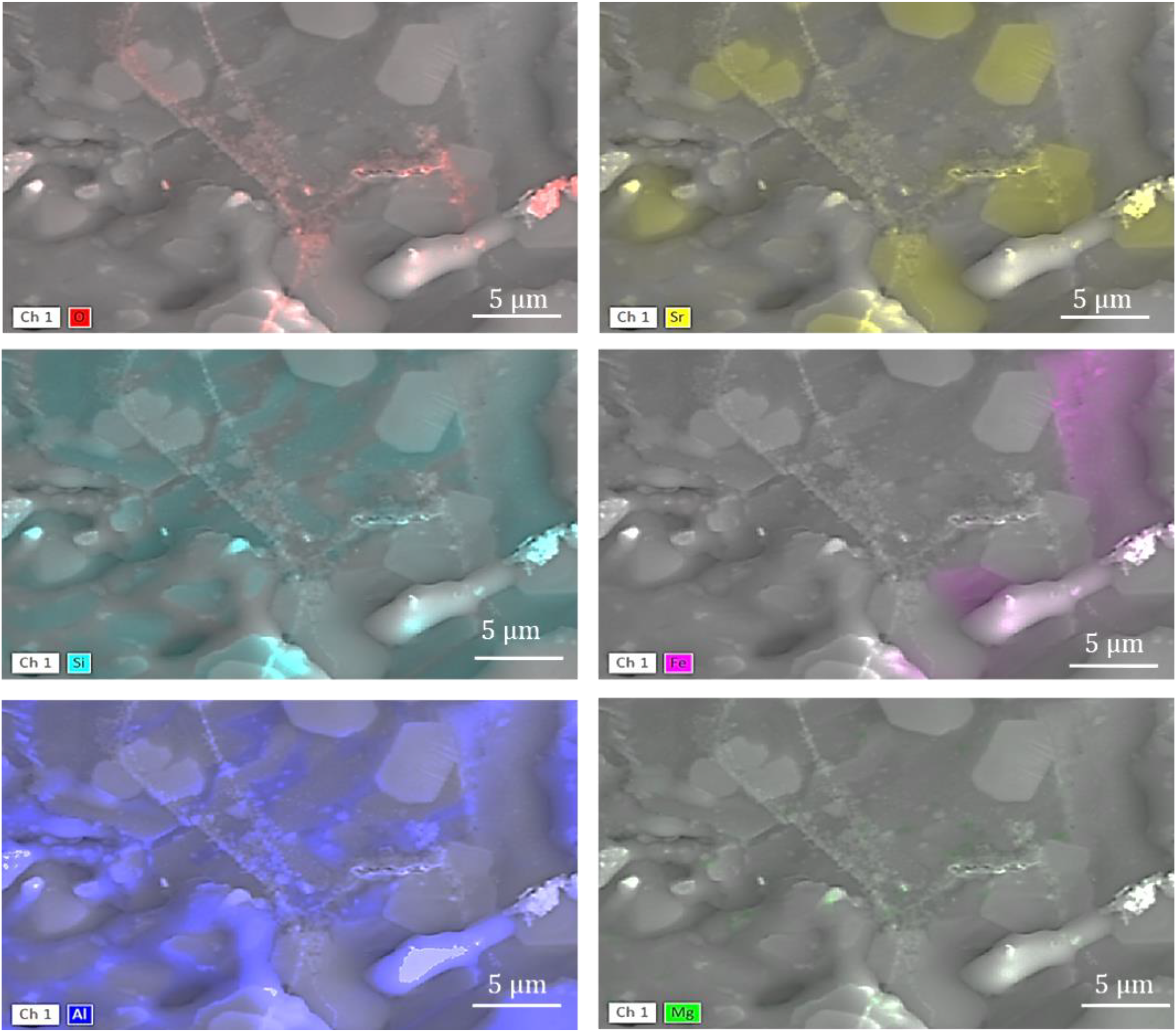
Alloy (ii). A map of elements in Figure 4(b).
Atomic percentage of elements in Figure. 4(b).
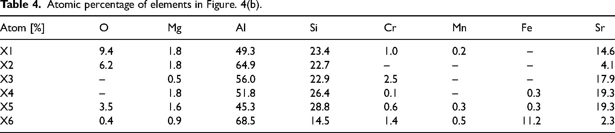
Therefore, both the EDX and XRD results indicate the possible presence of the
In Figure 6, the XRD analysis of Alloy (II) identified the features seen in Figures 4 and 5 as fine oxide particles forming a ragged bifilm, linking large crystals of
Figure 7 shows gentle folds in the surface of the IMC, schematically shown earlier in Figure 1. It seems, therefore, that the IMC precipitated on the underside of the surface oxide skin of the casting as it solidified, but because of a shape and/or volume change of the precipitating phase, the surface oxide film substrate has been deformed slightly, developing rucks in the otherwise smooth surface of the exterior oxide film on the casting. The precipitated IMC appears to be at an early stage of its growth, still sufficiently thin to follow the undulations of its substrate, as first observed by Cao and Campbell. 3
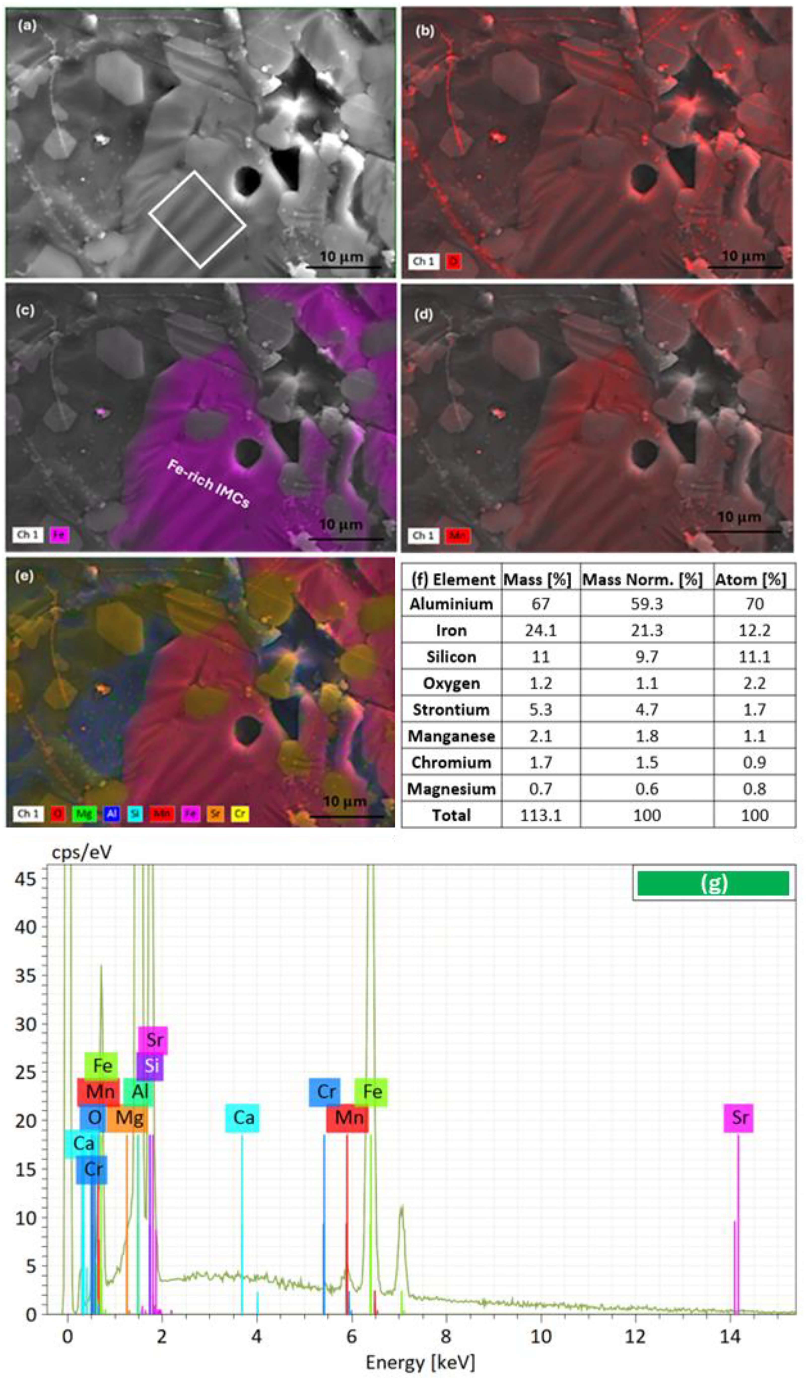
Alloy ii. (a) SEM image showing undulations, in the white box area. (b) EDX map for oxygen (O); (c) Fe; (d) Mn; and (e) highlighting the elemental distributions. Images (c) and (d) show a region of (Fe + Mn)-rich IMC. (f) and (g) represents EDX elemental composition and spectrum for the white line box area.
Results for alloy (III)
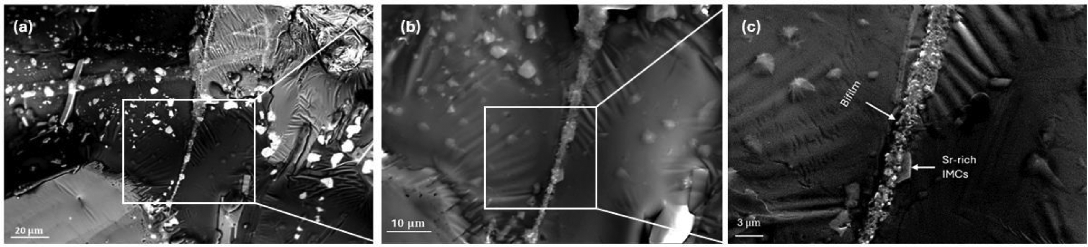
The microstructural examination of Alloy (III) indicated the presence of an oxide film as a faint background signal in Figure 8(b). The oxide film is probably a bifilm because it has a large area of its surface covered with a Fe-rich IMC seen in Figure 8(c). The SEM image in Figure 8(a) was labelled with X1, X2, and X3. The atomic percentage of these spots is presented in Table 5.
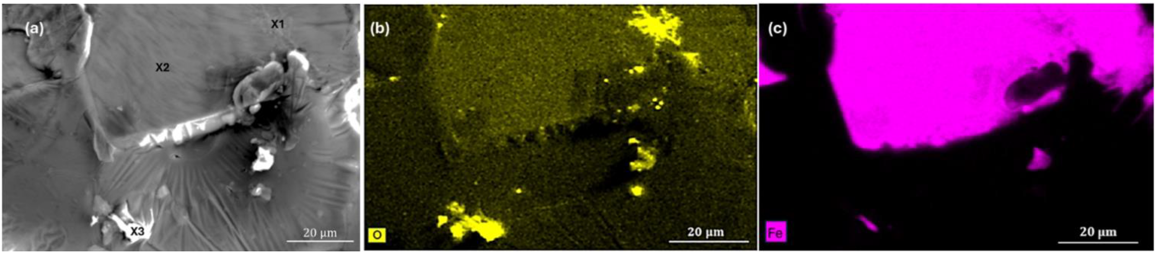
Alloy (III) showing (a) SEM image of surface. (b) EDX map showing elemental oxygen (O) and (c) Fe distribution.
The atomic percentage of locations in Figure 8(a).
The Fe-rich phase of Figure 8 covering the upper part of the bifilm (X2 region) appears to have strengthened and stiffened the bifilm, keeping it smooth, preventing it being deformed by the elongated precipitate formed on the film. In contrast, the lower part of the bifilm substrate (near X3 region) has deformed, forming rucks, as appears to be common behaviour in these alloys.
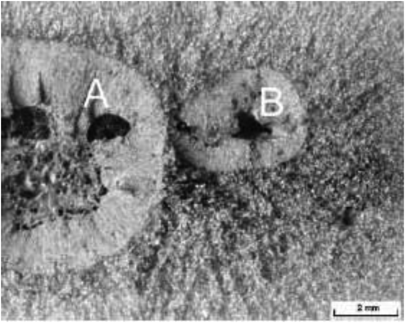
In Figure 9, the central linear feature is a bifilm. However, it appears to have two different varieties of precipitate formed on it: (i) a fine, granular precipitate and (ii) larger crystals (identified as Sr-rich IMCs).
Alloy III. SEM image of a complex oxide film, decorated with fine particles and larger particles of Sr, Si, and Mg-rich IMCs. (Phases identified by EDX in Figure 10).
The undulations are simply folds in the surface oxide skin of the casting, which would have been originally formed smoothly against the smooth surface of the stainless steel, but has subsequently been perturbed by the strains of the formation of the particle.
BSE imaging was employed to further investigate the microstructural characteristics, examining other regions of the exterior surface of Alloy (III). The BSE images provided insights into the distribution and interaction of the IMCs on the exterior surface of the casting (notice the large Fe, Mn, and Cr compound in the bottom left of Figure 10), but seem likely to be reflecting the general distribution within the interior alloy matrix Figure 11.
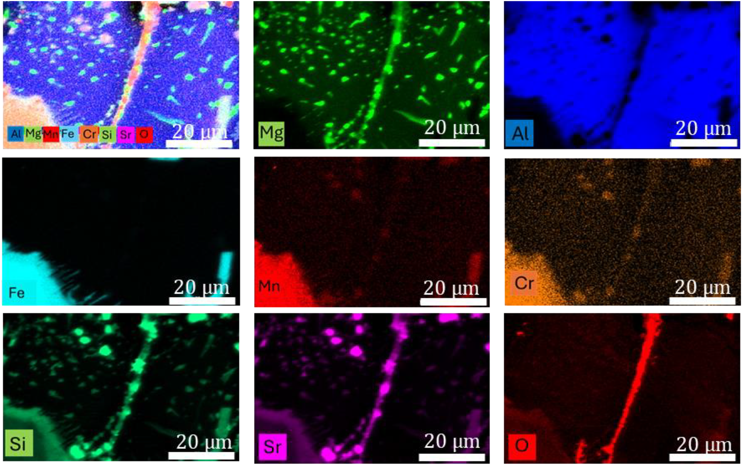
EDX map images of Figure 9b.

XRD results of alloy (III) the peaks in the graph indicate different phases present in the material`s crystal structure: ).
The sedimentation behaviour promoted by the precipitation of IMCs on bifilms is seen in the 2D tomographic images of the interior of casting Alloy II in Figure. 12. These images confirm that the large IMCs are associated with the large oxides (it seems probable that the smaller IMCs and smaller oxides are simply not sufficiently resolved to confirm an association), and further confirms that the larger IMC/oxide bifilm population has sedimented towards the bottom of the casting. The population of smaller particles would be expected to settle more slowly, explaining their more widespread distribution.
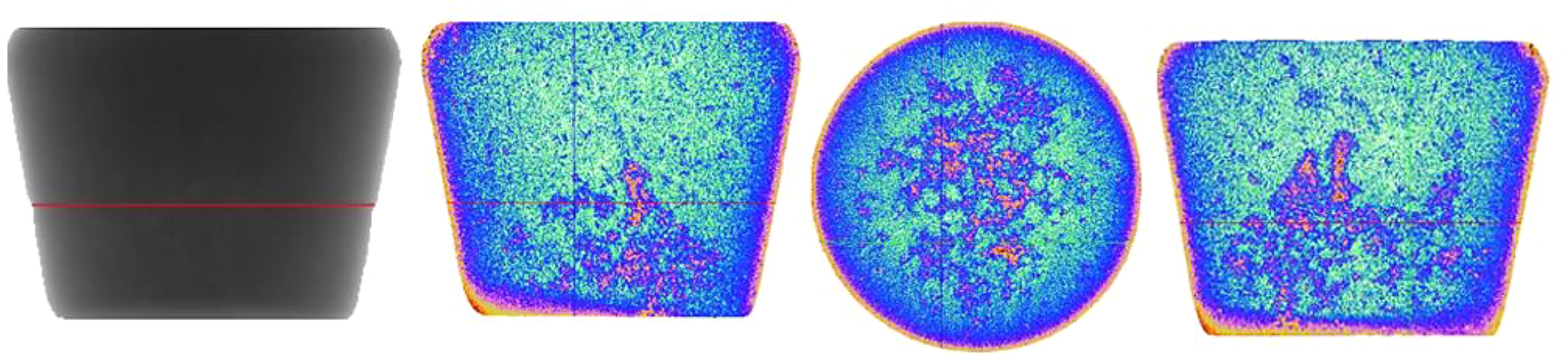
High-Resolution X-ray nanotomography shows 2D images of alloy (ii).
Discussion
Whereas cast alloys are normally sectioned and polished to study structure, in this work, the target of the study was the outer surface of the cast alloys. In this way, IMCs observed on the cast surface were assumed to have precipitated on the inside surface of the surface oxide film of the casting and so were observed through the extremely thin oxide skin of the casting. Effectively, the IMCs were on the wetted inside surface of the surface oxide film. The geometry simulated that of the precipitation of an IMC on the wetted exterior of a bifilm, and was effectively being viewed as though from the interior of the bifilm. The involvement of zero metallographic preparation was not only a convenient technique to study substances precipitated on bifilms, but the technique is powerful because the object of study has not been affected by the preparation technique.
At other locations on the casting surface, oxides which had been folded from the surface into the interior of the cast alloy, creating a bifilm at right angles to the cast surface, could also be observed as illustrated in Figure 1. In such cases, it gave the opportunity to look down the length of the ‘air gap’ between the halves of the bifilm, observing IMCs which may or may not be on one or both sides of the bifilm (Figure 1).
The bifilm exhibited in Figure 2 illustrated the growth of Si-rich and Fe-rich intermetallics in opposite directions from its two sides, providing evidence of the two-film symmetry of the bifilm and that different intermetallics clearly find them favoured substrates.
A second example is shown in Figure 4(b), suggesting that different IMCs on the two sides are not unusual observations but seem likely to occur often. Furthermore, the number of IMCs seen formed on oxide films strongly suggests that precipitation of compounds on bifilms may be the norm.
The nucleation of IMCs on bifilms
From his revolutionary experiments on the grain refinement of magnesium, studying the nucleation of magnesium on magnesium oxide, Fan 11 accepted that MgO was a poor nucleant for Mg. However, counter-intuitively, he achieved a prolific grain refining action. He explains this as the result of the huge density of MgO surfaces provided by his intense shearing technique. Nucleation on the few favourably lattice-matching nuclei which may have existed in the melt was irrelevant, being overwhelmed by the vastly superior numbers of MgO nuclei, yielding an effective grain refining action with a uniquely fine as-cast grain size.
The films suspended in the melt would be logically expected to be always bifilms as is corroborated by the observation of the nucleation and growth of IMCs from both sides. (The oxide monofilms on the surface of the casting, central to this work, are exclusively the surface oxide of the casting, constituting effectively ‘half bifilms’).
The distribution of
The undulating waveform seen in Figure 7 and other images is a natural feature of films, confirming them to be films, and confirming them to be thin. 4 Because the surface film on the casting is formed against the stainless-steel wall, it is assumed to be initially flat. Its non-flat forms must have been the result of mechanical compression or stretching or other deformation. It is assumed that the deformation is associated with the formation of the intermetallic particles, each of which will confer a characteristic volume and shape change.
Studies by Cao 4 observed that the early layers of Fe-rich precipitate follow the irregular wavy structure of randomly suspended bifilm. But as the particle thickens, its increasing rigidity gradually causes it to straighten, adopting its recognisable crystal morphology. The bifilm in contact with a crystal face is therefore forced to become atomically flat, as an extensive flat crack, thus reducing properties when it is recalled that this behaviour will be repeated throughout the microstructure, creating a structure resembling a ‘snowstorm’ of cracks.
At the same time, the outer regions of the bifilm, outside the contact area of the growing IMC, will necessarily be deformed to accommodate the stretching or compression suffered by the portion of the bifilm inside or alongside the growing crystal. Thus, the free-floating bifilms or surface monofilm outer regions surrounding IMCs are likely to develop accordion-like folds, as seen in Figures 8, 9(a), and 13.
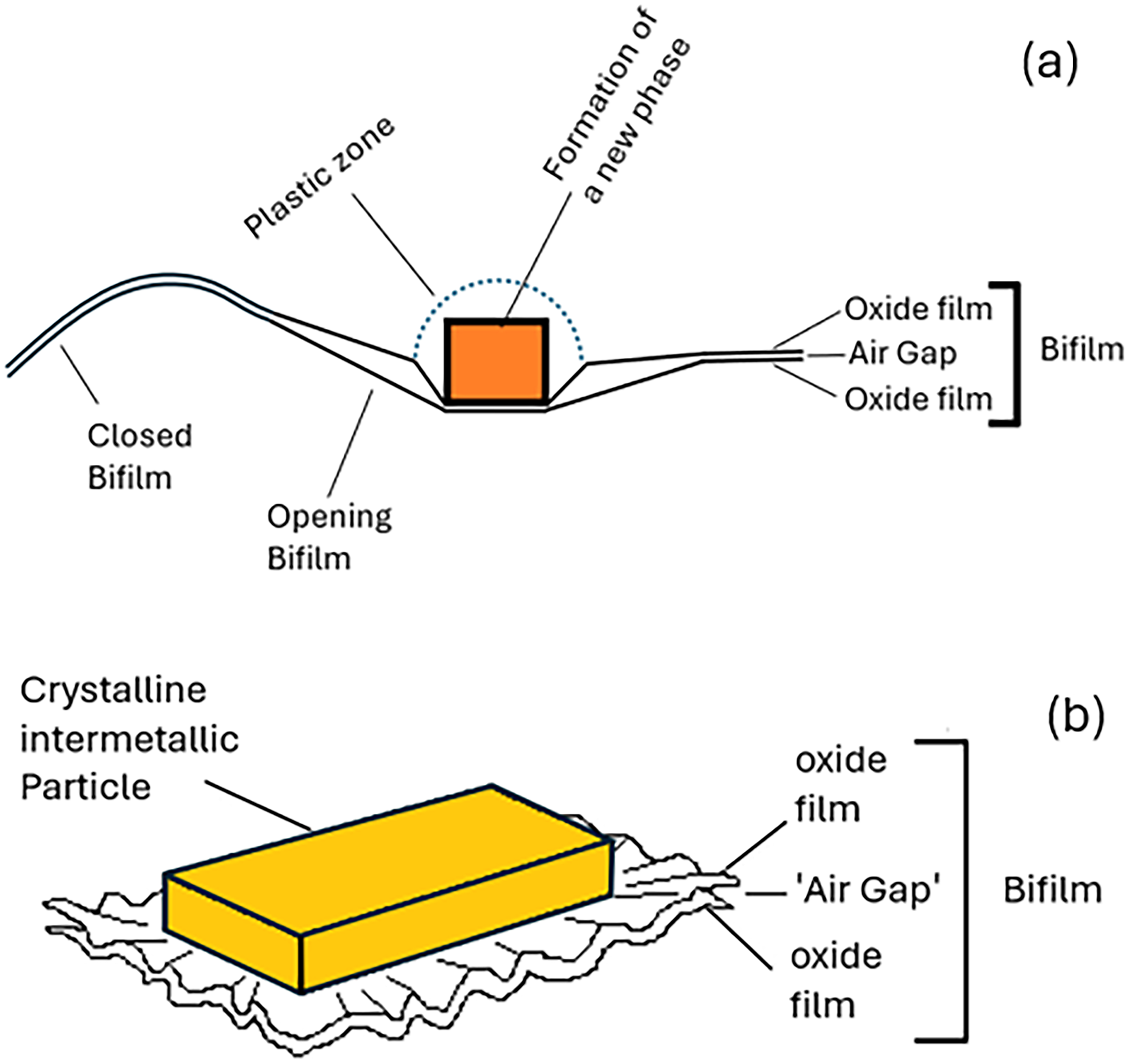
(a) schematic illustration of the nucleation and growth of a new phase on a bifilm, and (b) the expected deformation of the matrix and the bifilm.
The favoured formation of IMCs on bifilms in the liquid seems to be well described by Fan et al., 11 their suggested mechanism relying on the density of the bifilm population. It seems worthwhile to consider the analogous situation in the solid state.
Campbell 12 has provided an explanation for why new phases preferentially form and grow on bifilms in the solid state. The formation of a new phase in the metal matrix strains the surrounding matrix lattice structure because of the volume and shape changes of the new phase, which must be accommodated, resulting in the spreading of a plastic stress zone into the matrix around the new phase as it grows.
In the solid, the creation of plastic zones requires high energy and, therefore, serves as a significant barrier to the formation and growth of new phases in the matrix. In contrast, the ‘air gap’ of the bifilm provides a low-energy deformation location because much of the volume and shape strain of the new crystal can be substantially accommodated in the gap. 12
The gap is partly forced open by the growing precipitate, permitting the strain to be distributed elastically over a large area. In this way an energy-intensive plastic zone in the matrix can be minimised or avoided. A simple mechanical model has been proposed to highlight the potential importance of this mechanism, indicating that accommodating the strain of formation by elastically opening the bifilm results in an energy saving one or two orders of magnitude greater than the energy savings gained from the reduction in net interfacial energies. 12
The energy of formation of the new phase is thereby minimised by the bifilm. In the solid state therefore, new phases will tend to nucleate and grow on bifilms rather than on grain boundaries because of the far greater energy saving. 12
The observation by Yang et al.
10
of
Segregation of bifilms to grain boundaries
In the liquid state, bifilms floating in suspension will be expected to be segregated to grain boundaries during freezing. This is simply because the growing grains will push the bifilms ahead, trapping them between grains as the grains impinge. Thus a significant percentage of bifilms, initially randomly suspended in the metal, automatically become located in as-cast grain boundaries.
In the solid state at high temperature, grain growth or recrystallisation will result in migration of grain boundaries, which, on arrival at a bifilm, will necessarily be pinned in position by the ‘air gap’. New phases will only form at those boundaries which contain bifilms as a result of the high strain energy of formation of new phases. Thus, as observed in practice on a typical polished and etched metallographic sample of a metal, some grain boundaries are decorated with precipitates, whereas other boundaries remain clean.
Furthermore, the distribution of decorated and precipitate-free boundaries seems often to be around 50/50. Thus, the bifilm density in many metals appears to be of the same order as the grain density. If true, bifilms appear numerous and central to metallurgy.
If, as might be expected, this happens in steels, it helps to explain the remarkable persistence of ‘prior austenite grain boundaries’ (PAGBs). 13 The occupying bifilm, together with its precipitates which have widened its ‘air gap’, will ensure the feature is effectively permanent. In contrast, traditional metallurgical thinking commonly assumes that the longevity of the boundary is due to segregation phenomena, and could therefore be diffused away.
The strain of formation accommodated by the particle growing partly into the ‘air gap’ of the bifilm, very slightly prizing open the bifilm and thereby spreading the deformation elastically over a large radial area of the bifilm could explain, for the first time, the formation of the mysterious ‘fish eyes’ observed on fracture surfaces of steels 1 and other metals. The central inclusion, and the surrounding circular area of bifilm which has been forced open are clear in Figure 14.
Turning now to the interesting possibility of eliminating bifilms from liquid metals by sedimentation, if a heavy IMC precipitates on a bifilm, it will sink rapidly. There is now keen industrial interest in this low-energy approach to the cleaning of liquid metals prior to casting.
The pattern of settlement observed in this work is different to that observed by other investigators.15,16 In conditions of a fully liquid alloy over periods up to 20 min, bifilms have been observed to sediment as a horizontal layer on the base of the crucible. In the early exploratory work of Mountford and Calvert 15 their more complex alloy was observed to sediment two separate horizontal layers, presumably the result of different particle/bifilm sedimentation rates of two different particles.
In our experiment, studying the settling behaviour in a casting during only the 2 min available prior to freezing, the simultaneous solidification would have resulted in dendrites growing inwards from the base and the walls during the settling process, tending to nudge the slowly tumbling particles towards the centre, and sometimes arresting their fall, giving the observed final concentration tending to be both central and towards the base. This is expected to be a condition generally experienced in castings.
Conclusions
Findings that bifilms may be the preferred nucleation sites for IMCs are as follows.
1. Intermetallic compounds appear to nucleate and grow on oxide bifilms. 2. An example has been observed of an Fe-rich IMC on one side of a bifilm and an 3. The nucleation and growth of precipitates on bifilms are observed to cause the bifilms to distort. The distortion is predicted to open the bifilms, spreading the strain over a larger area, and so restricting the strain to the elastic, low energy condition, minimising the strain energy of formation of the IMC. 4. The precipitation of intermetallic compounds onto bifilms, especially if the compound is heavy, causes the bifilm and its intermetallic compound to sink. The simultaneous sedimentation of two major metallurgical defects suggests an attractive process route for the upgrading of secondary aluminium alloys during recycling. Some modest extrapolation appears of value (very specifically, not wild speculation(!) but simply employing the aluminium alloy as a model metal for other metals such as steels) 5. Observations corroborate the suggestion
1
that nucleation and growth of intermetallic compounds cannot occur on grain boundaries or in the matrix, but only on bifilms. 6. The scenario suggests a parallel mechanism in steel explaining for the first time the curious fish-eye formation on fracture surfaces. 7. The forcing open of bifilms by precipitates, in turn forcing open grain boundaries, gives a reason for the sensitisation of embrittlement of metals and the stress corrosion of metals by precipitation of particles during sensitizing heat treatment.
1
Footnotes
Acknowledgements:
The authors would like to thank the Republic of Türkiye Ministry of National Education for its financial support.
Declaration of conflicting interests
The authors declared no potential conflicts of interest with respect to the research, authorship, and/or publication of this article.
Funding
The authors received no financial support for the research, authorship, and/or publication of this article.