
Abstract
Solid-state recycling of titanium alloy powder and swarf could improve the sustainability credentials of the aerospace industry, allowing other sectors to benefit from the “low-cost” titanium produced. This study compares the microstructure and crystallographic texture produced when Ti-6Al-4V powder and loose/briquetted swarf are recycled through FAST and HIP. Results show that different microstructures and textures can be achieved through control of the processing temperature. When processed above the beta transus temperature, there are similarities between swarf and powder, processed via FAST and HIP. However, processing below the beta transus results in differences between the swarf/powder and FAST/HIP processed samples. Both techniques can be successfully applied to recycle low-cost titanium swarf, however the pre-briquetting of swarf is recommended.
Introduction
Titanium alloys are utilised by a number of sectors such as aerospace, biomedical and offshore due to their mechanical and physical properties. However, the high cost of titanium prevents these alloys being exploited in other sectors. The cost of a titanium component can be divided into three parts: (1) extraction of the raw material then vacuum melting, (2) thermomechanical processing and (3) machining. Each part represents an approximate 33% of the final cost of the titanium. 1 The Kroll process has been the primary extraction route for titanium sponge since it was developed in 1940 and is a highly energy-intensive and costly process. 2 Many alternative production methods for titanium have been investigated over the years, including; the FFC Cambridge process, 3 the Armstrong process, 4 the MER process, 5 the OS process 6 and the HAMR process. 7 The main advantage of these processes are that they can produce titanium powder directly, at relatively low-cost, although none have been able to achieve the required levels of scale-up to compete with the Kroll process.
In conventional titanium ingot metallurgy, Kroll-derived sponge is melted with the desired alloying elements via vacuum arc re-melting (VAR) or plasma/electron-beam cold hearth melting (CHM). 8 The ingot then goes through as many as 30 to 40 thermomechanical conversion steps to allow the desired microstructure, properties and geometry to be achieved. In many cases the final component requires several machining operations, with up to 95% of some aerospace parts machined away as waste material (swarf/chips). 9
Despite this swarf being high quality and abundantly available, it is currently destined to be either re-melted as revert or exported as ferrotitanium additions for steelmaking. The use of the swarf as an alloying element in steels is a poor example of resource efficiency, since a huge amount of cost and energy was consumed in producing the optimised microstructure of the titanium. As a strategic critical raw material, better utilisation of this titanium waste is highly desired by manufacturers and increasingly mandated by government legislation.
With the increase in popularity of additive manufacturing (AM) processes, there is an increasing amount of waste titanium powder also being produced. AM processes require a specific powder particle size distribution (PSD), which can range from 5 µm to 100 µm. 10 However, powder production processes yield a significant amount of powder particles larger than 100 µm. 11 The rest of the powder is considered oversize and is either stockpiled or re-melted to form new atomization feedstock. Additionally, powder-bed AM techniques require the chamber to be filled with powder but only a small amount of powder is actually melted to create the solid component. Several studies have investigated the reuse of titanium powder in AM. 10 In the study by Tang et al. 12 investigating the reuse of Ti-6Al-4V powder in electron beam powder bed fusion (EBPBF), the oxygen content increased from 800 ppm to 1900 ppm over 21 uses. The quality of the powder also diminished with increasing reuse and the majority of particles were distorted and no longer smooth after 16 cycles.
Oversized powders and machining swarf can be recycled with solid-state processes, such as field assisted sintering technology (FAST) and hot isostatic pressing (HIP). The advantage of using a solid-state process is that the material is not melted, hence, the microstructure can be partially conserved under certain processing conditions. From a sustainability standpoint, re-melting the high-quality swarf or powder material effectively restarts the energy-intensive thermomechanical conversion process, further increasing the amount of embodied carbon. Furthermore, when considering the cost of virgin billet material or powder (≈ £200/kg) to swarf material (≈ £2–10 kg), there is a strong economic argument for the better utilisation of this material through solid-state recycling.
FAST is an emerging technology that uses electrical current to heat the material whilst a uniaxial pressure is applied. The combination of the electrical current and the applied pressure can allow full consolidation to be reached within minutes. The conventional tooling used is made of graphite and one of the major advantages of the process is that it can be reused multiple times. There are several research studies that have used FAST to consolidate titanium powder. Weston et al. 13 processed waste Ti-6Al-4V powder from an AM process and showed that the mechanical properties of the material were similar to conventional material. Kozlík et al. 14 explored the production of a Ti-xNb-7Zr-0.8O biomedical alloy from blended elemental powders by FAST, with compositionally graded Nb content. Nonetheless, there are few studies that have processed oversized titanium powder with FAST. The use of machining swarf in place of powder with FAST has been investigated by a limited number of authors. Weston and Jackson 15 consolidated cleaned machining swarf with FAST, demonstrating that the microstructure and mechanical properties were consistent with conventional wrought material. A similar approach was investigated for the solid-state recycling of Al swarf, 16 Al sheet scrap 17 and Mg swarf. 18 Other solid-state recycling methods for titanium alloys have been explored such as Equal Channel Angular Pressing (ECAP), where Lui et al. 19 investigated the effects of chip conditions on final part properties.
HIP is a more traditional solid-state technology that consists of filling a can with powder and consolidating the powder with a combination of heat and isostatic pressure. With the heat and pressure, the can is deformed until the powder inside is fully consolidated. In comparison with FAST, HIP’ing is more expensive as (1) the encapsulating mild steel can is machined away and cannot be reused and (2) the processing cycles tend to be in the order of hours rather than minutes. However, it is currently possible to make much larger samples with HIP compared to FAST, although industrial FAST machines are increasing in size year upon year. Titanium powder has been commonly used with HIP but there are a very limited number of studies that make use of oversized powders. 20 Similarly, there are no reported studies in the literature surrounding the processing of titanium swarf with HIP, only traditional hot pressing.21,22
The aim of this work is to provide a good understanding of the microstructures and textures obtained from low-cost titanium feedstock when processed with FAST and HIP. Furthermore, two different routes of processing swarf will be explored, processing loose swarf directly and cold briquetting of loose swarf before processing.
Materials and methods
Materials
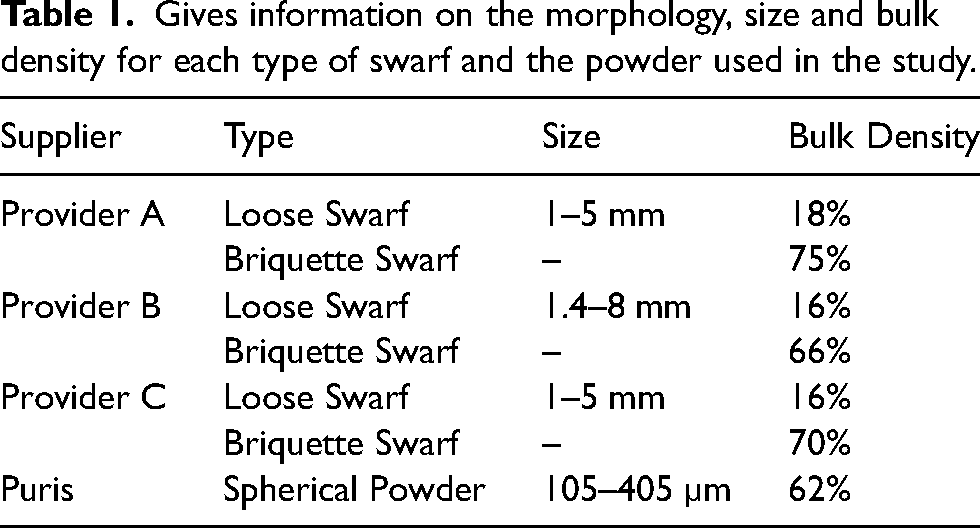
This work is focused on the use of alloy Ti-6Al-4V from two different feedstock: swarf and powder. The powder used was oversized gas atomised (GA) powder manufactured by Puris LCC, Bruceton Mills, WV, USA, details regarding the PSD and morphology are given in Table 1. The swarf was produced during machining of titanium components at different stages of the production process. To avoid contamination with impurities and the lubricant used during machining operations, the swarf was cleaned by Transition International Ltd, Sheffield, UK. The swarf was originally produced by three different manufacturers, which will be referred to as Provider A, Provider B and Provider C. The morphology of the swarf for Provider B and Provider C were discontinuous, flat chips in both cases, however, Provider A had a slightly more ribbon-like morphology.
Gives information on the morphology, size and bulk density for each type of swarf and the powder used in the study.
The chemical composition of the swarf and the powder is shown in Table 2. The composition was measured after the swarf had been through a heavy wash process. A Perkin Elmer Avio 200 ICP optical emission spectrophotometer (ICP-OES) was used to measure the composition of 2 g of Ti, Al, V and Fe. The O and N composition was measured from a 50 g sample with an Eltra Elementrac ON analyser and the C was measured from a 500 mg sample with an Eltra CS800 analyser.
Chemical composition of the swarf and powder used in this study in wt.%.
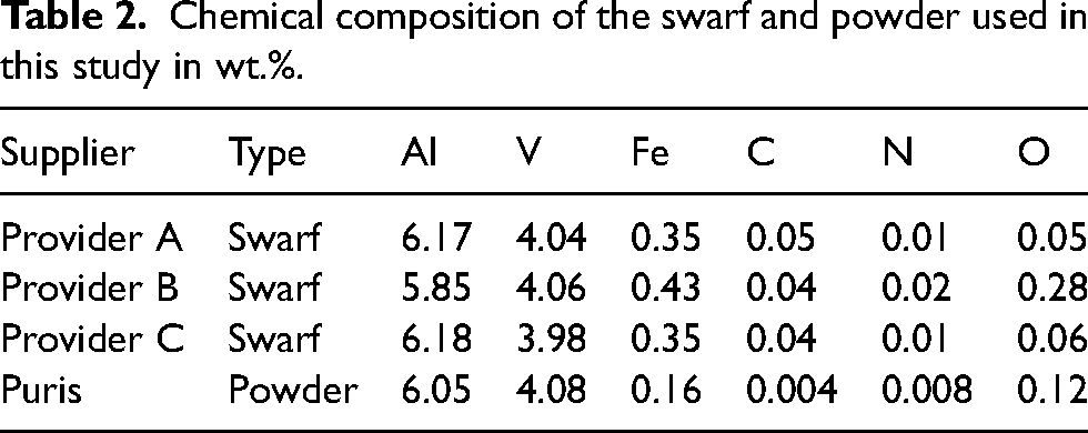
Figure 1 shows the initial microstructure of the swarf after etching with Kroll's reagent under Light Optical Microscopy (LOM) and Scanning Electron Microscope (SEM) micrographs with Backscattered electrons. The Provider A and Provider B swarf has a saw-edge like morphology (Figure 1(a, c)) while the Provider C swarf is slightly thinner and flatter (Figure 1(e)). Provider A has a fully equiaxed microstructure consisting of primary α grains (Figure 1 (a, d)). The Provider B turnings (Figure 1 (b, e)) show a bimodal microstructure consisting of primary α grains and transformed β. Moreover, there are isolated regions of globular α and transformed β observed suggesting that these turnings consist of a combination of mill anneal and β anneal forgings. Swarf from Provider C shows a fully lamellar microstructure (Figure 1 (c, f)) suggesting it is in the β annealed condition.
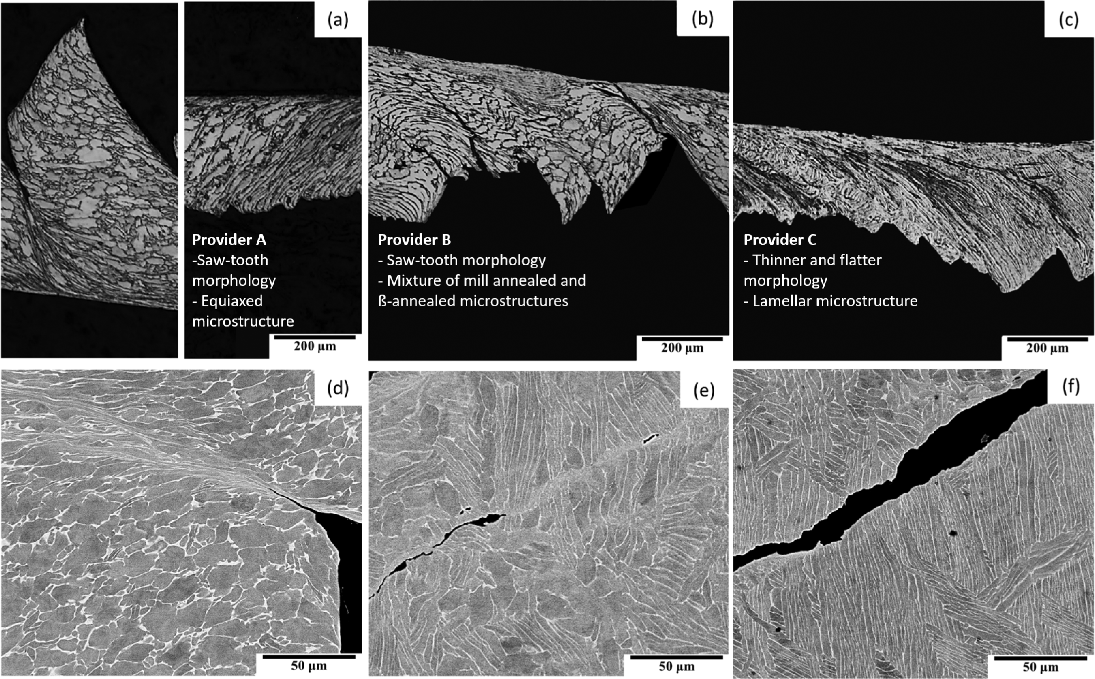
Light optical micrographs (a–c) and backscattered electron micrographs (d–f) of the initial microstructure of loose swarf from provider A (a, d), B (b, e) and C (c, f), respectively.
The swarf was also provided in a briquetted form, where the swarf had been cold pressed to high pressures to deform it and obtain a green body with a desired shape. The shape of the briquettes was a simple cylinder with a diameter of 32 mm and a total of 40 g of swarf (see Figure 2).
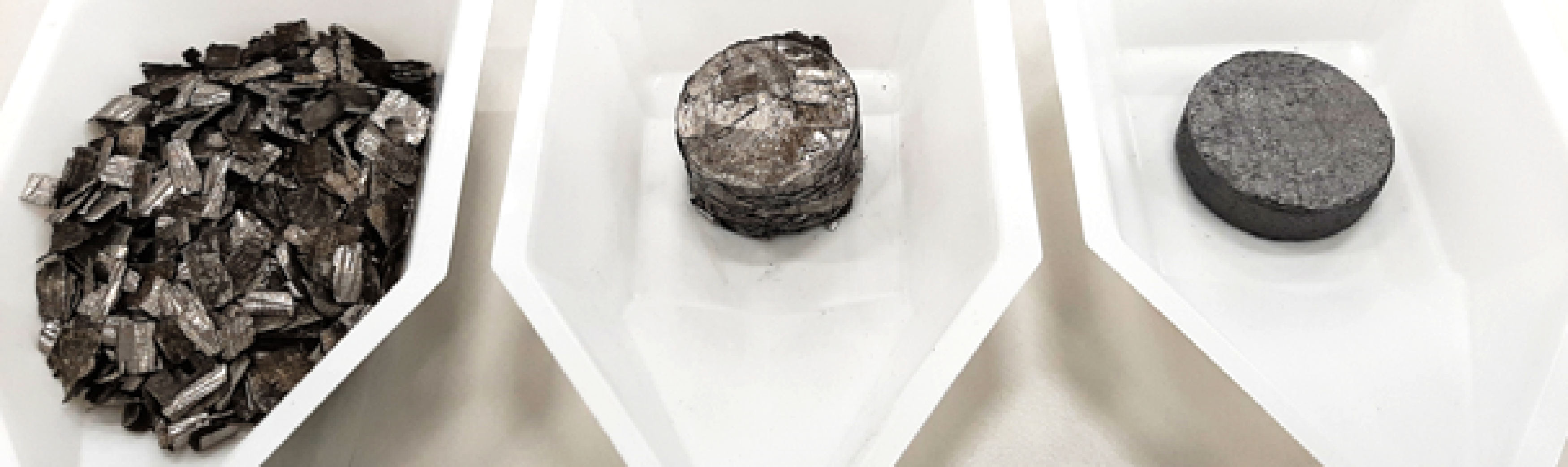
Photograph showing 40 g of Provider B (from left to right) loose swarf, 32 mm briquetted swarf and 35 mm FAST processed swarf.
Figure 3 shows the microstructure and geometry of the briquetted swarf under LOM. The large number of turnings covered by each micrograph allows the distribution of the turning microstructure within a briquette to be investigated. All briquettes showed a heavily deformed microstructure, which is very clear in Figure 3 (c, d). Overall, the briquettes manufactured from Provider A and Provider C show a homogeneous microstructure (Figure 3 (c, d, e, f)) while the briquette from Provider B shows a variety of microstructures consisting of fully lamellar, bimodal, and fully equiaxed turnings (Figure 3 (a, b)). Contrastingly to the microstructure of the Provider C swarf in Figure 1 (c, f), the Provider C briquette (Figure 3 (e, f)) shows a heavily deformed microstructure of α laths that are broken up by the deformation induced possibly from the cold pressing briquetting stage.
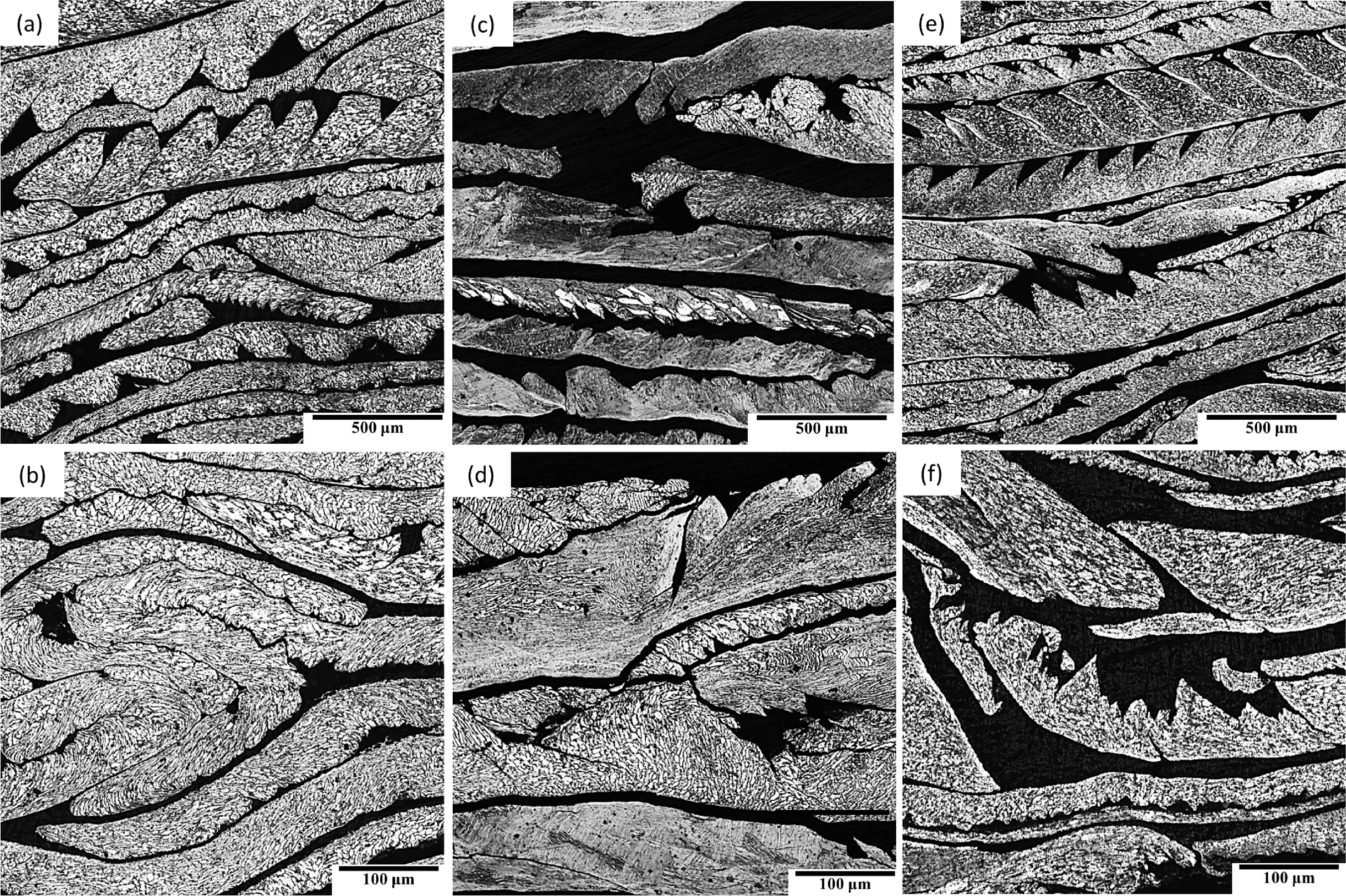
Light optical micrographs of the microstructure of the swarf briquettes from Providers A (a–b), B (c–d) and C (e–f).
The bulk density of the swarf from each provider was calculated by obtaining the ratio of the mass to the volume after tapping using a graduated cylinder in comparison to the value for a sample of full density. The tapping was performed by slightly pressing the swarf into the container manually and adding more turnings until the starting volume was achieved. The bulk density values for the three turning providers are between 16 and 18%, whilst the briquette density values are between 66 and 75%. The same process was used to measure the bulk density of the powder. The density of the briquettes was measured by measuring the size and the weight of the briquettes and comparing the ratio of mass and volume with the ratio obtained for a fully dense sample. All of the densities are shown in Table 1.
FAST
The powder, loose swarf and swarf briquettes were consolidated in a FAST Furnace Type HP D 25 (FCT Systeme GmbH, Germany), at the Royce Discovery Centre, University of Sheffield. The final sample dimensions were 35 mm diameter by approximately 10 mm height from 40 g of both Ti-6Al-4V loose and briquetted swarf. The powder was processed with 20 mm diameter tooling and the total mass used in each run was 23 g. In all cases, cylindrical graphite tooling was used.
The FAST processing conditions were the same for all runs except for the dwell temperature. The heating rate was always 100°C/min with an applied pressure of 35 MPa and a pulse current of 15 ms on and 5 ms off. The dwell time was 30 min and the dwell temperature was 950°C or 1100°C, i.e., below or above the β transformation temperature of Ti-6Al-4V. For the cooling stage the power was switched off and the sample was left to cool down to room temperature, with an average cooling rate of 2°C/s, before being removed from the machine.
HIP
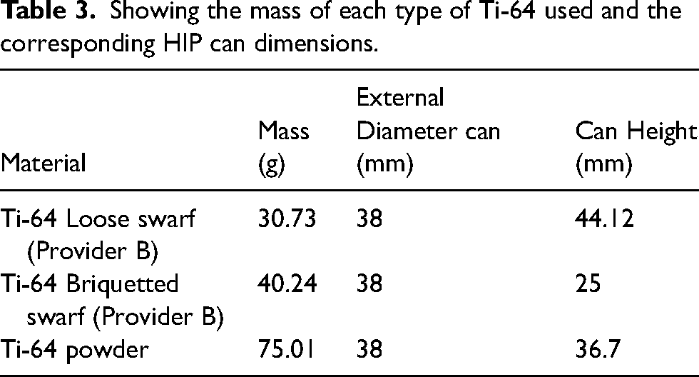
The HIP study focused on processing the powder, the loose swarf and swarf briquette from Provider B. The hot isostatic press used was an AIP8-45H (AIP, USA), at the Royce Translational Centre, University of Sheffield. The cans were produced at the University of Sheffield. The can material was 316 stainless steel with a diameter of 35 mm and variable height. Table 3 presents the mass of material and the exact dimensions of the can for the three samples processed.
The process to fill the cans with powder or swarf consisted of adding a quarter of the total material before applying 2 tonnes of force for 2 min with a 25 tonnes press. This allowed the initial packing density of the swarf or powder to be improved. Although this method worked well with powder, it had little effect on compacting the loose swarf due to the strength of the material. Furthermore, it was not possible to apply a higher pressure without damaging the can. No pressure was required for the briquette since it had already been cold pressed. Once the can was filled, the top lid and evacuation tube was welded to the HIP can before degassing.
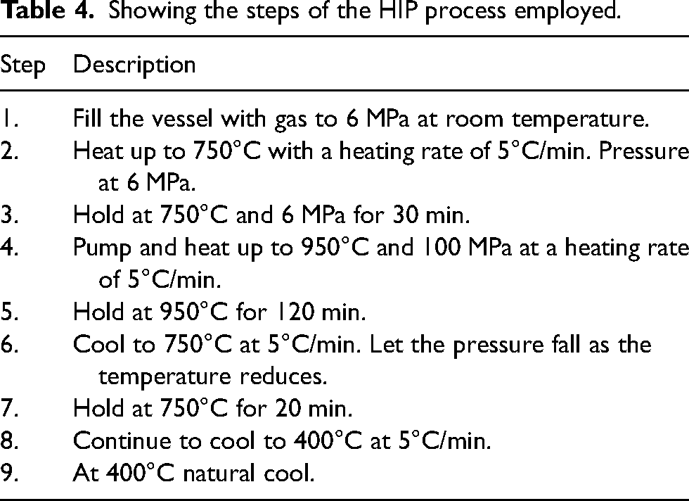
The HIP processing route is shown in Table 4. The dwell temperature was 950°C and the dwell time was 120 min. A maximum pressure of 100 MPa was reached during dwell. Furthermore, the heating and cooling was applied at a controlled rate of 5°C/min to avoid failure of the can through deforming too rapidly.
Showing the mass of each type of Ti-64 used and the corresponding HIP can dimensions.
Characterisation
The analysis of microstructure and texture in all samples was performed in the longitudinal cross section. For optical microscopy, the specimen surface was ground using SiC grit paper from P400-P4000 grit, polished for 15 min with colloidal silica 0.06 µm and 10% H2O2, and etched using Kroll's reagent to reveal the microstructure. Micrographs and density of the consolidated samples were obtained using an Olympus Bx51 with a Clemex Vision PE image analysis system. The texture analysis was performed by electron backscattered diffraction (EBSD) in a JEOL 7900F scanning electron microscope (SEM) equipped with a Symmetry detector for orientation data acquisition using AZtecHKL. Low-resolution EBSD was performed covering areas of 2 × 2 mm2 using a 5 µm step size. Post-processing of the texture data was performed using the open access MTEX 23 software for orientation mapping and pole figure plots. Only the HCP α-phase of titanium was selected for texture analysis. Unless otherwise stated, the inverse pole figure (IPF) orientation maps are coloured regarding AD and the pole figure plots are shown with AD in the centre. Hardness values were obtained using a Durascan 70 G5 microhardness indenter with a load of HV5 and a dwell time of 15 s per indent.
Results and discussion
The microstructure of the powder samples processed with FAST and HIP after being etched with Kroll's reagent are shown in Figure 4. All three micrographs demonstrate that there are no visible pores or defects at the sample surface. The powder processed in the α+β region (950°C) produces an equiaxed primary α microstructure with transformed secondary α with a lath-type morphology, for both FAST and HIP. The powder processed with HIP has a slightly coarser primary α size, due to the longer dwell time at maximum temperature. The powder processed with FAST in the β region (1100°C) produces a fully lamellar microstructure with fine α laths in the colonies and a low fraction of grain boundary α around the prior β grain boundaries.
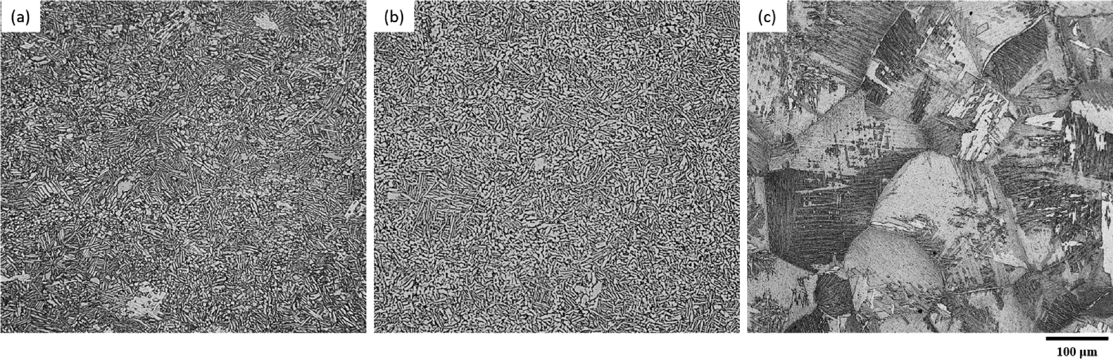
Light optical micrographs of powder processed at 950°C with (a) FAST and (b) HIP and (c) at 1100°C with FAST.
The microstructure of the powder produced with FAST can be compared with the microstructure of processed swarf shown in Figure 5. This figure shows the microstructure of the swarf from the three different providers, processed above and below the β transus temperature of Ti-6Al-4V, when loose or briquetted swarf is used as an initial feedstock.
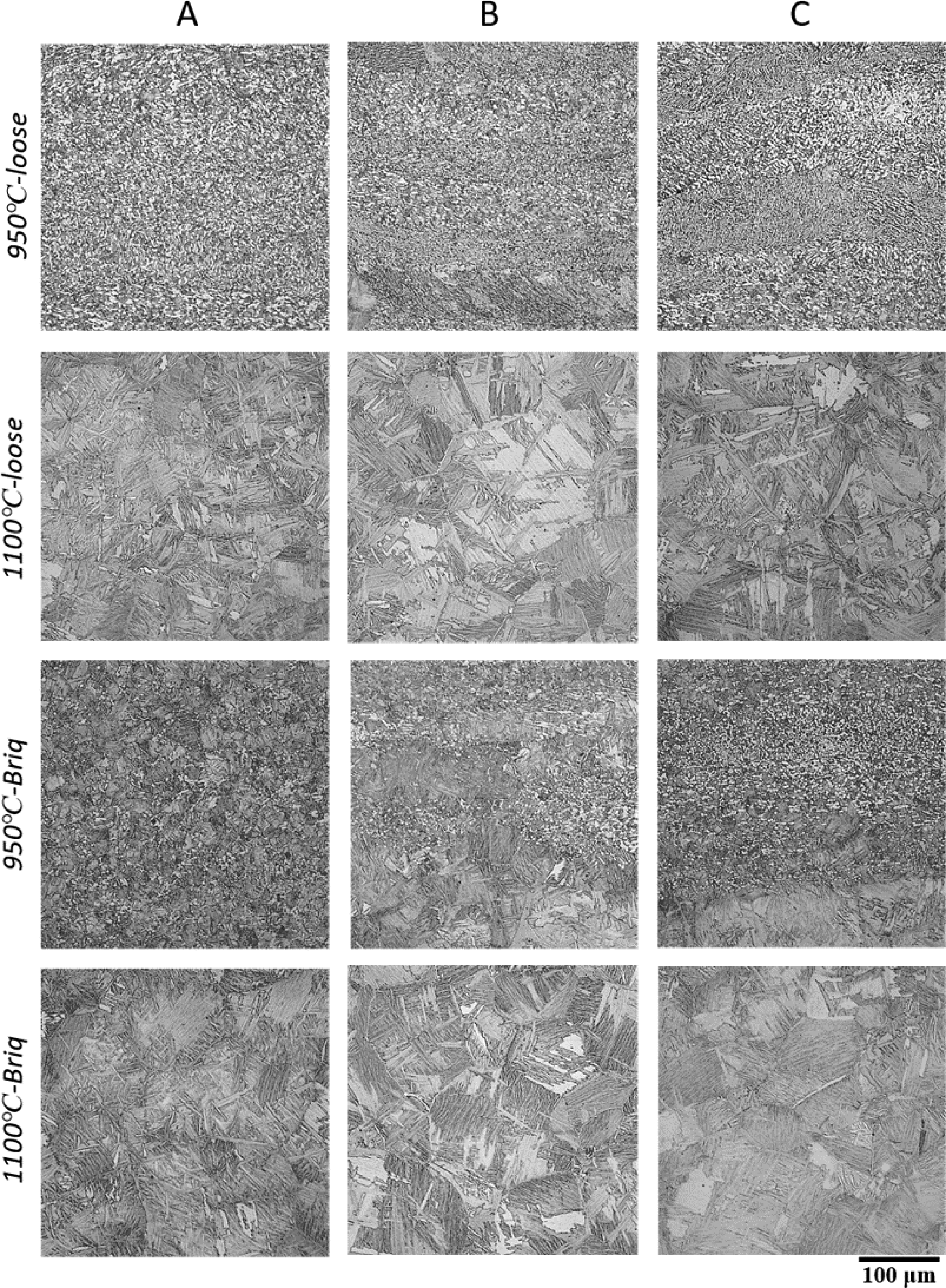
Light optical micrographs showing the microstructure of consolidated swarf from each provider, loose and briquetted, when processed below and above the β transus temperature.
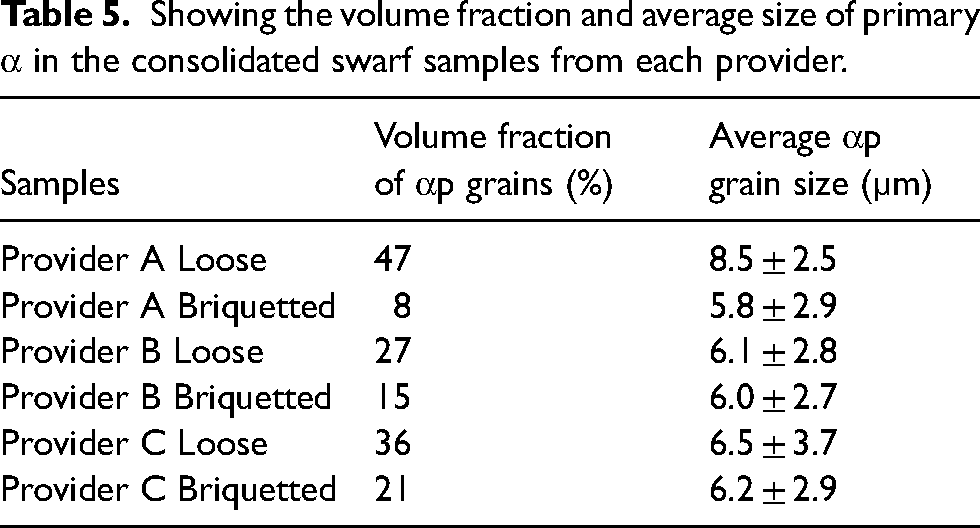
Overall, Figure 5 demonstrates that loose swarf processed below the β transus (Tβ) shows a heterogeneous microstructure consisting of horizontal bands of microstructural features that are perpendicular to the compression direction during sintering and the pre-pressing stage (vertical on the page). Such bands are caused by the individual swarf chips/particles that maintain their individual characteristics, even though the particles have bonded together into a fully consolidated sample. All of the microstructures show a bimodal microstructure of primary α grains and secondary α colonies. These samples show a relatively high-volume fraction of α grains, with Provider A having the highest and Provider B the lowest, as shown in Table 5. The primary α grains are heavily deformed in all samples due to the machining process. The direction of deformation and the size of the primary α grains changes from region to region suggesting that the influence of each individual turning is still present after processing below Tβ. This is particularly prominent in the Provider C sample.
Showing the steps of the HIP process employed.
Contrastingly, the heterogeneous bands were not observed when the loose swarf was processed above Tβ, instead the micrographs from the samples processed at 1100°C in Figure 5 show a homogeneous fully lamellar microstructure, typical of a sample processed in the β region.
When processing briquetted swarf below Tβ, the bands are not as pronounced as for loose swarf for Provider A and Provider C swarf. However, the banding is similar for Provider B swarf regardless of loose or briquetted feedstock. Furthermore, the volume fraction of primary α grains in the bimodal microstructure is drastically decreased for briquetted swarf. These α nodules are evenly distributed for the Provider A briquettes, which also shows the smallest colony size. The bimodal microstructure of samples Provider B and Provider C have a larger colony size and a heterogeneous distribution of primary α grains, creating regions of agglomerates of primary α grains and regions of a mainly transformed microstructure. These regions of agglomerates could be related to the previous strain path history of the swarf material.
As previously observed for loose swarf, a homogenous fully lamellar microstructure is observed in all the briquette samples when processed above Tβ. The size of the prior β grains of the briquette samples are smaller than the grains generated with loose swarf or powder.
The average hardness of the samples shown in Figure 5 are presented in Table 6. The average hardness values vary less between the providers when briquetted swarf is used compared to loose swarf. For loose swarf processed at 950°C and 1100°C the difference between the maximum and the minimum values recorded are 23 and 45 HV5, respectively. In comparison, when the feedstock is briquettes, this difference is 14 HV5 and 20 HV5, respectively. These results correlate well with the microstructures presented in Figure 5 where a more consistent microstructure is observed for briquetted swarf. Furthermore, processing below the β transus tends to generate lower hardness levels than when processing above the β transus. Finally, the hardness of the Provider B tends to be higher than the rest of the providers, which could be due to the higher oxygen content of the initial swarf, as presented in Table 2.
Showing the volume fraction and average size of primary α in the consolidated swarf samples from each provider.
Showing the measured hardness values and measured density for FAST consolidated swarf, loose and briquetted, from each provider.
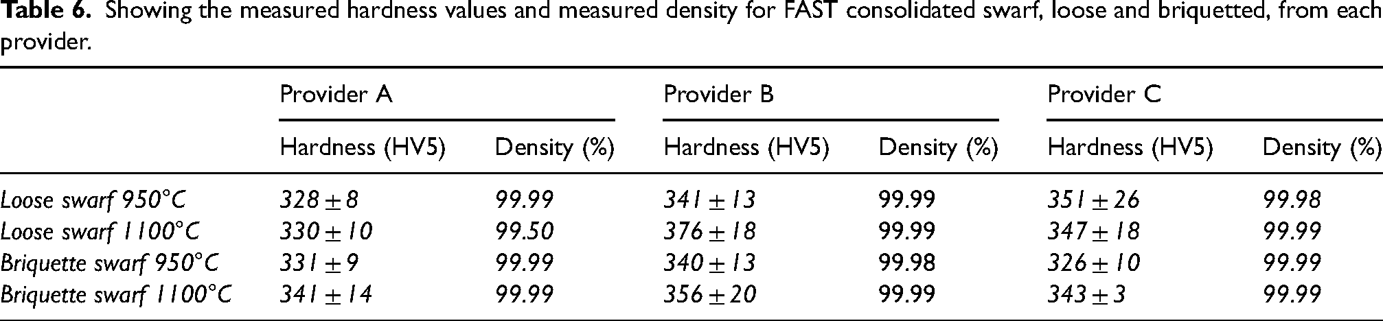
The density of the consolidated samples is also presented in Table 6. The results show that full densification is achieved with FAST independently of the processing temperature or swarf provider. The Provider B loose swarf processed at 1100°C had a lower density than the rest of the samples. This was due to an impurity in the sample that dissolved during the etching process resulting in a void.
Texture analysis of the different Ti-6Al-4V feedstock processed from powder and provider B swarf (loose and briquetted) via FAST
The swarf from Provider B was chosen for further analysis of the textural differences between briquetted swarf, loose swarf, and powder. Since the microstructure and hardness is similar for all the swarf providers, it was not expected to see major textural differences between them.
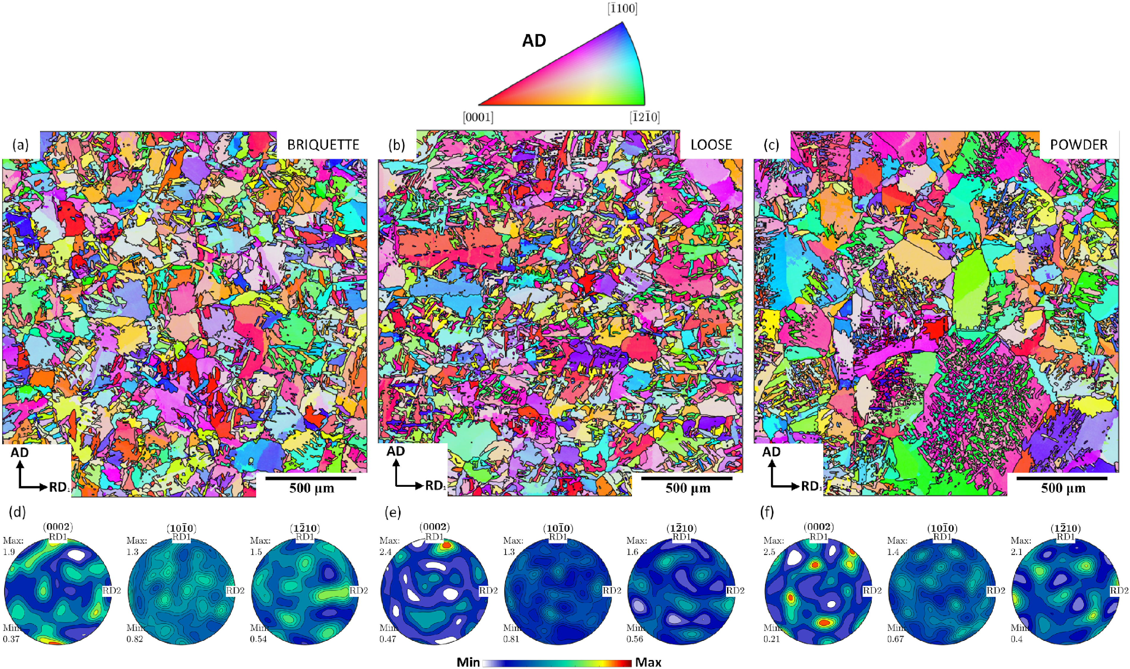
Inverse pole figure (IPF) maps and pole figure plots are shown in Figure 6 and Figure 7 after processing briquetted swarf, loose swarf and powder with FAST at 950°C and 1100°C. When processing below the β transus temperature, at 950°C, briquetted (Figure 6(a)) and loose swarf (Figure 6(b)) show a strong texture with microstructural features horizontally aligned sharing similar crystallographic orientation. These band-like features appear to be directly related with the swarf particles of the starting feedstock material whose texture remains after processing at this temperature. Regions between the band-like features are clusters of recrystallized grains. The amount of recrystallized grains in the areas analysed here are about 29% for loose swarf and 44% for the briquette swarf sample. The higher percentage of recrystallized grains in the briquetted swarf sample might be a result of the extra deformation induced during the cold briquetting process compared with loose swarf. Both swarf samples showed a relatively strong basal texture displayed by {0002} poles aligned with AD (Figure 6(d,e)). Contrastingly, when processing powder under the same processing conditions there is a predominant but weak compression texture with the basal poles randomly distributed mainly around the radial directions (Figure 6(f)). No clusters or features similarly orientated are observed in the orientation map, Figure 6(c).
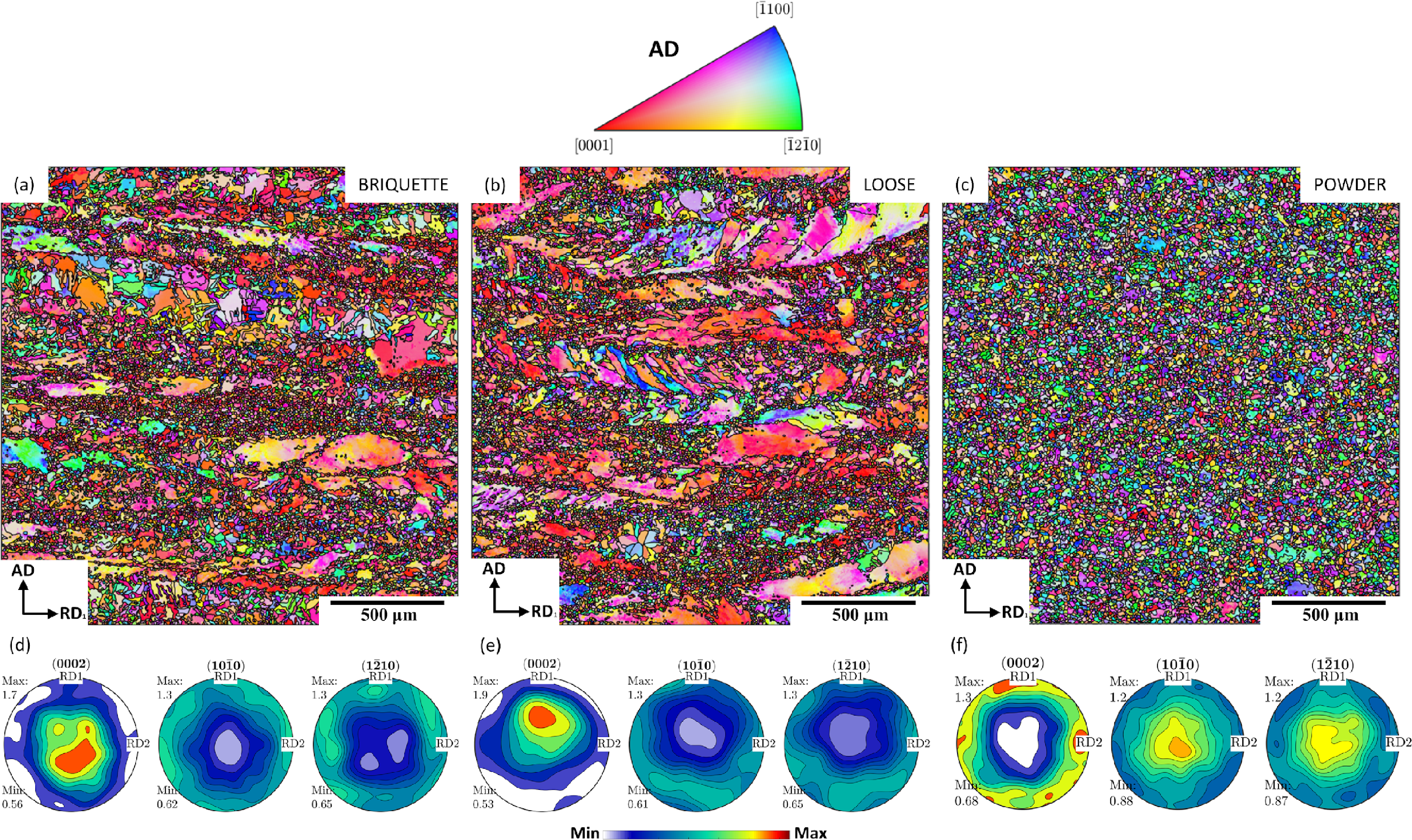
IPF orientation maps with respect to AD and corresponding pole figures after processing Ti-6Al-4V via FAST at 950°C using (a, d) briquetted swarf, (b, e) loose swarf and (c, f) powder feedstock.
IPF orientation maps with respect to AD and corresponding pole figures after processing Ti-6Al-4V via FAST at 1100°C using (a, d) briquetted swarf, (b, e) loose swarf and (c, f) powder feedstock.
When increasing the processing temperature above the β transus, at 1100°C, the band-like features observed in loose and briquetted swarf are completely removed (Figure 7 (a, b)) and the pole figure plots show a random texture with low intensity peaks with no preferential alignment with any pole. The main difference is the larger grain size observed when processing powder compared to swarf.
Comparative microstructure and texture analysis on Ti-6Al-4V feedstock processed from powder and provider B swarf (loose and briquetted) via HIP at 950°C
The microstructure and texture of the three HIP’ed samples was analysed, with initial feedstock of powder, loose swarf and briquetted swarf. Figure 8 shows the cans after HIP processing (a-c) and after de-canning by machining (d-e). Figure 8 (a,d) shows the can used to consolidate the powder. The level of deformation around the circumference of the can is constant, with some deformation to the top and bottom of the can also, which is typical of powder HIP processing. However, when processing loose swarf (Figure 8 (b,e)) a large non-axisymmetric deformation of the can is observed, which causes the material inside to deform the same way. Finally, the can that contained the briquetted swarf (Figure 8 (c,f)) shows similar deformation characteristics to the powder sample, although there was some limited heterogeneous deformation of the can observed.
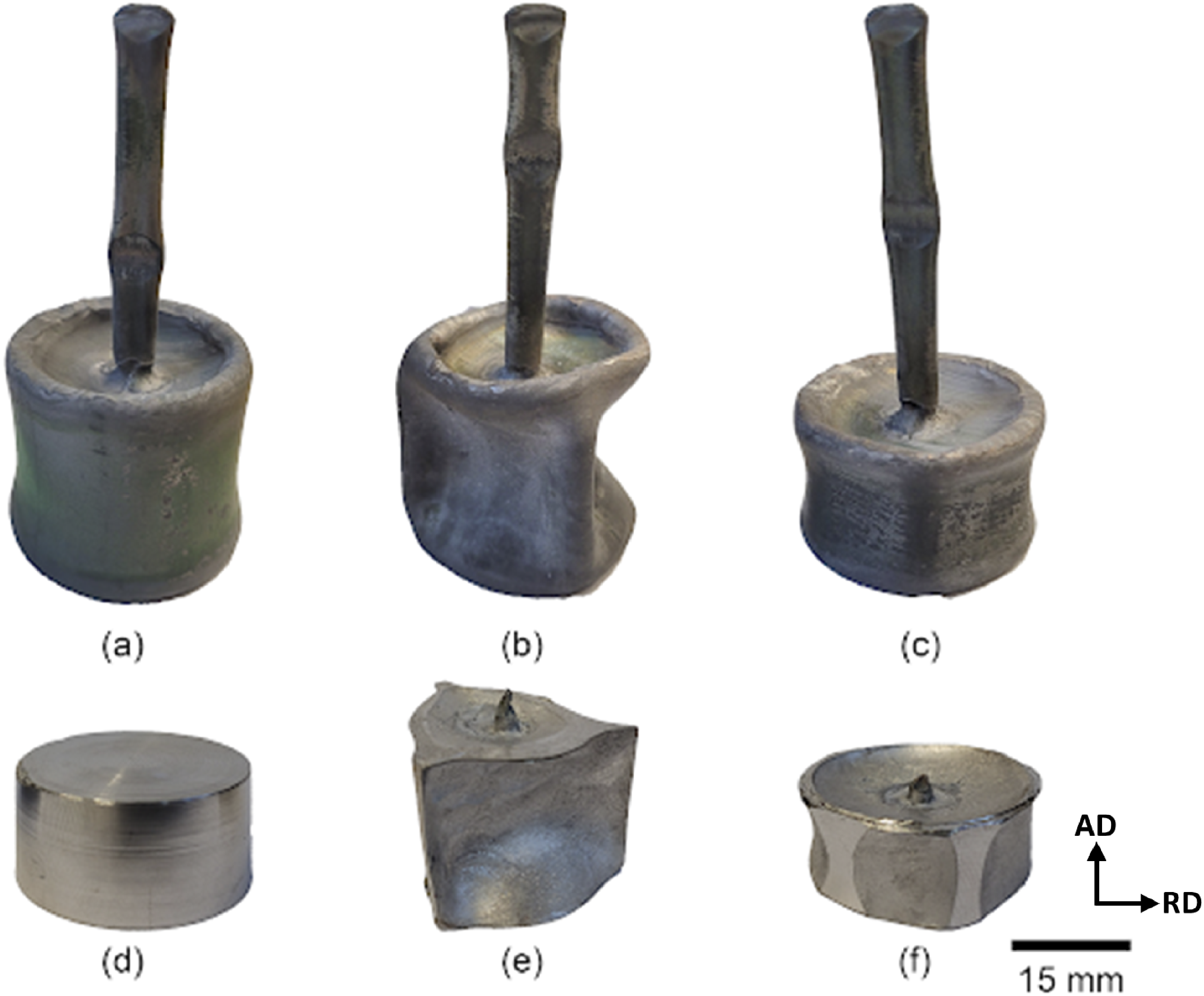
HIP samples after processing inside the HIP’ing can (top) and after can removal by machining (bottom) of Ti-6Al-4V (a) powder, (b) loose swarf and (c) briquetted swarf.
The microstructure of each of the three HIP samples are shown in Figure 9. All three samples have a predominantly equiaxed primary α microstructure, with some regions of α colonies which prior-existed in the swarf particles. The samples produced from loose swarf (Figure 9(a-b)) and briquetted swarf (Figure 9(c-d)) show evidence of microstructural variation between different swarf particles through varying primary alpha size and morphology. The sample produced from powder in (Figure 9(a-b)) shows the largest primary α grains and some regions of transformed β. No porosity or defects were observed in any of the three HIP samples.
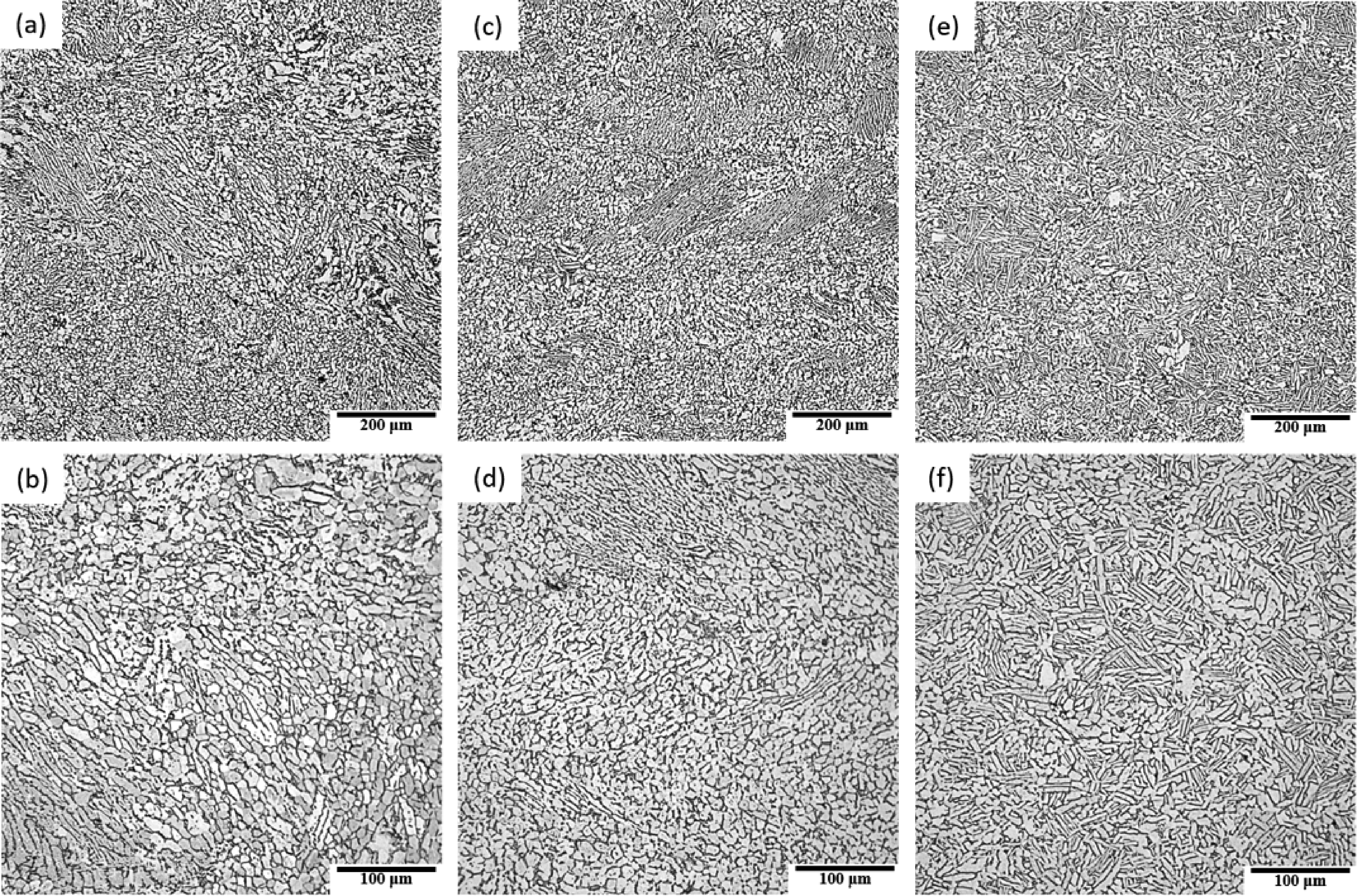
Light optical micrographs showing the microstructure of HIP samples after processing (a) loose swarf, (b) briquetted swarf and c) powder.
The IPF orientation maps and corresponding pole figures of the HIP samples, consisting of briquetted swarf, loose swarf and powder processed at 950°C, are shown in Figure 10. At this processing temperature, as observed in FAST (Figure 4) band-like features inherited from the swarf particles are still present (Figure 10 (a, b)). However, whilst the band-like features are horizontally aligned for the sample using briquetted swarf (Figure 10 (a)) similar to with FAST, when processing loose swarf these bands are deformed differently, in several directions. This is a result of the nature of the HIP process where the pressure is applied in all directions, therefore deforming the can heavily as well as the material inside (with a low initial bulk density). The amount of recrystallized grains in the areas analysed for HIP’ed swarf material is around 26% for loose swarf and 42% for the briquette swarf sample. The pole figure plot for the briquetted swarf sample shows the same basal texture aligned with AD as previously observed for this feedstock in FAST (Figure 6 (d)). For loose swarf, this high density peak prevails but is no longer aligned with AD. On the contrary, HIP’ed powder showed a random texture as shown in Figure 10 (c, f). The main difference between the powder processed with FAST and HIP is that although the texture seems to be random in the IPF map the pole figures are noticeably different as a result of how the pressure is applied during the consolidation process, which as previously shown, gives a weak compression texture for FAST (Figure 6 (f)) while a completely random texture for HIP (Figure 10(f)).
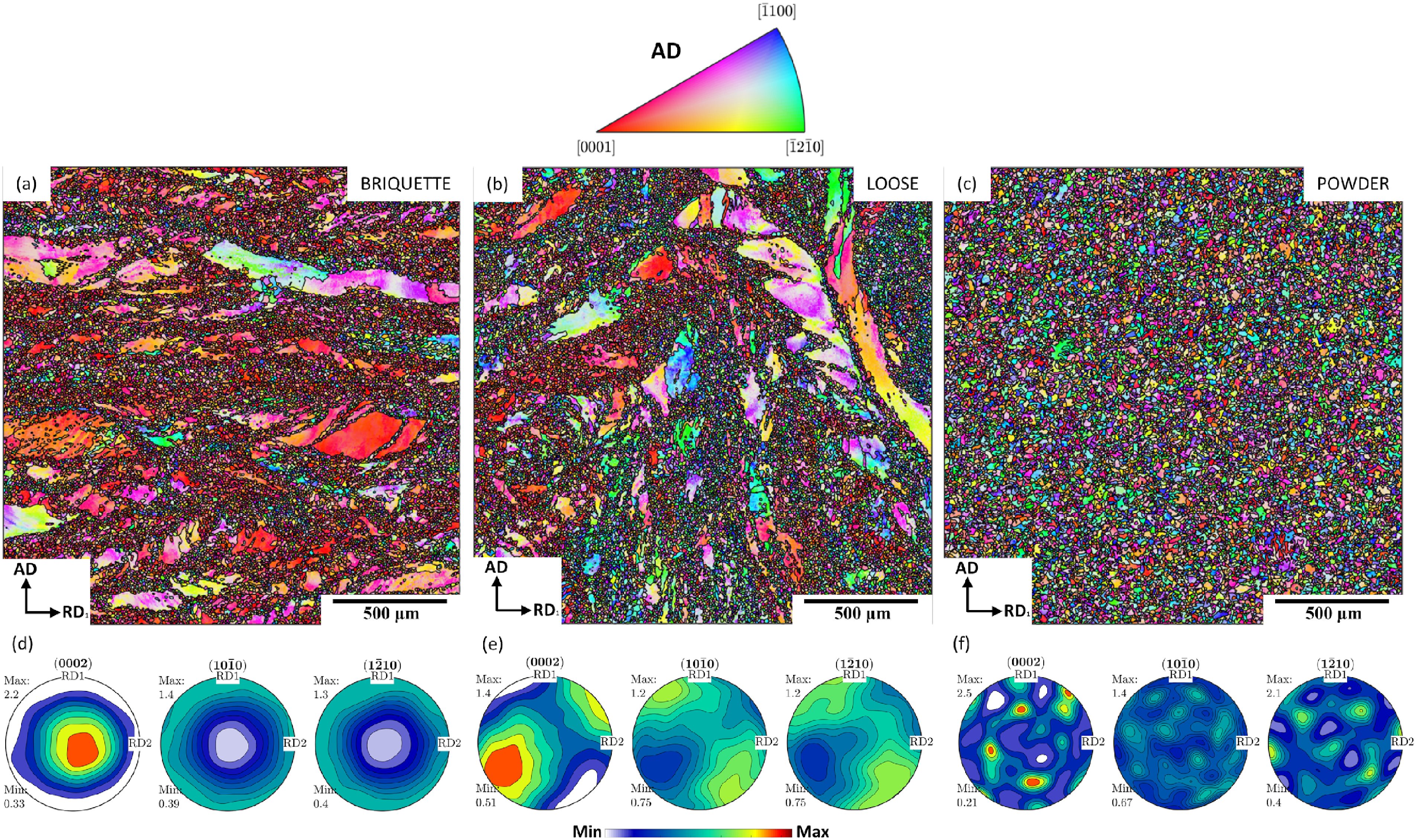
IPF orientation maps with respect to AD and corresponding pole figures after processing Ti-6Al-4V via HIP at 950°C using (a, d) briquetted swarf, (b, e) loose swarf and (c, f) powder feedstock.
Discussion
The initial microstructure of the powder is martensitic due to the rapid cooling rates experienced in the gas atomisation process. After processing below the β-transus temperature, with FAST or HIP, a fine-equiaxed α microstructure is observed in both cases. During processing the martensitic α’ needles decompose/recrystallise to form primary α nodules and experience limited growth during the dwell time at temperature. When processed above the β-transus, rapid grain growth occurs during FAST processing, with the largest prior-β grains seen in the sample produced from powder. This is due to the lower dislocation content in virgin powder when compared to swarf which has been heavily deformed, therefore having less resistance to grain growth. Limited grain boundary α is observed along the prior-β grain boundaries for both powder and swarf when compared to other studies, this can be attributed to the relatively fast cooling rates experienced by FAST samples of this size (≈ 2°C/s).
When comparing the microstructure of FAST processed loose and briquetted swarf similar microstructural features are seen including maintenance of the initial swarf microstructure and areas of recrystallisation, when processed below the β-transus. This effect could be manipulated in future through close control over the input feedstock, for example a homogeneous billet could be produced by ensuring all of the swarf came from the same forging and/or condition. Similarly, Ti-6Al-4V swarf in different material conditions could be selectively deposited in different regions of the mould to achieve a composite microstructure. The “horizontal banding” effect is seen perpendicular to the compression direction in both cases. Depending on the application, the strong basal texture produced as a result of this banding may be seen as beneficial, for example in ballistic applications as demonstrated by Silva et al. 24 The amount of recrystallized grains is around 15% higher for briquetted swarf than loose, it is suspected that this is due to the extra deformation experienced by the swarf during the briquetting process. The generation of this fine-grained structure is very desirable for some applications, in fact a combination of both fine and larger grains has been termed a harmonic structure which produces superior mechanical properties, as reviewed by Amayema et al. 25
In terms of microstructure, there is little differences observed between swarf processed with FAST and HIP, with varying primary alpha size and volume fraction in different regions due to the characteristics of the different swarf particles. The HIP processed swarf produced a more equaixed α microstructure compared to FAST which produced a mixture of equiaxed and bi-modal microstructures. Although this may be related to the swarf input and not inherent to the process, since only swarf from Provider B was processed with HIP. When comparing the two samples produced from powder below the β-transus, the HIP sample shows a coarser microstructure owing to the longer time at temperature and slower cooling rate.
Differences in the crystallographic texture of FAST and HIP processed samples can be explained by the different compression axis that the feedstock experiences during consolidation. For example, FAST processed powder has a weak compressive texture owing to the uniaxial force applied during sintering, whereas HIP processed powder has a completely random texture since the pressure is isostatic. For loose swarf, FAST produces a strong basal texture aligned with AD, again due to the compression direction. HIP produces a similar strong basal texture however it is no longer aligned with AD, the alignment will depend on the deformation of the can and this may not be easily controlled in a repeatable manner. However, with the addition of a cold-briquetting step both HIP and FAST show the same strong basal texture aligned with AD. This suggests that the texture of a HIP component could purposely be manipulated through careful briquette and can design.
The large amount of deformation observed in the HIP can with loose swarf is caused by the low initial density of the swarf. As shown in Table 1, the bulk density of the swarf used is around 20%. Consequently, the can has to deform considerably to counteract the 80% of porosity inside the can. The main solutions to this problem are to fill the empty spaces (with powder or finer swarf) or to compress the swarf together. It is possible to crush the swarf into smaller particles but crushing swarf smaller than 1 mm is an energy intensive process. Additionally, fines also tend to oxidise easier and present an increased fire risk, due to the large surface area. Therefore, the best solution is to pre-briquette the swarf, as the results show that it consolidates well with HIP. The slightly heterogeneous deformation of the can was caused by the briquette used in this study having an outer diameter of 33 mm, whereas the can had an internal diameter of 35 mm. With a larger briquette (e.g., 34.5 mm OD) it is likely that the deformation around the can would have been consistent as was observed with the powder HIP can.
The low bulk density of loose swarf is less of an issue with FAST since the deformation is uniaxial. However, the low initial density does limit the maximum final height of the sample which can be produced due to two reasons; the size of the mould (limited by the size of the vacuum vessel) and the maximum travel of the pressing piston/electrode in the machine. In this way, pre-briquetting of the swarf allows for more material to be processed in one cycle and allows taller samples to be produced. The use of briquettes has also proved to be beneficial for die wear and reducing carbon contamination at the edge of the sample. Firstly, since briquetted swarf tends to have smoother edges than the aggressive, sharp edges of individual swarf particles and secondly, without briquetting there is a lot of travel and the sharp swarf “pinches” the graphite foil lining and pulls it inside the perimeter of the sample. There are perhaps further potential benefits to briquetting swarf through the increased levels of recrystallised grains observed as discussed previously, although how this can be achieved in a repeatable manner needs to be further understood. The direction of FAST research from academia and industry alike is towards larger billets meaning briquetting will play a key role if low-cost titanium billets of an industrially-relevant scale are to be produced from swarf. A greater understanding of the briquetting process itself will also need to be developed to understand the influence of swarf size/morphology and the pressing loads required to produce briquettes of sufficient size.
In the authors’ view, there will be future industrial applications for the solid-state recycling of swarf via both FAST and HIP, depending on requirements such as; shape, size, texture and microstructure. From a cost-perspective, FAST has the advantages of re-usable graphite tooling and shorter processing times compared to HIP, which requires destructive removal of the steel can after processing. However, currently HIP has been demonstrated for much larger and complex-shaped geometries (with powder) and therefore, the most likely outcome is that both technologies can co-exist as part of the titanium recycling ecosystem.
Conclusions
Overall, this study has demonstrated the successful consolidation of low-cost feedstock including; powder, loose swarf and briquetted swarf, via both FAST and HIP. These results have demonstrated that FAST and HIP produce comparable microstructures when processing powder, with some differences in texture due to the deformation direction during processing. However, this work has shown that loose swarf is not particularly suited to processing with HIP due to the large amount of internal porosity of the can at the start of the process causing the can to experience significant deformation during processing. This could potentially be mitigated by crushing swarf, using a combination of loose swarf and powder or through better can design, however this remains to be investigated. The samples produced in this study were of a relatively small-scale, future work is underway to assess the mechanical properties and demonstrate the scalability of this approach for applications in various sectors.
Despite this, this study has also shown that briquetted swarf is a promising feedstock for both the FAST and HIP processes and suggests that briquetting may be able to provide microstructural benefits through increased recrystallization alongside handling and processing benefits. This work sets the precedent for further exploration of the processing of low-cost titanium powder and swarf via FAST and HIP which could revolutionise titanium use and open up the market to a range of sectors who are typically priced-out.
Footnotes
Acknowledgements
This research was co-funded by DSTL through their ATITUDE – Affordable Titanium for Defence program and EPSRC through grant EP/T024992/1. We also acknowledge EPSRC for the field-assisted sintering technology and hot isostatic pressing capabilities as part of the Henry Royce Institute (grant EP/R00661X/1). The authors would also like to thank Dr Laura Gardner for preparation of the HIP cans.
Declaration of conflicting interests
The authors declared no potential conflicts of interest with respect to the research, authorship, and/or publication of this article.
Funding
The authors disclosed receipt of the following financial support for the research, authorship, and/or publication of this article: This work was supported by the Engineering and Physical Sciences Research Council, Defence Science and Technology Laboratory, (grant number EP/R00661X/1, EP/T024992/1, ATiTUDE - Affordable Titanium for Defence).