
Abstract
Ultrafine-grained Al–9%Si–3%Cu alloy was achieved by a combination of laser powder bed fusion (LPBF) additive manufacturing and high-pressure torsion (HPT) processing in this investigation. The alloy was initially deposited layer-by-layer using a bi-directional scan strategy in LPBF with a scan rate of 1000 mms−1, a layer thickness of 40 µm and a hatch spacing of 200 µm, leading to a melt pool morphology with an average width of 150 µm and differing lengths. This led to a grain size of 722 nm and a dislocation density of 1.1 × 10¹⁴ m−2. This as-deposited alloy was then processed using HPT at room temperature using an applied pressure of 6.0 GPa and at a speed of one revolution per minute for different numbers of turns: half, one, five and ten turns. The alloy after HPT processing showed ultrafine grains with a grain size of 66 nm, well-dispersed nanosized intermetallic particles with sizes of 50–90 nm, the disappearance of the pool morphology and a notable dislocation density of about 6.2 × 10¹⁴ m−2 for the ten turns HPT-processed alloy. The as-deposited and subsequently HPT-processed samples were tensile tested at 298 and 573 K at different strain rates between 10−4 and 10−1 s−1. The elongation-to-failure and tensile strength were recorded and the fracture surfaces were also inspected using scanning electron microscopy and then correlated with the manufacturing, processing and tensile testing conditions. The alloy performance in tensile testing has been evaluated at ambient and elevated temperatures in terms of structural evolution and fractography for the first time. Ultrafine α-aluminium grains and nanosized eutectic silicon particles obtained by room temperature HPT-processing of the alloy have significantly improved the mechanical properties and microstructural stability at ambient and elevated testing temperatures for the HPT-processed additively manufactured alloy compared to the as-deposited additively manufactured and counterpart conventional alloys. The HPT-processed tensile samples showed a significant tensile strength of 700 MPa at 298 K and elongation-to-failure of 220% at 573 K, which is higher than that seen in the as-deposited tensile samples where 400 MPa and 106% are observed under the same testing conditions. Fractographic observations demonstrated that mixed brittle and shear ductile fractures dominated in the as-deposited tensile samples at 298 K, and tension ductile fracture dominated at 573 K. However, the HPT-processed tensile samples exhibited tension ductile and shear ductile fractures at 298 K, and tension ductile fracture at 573 K. The ultrafine-grained microstructure produced by the HPT application in the LBPF-manufactured alloy controls effectively the fracture mechanisms, dimple morphology and thus strength and elongation in comparison with the as-deposited additively manufactured microstructure.
This is a visual representation of the abstract.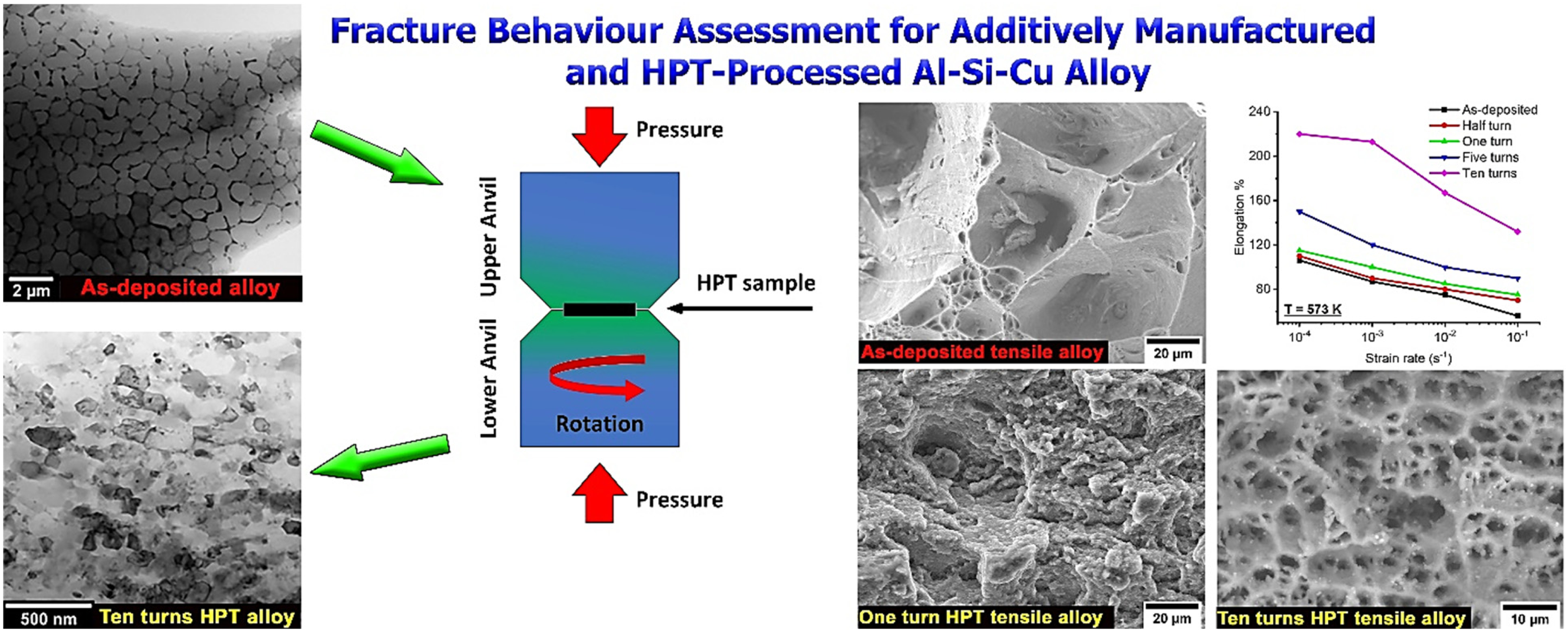
Introduction
Additive manufacturing (AM) of aluminium alloys has received significant attention recently due to their controllable microstructures and properties that could meet engineering requirements in the industry.1–3 A variety of aluminium alloys have been additively manufactured and investigated such as Al–Si–Mg4–7 and Al–Si8–11 to evaluate the property–microstructure relationships upon using additive manufacturing procedures. Al–Si–Cu cast alloy is used widely in automotive applications for engine block parts and cylinder heads,12,13 and additive manufacturing (AM) could improve the design flexibility and hence properties and performance of additively manufactured parts. 1 Laser powder bed fusion (LPBF) is considered an additive manufacturing approach that offers a potential solution for the production of 3D-printed metallic materials for various engineering applications with desirable compositions and properties, in complex geometries, where fast fabrication of required metallic parts with minimum waste in raw materials is desired over conventional casting methods.3,14 The development in the properties of LPBF additively manufactured metallic materials is attributed mainly to their unique cellular melt pool structures, the high fraction of low angle grain boundaries and dislocation density in comparison with their counterparts made via conventional casting methods. Hence the manufacturing–structure–property relationships and thus the alloy's design for additive manufacturing via LPBF can potentially be controlled to develop the required performance beyond that available via conventional metalworking operations.14,15 Currently, the industrial application of LPBF of metallic alloys includes manufacturing commercial aluminium alloys such as Al–Si–10Mg and Al–7Si–0.6Mg to be used in the aerospace industry with promising opportunities for large-scale manufacturing due to the benefits of rapid rates of additive manufacturing of parts with net-shape finishing. However, widespread LPBF additive manufacturing of metallic alloys requires high-purity atomized pre-alloyed powders and hence the need for extensive research to characterize and determine the necessary stoichiometric compositions and resultant properties for specific applications, as well as providing standardized data for such additively manufactured alloys and parts to be adopted in commercial applications.3,16,17 For instance, extreme heat exchangers, exhaust manifolds, fuel nozzle tips and inducers were additively manufactured by Boeing for aerospace applications,16,18 and cylinder heads and crankcases also were additively manufactured for transportation applications. 19 Engine brackets with high cycle fatigue performance were designed and additively manufactured by LPBF for aero-engine applications. 20 LPBF was also employed for manufacturing of shift block supports to be used in turbine blades of hovercrafts in one step without further finishing steps demonstrating the promising applicability of LPBF in these sectors of industry. 21
However, these alloys have unavoidable microstructural drawbacks due to additive manufacturing, such as high porosity, unmelted powders and coarse-grained morphology that cause poor mechanical performance at room and elevated temperatures. Optimization of additive manufacturing parameters will not significantly mitigate or remove these drawbacks due to the rapid cooling rate of additive manufacturing that causes unavoidable high porosity. Varying the cooling rate and/or laser power, for instance, will cause either low melting efficiency and thus a high fraction of unmelted powder within the materials under manufacturing or excessive spatter of the powders during manufacturing that leads to a differential stoichiometry between the original powders and final product as well as being an uneconomical process in comparison with traditional casting processes. Application of post-manufacturing processes such as heat treatments would slightly reduce the detrimental effects of these aforementioned drawbacks, but these processes are normally associated with a considerable reduction in the defect density and grain growth that leads to a significant lowering in the strength and superplastic performance at ambient and elevated temperatures respectively.1,2,22 Severe plastic deformation (SPD) processes have been introduced and utilized recently to overcome these issues, such as high-pressure torsion (HPT)4,23 and equal channel angular pressing (ECAP)2,24 to improve the microstructure and properties of different additively manufactured aluminium alloys. For instance, a significant reduction in the porosity by 94% and 96% was achieved in additively manufactured Al–Si–Mg and Al–Si–Cu alloys, at a quarter and ten turns, respectively, in HPT processing. Both aforementioned investigations revealed a substantial increase in the hardness of the HPT-processed additively manufactured alloys from 140 to 220 HV in Al–Si–Mg and from 120 to 240 HV in Al–Si–Cu alloys, respectively.4,23 The ten turns-HPT processing at room temperature of the additively manufactured Al–Si–Cu alloy resulted in a considerable increase in the tensile strength from 400 to 700 MPa. 25 ECAP processing of the additively manufactured Al–Si alloy resulted in the near disappearance of porosity after four passes of ECAP. An increase in the tensile strength from 465 to 514 MPa was observed after four passes of ECAP of an additively manufactured Al–Si alloy. 2 ECAP processing for 4 passes at a temperature of 873 K of the directed energy additively manufactured Ti–6Al–4V alloy resulted in a fine grain size of 1 µm due to dynamic recrystallization of the processed microstructures. 26 Laser shot peening as a severe plastic deformation process was utilized to enhance the mechanical properties of the surface layer in the selective laser melted additively manufactured Ti–6Al–4V alloy, leading to an increase in hardness from 324 to 420 HV, and an increase in ambient temperature tensile strength from 1004 to 1197 MPa due to the high density of dislocations and mechanical twins in the processed alloy. 27 A recent study on HPT processing of LPBF-additively manufactured Al–11Si alloy showed a good combination of strength and ductility post-processing at 523 K up to one HPT turn. The strengthening in this investigation was explained based on precipitation and grain refinement as the main mechanisms at the processing temperature, emphasizing the advantage of the SPD–AM combination. 28
The aforementioned investigations have shown that SPD processes have significantly altered the additively manufactured microstructures and subsequent properties in terms of evolution in porosity and hardness. These alterations included: transformations from a melt-pool morphology of 100 µm to ultrafine grains of 100 nm, extensive fragmentation of the agglomerated second-phase particles from 1 µm to fine well-distributed particles of 200 nm, a considerable reduction in porosity of up to 94%–97% after HPT in comparison with the original additive manufactured microstructures, and a significant accumulation of defects up to 5 × 10¹⁴ m−2 after HPT in comparison with the counterpart value in the original additive manufactured microstructures of 1 × 10¹⁴ m−2. The strength in terms of hardness in the HPT-processed additively manufactured alloys shows a considerable increase of up to 240 HV after HPT compared with the counterpart value in the original additive-manufactured alloys of 120 HV.4,23 A very recent investigation was reported by the authors on the tensile properties of the HPT-processed Al–Si–Cu additively manufactured alloy to understand the mechanical performance of the alloy after different levels of HPT processing. This study showed a substantial increase in the tensile strength from 400 to 700 MPa and elongation from 56% to 220% for the original and HPT-processed additively manufactured alloys, respectively, which reflects the induced microstructural alterations by HPT processing at room temperature on the properties of the unprocessed additively manufactured alloy. 25 The HPT processing at room temperature leads to substantially induced strain and a level of microstructural refinement in comparison with other SPD techniques.29,30
The aim of this investigation is to reveal, explain and assess the impact of the extensive microstructural evolution introduced via HPT in the LPBF-additively manufactured Al–Si–Cu aluminium alloy, on the mechanical performance and fracture behaviour in this alloy at ambient and elevated temperatures in tension. The effect of different strain rates in tension and the distribution of second phase particles on alloy flow and thermal stability in HPT-processed and unprocessed additively manufactured alloys will be considered. Such an assessment will allow optimization of the structural performance in these alloys via a combination of additive manufacturing and HPT processing at room temperature.
The hypothesis of this research is that the alteration in the melt-pool morphology and significant grain refinement in the LPBF-additively manufactured Al–Si–Cu alloy matrix and the second phase particles produced via HPT will significantly improve the mechanical strength and elongation-to-fracture. This will be achieved by eliminating the initial porosity, thus altering the distribution of the cavitation process, enhancing the thermal stability of the microstructure and developing a mechanism of fracture which maintains extensive deformation and material flow (superplasticity) at ambient and elevated temperature in tension. Comparing behaviour to that in the unprocessed alloy will assess the impact of HPT as a severe plastic deformation process on the LPBF-additively manufactured Al–Si–Cu aluminium alloy.
The novelty of the current research is introducing and exploiting a novel route combining room temperature-HPT-SPD and LPBF-additively manufactured Al–Si–Cu aluminium alloy. This will introduce effective enhancements in the mechanical performance, strengthening, microstructural stability and densification of this alloy to be used under conditions of ambient and elevated temperatures. Thus, eliminating any need for elemental additions, post-heat treatments or post-thermomechanical processing at elevated temperatures that would negatively affect the microstructure and properties via unnecessary processes of recovery, recrystallization, grain growth, precipitation and coarsening of secondary phases, leading to void coalescence and high fracture susceptibility.
To address the aim of this research, the LPBF-additively manufactured Al–Si–Cu aluminium alloy has been subjected to HPT processing at room temperature which has never been explored before to the authors’ knowledge. The resultant microstructural refinement via HPT and the associated mechanical properties have been investigated via tensile testing at ambient and elevated temperatures at different strain rates. Fractographic observations and microstructural stability under this tensile testing have been investigated and compared to its counterparts, the unprocessed LPBF-additively manufactured alloy and Al–Si–Cu aluminium alloy produced via traditional methods.
Materials and methods
LPBF-additively manufactured Al–Si–Cu aluminium alloy
LPBF-additively manufactured Al–9%Si–3%Cu aluminium alloy was used in this study. This alloy was deposited using LPBF as a rod bar with a vertical build-up orientation as shown schematically in Figure 1(a) in a nitrogen atmosphere. A Concept Laser M2 facility with 200 W of laser power was used to deposit this alloy. The alloy was fabricated layer-by-layer at a scan rate of 1000 mms−1, with a layer thickness and hatch spacing of 40 µm and 200 µm, respectively, with a bi-directional scan strategy. Energy-dispersive spectroscopy (EDS) was used to analyze the chemical composition of the as-manufactured alloy as shown in Table 1.
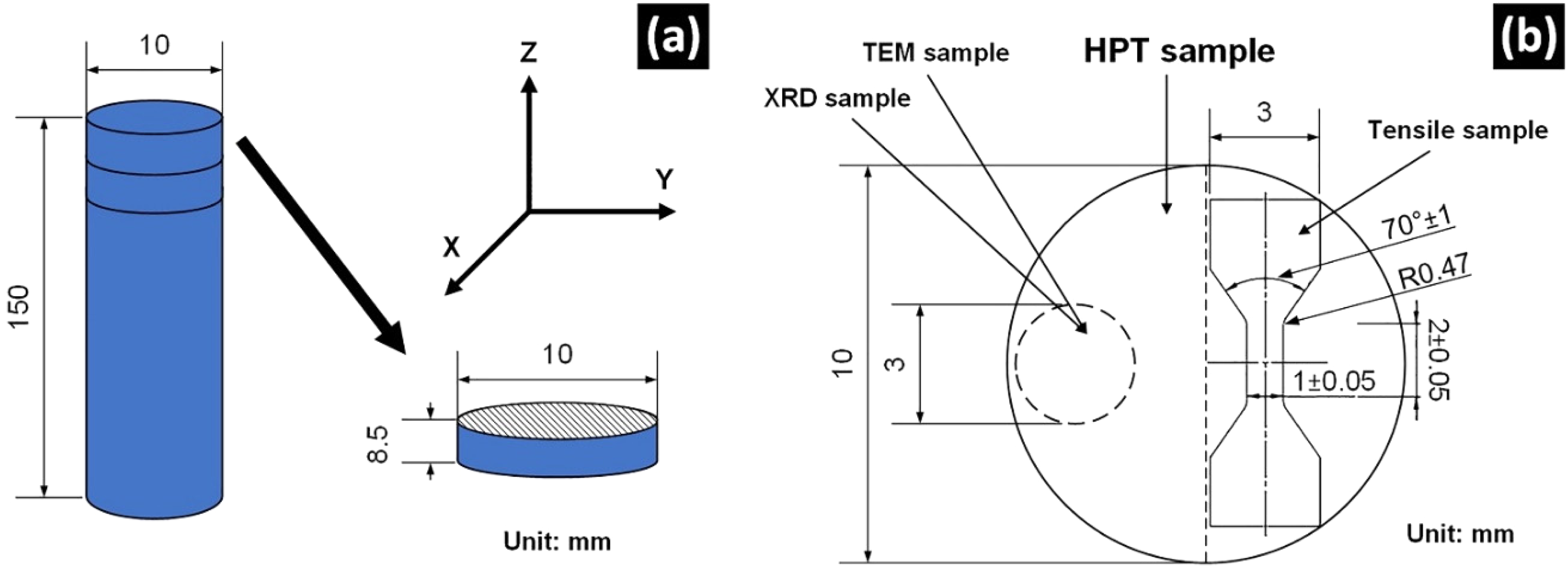
(a) Schematic illustration of the vertical Z-orientation build-up of the as-manufactured alloy bar (left) and disk-shaped sample geometry required for HPT processing (right), and (b) A drawing shows the positions of samples for the tensile, XRD and TEM investigations that were cut from the HPT disk-shaped sample.
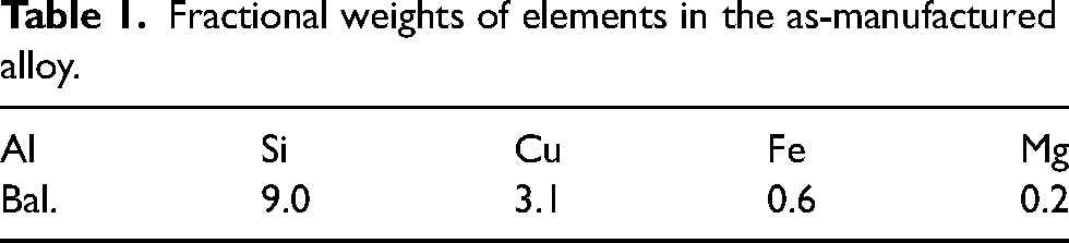
Fractional weights of elements in the as-manufactured alloy.
HPT processing at room temperature
Before high-pressure torsion (HPT) processing, the as-deposited alloy was machined into disk-shaped samples using a wire discharge machine. The dimensions of the disks were 10 mm in diameter and 0.85 mm in thickness, which are suitable to be positioned in between the anvils of the HPT machine. Room temperature-HPT processing in the quasi-constrained mode was conducted using an applied pressure of 6.0 GPa and at a speed of one revolution per minute for a different number of turns: half, one, five and ten turns. The notation of the as-deposited alloy and/or as-manufactured alloy was used in this investigation to refer to the additively manufactured alloy prior to HPT processing. The notation of unprocessed and processed alloys refers to non-deformed and deformed alloys by HPT, respectively.
Microstructural observations
The as-deposited unprocessed samples as well as HPT-processed samples were mechanically ground by SiC paper and then polished with 1 µm diamond paste. These samples were subjected to chemical etching using Keller's reagent for ten seconds. Thereafter, the samples were cleaned using ethanol and dried with compressed air. Next, the etched samples were inspected by optical microscopy (OM, Olympus BX51) and scanning electron microscopy (SEM, FEI Quanta 250) for microstructural studies. Further investigation was carried out on the as-deposited and processed microstructures using transmission electron microscopy (TEM, FEI Talos TMF200S microscope) and then analysed using an attached energy-dispersive spectroscopy unit (EDS, Oxford Instrument, High Wycombe). TEM samples were obtained in the form of miniaturized disk-shaped samples as shown in Figure 1(b). These samples were cut at the edge areas (∼ 3 mm from the edge of the HPT disk) of the HPT-processed disks with 3 mm and 100 µm in diameter and thickness, respectively, as shown in Figure 1(b). The miniaturized samples were thinned to 80 µm using abrasive paper, and then thinned to 20 µm using a high-precision pit instrument (Gatan Model 623-40 Pit Grinder). Additional ion thinning was employed at 95 K and a voltage of 5 eV at an angle of 4° using an ion beam thinning instrument (PIPS II MODEL 695). After a period of time, the voltage dropped to 1 eV when a pit appeared in the middle of the thinned TEM sample as seen by the microscope. Later, the voltage was cut and the sample was left to reach room temperature and then taken out for TEM and EDS observations. Another structural investigation on the as-deposited and HPT-processed samples was conducted through X-ray diffraction (XRD) analysis using a D2 Phaser XRD machine. The diffraction patterns were obtained from 30 to 90° using a Kα-Cu radiation source, and the Rietveld refinement method was applied for fitting. These XRD results were used to measure the crystallite size (
Mechanical testing
Tensile testing was carried out in this research to evaluate the tensile properties and fracture mechanism in the as-deposited and HPT-processed alloys. Two micro-tensile samples were cut using a wire cutting machine from the as-deposited and HPT-processed samples with dimensions of 10 × 2.0 × 0.6 mm3. The positions of the micro-tensile samples are shown schematically in Figure 1(b), where the gauge length areas of these samples are located at ∼ 1.5 mm from the central area of the HPT disks. The dimensions and cut positions of the micro-tensile samples on the HPT disks were governed by the small size of the disks, the need to extract two micro-tensile samples per HPT disk for more accurate and reliable results, and to avoid the central area of the HPT disks where microstructural heterogeneity is marked, especially for “low-turn” HPT disks. In addition to the aforementioned reasons, there was a need to extract micro-tensile samples with complete grip areas, so the samples could be held firmly in the grips of the tensile machine and to avoid any potential sliding of the micro-tensile samples within these grips which would affect negatively the accuracy and reliability of the data especially when conducting the tensile testing at elevated temperatures. Tensile tests were conducted using an MTS BIONIX tensile machine at 298 and 573 K in an air atmosphere at different strain rates starting from 10−4 to 10−1 s−1 for all micro-tensile samples obtained from the as-deposited alloy and HPT-processed alloy at a different number of HPT turns. Curves of engineering stress–strain were constructed for all as-deposited and HPT-processed samples following tensile testing at both testing temperatures. Fracture surfaces of the tested samples were also inspected using SEM and then correlated with the manufacturing, processing and tensile testing conditions. Quantitative measurements of the cavity distribution and areas were achieved over the as-tested fractured cross-sections of tensile samples in the as-deposited and HPT-processed samples.
Fractography observations
Fractured cross-sections were imaged using SEM and processed using ImageJ software where the cavities were thresholded by the grey level to allow measurement. Areas of 6000 and 600 µm2 were involved in the calculations for the as-deposited and HPT-processed samples, where the differentiation in the areas here is attributed to the larger cross-section of the fracture in the tensile samples of the as-deposited alloy in comparison with the HPT-processed alloy. These areas for all fractures were subjected to the same settings of thresholding using ImageJ software, where the cavities were indexed in the software as black and then counted, where cavities less than 1 µm2 in area were not considered in this analysis in the same manner as reported in ref. 35,36. The collected data were analysed in terms of cavity fraction and perimeter as shown later.
Results
The as-deposited microstructures of the AM Al–9%Si–3%Cu alloy prior to HPT processing and after processing for ten turns in HPT are shown in Figure 2, alongside the fractional weight of elements in the alloy as tabulated in Table 1. The unprocessed as-deposited alloy showed a melt pool morphology over the horizontal HPT disk plane, where the average widths of these structures were about 150 µm with different lengths as seen in the OM micrograph in Figure 2(a). The as-deposited unprocessed alloy showed porosities of process and gas-induced forms as marked by solid and dashed indicators respectively in Figure 2(a). HPT processing has altered the melt pool morphology as seen in the etched samples in the OM micrograph in Figure 2(b) for the HPT sample processed for ten turns. The melt pools disappeared gradually with increasing the HPT turns up to ten turns, where the morphology showed almost no pools. In addition, the eutectic phase that decorated the melt pool boundaries was re-distributed as the number of turns increased in HPT. SEM observations of the etched sample in the as-deposited alloy showed two main phases: an α-aluminium matrix with a dark appearance and a eutectic silicon phase with a white interconnected network as seen in Figure 2(c). The microstructural observations by SEM of the HPT-processed samples showed a significant alteration in the morphologies of the alloy structure. The eutectic silicon network was increasingly sheared and refined down to nano sizes as seen in Figure 2(c) and (d), and the porosities within the α-aluminium phase progressively disappeared as the HPT deformation proceeded up to ten turns. The bright and dark field views of as-deposited and ten turns HPT-processed microstructures at the edge areas of the disk-shaped samples as investigated by TEM are presented in Figure 3(a)–(d) associated with selected-area electron diffraction (SAED) patterns, alongside the representative distributions of chemical elements in these areas as shown in Figure 4. The as-deposited alloy exhibited an average grain size of 722 nm, whereas the HPT-processed alloy for ten turns showed a minimum grain size of 66 nm. The average particle sizes of silicon and copper intermetallic phases were 50 and 90 nm, respectively for the HPT alloy deformed by ten turns. The XRD crystallite size measurements showed a remarkable decrease in the XRD domains to about 30 nm as presented in Figure 3(e), associated with a considerable dislocation density of about 6.2 × 10¹⁴ m−2 for the ten turns HPT-processed alloy in comparison with its counterpart value in the as-deposited alloy of 1.1 × 10¹⁴ m−2 as shown in Figure 3(f) and (g).
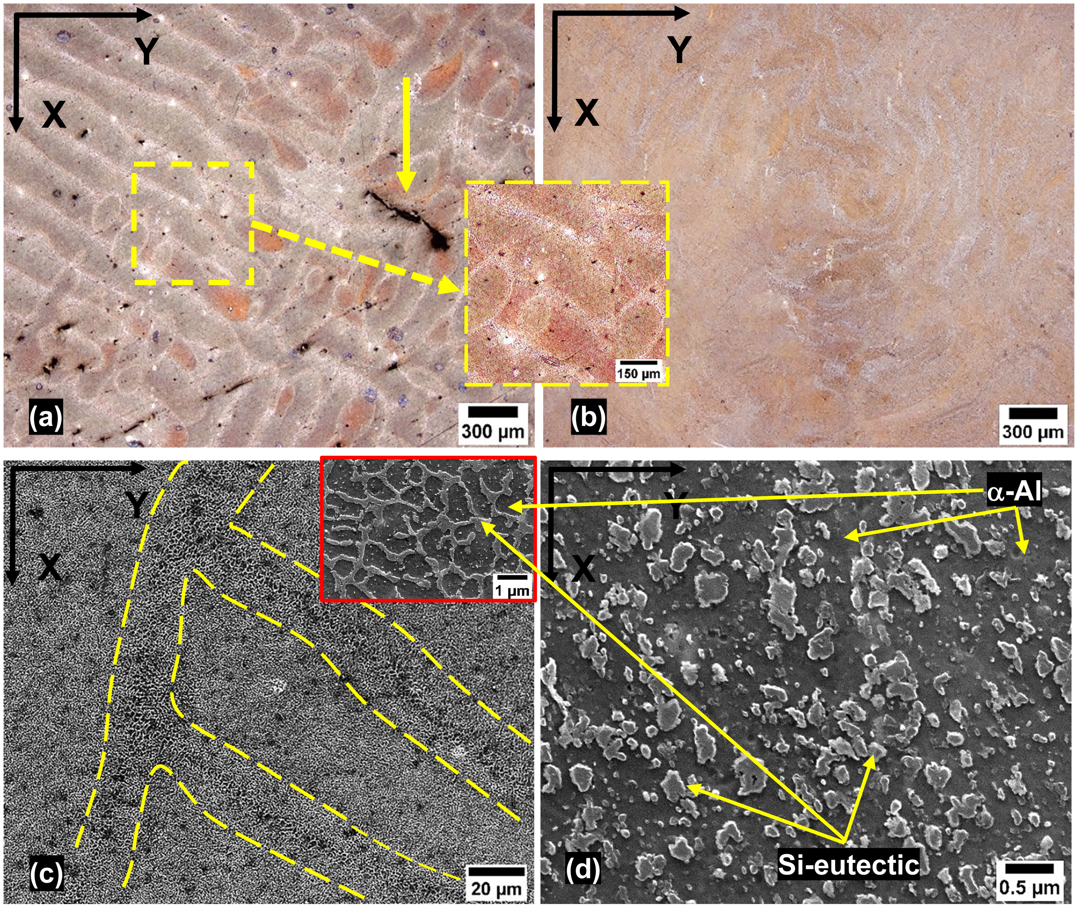
Microstructural observations of (a) as-manufactured microstructure associated with the magnified micrograph shows gas-induced porosity, whereas the solid arrow represents process-induced porosity, (b) ten turns HPT-deformed microstructure as noticed by OM, (c) melt pool boundaries in the as-manufactured microstructure associated with the magnified micrograph showing a silicon eutectic network and (d) ten turns HPT-deformed microstructure as found by SEM, where the α-aluminium matrix and silicon eutectic network and particles appear dark and white after etching, respectively.
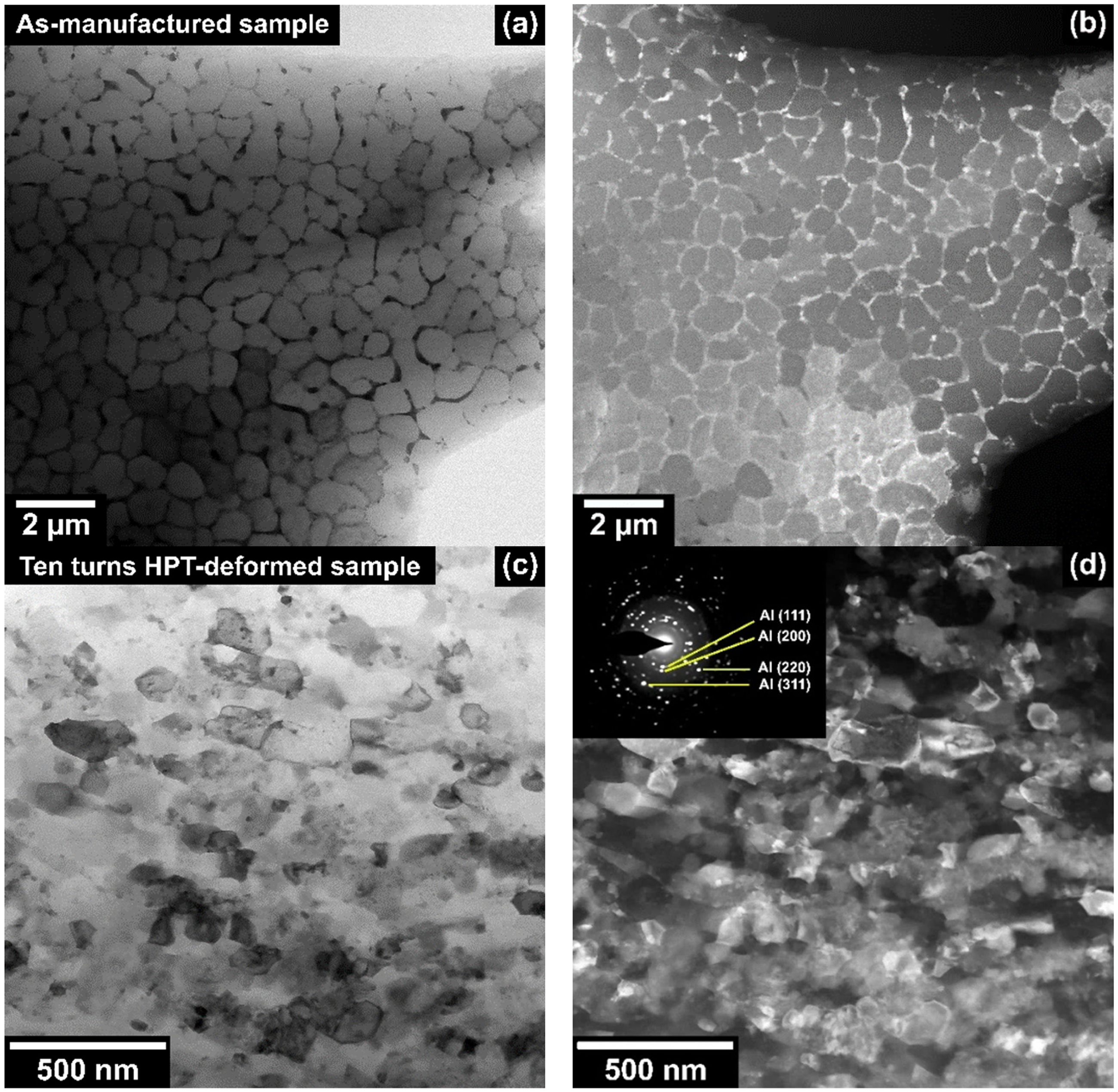
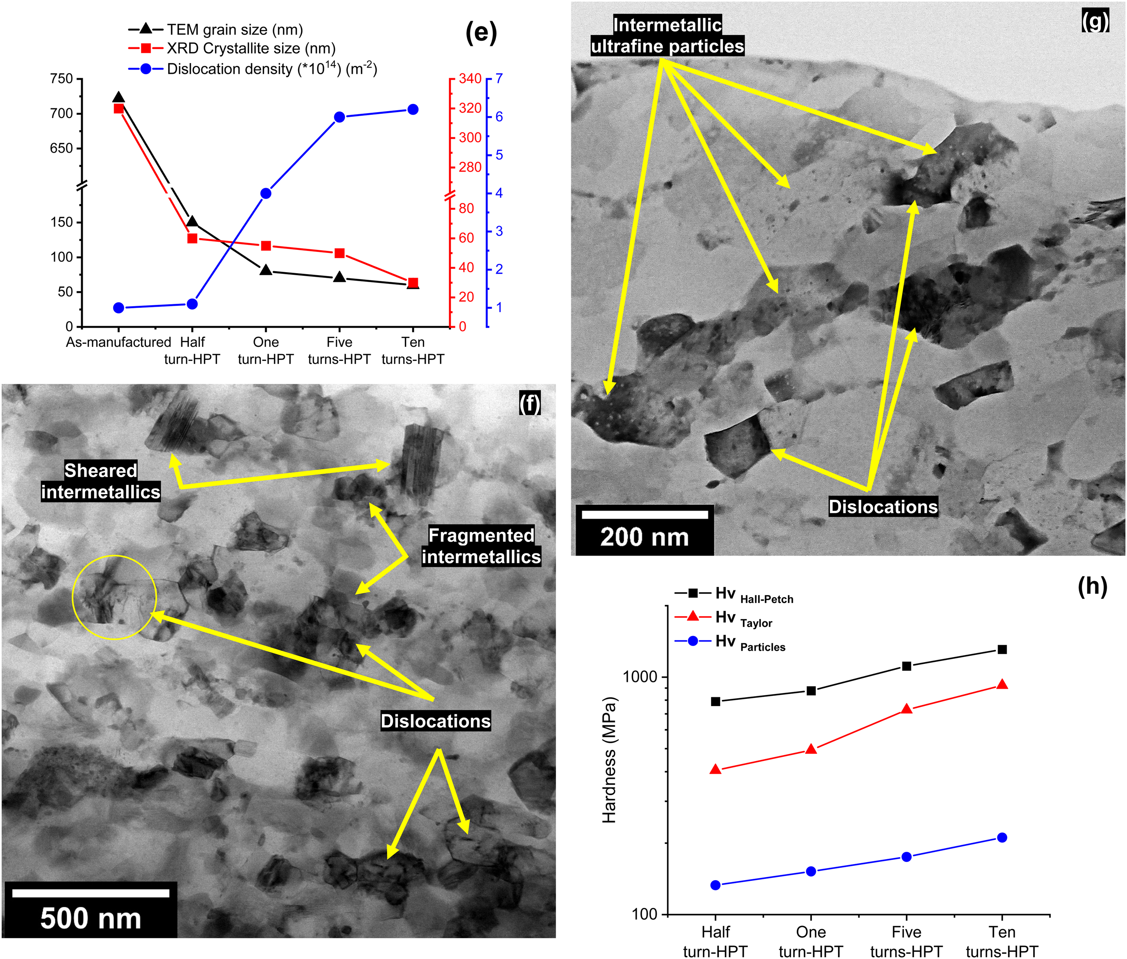
Representative bright and dark field images of TEM microstructures for (a and b) the as-manufactured sample, (c and d) ten turns-HPT deformed sample, associated with the SAED pattern, (e) the evolution in the TEM grain size, XRD crystallite size and dislocation density for the as-manufactured and HPT-deformed (for different number of HPT turns) samples, (f and g) dislocation structures associated with sheared, fragmented and ultrafine intermetallic particles in ten turns HPT-deformed sample and (h) contributions of Hall–Petch (grain refinement), Taylor (dislocation pile-ups) and nanoparticle strengthening mechanisms to the overall strength in the HPT-deformed additively manufactured Al–Si–Cu alloy.
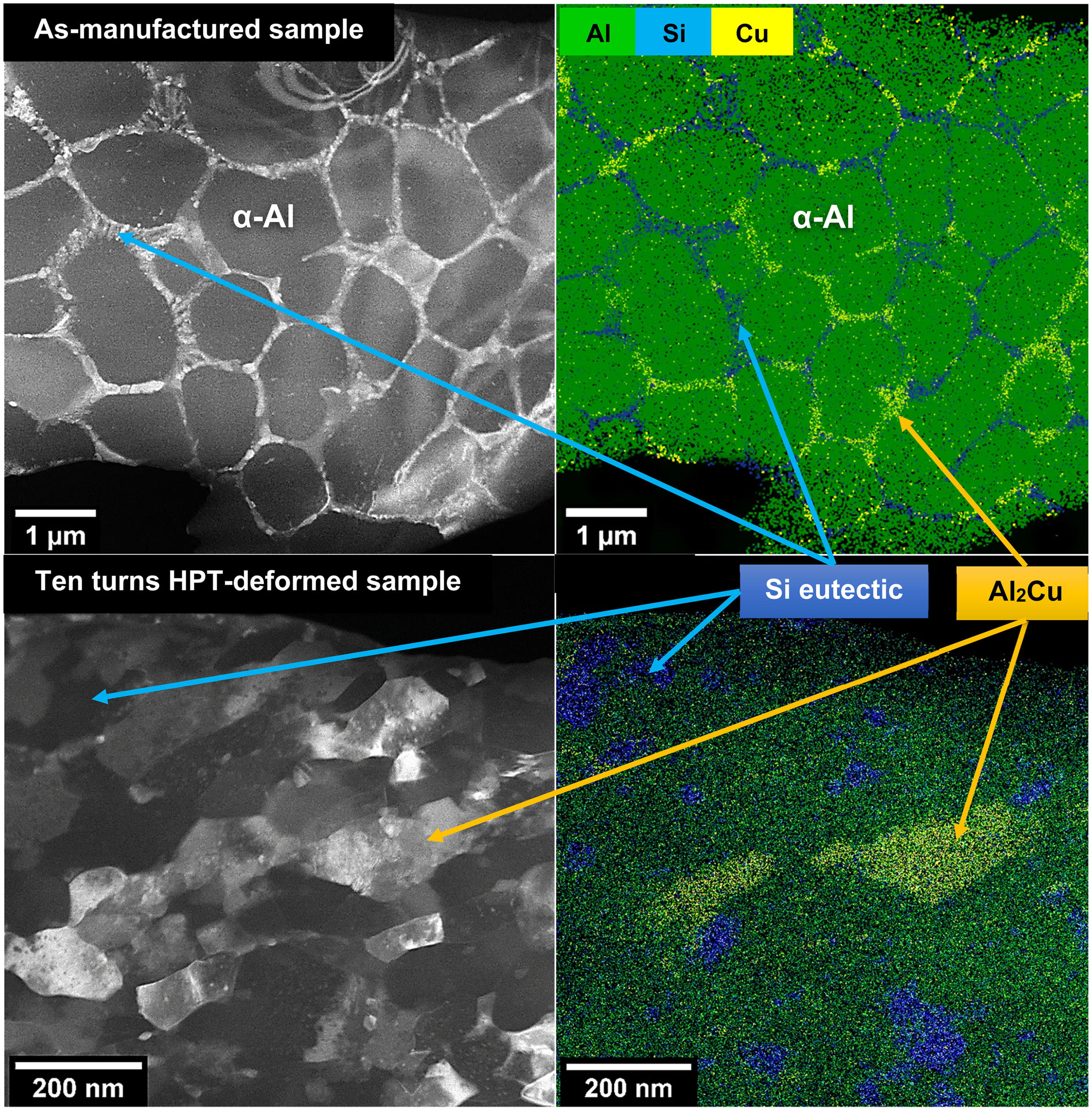
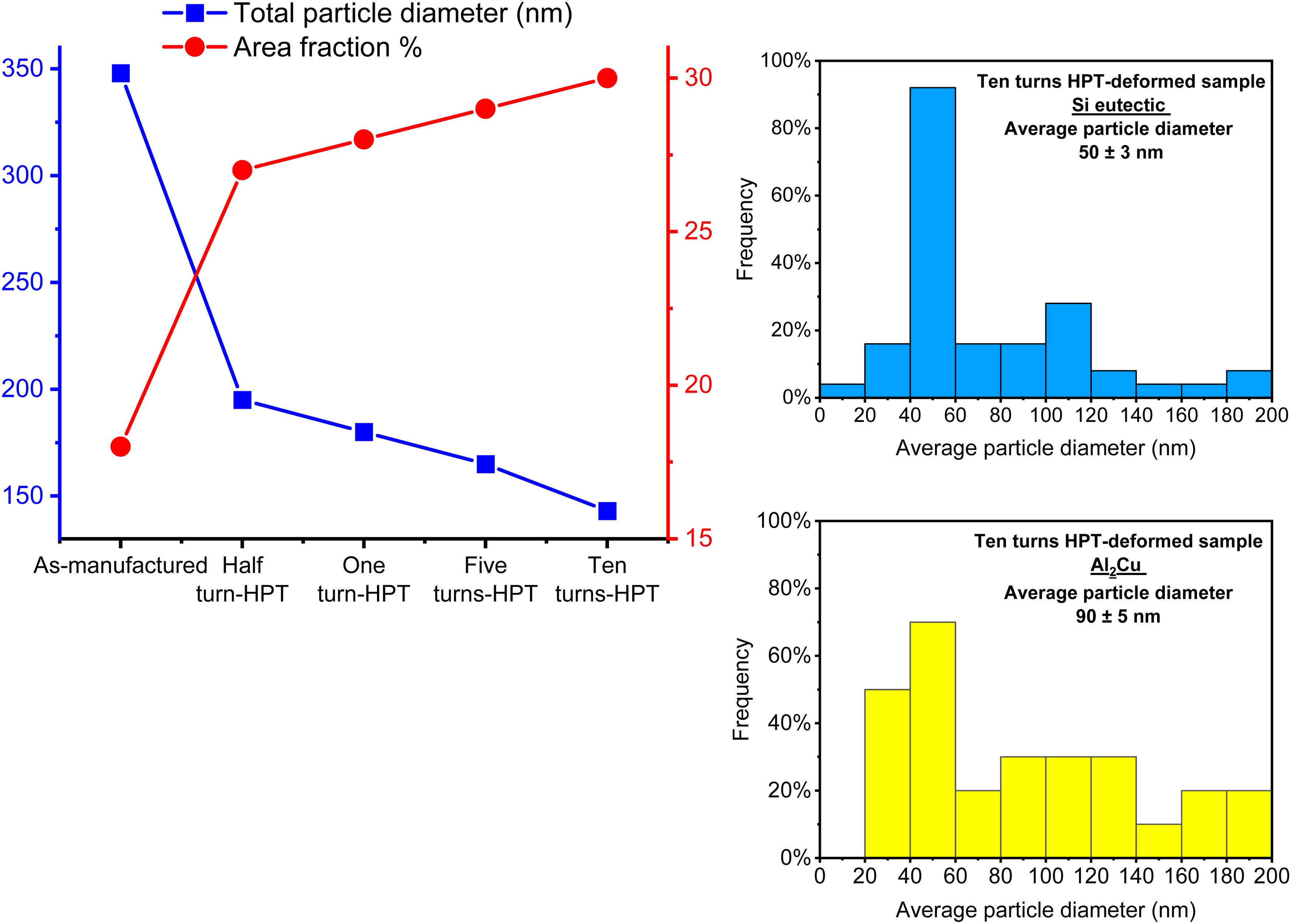
Representative maps of TEM-EDS spectra for the as-manufactured sample (top row) and ten turns-HPT deformed sample (middle row), showing the main constituents in the alloy under investigation; aluminium (α-Al), silicon (in the form of Si eutectic) and copper (in the form of Al2Cu), associated with the total particle diameter (obtained from SEM micrographs in Figure 2) for both intermetallic phase particles of Si eutectic and Al2Cu and the distribution of each phase (bottom row).
The mechanical behaviour of the additively manufactured Al–Si–Cu alloy is obtained using the engineering stress–strain plots in Figure 5, for the as-deposited and HPT-processed samples for ten turns, respectively. These samples were tested by tensile testing at ambient temperature (298 K) and at elevated temperature (573 K) which corresponds to 0.65
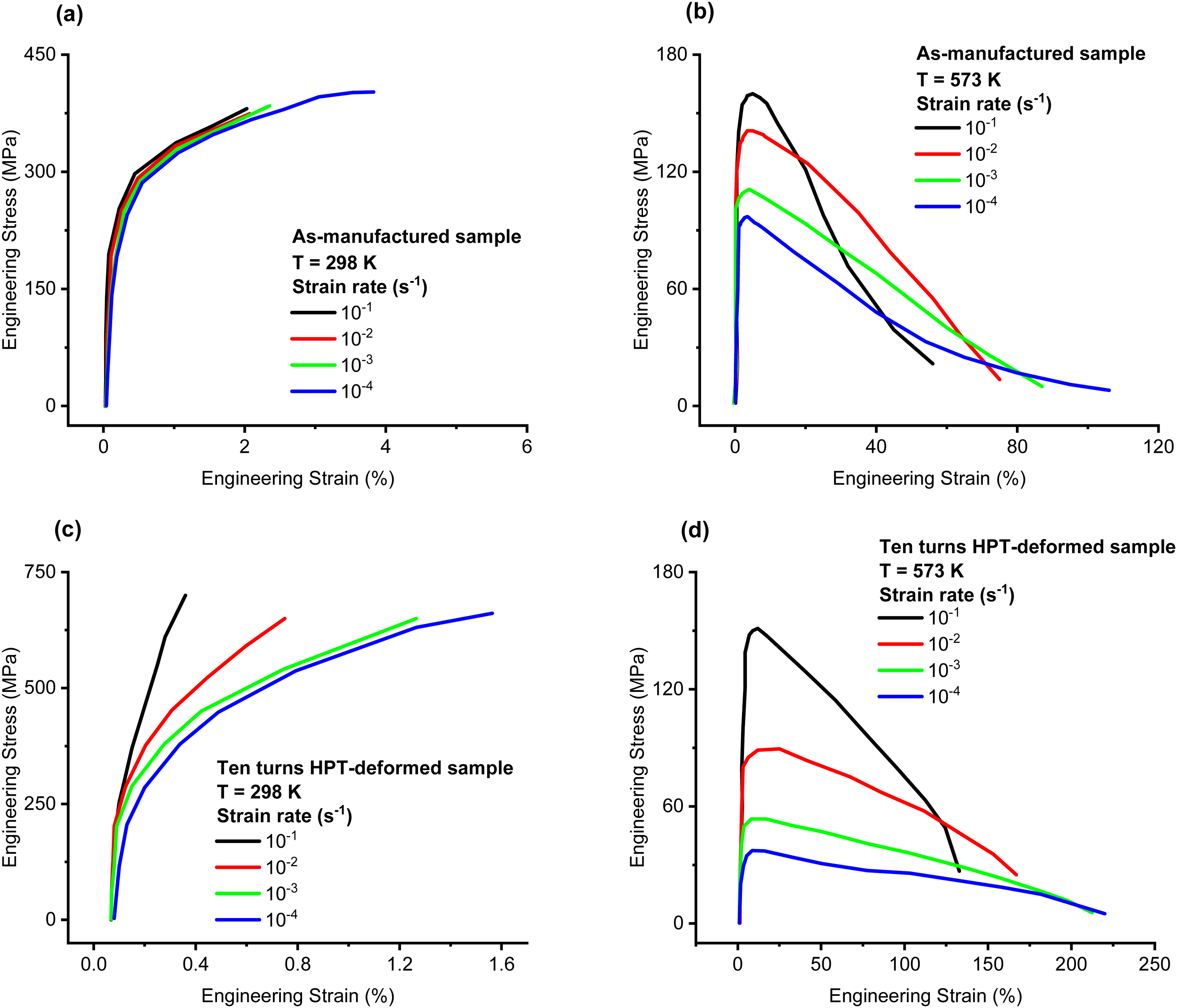
The mechanical behaviour of the (a and b) as-manufactured samples and (c and d) ten turns HPT-deformed samples during the tensile test at 298 and 573 K using different strain rates.
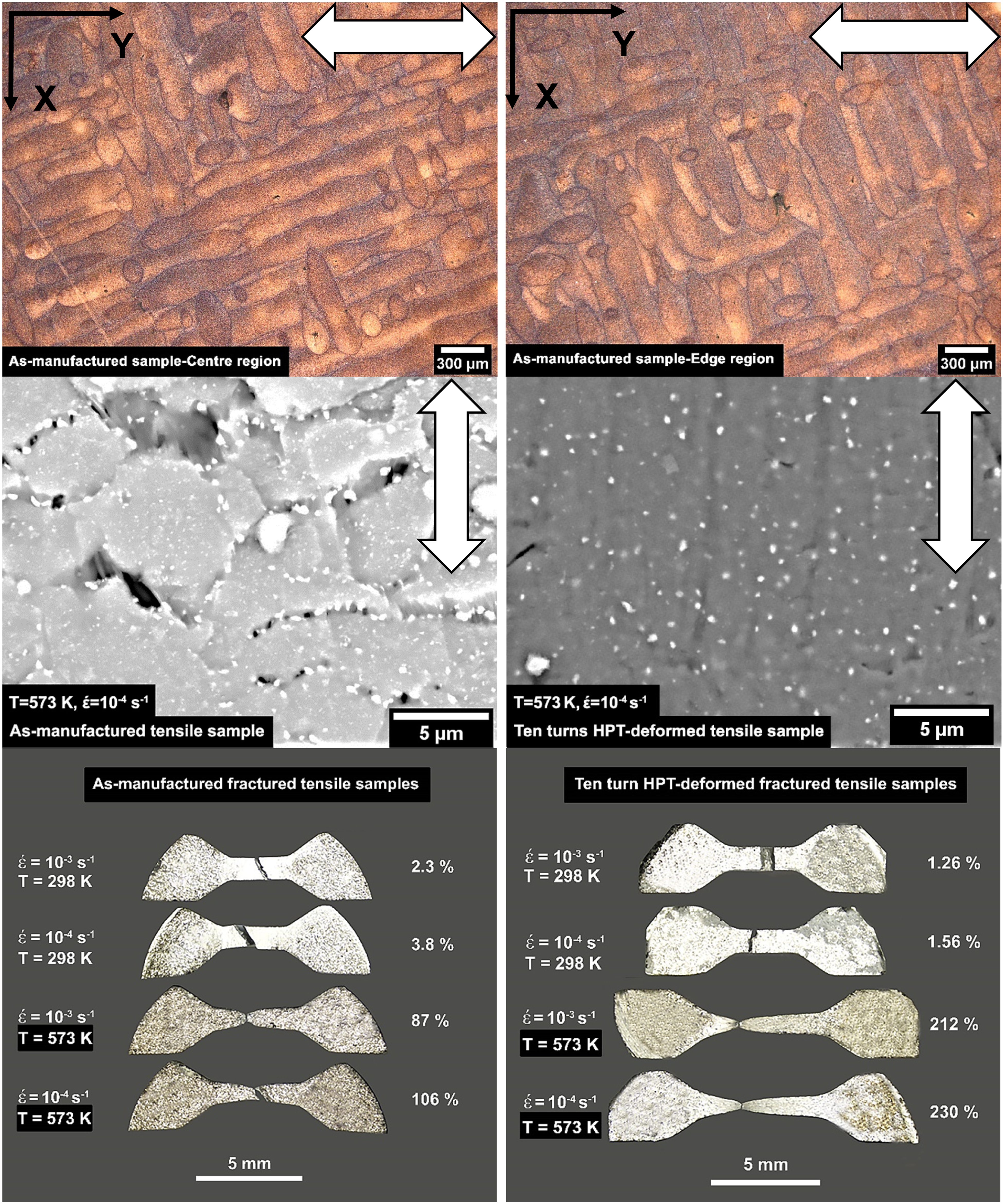
Top row: representation of the tensile loading direction (as labelled by arrows) regarding the melt pool orientation in the as-manufactured samples, middle row: microstructural surface morphology on the gauge lengths of the as-manufactured and ten turns HPT-deformed tensile samples and bottom row: fractured tensile samples corresponding to the as-manufactured and ten turns HPT-deformed samples during the tensile test using different tensile strain rates at 298 K and 573 K.
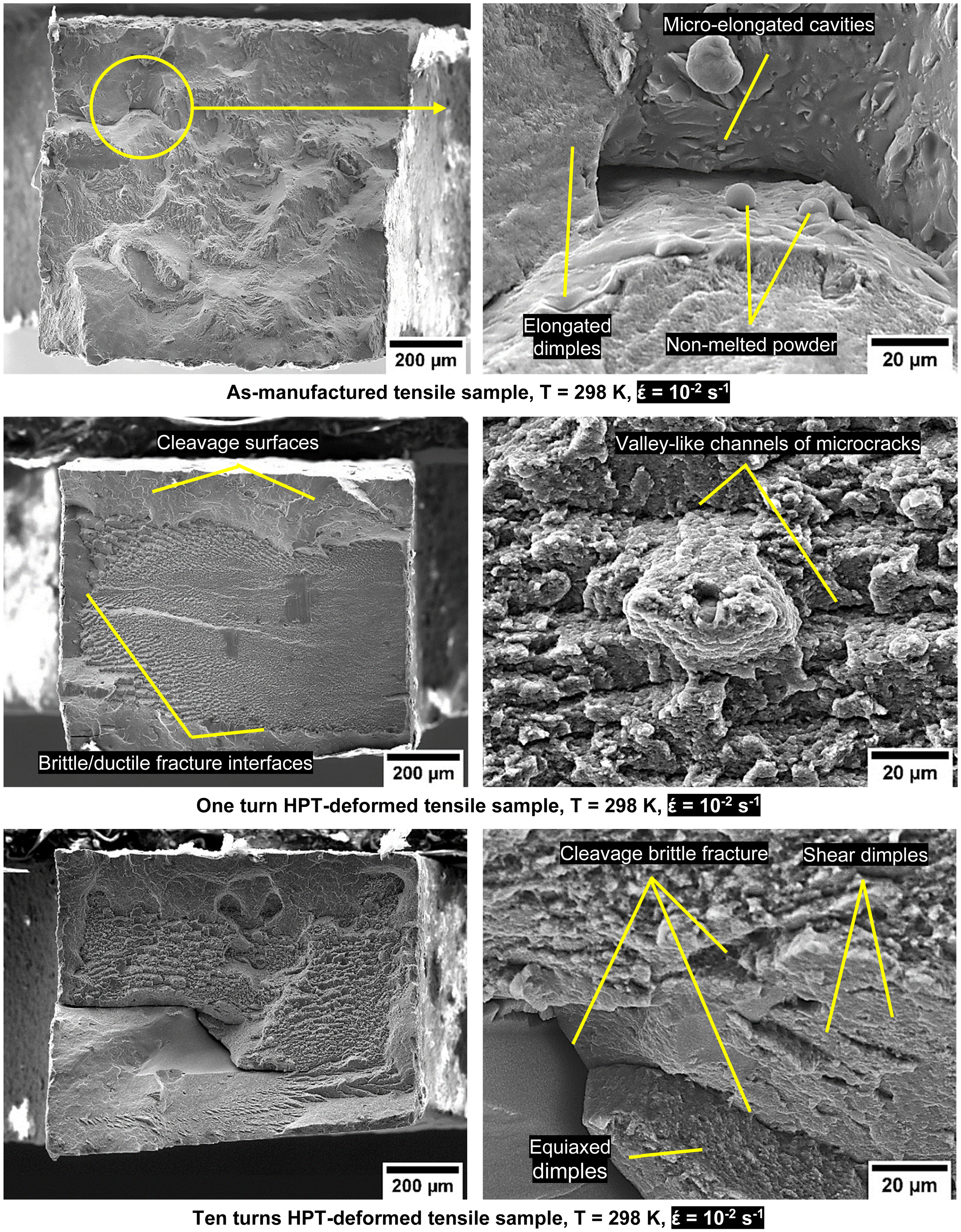
SEM observations of the fractured cross-sections for the tensile samples of the as-manufactured, one turn and ten turns HPT-deformed samples tested at 298 K using strain rates of 10−2 and 10−4 s−1.
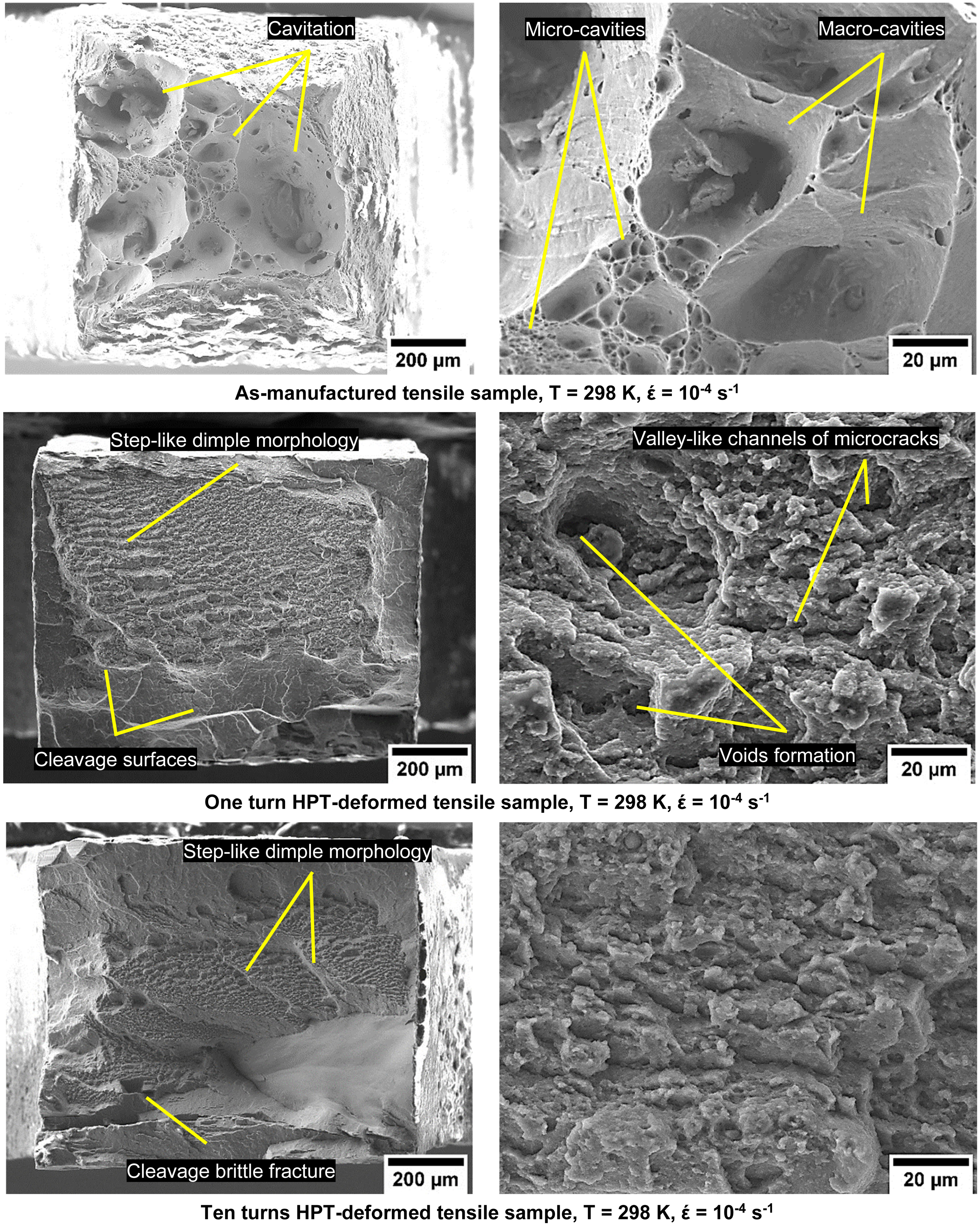
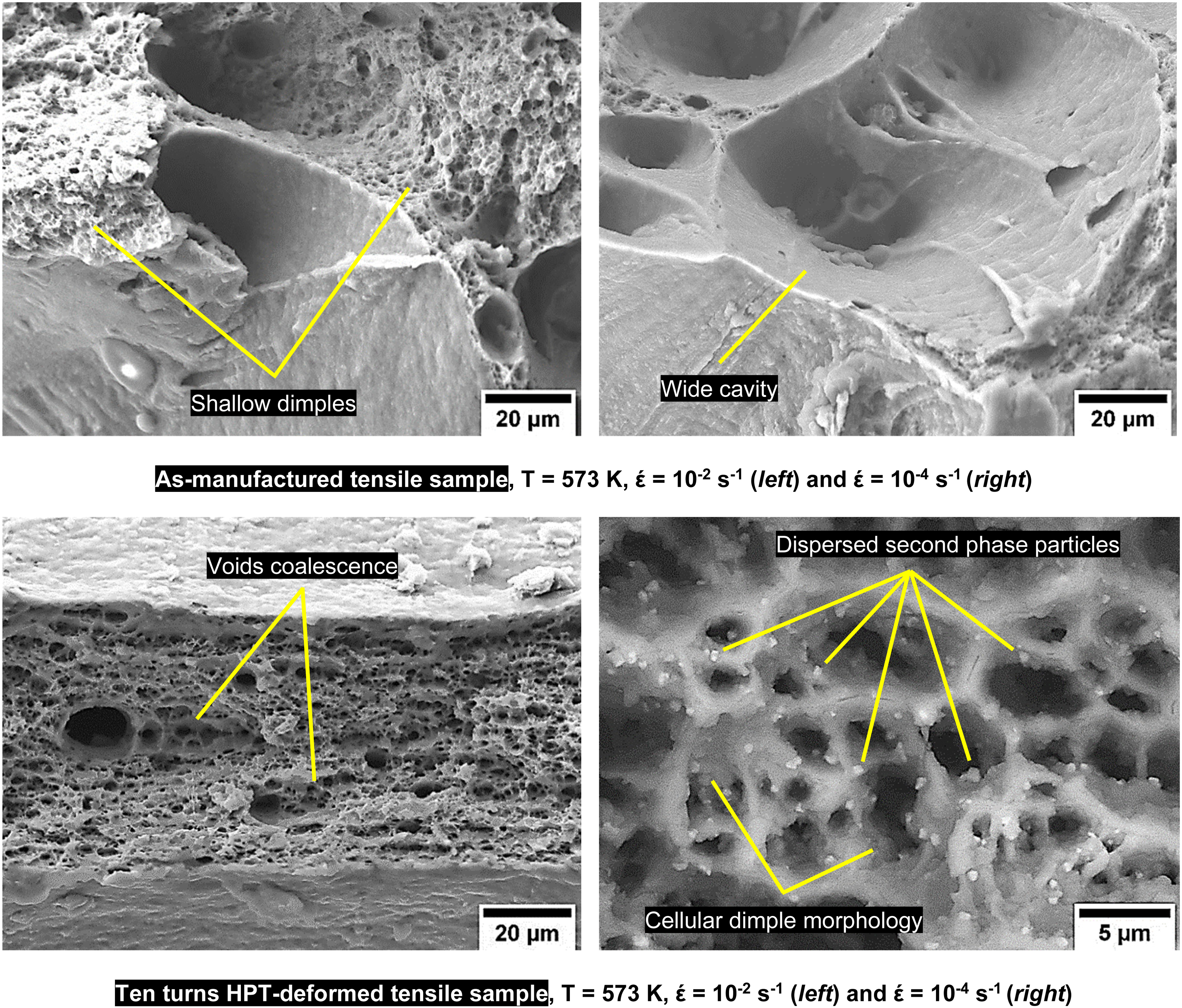
SEM observations of the fractured cross-sections for the as-manufactured and ten turns HPT-deformed tensile samples tested at 573 K using strain rates of 10−2 s−1 and 10−4 s−1.
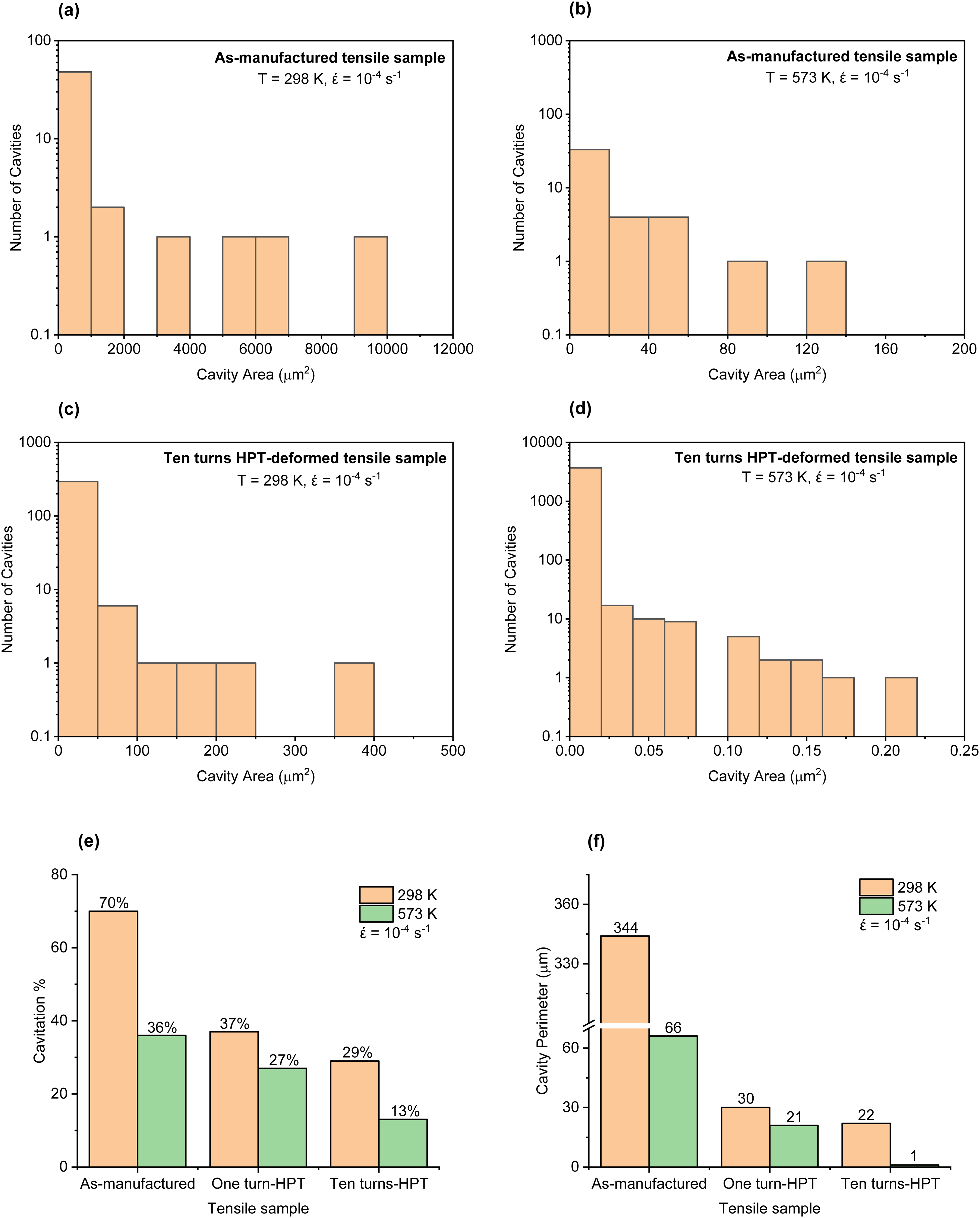
(a–d) distribution of cavities versus cavity area after tension at 298 and 573 K using a strain rate of 10−4 s−1 for the as-manufactured and ten turns HPT-deformed tensile samples. The comparisons in (e) fractions of cavitation and (f) cavity perimeters for the samples above.
Discussion
Structural evolution
The initial as-deposited alloy showed a melt pool grain morphology with irregular configurations as seen by OM in Figure 2(a) and (b), this is attributed to the partial overlapping of adjacent melt pools during the LPBF process.1,37 Development of a microstructure consisting of a fine dendritic cellular morphology (consisting of relatively fine grains) with a size of 0.5 µm inside the melt pools as indicated by dashed lines in Figure 2(c) rather than a relatively coarse dendritic cellular morphology (consisting of relatively coarser grains in comparison with counterparts in fine dendritic cellular morphology) of 2 µm is attributed to the high values of cooling rates that are associated with the LPBF process. The coarse microstructure that appears inside the melt pool boundaries arises as a consequence of the heat-affected zone that formed around the incident laser beam, where the as-deposited material is subjected to annealing due to the thermal gradient from the centre of the melt pool towards its edges.1,37 The as-deposited alloy showed a mean grain size of 722 nm whereas the processed as-deposited alloy was significantly refined when using HPT down to a grain size of 66 nm for the alloy processed for ten turns, as observed by TEM as presented in Figure 3 (a)–(e). The absence of dynamic recovery and recrystallization during HPT at room temperature has resulted in this significant grain refinement and subsequent mechanical behaviour.38–40 The measured TEM grain size was consistent with the calculated XRD crystallite size (normally the TEM grain size after SPD processing is 2∼4 times that of the XRD crystallite size), where both data were inversely proportional to the additional HPT deformation that has resulted in considerable dislocation accumulation.38,34,41 Referring to values of grain sizes and dislocation density in the as-deposited and HPT- processed alloys, shows the influence of the HPT at room temperature in introducing a heavy deformation that improves the hardening of the AM alloy at ambient temperature and the flow behaviour at elevated temperature. Despite the high value of dislocation density in the as-deposited alloy, the HPT-processed alloy gained several orders of magnitude of this density by additional generation and multiplication of dislocations, which reflects a significant increase in the strength of the HPT-processed alloy in comparison with the as-deposited alloy as indicated by hardness measurements.23,29,42,43 The inevitable defects in AM alloys such as porosity are considered as sources of premature failure in engineering applications. Thus, a successful combination of high-pressure torsion with AM has resulted in the elimination of these drawbacks and alteration in the microstructure and properties of these alloys thus achieving improved performance.1,4 The effect of HPT processing on porosity evolution in the current additively manufactured alloy was investigated, discussed and reported in detail in an earlier study. 23 In the current investigation, the HPT has introduced a remarkable alteration in the melt pool morphology of the as-deposited AM alloy from the elongated-pool microstructure to an ultrafine-grained microstructure. These microstructural changes were obvious in the formation of nanosized grains as seen by the TEM observation in Figure 3(c) and (d), and the formation of nanosized eutectic particles as seen by SEM observation in Figure 2(d) and TEM-EDS observations in Figure 4. The heavy torsional and compressive strains in HPT have a significant impact on extensive structural refinement in the HPT-processed AM alloy.44,45 The measurements of the TEM grain size as presented in Figure 3(e) indicate the occurrence and progression of considerable microstructural refinement post-HPT starting from half turn up to ten turns compared to the as-deposited alloy. The fraction of fine grains increased with an increase in the number of HPT turns. The ultrafine microstructures have occurred at an early stage of HPT deformation; i.e., after only one turn-HPT, as measured and presented in Figure 3(e) indicates the high level of the imposed HPT deformation strain within the processed alloy at this stage. The SAED patterns by TEM investigation of the ten turns HPT-processed sample showed many separated spots as seen in Figure 3(d) indicating the development of a large fraction of high-angle boundaries as the deformation proceeds by increasing the HPT straining and these spots correspond to individual grains within the selected area.29,46,47 The diffraction rings obtained by SAED patterns all belonged to aluminium with different crystal planes that matched with XRD diffraction patterns. 23
A comparison between the as-deposited and HPT-processed alloys regarding their representative distributions of alloying elements as presented in Figure 4 reveals that the eutectic silicon phase alongside the copper content (in the form of Al2Cu) was preferentially located at the cellular boundaries in the as-deposited alloy. This was also seen in terms of the white-appearance network revealed by SEM observations and labelled in Figure 2(c) and (d) and TEM-EDS observations in Figure 4. However, the HPT-processed alloy exhibited a considerable alteration in the morphology and distribution of the aforementioned constituents within the aluminium matrix due to the HPT deformation. These phases were redistributed significantly as seen from the SEM image in Figure 2(d) and TEM-EDS observations in Figure 4, where the dendritic network has vanished gradually with progressing HPT deformation. The fragmentation and re-distribution of the coarse dendritic network into fine particles were attributed to the combination of compressive and torsional strains during the HPT process that works effectively in the microstructural refinement process as shown in Figure 3(f) and (g) and Figure 4 where nanosized intermetallic phases were formed by shearing deformation that was imposed during HPT processing.23,29 Therefore, the large imposed strains by HPT have resulted in extensive particle fragmentation associated with a high-volume fraction of nanosized particles of the intermetallic phases as observed by representative distributions of chemical elements in Figure 4. The presence of these nanosized particles would influence the microstructural refinement via the formation of localized stress regions that are induced around these particles, where fine silicon particles were found to act as sites for dislocation multiplication during severe plastic deformation as shown in Figure 3(f) and (g). The multiplication and re-arrangement of dislocations forming new grain boundaries and then ultrafine grains during the severe plastic deformation of the Al–Si alloys was encouraged by the higher silicon content in the aluminium-silicon alloys. Additionally, the fine silicon particles may also undergo strain-induced dissolution within the alloy matrix under the condition of large imposed HPT strains.48–51 Therefore, the existence of relatively homogenous fine intermetallic particles within the alloy matrix hinders dislocation motion and grain growth at ambient and elevated temperatures, respectively, resulting in the improvement of the ambient temperature strength and superplastic behaviour at elevated temperatures.25,52 These outcomes were supported by the current findings of highly-dispersed intermetallic nanosized particles, extensive grain refinement and considerable dislocation density in the severely plastic deformed Al–Si–Cu alloy in comparison with their additively manufactured and conventional counterparts.
Mechanical behaviour
The HPT-processed samples exhibited higher strain hardening during room temperature-tensile testing compared to the as-deposited samples. A comparison between the ten turns HPT-processed sample with the highest strain hardening observed in this investigation with the as-deposited sample is shown in Figure 5(a) and (c). The HPT-processed samples showed lower strain hardening at elevated temperature tensile testing compared to the as-deposited samples, particularly at lower strain rates and a higher number of HPT turns. This may be ascribed to the increase in hardening of the HPT-processed samples with an increase in HPT turns.44,45,53 A significant dislocation density was introduced in the room temperature-HPT-processed samples,54,55 leading to a high level of strengthening that gave higher tensile strengths in all HPT-processed samples during tension testing at a temperature of 298 K at all strain rates as shown in Figure 5(c). Furthermore, the enhancement in tensile strength for the HPT-processed alloy is attributed to the presence of uniformly distributed nanosized eutectic particles compared to the as-deposited alloy. This phase was fragmented proportionally as the HPT turns increased and settled within the alloy matrix, which resulted in a uniform distribution at high HPT turns as shown in the SEM image in Figure 2(d) and TEM-EDS images in Figure 4. Therefore, the accumulation of dislocations around these well-distributed nanosized particles within the alloy matrix would increase the tensile strength in the tensile samples during testing at ambient temperature,56,57 as shown for the HPT-processed samples in Figure 5(c) compared to the as-deposited sample in Figure 5(a). In the current investigation, the as-deposited and HPT-processed additively manufactured Al–9%Si–3%Cu alloys have shown higher values of tensile strength of 400 and 700 MPa during tensile testing at room temperature, respectively, in comparison to their counterpart values in earlier studies of 250 MPa in the ECAP-processed Al–11%Si alloy, 58 124 MPa in the ECAP-processed Al–10%Si alloy, 59 and 250 MPa in ECAP-processed Al–7%Si alloy. 60 These findings confirm the higher impact of room temperature-HPT over elevated temperature-ECAP due to the finer grains and second phase particles that formed during room temperature processing rather than in elevated temperature processing.29,30,56 The manufacturing orientation has added a contribution to the tensile strength of the as-deposited alloy in this investigation. The alloy rod was deposited along the Z-direction and then HPT disk samples were cut parallel to the X–Y plane as shown schematically in Figure 1(a). The micro-tensile samples, as shown in Figure 1(b) and Figure 6, were cut somewhat in parallel to elongated melt pool structures that lie within the X–Y plane. This continuity of the deformation was sustained during tension by virtue of the alignment of the tension loading direction with melt pools, and cross-linking of different oriented pools has resulted in an improvement in the hardening of the as-deposited state.61,62
Improved elongations were achieved in the HPT-processed samples compared to the as-deposited samples when tested in tension at elevated temperature rather than at ambient temperature as presented in Figure 6. At a temperature of 573 K and a strain rate of 10−4 s−1, the HPT-processed samples showed a maximum elongation of 220%. This is the largest elongation that has been achieved in the HPT-processed additively manufactured Al–9%Si–3%Cu alloy to the authors’ knowledge. The tensile elongations and strength of the current AM alloy were significantly higher than earlier reported data for the Al–Si–Cu alloy.58,63,64 The elongation to failure for the ten turns HPT-processed AM Al–9%Si–3%Cu alloy was also higher than that seen for the ECAP-processed Al–11%Si alloy which showed an elongation of 34% at a temperature of 573 K using a strain rate of 2.3 × 10⁻³ s−1,
58
with a tensile strength of 250 MPa at a testing temperature of 423 K. The HPT-processed AM alloy elongations were also higher than ECAP-processed Al–7%Si alloy that was processed at temperatures of 473–573 K, which resulted in an elongation of 28% and a tensile strength of 350 MPa.
60
The present elongation of the ten turns HPT-processed AM alloy was also larger than that of the ECAP-processed Al–11%Si alloy, which showed an elongation of 150% at a temperature of 788 K and using a strain rate of 5 × 10⁻⁴ s−1.
45
The SPD of Al–Si alloys has produced effective ultrafine microstructures at room temperature rather than at elevated temperatures.45,51 Thus, improved tensile elongations are anticipated during hot tensile deformation due to the operation of superplastic flow in the presence of fine equiaxed grains.43,65 In the current investigation, an ultrafine-grained microstructure of the AM Al–9%Si–3%Cu alloy with a grain size of 66 nm was obtained by HPT at room temperature, which resulted in improved strength and elongations at temperatures of 298 and 573 K in the tensile test, respectively. Increasing the severity of HPT deformation via a higher number of turns (up to ten turns) has resulted in improvement in both ambient temperature-tensile strength and elevated temperature-tensile elongation as shown in Figure 6. The hardness and tensile strength in the room temperature-HPT-processed additively manufactured alloy were much higher than in its elevated temperature-HPT-processed and unprocessed counterparts. This can be attributed to the occurrence of strengthening mechanisms due to grain refinement and dislocation pile-ups and nanoparticles, which can be estimated via Hall–Petch, Taylor and Orowan relationships, respectively. In the current investigation, the strengthening which has arisen via obstruction of dislocations by grain boundaries, i.e., grain refinement strengthening, was relatively higher than in its counterpart which has arisen via dislocation–dislocation interactions at the grain boundaries, i.e., dislocation strengthening and dislocation obstruction and pinning by nanosized particles, i.e., nanosized particle strengthening.41,55 Hall–Petch strengthening was calculated based on the TEM grain size and hardness data using the relationship:
Tensile fractography
The present HPT-processed AM Al–9%Si–3%Cu alloy has shown remarkable plasticity and microstructural thermostability where the average grain sizes were 10 and 5 μm in the as-deposited and ten turns HPT-processed tensile samples after tensile testing at 573 K at a strain rate of 10−4 s−1 as shown in Figure 6, in comparison with earlier reports of ECAP-deformed Al–Si alloys.58,60,64 The thermal stability in microstructures of the HPT-processed additively manufactured alloy was greater than in the as-deposited alloy under the same testing conditions of temperature and strain rate. This stability was assisted greatly by the ultrafine grains and high-volume fraction of well-distributed nanosized second phase particles in the initial stage of the hot deformation in tension when compared to the unprocessed additively manufactured alloy. HPT processing has altered the melt-pool grain structure of different sizes and shapes into an ultrafine grain structure with relatively homogeneous equiaxed shapes. Therefore, this has effectively sustained deformation uniformity and improved the stability of the microstructures in the HPT-processed samples in the initial stages of the hot flow of the samples in tension. These fine structures were found to suppress any rapid grain growth during hot deformation.43,73 The nanosized-phase particles have a relatively lower melting point of 833 K in comparison with the melting point of the alloy at 873 K, 12 and a high volume fraction of nanosized particles resulted from HPT deformation. It is highly likely that these particles have aided the gliding of ultrafine grains over each other supporting grain boundary sliding in the HPT-processed additively manufactured alloy tested in tension at a temperature of 573 K. This resulted in achieved elongations that were considerably higher in the HPT-processed additively manufactured alloy in comparison with as-deposited alloy where a significantly lower volume fraction of the second phase particles were distributed along melt pools in the form of coarse particles.74,75
The extensive distribution of nanoscale eutectic particles in the HPT-processed alloy, as seen in Figure 2(d) and Figures 3 and 4, has assisted grain-boundary sliding,43,73 whereas for the as-deposited alloy, the coarse brittle clusters of the eutectic phase have worked as crack initiation sites leading to premature cavitation failure.1,9,76 The presence of equiaxed fine grains, as seen in Figure 3(c) and (d), is essential for originating grain-boundary sliding and thus the plastic flow of the material under hot deformation conditions will dominate.65,77 The as-deposited samples illustrate mixed brittle and ductile fracture surfaces when tested in tension at a temperature of 298 K using strain rates of 10−2 and 10−4 s−1 as shown in Figure 7. The brittle fracture surfaces were rugged and associated with planes of cleavage that contained extensive micro-elongated cavities and spherical un-melted matrix powders. Ductile fracture surfaces experienced a shear stress state as confirmed by the elongated dimples. These mixed fracture surfaces were consistent with the moderate ductility that was achieved for the as-deposited samples under the test circumstances.9,78 The HPT-processed samples that were tested in tension at a temperature of 298 K and at strain rates of 10−2 and 10−4 s−1 show more cleavage surfaces associated with a dimple morphology surrounded by valley-like channels of microcracks. Lower values of ductility were achieved here due to the initiation of macrocracks at the interface of brittle/ductile fracture surfaces in HPT-processed samples at a higher number of HPT turns. 79 This is attributed to the high strength of the fine grains in the HPT microstructure so their grain boundaries lead to microcracks appearing at the grain boundaries rather than within the grains. Additionally, the nanosized eutectic particles that are distributed around the grain boundaries would act as localized shear sites resulting in decohesion of these embedded particles from the alloy matrix under tension leaving cavitation sites, which can initiate microcracks. Crack propagation until final fracture then occurred by cavity coalescence through the valley-like channels of microcracks.80,81 However, the tendency of crack formation at second-phase particles is affected by their sizes, where the critical stress that is required for crack nucleation is inversely proportional to the particle size. The crack nucleation is relatively slowed down by the particle refinement of the eutectic phase in the HPT-processed alloy when compared to the coarse particles in the as-deposited alloy. 82
The HPT-processed samples showed a step-like dimple morphology with a equiaxed dimple morphology in the fracture sections and experienced two states of fracture stresses: the uniaxial tension stress that resulted in relatively equiaxed dimple morphology leading to a tensile ductile fracture, and the shear stress that resulted in ridged fracture surfaces with elongated cavities or shear dimples leading to a shear ductile fracture.83–85 Normally, shear dimples would appear as parabolic depressions over fracture surfaces due to localized heterogeneous plastic deformation, while the equiaxed dimples occur because of homogeneous plastic deformation.86,87 The failure process started by slip under uniaxial tension in the centre of the fracture cross-section in the HPT-processed tensile samples and then ended by rupture under shear stress at the edge of the fracture cross-section.79,88 As a result, the failure crack in these samples has been generated at the dimple/ridge interface leading to a cleavage brittle fracture area that lies in-between equiaxed and shear dimpled areas.84,89 In general, severe plastically deformed metallic materials are characterized by dimpled fracture surfaces as seen in their counterparts: the coarse-grained conventional materials, but the aforementioned materials show poor ductility compared to their coarse-grained conventional counterparts. This can be attributed to their high strength combined with plasticity gained through grain refinement, which is consistent with the dimple morphology observations in the current HPT-processed and as-deposited Al–9%Si–3%Cu alloys.90,91 The size of the fracture dimples was relatively smaller in the HPT-processed tensile samples than in the as-deposited tensile samples subjected to tension at a temperature of 298 K. Moreover, this size was also finer in the samples processed at higher HPT turns. The average sizes of dimples in the as-deposited and HPT-processed tensile samples tested in tension at a temperature of 298 K were 1 and 0.5 µm, respectively, which correspond proportionally to the coarse and fine particle sizes of eutectic phase particles in the as-deposited and HPT-processed samples, respectively. During the tensile test at ambient temperature, micro-cavities originate at the sites of decohesion of second phase particles and inclusions from the alloy matrix. With further tension loading, these cavities connect each other to give rise to dimples.81,83,92
The fracture surfaces in the as-deposited and HPT-processed samples tested in tension at a temperature of 573 K using strain rates of 10−2 and 10−4 s−1 are shown in Figure 8. These samples have extensive cavitation and reduced fracture cross-sections, especially for the HPT-processed tensile samples. The cavities were wide, connecting each other with relatively shallow dimples in the as-deposited tensile samples tested in tension at a temperature of 573 K which resulted in lower elongations. The large, wide cavities in the as-deposited alloy have resulted from the coalescence of growing porosities at the elevated temperature-tensile test, where a considerable initial porosity is seen in the as-deposited alloy in comparison with the HPT-processed alloy. Thus, the improved ductility that has been achieved in the as-deposited alloy is not attributed mainly to dimple formation but rather to the conventional flow of the material under hot deformation conditions.76,93 Deep equiaxed dimples associated with a cellular morphology were seen in the HPT-processed tensile samples, which indicates that the dominant failure mode has happened through tensile ductile fracture. The deep dimples are normally formed in elevated temperature-tensile testing by coalescence of micro-cavities formed during necking and their orientation towards the tension loading confirms this behaviour.81,83 The large number of fine and deep dimples in the HPT-processed tensile samples subjected to tension at a temperature of 573 K in comparison with the coarse dimples in the as-deposited samples can be attributed to the impact of grain size reduction achieved post-HPT processing.94,95 The presence of deep fine dimples indicates an enhancement in the ductility consistent with elongation results. The deep fine dimples in the HPT-processed tensile samples were orientated towards the tension loading direction, which has maintained the continuity of flow and elongation at the elevated testing temperature.93,96 The average sizes of dimples in the as-deposited and HPT-processed tensile samples tested at a temperature of 573 K were 0.75 and 1 µm, respectively. It should be noted that the smaller dimple size shown by the as-deposited samples corresponds to the halves of fine cups of fine dimples, whereas the majority of dimple halves cups are seen in large volumes that correspond to the large dimples associated with large second phase clusters or partially melted powder particles. The slightly higher dimple size in the HPT-processed tensile samples is attributed to potential dynamic recrystallization or even grain growth under hot deformation conditions. Normally, the increase rate in the dimple size appears in aluminium alloys with an increase in tensile testing temperature.97,98
The failure of a metallic material during hot tensile deformation normally appears by nucleation, growth and coalescence of cavities. The cavitation and then failure in metallic materials are affected by the size and morphology of grains, the size and distribution of second phase particles and testing conditions. SPD processing is well known for introducing significant microstructural changes in the processed metallic materials. It is useful to evaluate the aforementioned parameters on the cavitation and failure of AM materials prior to and post-SPD processing, which may indicate the impact of SPD on the properties of AM materials.36,77 The as-deposited alloy showed a higher tendency for failure by coarse-size cavitation rather than fine-size cavitation for the HPT-processed alloy when tested at ambient and elevated temperatures as shown in Figures 7 and 8. This can be attributed to the difference in the size and volume fractions of initial porosity, where a larger size and higher fraction of porosity were found in the as-deposited alloy than in the HPT-processed alloy. 23 The existence of extensive porosity in AM materials is extensively reported and acknowledged to be due to the nature of the AM process, which has a detrimental impact on the mechanical properties of the materials.2,99,100 However, the ultrafine-grained AM alloy in this investigation was produced with a significantly lower porosity fraction, where pores were closed and eliminated effectively during the flow of alloy under the combination of hydrostatic pressure and torsional shear straining in the HPT process.4,23,101 Therefore, the HPT-processed alloy shows cavities with smaller areas than for the as-deposited alloy as seen in SEM images in Figures 7 and 8 and presented schematically in Figure 9.
The lowest strain rate and high testing temperature resulted in a large fraction of cavities in the as-deposited alloy in comparison with the HPT-processed alloy, as shown in Figure 9. which had time enough to connect with each other to form large cavities leading to failure by cavity interlinkage. This process was aided by coalescence of the initial porosities of gas and lack-of-fusion pores in the as-deposited alloy. 1 The large-cavity morphology associated with less rounded cavities in the as-deposited alloy indicates that cavitation is dominated by the plasticity-controlled growth mechanism, 36 whereas the small-cavity morphology associated with less rounded cavities in the HPT-processed alloy points to the cavitation being dominated by the diffusion growth mechanism. 102 However, the HPT-processed alloy showed combined failure modes at the elevated testing temperature; the necking failure mode dominated at the higher strain rates and the cavitation failure mode dominated at the lower strain rate. The lower strain rate allowed a relatively equiaxed cellular morphology to form with a low fraction of coalesced cavities in comparison to premature failure through necking and cavity coalescence at a faster strain rate. 103
In summary, the structural refinement down to the nano sizes in the additive manufactured Al–Si–Cu alloy after high-pressure torsion processing has resulted in the enhancement of the ambient temperature tensile strength and elevated temperature plasticity with notable thermal stability. The refined grains and second phase silicon eutectic particles from the additive manufactured Al–Si–Cu alloy have controlled the fracture behaviour, where the ductile fractures with fine dimples were dominant at ambient and elevated temperatures in the processed as-deposited alloy in comparison with mixed fractures with large wide cavities that led to premature cavitation and failure in the as-deposited alloy.
Future studies may include tensile testing at temperatures above 573 K at the same strain rates used in this investigation, and the authors believe that the room temperature-HPT-processed LPBF Al–Si–Cu additively manufactured alloy would demonstrate superplastic elongations. Expanding the microstructural characterization to include electron back-scattered diffraction and high-resolution transmission electron microscopy to investigate the crystallographic orientation and dislocation structures would provide a better understanding of microstructural evolution at nanoscales despite the resolution limitations that can be faced due to the heavily deformed microstructures in the room temperature-HPT-processed LPBF Al–Si–Cu additively manufactured alloy. However, the authors have been working on additional microstructural and mechanical analyses on the same HPT-processed and unprocessed alloys that will be published soon for a comprehensive understanding of the effect of room temperature-HPT on the LPBF Al–Si–Cu additively manufactured alloy.
Exploration of new routes for room temperature processing for additively manufactured alloys, especially LPBF-manufactured alloys, is a promising research field that has many potential industrial advantages such as the elimination of porosity due to LPBF processes, increasing the strength and toughness of the processed alloys at ambient temperatures and development of stable microstructures for effective superplastic flow associated with no or minor dynamic grain growth at elevated temperatures. The adoption of a suitable SPD route to process an additively manufactured alloy will offer controllable microstructure–property relationships, especially strength–ductility combinations. Identifying the feasibility of a combination of SPD–AM has not been reported in the other conventional manufacturing approaches. However, there are potential limitations regarding the availability of high-purity atomized powders to develop specific stoichiometric additively manufactured alloys and certain geometrical restrictions regarding the scaling-up of some SPD routes that motivate further exploration of combined SPD–AM. Future applications of SPD–AM routes could include, for instance, continuous HPT, continuous ECAP and high-sliding pressure (HSP) to be combined with additively manufactured alloys to process and produce large-scale metallic parts suitable for structural, transportation and aerospace industries.
Conclusions
Remarkable refinement was achieved within the alloy matrix, where grains and second phase particles reached 66 and 90 nm, respectively, associated with a dislocation density of 6.2 × 10¹⁴ m−2 due to room temperature-HPT processing.
The HPT-processed tensile samples showed a significant tensile strength of 700 MPa, which is higher than that seen in the as-deposited tensile samples of 400 MPa. Improved elongations have been achieved for the HPT-processed tensile samples: up to 220% in comparison with the as-deposited tensile samples of 106% at 573 K.
The tensile samples of the HPT-processed samples demonstrated a significant thermal stability improved via grain refinement in the alloy matrix, distribution of nanosized silicon particles around the microcavities, existence of fibrous structures that link grains in the HPT-processed tensile samples at 573 K, all of which has contributed to the limitation of cavitation in these samples than in as-deposited tensile samples.
The tensile samples of the as-deposited alloy showed shear ductile and brittle fracture surfaces at 298 K, these are associated with elongated dimples alongside elongated cavities and large wide cavities, respectively. However, a tensile ductile fracture associated with shallow dimples and large wide cavities dominated at 573 K.
In the HPT-processed tensile samples, the tensile ductile and shear ductile fracture surfaces associated with equiaxed fine and elongated dimples, respectively, dominated at 298 K, whereas the tensile ductile fracture was associated with deep fine dimples, associated with a cellular morphology which dominated at 573 K.
Footnotes
Author contributions
Ahmed SJ Al-Zubaydi: methodology, investigation, formal investigation, and writing – initial manuscript and revision. Philippa AS Reed and Nong Gao: supervision, conceptualization, and writing – review, editing and revision. Jan Džugan: tensile tests and editing. Pavel Podaný: SEM and EDS fractographic observations. Ying Chen: TEM and EDS observations.
Data availability
The raw/processed data required to reproduce these findings cannot be shared at this time as the data also forms part of an ongoing study.
Declaration of conflicting interests
The authors declared the following potential conflicts of interest with respect to the research, authorship, and/or publication of this article: The authors affirm that they do not have any financial or individual affiliations that might have affected the research conducted here.
Funding
The authors disclosed receipt of the following financial support for the research, authorship and/or publication of this article: Support was obtained to perform this study from the School of Engineering, University of Southampton, UK, University of Technology-Iraq and Iraqi Ministry of Higher Education and Scientific Research. The work has also received support from the Ministry of Industry and Trade of the Czech Republic under a research organization decision no. 3/2018.