
Abstract
Alloy development plays a vital role in the technological advancement in steam-methane reformers, with development remaining stagnant in the past three decades. This critical review aims to provide the overview of previous development strategies and highlight the challenges faced by the future development of reformer alloys. In this review, the physical metallurgy of modern reformer alloys is introduced, demonstrating the significance of the MC, M7C3 and M23C6 carbides commonly observed, and the careful balance between alloying additions and the designed microstructures governing performance. The compositional developments, along with the advancements enabled by the introduction of centrifugal casting, are highlighted. The effects of common alloying additions are also addressed, with implications of the existing knowledge on future alloy development opportunities, discussed.
Steam-methane reformers
With decarbonisation continuously on the global agenda, hydrogen is thought to be one of the key enablers to achieve net-zero. The Hydrogen Council predicts that by 2050, there will be a 10-fold increase in hydrogen consumption compared to 2021, with ‘blue’ hydrogen accounting for up to 40% of total hydrogen produced.1,2
‘Blue’ hydrogen is produced via traditional fossil fuel-based methods coupled with carbon capture and sequestration facilities to limit emissions and is considered to be the interim solution in bridging the transition from carbon-intensive production methods to ‘green’ hydrogen. Steam-methane reforming is currently the dominant hydrogen mass-production method at an affordable cost. However, the increasingly harsher operating conditions required in reformer furnaces for improved efficiency raise unprecedented challenges to reformer alloys.
Fundamentals of steam-methane reforming
The general reaction for steam-methane reforming is illustrated in equation (1), where the hydrocarbon (CnHm) used is primarily methane:
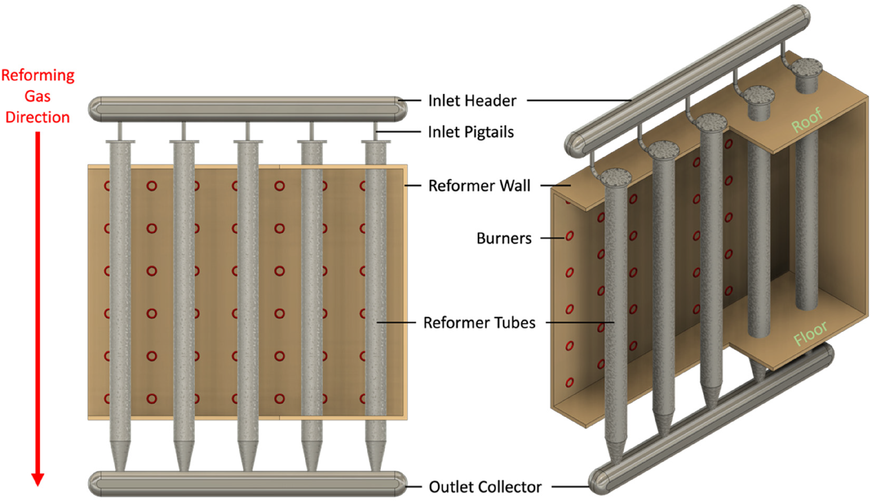
Schematic of a hydrogen reformer, showing where reformer tubes are situated.
Following this reaction, the resultant mixture (also known as syngas) composed of mostly hydrogen, carbon dioxide, carbon monoxide and steam and is allowed to further react in a water gas shift reactor:
The process can be tailored to the thermodynamic equilibrium suiting the feedstock by altering the reforming temperature, pressure, and steam-to-carbon ratio. However, in most cases, higher temperatures favour the production of hydrogen due to the endothermic primary reaction (equation (2)). 5
Metallurgical challenges for reformer alloys
The high temperature and pressure, along with carbon-intensive atmospheres, lead to two main modes of degradation of reformer tubes: carburisation and creep. The chemical reaction within the reformer leads to carbon (coke) formation, which often leads to coke deposits on the surface of reformer tubes. This coke deposition combined with the high temperatures, enables carbon diffusion into the bulk alloy, a phenomenon known as carburisation. 6 Since modern reformers operate under high temperatures (>1000 °C) and pressures (3–4 MPa), both carburisation and creep become significant degradation mechanisms. Over extended periods, this combination ultimately leads to loss in mechanical integrity, resulting in catastrophic failure of tubes.
Murkin and Brightling 7 highlighted the significance of material resilience to degradation, as both historic and current operating temperatures and pressures are limited by the strength and environmental performance of the materials used. Imminent increases in the throughput and efficiency of the reformers are required to satisfy the rapidly growing demands for hydrogen. However, reformer materials have seen limited advancement in the past three decades, inhibiting reformer developments.
Cromarty and Hooper 8 reviewed the prospects of increasing the throughput of hydrogen plants and highlighted the limited prospect in increasing feedstock conversion efficiency. Lutz et al. 9 provided a detailed thermodynamic analysis that supports this, confirming that reformers are already operating at temperatures and conditions close to the theoretical limits of the reforming reactions.
In addition, premature failures are becoming increasingly common, indicating that existing materials are pushed beyond their design limits.10–12 It is also more economically favourable to increase the throughput of existing reformers compared to the redesign and construction of new reformers. Therefore, it is preferable that improvements can be implemented in both existing and future reformers.
There are two main approaches for increasing reformer flux without altering the reformer design, explained as followed:
Increase reformer temperature such that the duration required for reaction gases to completely react is reduced.
8
Reduce tube wall thickness enabling an increase in the internal tube diameter, and consequently catalyst volume and production capacity, whilst also reducing the thermal gradients across the tube wall for improved thermal conduction and fatigue resistance.
13
Both these aspects are directly influenced (and currently limited) by the properties of reformer tube materials, calling for the urgent development of novel material solutions. Improved material performance can also contribute to the reformer lifespan, reducing the capital cost and environmental impact per unit of H2 produced.
Historical developments of reformer alloys
Since the invention of the modern steam-reformers in the 1930s, materials used for reformer tubes have seen drastic development that has enabled the operating conditions and efficiencies observed today.7,14
The development of reformer alloys can be divided into three generations, with each generation determined by a combination of change in composition, manufacturing methods, microstructural characteristics and the resultant creep strength.
Early developments
Early reformers adopted wrought 18Cr-37Ni HT-series alloys for reformer tubes, selected for their high resistance to thermal shock, oxidation and carburisation. HT alloys provided sufficient creep rupture strength for early generations of reformers, but with the major downside of high costs arising from the high Ni-content. At this point, manufacturing also posed an additional challenge; due to hot working limitations, large tube wall thicknesses were required, with the alloy carbon content severely limited. 15
First-generation alloys
The 1950s saw the biggest advancements in reformer metallurgy, with the simultaneous introduction of centrifugal casting techniques and novel compositions. The lower Ni, and consequently cheaper 25Cr-20Ni-0.4C HK-40 alloy emerged, which possessed a creep strength equivalent to that of HT alloys. 16 However, wrought HK-40 still posed significant limits on operating conditions, limiting operations to only 1–4 bar absolute pressures, and outlet temperatures of 730–800 °C. 7 The simultaneous adaptation of centrifugal casting allowed increased freedom and control in compositional design (primarily C content) as the limits imposed by hot working no longer applied.
Early work carried out by Estruch and Lyth 17 on centrifugally casted tubes showed that HK-40 can withstand stresses up to 7.1 MPa at 1000 °C, versus a maximum of 4.9 MPa at 982 °C for different variants of HT alloys for 100 000 h creep rupture stress. Centrifugally cast HK-40 possess a grain structure consisting of coarse columnar grains on the outer diameter (OD) that slowly transition into equiaxed grains on the innermost diameter, with a network of intergranular primary M7C3 carbides, where M is mostly Cr.
Upon exposure to service conditions, the primary M7C3 carbides transform into the more thermodynamically stable M23C6. The release of C from this transformation, coupled with the rejection of C from the matrix, further leads to extensive secondary intragranular M23C6 precipitation; this is discussed in further detail in the ‘Physical metallurgy of modern reformer alloys’ section. This secondary precipitation is vital to the increased creep resistance, as the fine carbides act as barriers for dislocation motion, providing significant improvement in strength. 18 Balanced with the relatively low cost compared to the HT-series alloys, HK-40 quickly became the material of choice for fired tubes.
By the end of the decade, cast HK-40 had completely displaced its predecessors and dominated the market for reformer alloys until the 1970s. The improvement in performance exhibited by HK-40 also permitted harsher operating conditions for the reformers, which were consequently raised to pressures of about 1.6 MPa at 800 °C.
Despite these improvements, HK-40 is prone to degradation due to the coarsening of primary carbides, dissolution of secondary carbides, as well as carbide coalescence. In addition, σ-phase formation is also observed, and is known to lead to the loss of strength and ductility.19–21 The loss of creep strength due to less dislocation barriers, combined with the loss of creep ductility, ultimately leads to failure of the reformer tube. 22
Second-generation alloys
In second-generation alloys, two main approaches were used to address the carbide stability problems encountered in HK-40; altering the phase stability of the carbides and strengthening of the overall alloy.
Early 1970s saw the addition of 1.5w.t.%Nb to the HK-40 base composition produced by Inco Limited, with the resultant alloyed named IN519. The added 1.5w.t.%Nb resulted in the precipitation of the MC carbide for improved strengthening, providing up to a 25% strength increase compared to HK-40. 23 A different approach resulted in the HP-40 alloy, with the nominal composition 25Cr/35Ni. HP-40 was a brief interim composition occurring around the same time as IN519. The increased Ni-content retarded the formation of the embrittling σ-phase, improving strength retention during service, albeit the solid solution strengthening effects from the extra 15w.t.%Ni remained minor, with little improvements in creep strength. 24
However, HP-40 offered drastically improved carburisation resistance compared to both HK-40 and IN519, directly contributing to a better lifespan of reformer tubes. The extra 15w.t.%Ni was found to improve carburisation resistance by approximately 45%. Combined with alterations to the Si content (additions of up to 2w.t.%), the resulting alloy exhibited a 50% increase in overall carburisation resistance compared to HK-40. 25
This second generation of reformer alloys mainly offered extended lifespan, and minor tube wall thickness reductions, with both IN519 and HP-40 displaying highly desirable characteristics individually. Yet industry remained hesitant in adopting these alloys due to their higher costs and relatively minor improvements. Therefore, shortly after in the mid-1970s, came the revolutionary ‘combining’ of the two alloys.
Third-generation alloys
In 1975, the 25Cr/35Ni/1Nb nominal composition was introduced. This composition was later coined HP-Mod and began a period of intense competition in the development of reformer alloys. The creep resistance offered by HP-Mod alloys at 950 °C was advertised to be an impressive 100% increase compared to HK-40. HP-Mod also exhibited superior retention of creep strength up to 1050 °C. 15 Other manufacturers closely followed suit, producing alloys of similar compositions, which reinforced HP-Mod as the basis of modern-day alloys.
Design approaches then shifted to further stabilise and improve the HP-Mod base alloy with the use of minor alloying additions, with the resultant composition generalised under the HP-Micro term. The minor additions resulted in the alloy being up to twice as strong compared to HK-40, whilst not being twice the price. The significant effects of minor additions also permitted a higher degree of tailoring of alloy properties according to individual users’ needs at a reasonable cost. Over the course of four decades, manufacturers experimented with many elements such as Ti, Mo, Zr and even rare-earth elements such as Y, aiming to unleash the maximum potential of the HP-Mod base composition.
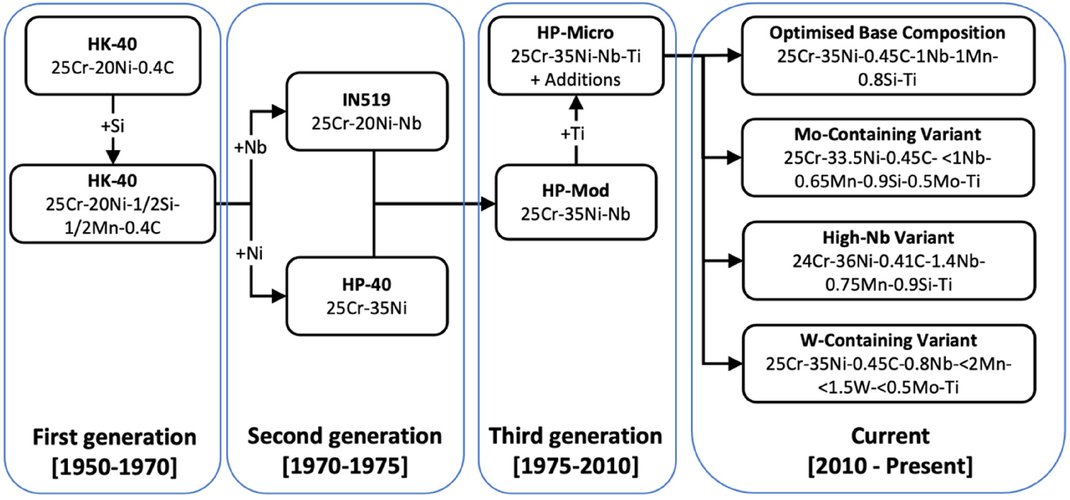
To this day, HP-micro alloys remain the material of choice for reformers. The inimical conditions encountered in present day reformers are often in the range of 3–4 MPa pressures, and temperatures of 900–1000 °C. Figure 2 summarises the evolution in the past three generations that led up to the current compositions. It is important to note that the compositions stated here are examples of compositions readily available.
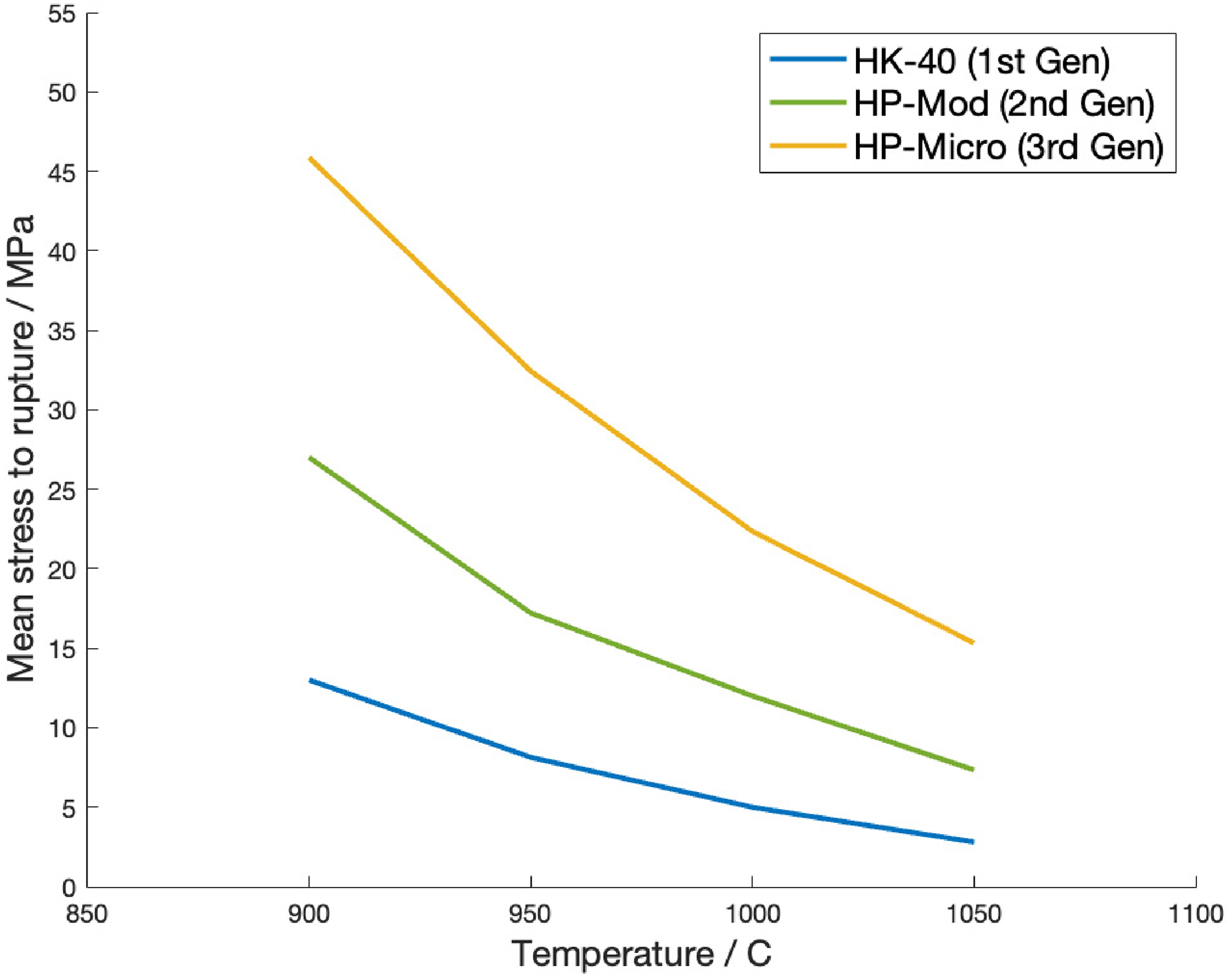
Comparison of the mean stress to rupture in 100 000 h for the three generations of alloy is shown in Figure 3. For every new generation, the mean stress was found to have approximately doubled at all temperatures, enabling the operating conditions currently utilised.
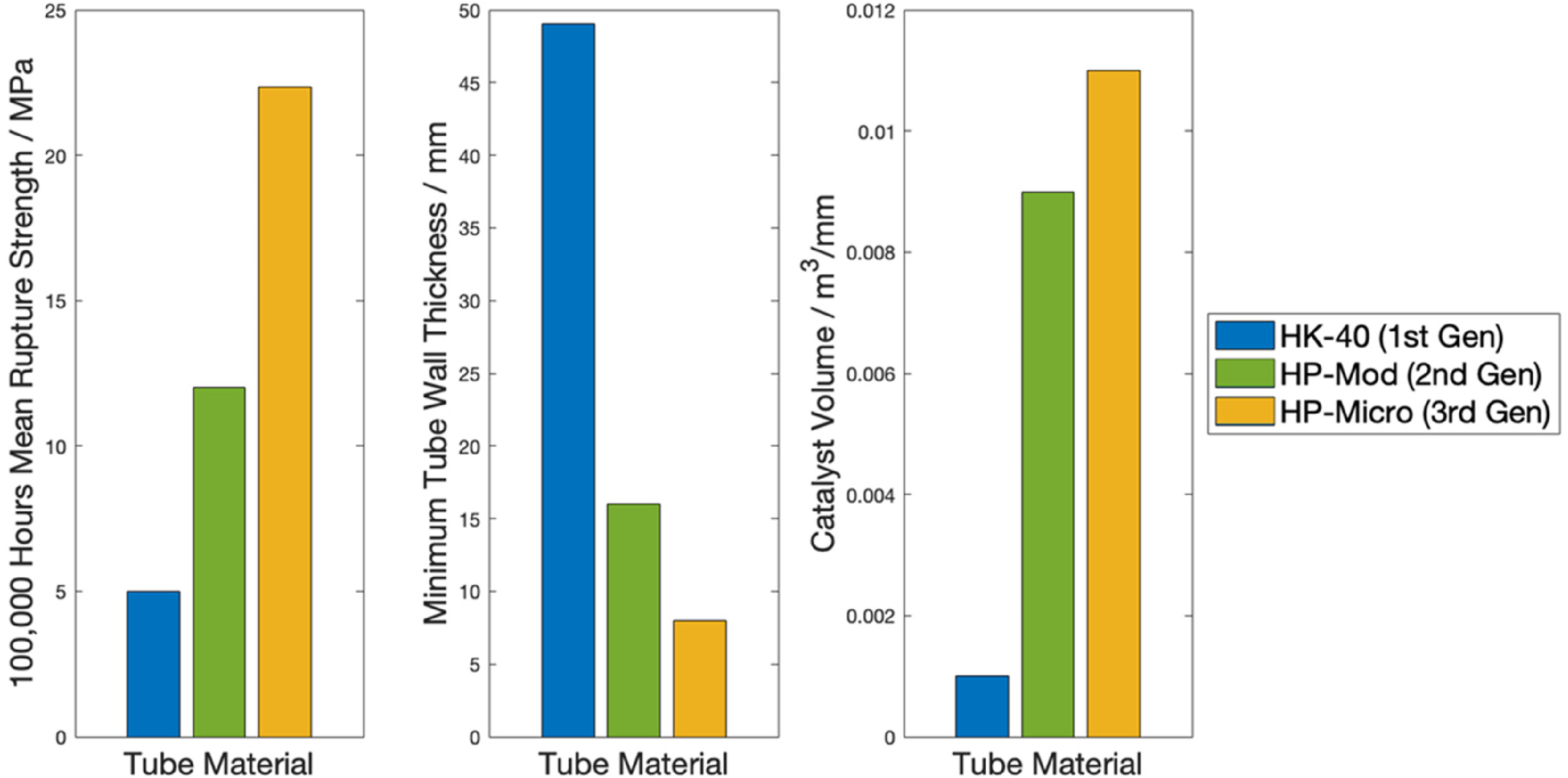
The increase in rupture life at higher stresses is of high significance, particularly in allowing an increase in operating temperatures, and/or subsequent reduction in tube wall thicknesses. The demonstratable increase in rupture strength, illustrated in Figure 4, enables increased catalyst volumes through the reformer assemblies, resulting in improved throughput.
Recent developments of third-generation alloys
The developments in composition observed in the third-generation alloys during the years of 1995–2010 contain significant insights that have informed the development of existing alloys. In this 15-year time span, alloy compositions have maintained a nominal composition of 35Ni/25Cr/0.4C/1Mn. However, other alloying elements have also been utilised at varied concentrations. For example, Nb and Si have been considered to be integral additions since the 1970s, but their contents have varied between 0.4–1.5w.t.% and 0.8–1.8w.t.%, respectively. More common minor additions include 0.05–0.5w.t.%Ti, 0.03–0.5w.t.%Mo and 0.08–1.5w.t.% Mn, while impurity elements such as S and P have been minimised below 0.03w.t.%.32–44
However, the variety of minor additions used complicate the centrifugal casting process, as some elements may suffer from problems such as evaporation. This has likely contributed to the differing strengths achieved in ostensibly highly similar compositions. The detailed effects of elemental additions are examined in more detail in ‘Evolution of alloying additions in reformer alloys’ section.
Manufacturing of reformer tubes
As alluded to in previous sections, seemingly identical compositions can result in tubes with different properties, with the root cause associated with the casting process used during production. Since its introduction, horizontal centrifugal casting has remained the dominant manufacturing method for reformer tubes.
Centrifugal casting
The adaptation of centrifugal casting techniques was one of the most revolutionary changes made to reformer tube manufacturing. The process allows for a much higher degree of compositional freedom to be achieved, whilst maintaining dimensional flexibility and providing materials with good creep properties deriving from the resultant microstructure. 45
In simple terms, centrifugal casting involves solidifying molten metal under centrifugal forces exerted using a rotating mould. Molten metal is fed into a rapidly rotating mould (usually around 1000 RPM). The mould is coated using refractory materials, as this enables easy removal of the casting. 15 The interior surface is often rough, which is later machined off using boring processes. 46 A basic centrifugal casting setup is shown in Figure 5.
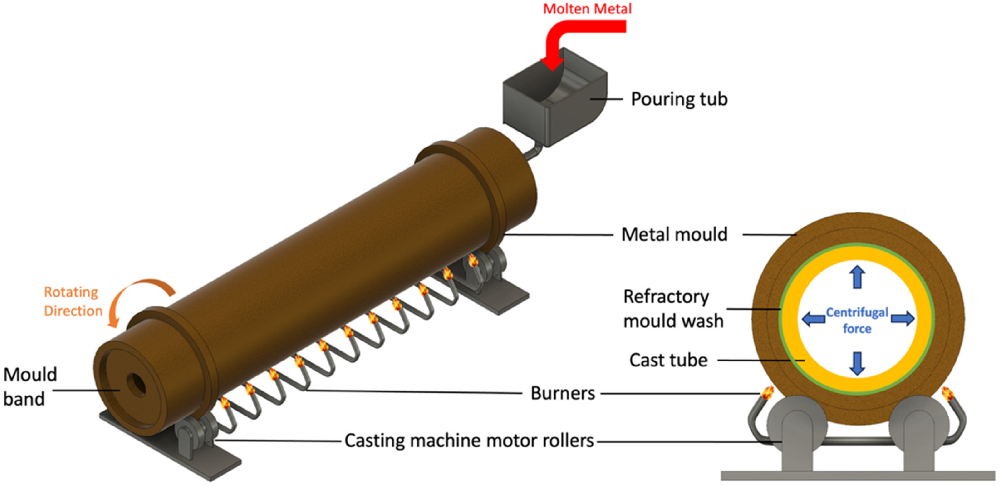
Schematic showing a typical centrifugal casting setup.
During solidification, the melt experiences a centrifugal force (G-force) of around 100 times gravity, resulting in an even distribution of a uniform thickness of the alloy melt along with the length of the mould. The high pressures developed in the mould cause non-metallic inclusions and evolved gasses to separate out of the melt towards the inner surface, resulting in a clean and dense casting. 45
Influence of solidification conditions on resultant microstructure
Heat removal occurs via the mould wall, with solidification beginning on the surface of the casting directly in contact with the refractory-coated mould wall. This leads to true directional cooling and solidification. The initial high cooling rates result in the formation of a very thin layer of fine equiaxed region on the outer diameter (OD). The subsequent reduction in cooling rate due to heating up of the mould and simultaneous reduction in melt temperature, combined with the directional solidification, leads to a region of large columnar grains. Solidification is completed upon the solidification of the internal diameter (ID), consisting of coarse equiaxed grains. 47 Figure 6 is an example of the through-wall microstructure from the ID to the OD of a reformer tube.
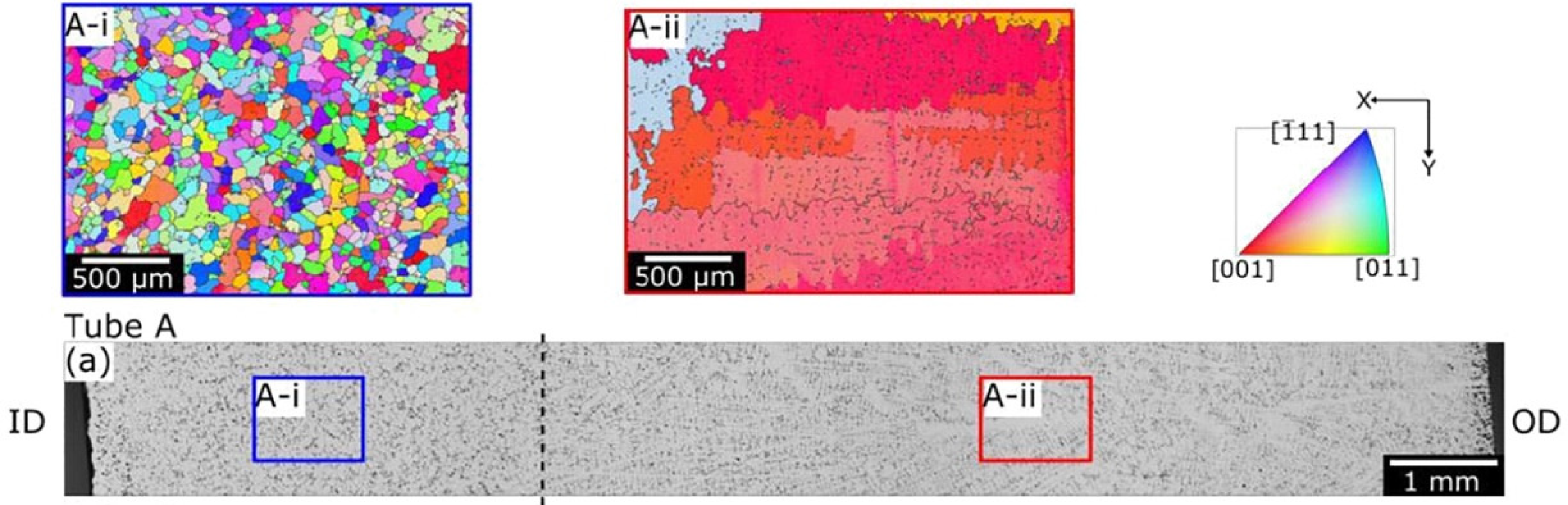
EBSD maps of the grain structure at the inner and outer tube regions showing columnar grains near the outer diameter and equiaxed grains near the inner diameter. 48 The exact regions from which EBSD data was collected are shown in the optical image. The dashed line shows the grain structure transition, with equiaxed grains accounting for approximately 25% of the wall thickness. Reproduced with permission from Elsevier.
It is believed that for optimal creep properties, columnar grains should account for at least 75–80% of the tube wall cross-section.13,49 However, consistently achieving this proportion in practice remains challenging. Overall, it has been generally agreed upon and supported by experimental results such as by Buchannan et al. 50 and Ray et al., 51 that higher cooling rates result in more columnar grains.
Interestingly however, a mismatch in the frequencies that columnar microstructures are observed in as-cast tubes, versus tubes analysed post failure, exists in the open literature. Many papers showcase as-cast microstructures often consisting of ∼80% columnar grains. In contrast, the open literature regarding post-failure analyses makes little reference to the presence of columnar grains.13,32,48,52,53 This phenomenon can be explained by potential microstructure evolution during service, but studies on recrystallisation or abnormal growth of grains occurring in reformer alloys remain limited. Therefore, there is no direct evidence to whether the ability to control the grain structure in mass-produced tubes is fully understood or achievable in daily practice.
Centrifugal casting remains a relatively labour-intensive casting process, manipulable in a range of ways. Careful control of the process is integral in producing high-quality tube castings, with some examples of key manufacturing variables discussed below.
Casting process control
A key first consideration of the manufacturing process is the type of mould used, as well as the thermal insulation effects resulting from the type or thickness of refractory mould washes, that can directly influence the cooling rates encountered by the melt. 53 Good adhesion of the melt to the mould wall allows efficient and consistent cooling, creating a robust casting with a consistent microstructure along with the tube length.
However, the rotational speed of the mould is arguably the defining characteristic of centrifugal casting, vital to the successful casting of good quality components. 54
The rotational speed must be sufficient to create the centrifugal force needed to force the molten metal against the mould wall, preventing ‘raining’ of the liquid metal while it occupies the upper-half of the mould.45,47 In some cases, though not essential, the rotational speed may also be increased/decreased at certain stages of casting. For example, the rotation speed during pouring may be lower for the melt to ease the melt flow along with the length of the mould, before increasing the rotation speed for solidification. 47 Poor control of the rotational speed can lead to problems such as poor surface finishes (too slow), or microstructure inconsistencies for example grain refinement caused by vibrations from excessive rotational speeds, ultimately leading to the rejection of the tube for quality control. 55
The centrifugal force developed also affects the flow rate of the melt through the mould length, leading to localised fluctuations of solidification conditions. Banding of the microstructure is an example of a microstructural inconsistency that can arise from the variation of cooling rates due to liquid mobility resulting from viscosity variations, or partitioning effects due to the mobility of elements.
In summary, the rotational speed must be carefully controlled to be high enough to prevent raining, promote good melt to mould adhesion and ensure the even distribution of melt in the mould; all whilst being able to keep the solidification rate within a pre-determined range to give the desired microstructure.
Examples of additional variables during the casting process include pour speeds and the application of electromagnetic fields. Pour speeds and temperature primarily affect the fluid flow within the mould. Generally, lower pouring temperatures reduce the solidification times, and result in grain refinement. However, this is often limited by other practical challenges, such as volatilisation of certain elements.
Electromagnetic fields may also be applied to the melt during solidification and can aid the control of the resultant proportion of columnar grains. 56 However, this remains a less common practice within industry due to the added complexity. Overall, centrifugal casting remains a highly complex casting procedure, due to the combined effects arising from small alterations to the casting process.
Physical metallurgy of modern reformer alloys
Modern HP-Micro alloys possess characteristics inherited from their predecessors, and typically have a general structure of a network of carbides embedded in an FCC matrix.
Strengthening in reformer alloys
The strength and mechanical performance in reformer alloys is governed by the combination of solid solution strengthening and precipitate strengthening. The FCC matrix confers good ductility and toughness and is able to maintain its creep properties at high temperatures owing to low diffusion activation rates. Additional strength is then imparted through solid solution strengthening achieved through alloying, resulting in a chemically complex matrix.
Solid solution strengthening arises by introducing interstitial and/or substitutional atoms within the crystal lattice. Introducing foreign atoms induces lattice distortions and strain fields that in turn interact with the strain field around dislocations, increasing the difficulty for dislocation motion. Common solid solution strengtheners in austenitic steels include N and Mo. 57
The typical microstructure and its evolution as a function of exposure to operating conditions of a HP-Micro alloy is illustrated in Figure 7, showing the key differences in the as-cast state versus aged conditions.
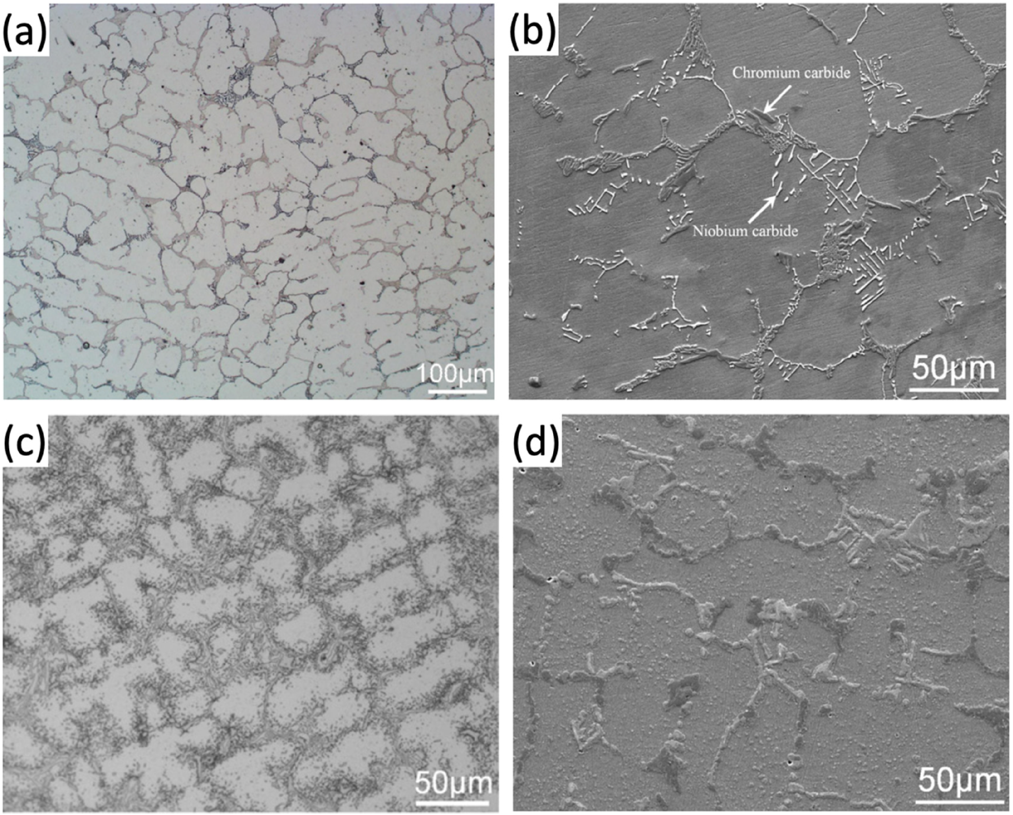
Scanning electron (SEM) and optical (OM) micrographs illustrating microstructure evolution of typical HP-micro alloy: (a) as-cast (OM), showing primary carbide network; (b) as-cast (SEM), showing the differing contrast of chromium and niobium carbides; (c) 1008 h aged at 900 °C (OM), showing extensive secondary precipitation around primary carbides; (d) 160,000 h ex-service aged (SEM) at around 900 °C showing the coarsening and coalescence of primary carbides. 64 Reproduced with permission from Elsevier.
During solidification, primary carbides and carbonitrides, most commonly types M7C3, M23C6 and MX (with M denoting metal atoms and X denoting C and/or N), are formed. Generally, carbides are preferred over nitrides or carbonitrides, which have a tendency to adopt needle-like morphologies, leading to the embrittlement of the matrix. 58
Very often, metastable M7C3 forms at grain boundaries during solidification, with varying morphologies from lamellar to globular. Whereas M23C6 often results from the transformation of intergranular M7C3 due to better thermodynamic stability of M23C6, or through intragranular precipitation from the C-supersaturated matrix. 59
Intergranular carbides inhibit grain boundary sliding, which dominates in high temperature low stress conditions. Skeletal and/or lamellar carbides are especially preferred. This is because skeletal carbides can increase resistance to creep crack growth, while lamellar carbides force cracks to propagate around them, therefore increasing the time to failure.51,60 In addition, intragranular carbides inhibit dislocation motion within the matrix; in the case of reformer alloys, secondary M23C6 plays the key role in retarding dislocation climb during deformation.61–63
MC carbide
The MC phase primarily forms intergranularly and is enriched in strong MC carbide forming elements such as Nb, Ti, Zr and Ta. 65 Often considered to be the more thermodynamically stable grain boundary carbide, it provides strength via pinning of grain boundaries, thus suppressing grain boundary sliding.18,65
However, MC is not immune to degradation brought on by long-term service, with its decomposition often leading to the formation of the complex silicide G-phase or the M6C η-phase.
G-phase adopts an FCC crystal structure, with a lattice parameter of 11.2 Å, and has the general formula of A16B6X7, where A and B denote transition metal elements, and X is a group IV element. 66 The Ni16Nb6Si7 variant most often observed in reformer alloys was first identified in HK-40 variants by Barbabela et al. 67 It is predominantly found on grain boundaries (hence its name), and is only observed after high-temperature exposure.
The M6C η-phase adopts a diamond cubic structure with a lattice parameter of ∼11.08 Å and has primarily been reported in studies prior to the 1990s. In reformer alloys, it has the tendency to form Nb-Ni-Si rich variants, making its composition similar to G-phase. Distinguishing between η and G-phase has been known to be challenging, due to their similarities in composition and lattice parameters, further complicated by double diffraction effects of the diamond cubic structure.68,69 Studies by Williiams et al. 69 and Kenik et al. 70 speculated that η-phase formation can be attributed to the alloys’ carbon content, but lacking support from other studies, this hypothesis remains unconvincing. However, since it is now rarely observed in modern generation alloys, with G-phase much more frequently reported, η-phase has now become a phase of less concern.
What is clear however, is the formation mechanism of G-phase, which arises from the enrichment of Si in NbC. G-phase often nucleates around the NbC interface, and grows inwards into the NbC until the whole carbide is transformed. A key factor that drives the formation of G-phase is the tendency for Si to segregate at interdendritic boundaries.43,71 This hypothesis was recently validated by work conducted by Vaché et al., 71 using a combination of TEM and focused ion beam/SEM nanotomography.
A consequence of the transformation of NbC into G-phase is C being rejected into the matrix, resulting in the precipitation of M23C6 carbides around the G-phase. 72 Usually, excess C simply results in the precipitation of M23C6, which should not be detrimental to creep properties. However, at the point of G-phase formation, the alloy will have been in service for a prolonged duration, with dense dislocation pile-ups present around grain boundary carbides. Preferential nucleation of M23C6 along with dislocations can therefore result in the formation of elongated (and sometimes needle-like) M23C6, leading to embrittlement. 67
Over the years, the role of G-phase has remained controversial, with its exact effects remaining elusive. De Almeida et al. 73 suggest that the G-phase/matrix interface acts as a preferential site for creep damage. Loss of strength is also exacerbated by the simultaneous dissolution of NbC during the transformation.10,74
However, some reports in literature have argued that G-phase can be beneficial. 75 For example, Tancret et al. 76 highlighted the possibility of confusion between the effects of Si versus the effects of G-phase formation; suggesting that G-phase formation is beneficial to the creep strength by reducing the Si-content in the matrix.
Regardless, it is widely agreed that the alloy's Si-content is one of the most influential factors that controls the G-phase formation kinetics, with Si favouring the decomposition of NbC into G-phase. 77 In addition, an observation that has not been extensively scrutinised is the morphology changes that accompany G-phase transformation. G-phase is always observed to possess a blocky/spheroidised morphology, and existing literature has yet to investigate the effects of the morphology evolution of NbC prior to transformation on the creep strength.
M7C3 and M23C6 carbides
In most alloys, the M7C3 carbide, most commonly enriched in Cr, is the next carbide phase to precipitate following the MC carbide as solidification progresses. Eutectic M7C3 often adopts a skeletal Chinese-script morphology and is almost exclusively formed along with grain boundaries.16,78
Detailed explanation for the formation of M7C3 upon solidification during centrifugal casting remains extremely limited, but a general consensus is that it is attributed to the relatively high cooling rates during centrifugal casting limiting solute redistribution. Upon high-temperature exposure, primary M7C3 transforms into the more thermodynamically stable M23C6 carbide, that is, also Cr rich and adopts an FCC crystal structure. 66
In recent years, this transformation has been extensively investigated to understand the transformation driving force and its subsequent ramifications. The transformation can be considered in two parts: the transformation of the primary M7C3 into M23C6, and the extensive, intragranular secondary precipitation that follows.
Wang et al.
78
closely examined the transformation of the primary M7C3 to M23C6 and provided clear evidence on the mechanism of the first part of the transformation. The transformation begins on the M7C3-matrix interface, driven by the thermodynamic stability of M23C6 compared to M7C3.
65
In addition, the improved coherency of M23C6 with the FCC matrix leads to accelerated transformation kinetics. As the M7C3 destabilises upon exposure to service conditions, C diffuses out of the carbide and is released into the matrix. This is justified by the small (∼5%) volume shrinkage observed for a given amount of M7C3 transforming versus a calculated 56% growth if the diffusion was dominated by Cr diffusion into M7C3. Newly formed M23C6 also exhibits an orientation relationship with the M7C3 given by
C released from the transformation begins the secondary precipitation process. Before examining the detailed mechanisms more closely, regards must be paid to the resultant microstructure. In most reformer alloys (regardless of compositional variations), resultant aged microstructures often exhibit a thin precipitate-free zone (PFZ) directly adjacent to primary carbides, a high-density precipitate zone (HPZ) situated a few microns from primary carbides, and a low-density precipitate zone (LPZ) further into the matrix around the centre of a grain.
Intragranular secondary carbides do not nucleate on any primary carbides, but instead form directly from the matrix. A cube-on-cube orientation relationship exists between intragranular secondary M23C6 carbides and the matrix, given by
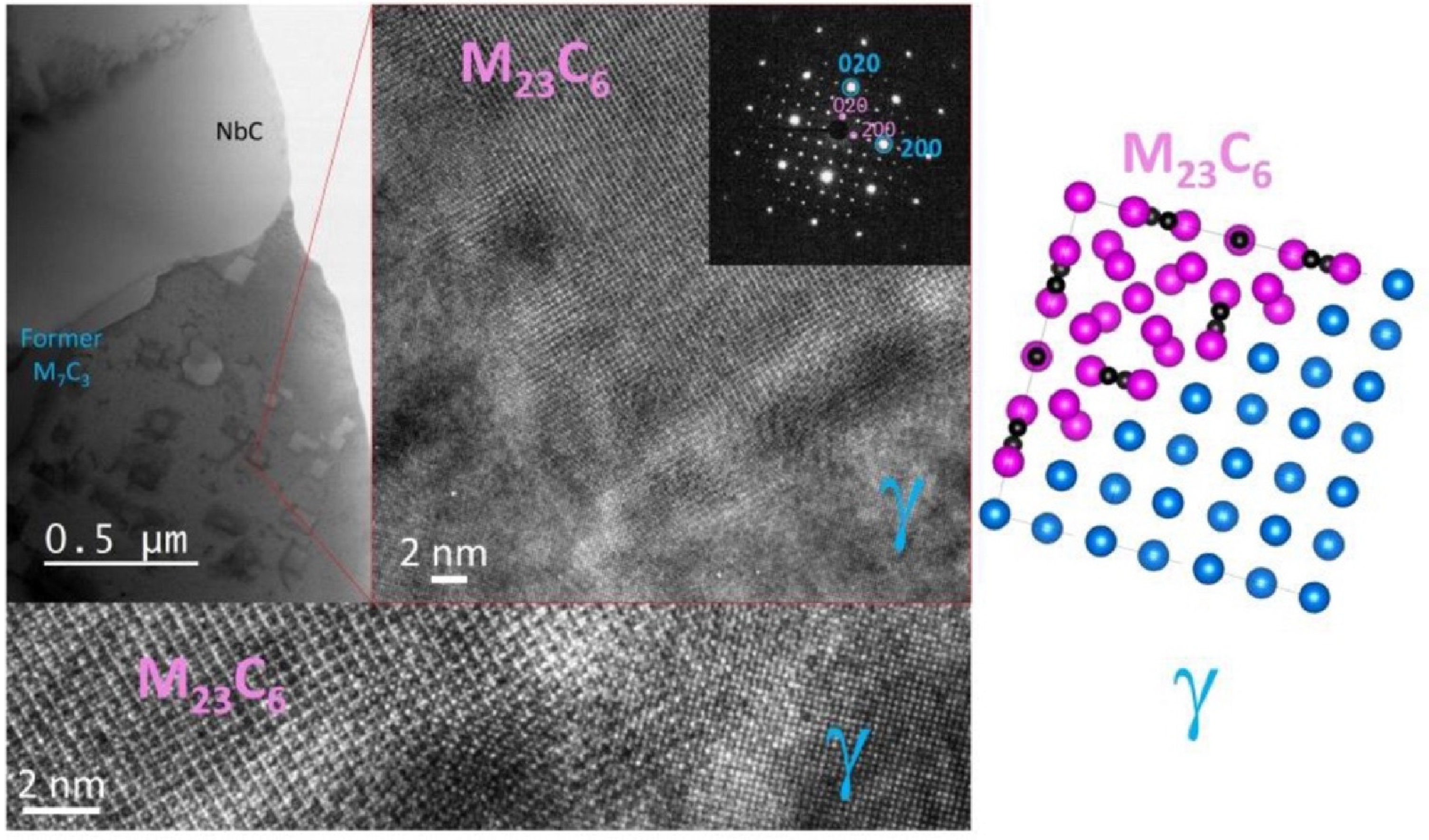
TEM images (Bright field, high resolution and SAED pattern in (001) zone axis) showing secondary M23C6 carbides that have nucleated and grown during aging at 750 °C for 112 h in the austenitic matrix with a cube-on-cube orientation relationship. 79 Reproduced with permission from Elsevier.
Since C is a fast diffuser, it soon diffuses past the Cr-depleted zone, and secondary precipitation begins in the soon-to-be HPZ. In this region, extensive secondary M23C6 precipitation occurs intragranularly, heterogeneously nucleating near imperfections such as dislocations and stacking faults. 59 Faster-growing M23C6 then begins to coarsen driven by Ostwald coarsening. Simultaneously, free C atoms continue to diffuse further into the matrix. This ultimately results in the HPZ, which is observed to grow as exposure time increases, with larger precipitates found near primary carbides. 79
As secondary precipitation advances, the available C atoms decrease with increasing distance from the region of primary carbides. This results in low number density of precipitates forming, ultimately leading to the LPZ in the centre region of a grain, that can be more pronounced for larger grains.
During service, prolonged exposure to high temperatures leads to the evolution of M23C6 carbides. Compared to the MC carbide, M23C6 is more prone to growth and coalescence, leading to larger and more interlaced carbide networks.16,80 This is undesirable as interlaced carbide networks act as easy crack propagation routes through the alloy bulk. 81 Moreover, spallation and regeneration of oxide scales can cause localised Cr-depletion, leading to the dissolution of Cr-carbides, resulting in loss of strength. 38
As illustrated, the M7C3 to M23C6 transformation is a complex process, with constant compositional fluctuations, as well as influence from driving forces for coarsening. In addition, in 2019, Tancret et al. 76 suggested that the transformation could be a potential cause for the early degradation of creep properties, a hypothesis also proposed by De Almeida Soares et al. 75 in the 1990s.
In recent years, there has been little research to show the possibility of directly forming M23C6 upon solidification.80,82 This is thought to be achievable by either utilising a lower solidification rate or elements (e.g., Nb) to manipulate carbon availability during solidification.48,83
Heretofore, achieving primary M23C6 in as-cast microstructures in order to reduce phase transformation, and therefore the driving force for elemental diffusion, remained a far-fetched idea due to practical casting and cost limitations. However, with the new demand for better performing alloys, this is now becoming a topic that merits more thorough investigation.
Evolution of alloying additions in reformer alloys
Linked to the need for improved alloy performance governed by microstructural modifications, alloy compositions have evolved significantly throughout the years, with the developments aiming to harness the synergistic effects of different elements.
Essential additions
Essential additions in reformer alloys have three main functions: to stabilise and maintain the FCC matrix at all temperatures, provide protection against environmental degradation, and to allow the formation of carbide networks for strength. Due to the strong desire for cost reduction in reformer alloys, Fe is used as the base element and engineered to develop the desired characteristics using other alloying additions.
Nickel (∼35w.t.%)
Ni is indispensable in suppressing the FCC to BCC transformation of Fe. In order to combat the BCC-stabilising effects of Cr, 15w.t.%Ni is the minimum required to maintain FCC at all temperatures. 57 In addition, Ni contributes to the carburisation resistance of the alloy. This led to early HK-40 alloys comprising of 20w.t.%Ni additions. Significant additions of Ni also encourage carbide precipitation by reducing carbon solubility in the matrix, helping give rise to the characteristic microstructure. 84 The later adapted 35w.t.%Ni in HP alloys provided further improvements in carburisation resistance and aided the retardation of σ-phase formation, which can be detrimental to mechanical properties.6,24,85
Chromium (∼25w.t.%)
Cr forms the basis of corrosion resistance and strengthening, by allowing the formation of a continuous chromia (Cr2O3) oxide layer and the precipitation of Cr-rich carbides. 86 Cr content has been optimised to provide sufficient environmental protection (and regeneration in case of oxide scale volatisation or spallation), whilst also tailored to prevent the formation of deleterious phases, such as the σ-phase. This is important because topologically close-packed phases such as σ-phase can form with excessive Cr, leading to embrittlement and affecting carbide precipitation.
Carbon (0.4–0.5w.t.%)
C acts as another FCC stabiliser, but is more importantly used to allow the precipitation of the strengthening carbide network. Increasing C directly increases carbide fractions. However, the content is often kept at around 0.45w.t.%C to prevent excessive carbide precipitation.87,88
Yan et al. 81 increased C content in a W-containing HP-mod alloy, with results showing larger and more interlaced carbides, as well as the formation of primary M23C6. Xiang et al. 89 produced similar results in terms of carbide fraction increases in a HP-mod alloy, but primary carbides were believed to be a mix of M7C3 and M23C6. This discrepancy is therefore likely to be attributed to the difference in W-content and is not achievable with only altering C-content.
Niobium (0.5–1.5w.t.%)
Niobium as a strong MC carbide former was first introduced in IN519. It causes the partial replacement of Cr-carbides with the more stable NbC carbide, whilst refining and fragmenting the primary carbide network.75,90 The use of Nb in reformer alloys has soared from ∼0.8w.t.% to ∼1.5w.t.% in the 2000s. Alloys with increased Nb contents posed problems with maintaining their strength due to secondary Cr23C6 precipitation being retarded at temperatures below 900 °C, inevitably resulting in the reversal of the increase around 2010.68,75
A curious facet is the evolution in operating conditions; with reforming temperatures currently standing at over 1000 °C, temperature fluctuations could lead to tube wall temperatures in excess of 1100 °C.91,92 Therefore, perhaps it would be worthwhile to re-examine if Nb contents have room for further engineering for improving alloy properties, as well as higher damage tolerance, due to the MC carbides’ better resilience to coarsening at high temperatures.42,93,94
Manganese (<2w.t.%)
Mn is an element for which its individual effect on reformer alloys remains ambiguous. Mn is considered to be a relatively cheap element, that can act as an FCC-stabiliser (albeit only half as effective as nickel) and a weak carbide former. However, the additions of Mn in reformer alloys are likely due to Mn being an effective deoxidiser prior to casting. Mn is advantageous compared to other common deoxidisers such as Si and Al, as it is not prone to induce the formation of additional phases.57,95
Although relatively neutral, excessive Mn can be pernicious to environmental resistance due to the formation of a spinel MnCr2O4/Cr2O3 mixed oxide layer, instead of pure Cr2O3 scales.96,97 The less active elements (i.e., Mn) act as preferential paths for hydrogen permeation and can act as easy crack initiation points during mechanical loading, causing spallation of the oxide layer. 97
Silicon (0.4–2.1w.t.%)
Si is commonly known in many alloy systems for its effect in improving oxidation resistance through the formation of a SiO2 oxide layer in addition to (and most commonly under) a chromia scale. However, in reformer alloys, it has a multitude of effects.98,99 Early research shows higher Si contents encouraged more extensive primary MC precipitation, but this came with the tendency for Si to segregate at interdendritic boundaries.77,100 However, as previously mentioned, excessive Si inevitably causes complete transformation of NbC into G-phase; therefore, proving careful control of amounts used to be vital.77,101
Minor additions
Minor additions were sought in order to further improve the stability and/or morphology of the precipitate phases, in an attempt to increase material performance.
Titanium (<0.15w.t.%)
Ti was the first minor addition used and is still consistently used now. Ti being another strong MC carbide former, encourages primary MC formation. MC containing trace amounts of Ti is found to exhibit superior stability compared to Ti-free MC. (Nb,Ti)C shows increased resistance towards both coarsening and transformation into G-phase.22,73,101 Ti also has significant effects on the microstructure, primarily in the form of altering the MC carbide morphology; Ti is believed to encourage more blocky MC due to the increased MC/matrix interfacial energy.50,94 These effects ultimately lead to increased creep strength, ductility and rupture time, securing it as a consistently used micro-addition.22,102
Molybdenum (<0.5w.t.%)
Mo has traditionally been used to increase high temperature strength but is associated with the formation of phases such as η, σ and χ-phase.66,103,104 Unfortunately, little experimental evidence has been reported on HK/HP alloys to support the link between these phases and the Mo concentration, with manufacturers showing a lack of consistency on the uptake or elimination of Mo in compositions.
Nitrogen (<0.15w.t.%)
N is often incorporated into alloys by using nitrided ferrochrome and is an example of synergistic alloy addition, predominantly working with C to affect the carbide precipitation and behaviour, as N can result in the precipitation of nitrides/carbonitrides. 89 Attarian and Taheri 105 concluded that N is capable of decreasing carbide fractions and suggested elemental segregation to play a role in this observation. In fact, Rawers and Grujicic 106 have expressed concerns that N segregation can result in a higher likelihood of nitrides, with their needle-like morphologies causing embrittlement. Combined, this suggests the importance of being able to control the tendency of N-segregation to occur, and evaluating if benefits gained outweigh the negatives utilising N.
Yttrium (<0.1w.t.%)
Y is generally thought to be beneficial to the creep strength in reformer alloys but seems to have much more complex implications with the exact effects of Y remaining unclear. Nunes et al.107,108 identified fragmentation of primary carbides in Y-modified HP-micro alloys. This is thought to be caused by Y being a carbide former affecting the early stages of solidification, acting as extra heterogenous nucleation sites for other carbides. Y was also shown to improve cyclic oxidation resistance by Yan et al. 109 ; with the authors claiming that Y improves the adhesion and thickness of Si2O3 and Cr2O3 scales formed. Overall, research on Y in HP-micro alloys remains extremely sparse and lacks persuasiveness to support claims of Y improving creep strength.
Zirconium (<0.1w.t.%)
Zr usage has fluctuated over the years. Early work carried out by Wen-Tai and Honeycombe, 94 showed that Zr stabilised the MC carbide, making it more resistant to coarsening. Caballero et al. 110 later suggested that this was due to ZrO acting as potential nucleation sites, leading to the fragmentation of the primary carbide network. Both authors claim this results in improved creep resistance due to (Nb,Ti,Zr)C being more resilient to coarsening. However, the available studies on the effect of Zr were carried out on IN519 and a low-carbon variant, respectively, and should be approached with caution when designing newer generation HP-micro compositions.
Conclusion – implications for future alloy development
This review has sought to examine the evolution of alloy chemistry of reformer alloy compositions as linked to key challenges in microstructural evolution, and to outline key directions for the development of novel compositions that can provide materials with improved performance.
It is evident that few advancements in reformer alloys have been reported in the last 15 years, likely due to the limited amount of published research. This is believed to be primarily due to the overemphasis on tailoring minor elemental additions and the lack of understanding on the detailed effects that these elements have on phase transformations and kinetics. This overemphasis on minor elemental additions has also diverted design efforts away from consideration of the essential elemental additions and alterations to phase transformation pathways and mechanisms instead. Furthermore, the centrifugal casting process also complicates and inhibits alloy development, as a lack of understanding of the implications of specific alloying elements for manufacture limits progress.
Nevertheless, this review has shed light on exciting opportunities for future alloy design. With the expectations of reformer alloys to deliver superalloy performance at stainless steel prices, inspiration can be drawn from the developments in superalloys. With superalloy development progressing at an unprecedented rate, databases for thermodynamic calculations have seen drastic improvement in the recent years. This could potentially allow the simulation of alloy systems that are based on existing reformer alloys with the inclusion of elements more common in superalloys (e.g., La, Hf, Ta etc.), to enable exploration of a larger compositional design space. In fact, Magne et al. 111 investigated a Ta-containing alloy in 2019 and showed 0.15w.t.% micro-additions had significant effects on the microstructure. Therefore, a potential route for alloy design to utilise novel minor-additions, and to explore their effects has been identified.
However, cost remains a major concern in reformer alloys that may indeed deter manufacturers to explore more expensive compositions. Yet it should be taken into account that more expensive compositions should/could result in extended lifespan and/or increased reformer throughput. This ultimately leads to cost reduction in the long term, whilst also contributing to sustainability. Consequently, a more holistic approach towards systems engineering should be considered for reformer design.
Currently, as previously mentioned, casting control remains challenging, with seemingly identical alloy compositions resulting in different creep strengths. Future design approaches should therefore also consider the resilience of an alloy composition to casting conditions (e.g., solidification rates). An alloy that is relatively insensitive to differing solidification conditions, would be highly desired; with the alloy more reliant on its intrinsic strength, less dependent on resultant grain structure, or possessing the ability to result in similar microstructures/properties upon ageing.
In summary, this review has outlined the history of reformer alloys, showcasing how the compositions and manufacturing methods have evolved and influenced microstructural features over the years. This review has also highlighted the effects of the common existing alloying additions, as well as critically identifying the compositional design space for the development of newer generation alloys.
Footnotes
Author contributions
M.C.H. Tse, main conceptual ideas, project outline and writing of manuscript. E. R. Livera provided critical feedback and contributed to the writing of manuscript. K.A. Christofidou supervised, provided critical feedback and helped shaped the research.
Declaration of conflicting interests
The author(s) declared no potential conflicts of interest with respect to the research, authorship, and/or publication of this article.
Funding
The author(s) disclosed receipt of the following financial support for the research, authorship, and/or publication of this article: This work was supported by the Engineering and Physical Sciences Research Council, and Science Foundation Ireland (EP/S022635). Access to scientific expertise was made possible through the Royce Institute (EP/R00661X/1, EP/P02470X/1, and EP/P025285/1).