
Abstract
This article investigates the effect of N content on the microstructure, mechanical properties and wear resistance of hypereutectic high chromium cast iron (HHCCI). With the increase of N content, the primary carbides are obviously refined, the austenite content increases, and the dispersed granular Cr2N precipitates. After quenching at 1000 °C, secondary carbides are precipitated from the matrix, the matrix transforms into martensite + retained austenite. With the increase of N content, the corrosion resistance of HHCCI increases, and 0.3 wt.% N HHCCI shows the best corrosion resistance. With the increase of N content, the wear resistance of HHCCI increases. The wear resistance of HHCCI with 0.15 wt.% N is the best, which is 1.57 times that of HHCCI without N.
Keywords
Introduction
High chromium cast iron (HCCI) generally refers to white cast iron with Cr content greater than 12 wt.% and C content of 2 wt.%-4 wt.%, its as-cast structure is mainly composed of M7C3 eutectic carbides and austenite matrix. 1 Due to the presence of these hard carbides, HCCI has excellent wear resistance and has been widely used in metallurgy, mining, transportation, power and other industries. 2 O.N. Dogan 3 prepared 26 wt.%Cr-2.76 wt.%C, 26 wt.%Cr-3.07 wt.%C, 26 wt.%Cr-3.66 wt.%C hypoeutectic, eutectic and hypereutectic high chromium cast iron (HHCCI) respectively, and found that HHCCI had higher hardness and better wear resistance. In order to improve the mechanical properties of HCCI, it can be realised by composition design control, alloying and heat treatment. 4 Alloying can significantly improve the performance of HCCI, some scholars have studied the addition Ti, Ni, Mo and other precious metal elements to improve the performance of HCCI,5–8 and find that the addition of these alloying elements to HCCI can not only refine the microstructure, but also generate new hard carbides to improve the hardness and wear resistance of HCCI.
Relevant literature shows that N can regulate the microstructure and properties of HCCI. The effect of N and Ni is similar, both of which can expand the austenite phase region, but the effect is 20 times that of Ni. 9 N is a strong austenitic stable alloy element, and is usually added to austenitic stainless steel to replace part of nickel, which reduces production costs. On the other hand, N element is also considered to be a harmful element because it reduces the toughness and ductility of some steels. The addition of N to HHCCI can refine the grain size and enhance its hardness and wear resistance, and the element N can solid-solution strengthen the matrix, increase the electrode potential of the matrix, enhance the self-healing ability of the passivation film, and improve the corrosion resistance. M.M. Ibrahim 10 studied the effect of N on the microstructure and properties of hypoeutectic high chromium cast iron, and found that N could refine the eutectic carbides, and the nitrides produced lead to the increase of hardness and wear resistance of HCCI. Lu11,12 prepared hypoeutectic high chromium cast iron with a N content of 0.39 wt.%. and found that the HCCI with N addition had higher hardness and impact toughness. In the electrochemical test, the corrosion current density of the HCCI with N addition was lower, indicating better corrosion resistance. L. Xu13,14 studied the erosion wear behaviour of hypoeutectic high chromium cast iron with N content of 0.38 wt.% in alkaline mortar, and found that the M7C3-ferrite-martensite interlayer structure was formed at the interface of eutectic M7C3 carbides, and the N and Cr elements dissolved in the matrix increased the corrosion resistance and reduced the synergistic rate of corrosion and wear. H Ding 15 found that N could stabilise the austenite matrix and inhibit the formation of martensite in hypoeutectic high chromium cast iron, and N produced nitrides during liquid solidification, which could refine the structure and improve the hardness and impact toughness. However, few researchers have focused on the effect of N content on HHCCI.
In this article, the effects of different N contents on the microstructure, hardness and wear resistance of HHCCI were studied. The effect of N content on the corrosion resistance of HHCCI was also studied by electrochemical method. It is expected to provide reference for further improving the performance of HHCCI.
Materials and methods
Sample preparation and heat treatment
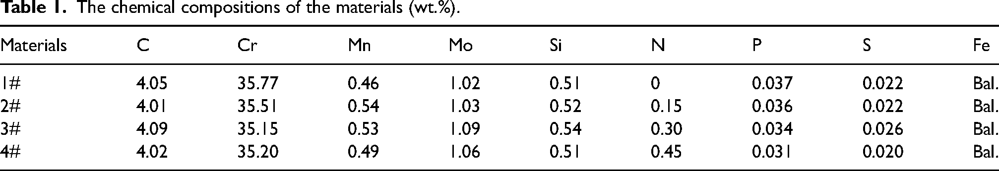
The raw materials used in the experiment were scrap steel, high-carbon ferrochrome, low-carbon ferrochrome, nitrogen ferrochrome, ferromolybdenum, ferromanganese and ferrosilicon. The samples were melted in a 50 kg medium-frequency induction furnace. During melting, high-carbon ferrochrome is placed at the bottom of the furnace. Then the steel scrap, low carbon ferrochrome, ferrochrome with nitrogen, ferromolybdenum, ferromanganese and ferrosilicon were put into the furnace in turn and heated to 1520°C for melting. The chemical composition of the specimens is shown in Table 1. According to the previous research, 16 HHCCI of 35 wt.%Cr-4 wt.%C has high hardness and good wear resistance when the quenching temperature is 1000–1050 °C. In this experiment, the heat treatment was set to 1000 °C with a holding time of 1 h, air-cooled. After quenching, the sample was tempered to eliminate the internal stress generated during quenching, and the tempering temperature was set to 250 °C with a holding time of 4 h, furnace-cooled.
The chemical compositions of the materials (wt.%).
Microstructure analysis
After coarse grinding, fine grinding and polishing, the samples were etched with aqua regia for 20–30 s. The microstructure was observed by OLYMPUS BX51 M metallographic microscope and scanning electron microscope (SEM, Gemini 300 Zeiss). Five metallographic photos with magnification of 200 x magnification were selected for each sample. The volume fraction of carbides and the equivalent diameter of primary carbides in HHCCI were calculated by Image-Pro Plus software. The equivalent diameter of primary carbides can be calculated by formula (1).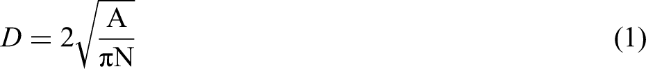
X-ray diffraction (XRD) analysis
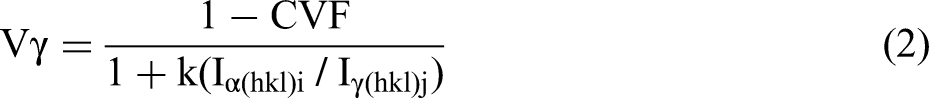
The samples were analysed by XRD with an X-ray diffractometer (Bruker D8 ADVANCE, Germany). A Cu Kα-ray source (λ = 0.15418 nm) with a voltage of 40 kV and a current of 30 mA was used, coupled with continuous scanning in the 2θ range of 30–100° with a step size of 0.02° and a scanning speed of 1.5°/min. Since N is an austenite stability element, in order to explore the phase composition of HHCCI, the content of retained austenite in the matrix is calculated by formula (2) according to XRD spectrum.
17
Mechanical property test
HBRV-187.5 Brauwell hardness tester was used to test the macrohardness with 1470 N load and 5 s residence time. The microhardness was tested using the MICROMET-5103 digital microhardness tester, the test load was 1.96 N, and the residence time was 10 s, in the microhardness and macrohardness test, 7 readings were randomly selected on the sample surface, and the average value was calculated after eliminated the maximum and minimum values.
Wear test
The friction and wear test were carried out on the MM-200 ring block wear tester, as shown in Figure 1. The sample size was 12 mm × 12 mm × 19 mm, and the grinding ring material was GCr15 steel. The test load was 196 N, the rotation speed of the test machine was 200 rmp, the wear time was 2 h. and the sample was weighed every half an hour of wear. The worn sample was ultrasonically cleaned with ethanol and dried, the mass change before and after wear was measured. The BSA2245-CW analytical balance was used to weigh the mass of HHCCI, and the accuracy was 0.1 mg. The wear resistance was the reciprocal of the weight loss. In order to understand the wear mechanism, the surface of the sample after wear was observed by SEM.
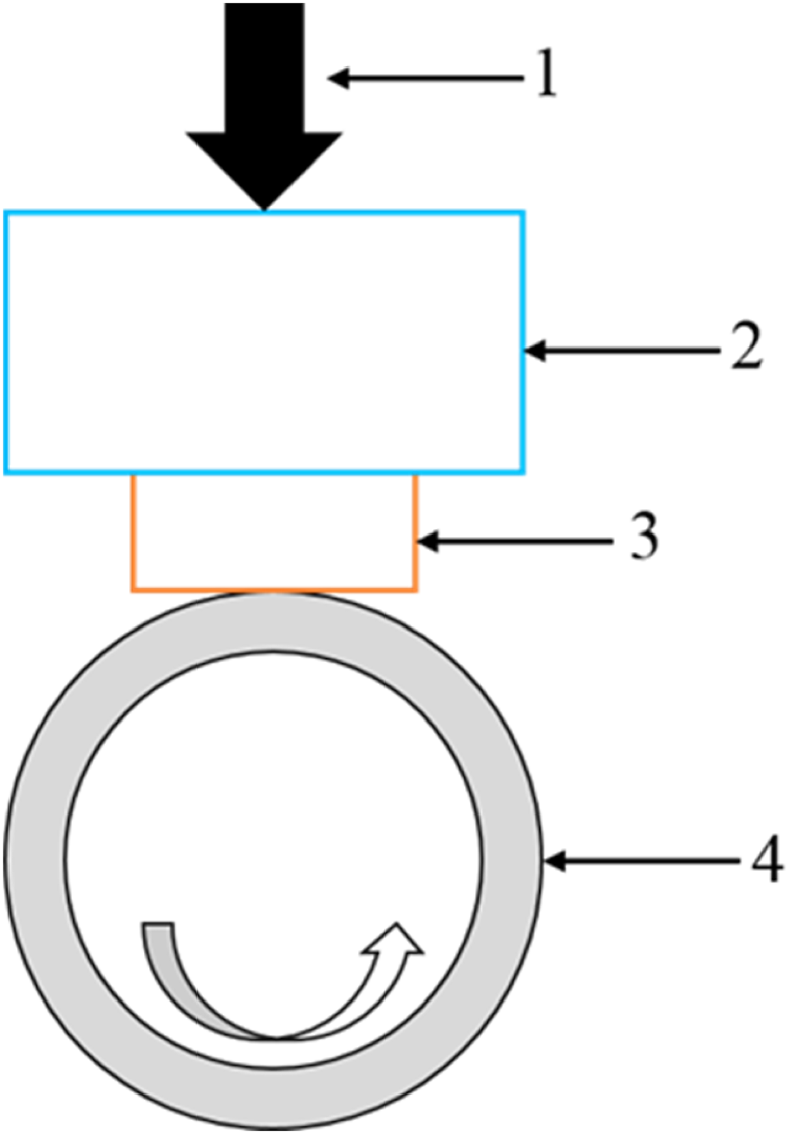
Schematic diagram of wear test: 1-load; 2-fixture; 3-test specimen; 4-grinding ring.
Electrochemical performance test
In order to evaluate the corrosion behaviour of HHCCI, PARSTAT 4000 electrochemical workstation was used for electrochemical test. The three-electrode system was used, in which the reference electrode RE was a KCl-saturated calomel electrode, the counter electrode CE was a platinum electrode, and the working electrode WE was the sample, as shown in Figure 2. The sample size was 10 × 10 × 5 mm, and was embedded in epoxy resin and the measured surface (10 × 10 mm) was exposed. Before measurement, the surface of the sample should be polished and cleaned. In this experiment, an acidic corrosion solution with PH of 1 was used. After being stabilised in the corrosion solution for 1 h, the polarisation curve of the potential was tested at room temperature. The scanning voltage was −1 V∼0.6 V, and the scanning speed was 0.5 mv/s.
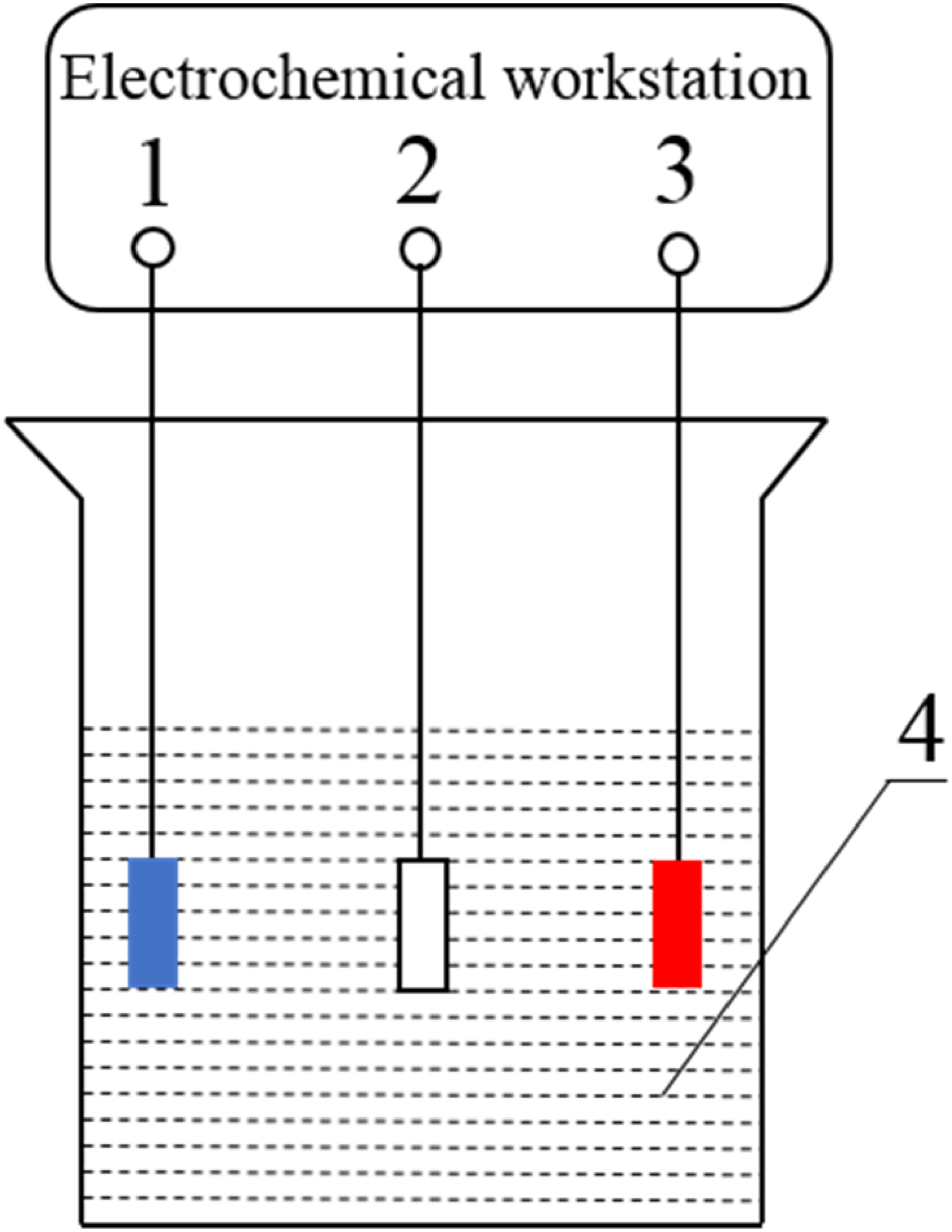
Schematic diagram of electrochemical workstation 1-working electrode; 2-reference electrode; 3-counter electrode; 4-electrolyte solution.
Results and discussion
Microstructure and mechanical properties of as-cast HHCCI
Effect of N content on as-cast microstructure of HHCCI
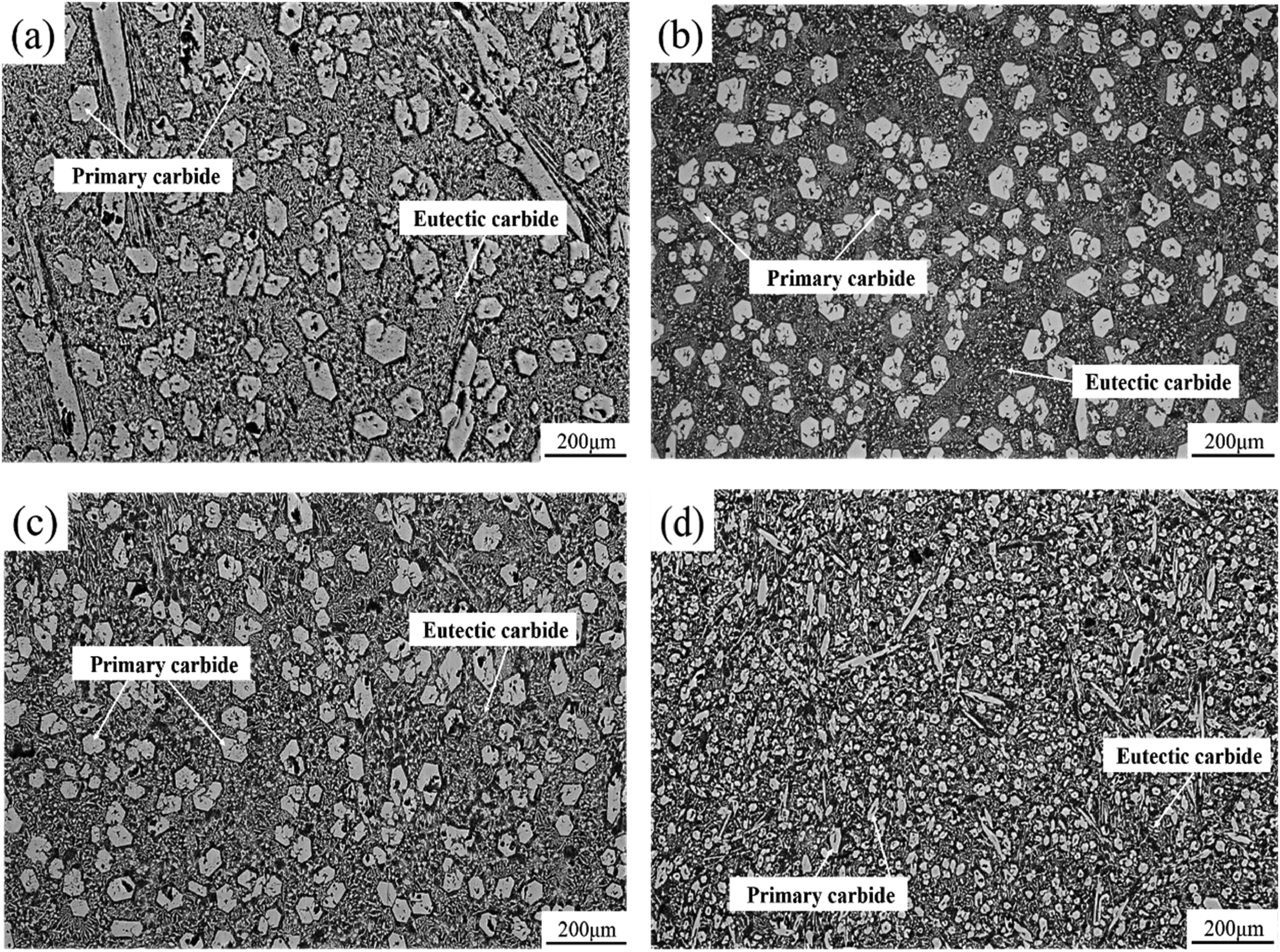
Figure 3 shows the metallographic photos of HHCCI as-cast with different N contents. It can be seen from the picture that the as-cast sample is mainly composed of M7C3 primary carbides, eutectic carbides and metal matrix. The primary carbides are hexagonal blocks, and the eutectic carbides are distributed around the primary carbides in chrysanthemum shape. With the increase of N content, it can be seen that the primary carbides are obviously refined, and the eutectic carbides do not change significantly. The volume fraction of carbides and the equivalent diameter of primary carbides are calculated by Image Pro Plus software, the statistical results are shown in Figure 4. The volume fraction of carbides is mainly determined by Cr and C, since the contents of Cr and C in the samples are the same, the volume fraction of carbides does not change significantly after adding different contents of N, but the equivalent diameter of primary carbides decreases greatly. Without N addition, the equivalent diameter of primary carbides is 61 μm. When 0.15 wt.% N is added, the equivalent diameter of primary carbides decreases to 46 μm and the size decreases by 32%. When the N content continues to increase to 0.3 wt.% N, the primary carbides are not further refined, and the N content continues to increase to 0.45 wt.%, the equivalent diameter of the primary carbides is 30 μm, a size reduction of 103%. According to the literature, 15 in the generation of M7C3 carbides, N atoms can replace some of the C atoms to bond with Fe or Cr atoms, due to the larger bonding force, N atoms can lead to partial lattice distortion of carbides, and with the increase of N content, crystal defects such as dislocations and layer dislocations also increase, and these defects lead to the change of carbide morphology, and when the N content increases to the critical content, the lattice distortion is too large to exist stably, so that the growth of carbides is interrupted, and therefore the carbides are refined.
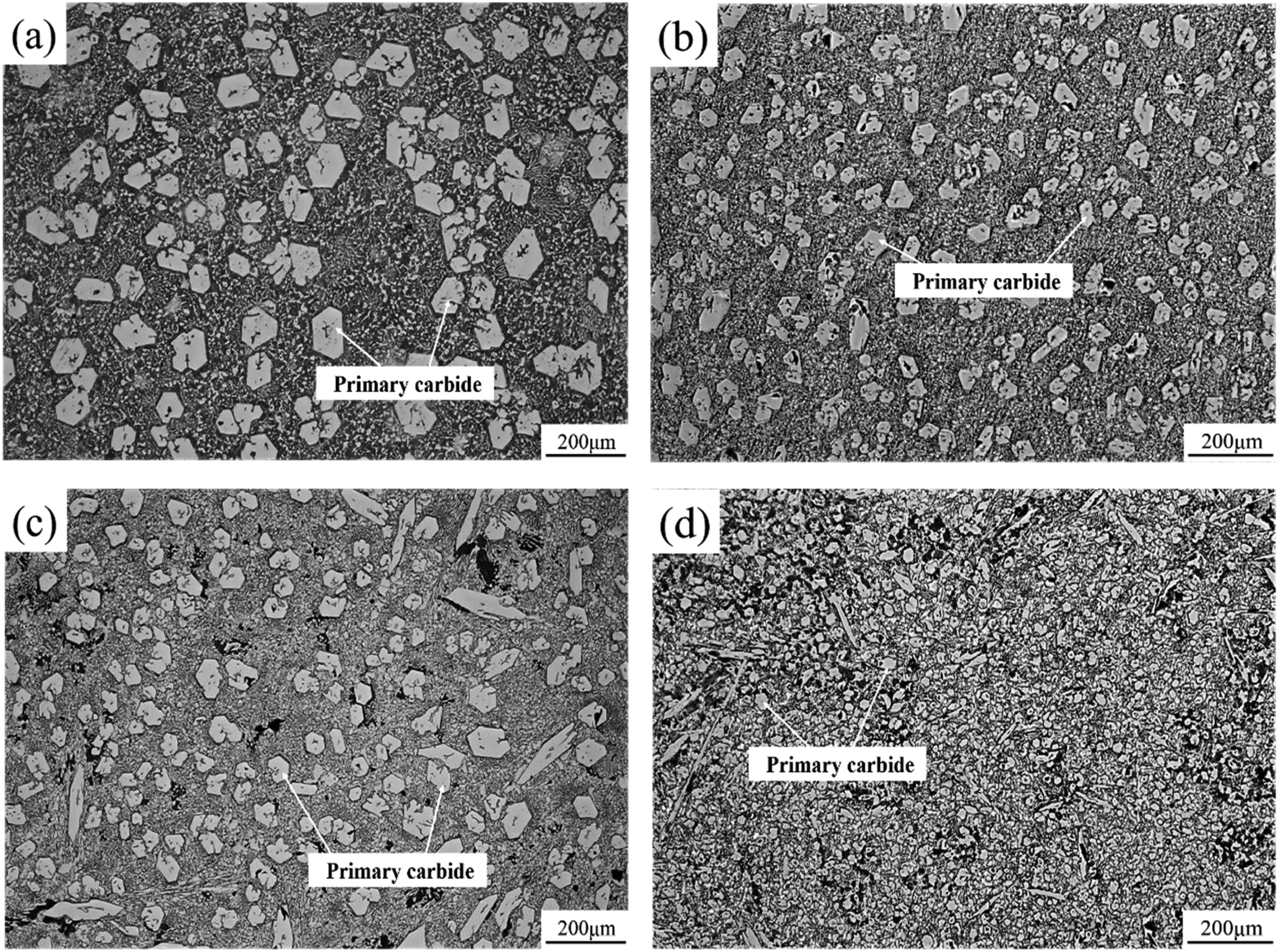
Metallographs of HHCCI with different N contents in the as-cast state: (a) 0 wt.% N; (b) 0.15 wt.% N; (c) 0.3 wt.% N; (d) 0.45 wt.% N.
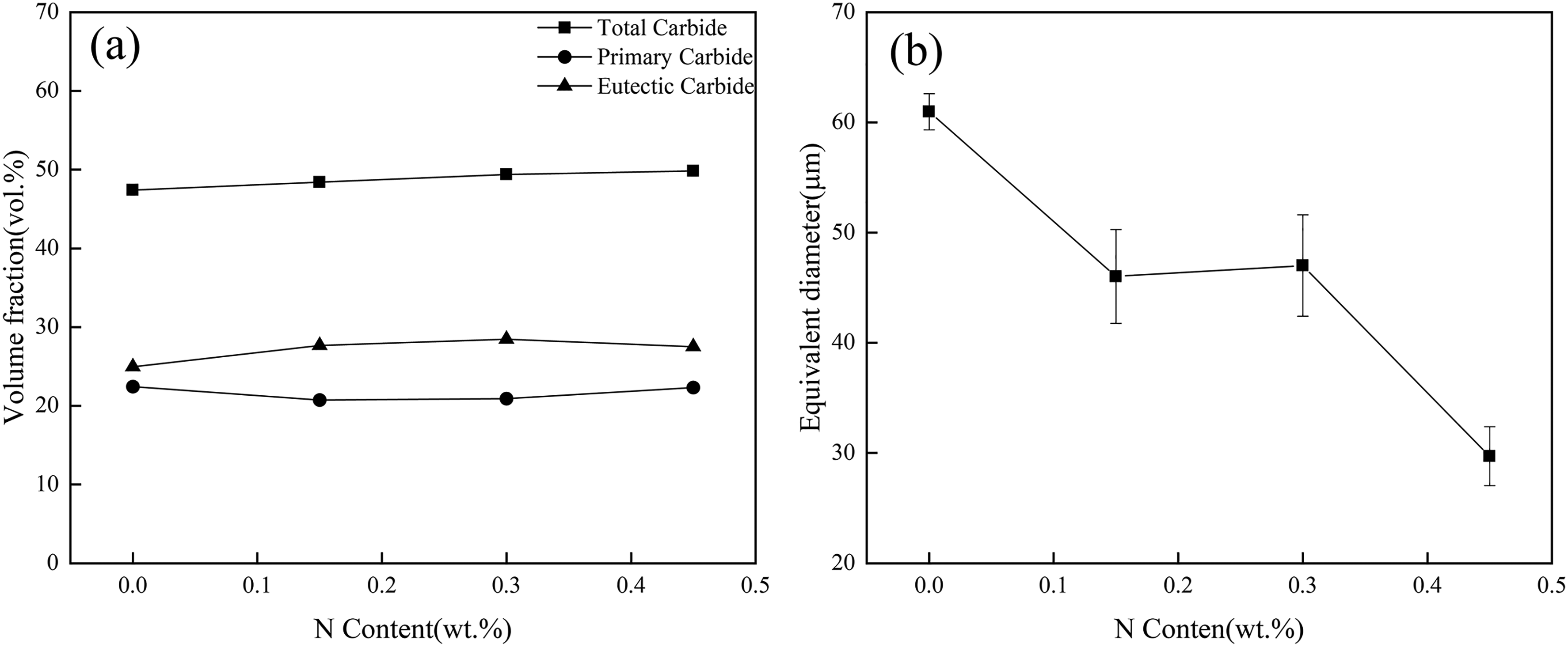
Effect of N content on the volume fraction of carbides (a) and the equivalent diameter of primary carbides (b) in as-cast HHCCI.
To further observe the effect of N content on the microstructure of HHCCI, the specimens are observed by SEM, and the results are shown in Figure 5. It can be seen that there is no particle precipitation around the eutectic carbide without N element. When the N content increases to 0.15 wt.%, it can be seen that around the eutectic carbides, fine particles are precipitated, and close to the eutectic carbide region, these fine particles have been agglomerated together, while in the region far from the eutectic carbides, the Cr atoms are too late to diffuse, resulting in less Cr element content in this region and fewer particles are generated. As the N content continues to increase to 0.3 wt.%, it can be seen that the previously generated fine particles have been connected together and distributed in lamellar form around the primary carbides and eutectic carbides, and as the N content continues to increase to 0.45 wt.%, it can be seen that these lamellar microstructures not only increase, but also coarsen significantly. According to the literature, these lamellar structures are Cr2N.18,19 In order to study the precipitation sequence of Cr2N and carbides during solidification, Jmat-Pro software is used for simulation, and the simulation results are shown in Figure 6. It can be seen from the diagram that the precipitation temperature of M2(C, N) gradually increases with the increase of N content. After adding 0.3 wt.%N, although the content of N increased, the order of precipitated phases did not change. The precipitated M2(C, N) is still after the primary carbide, resulting in no further refinement of the primary carbide. After adding 0.45 wt.%N, a part of M2(C, N) will be precipitated first. The precipitated M2(C, N) can not only grow around the primary carbides and inhibit the growth of the primary carbides, but also consume the Cr atoms in the liquid phase to further refine the primary carbides. This is also the reason why the primary carbides are not further refined when the N content is 0.3 wt.%, while the N content is 0.45 wt.%, the primary carbides can be further refined.
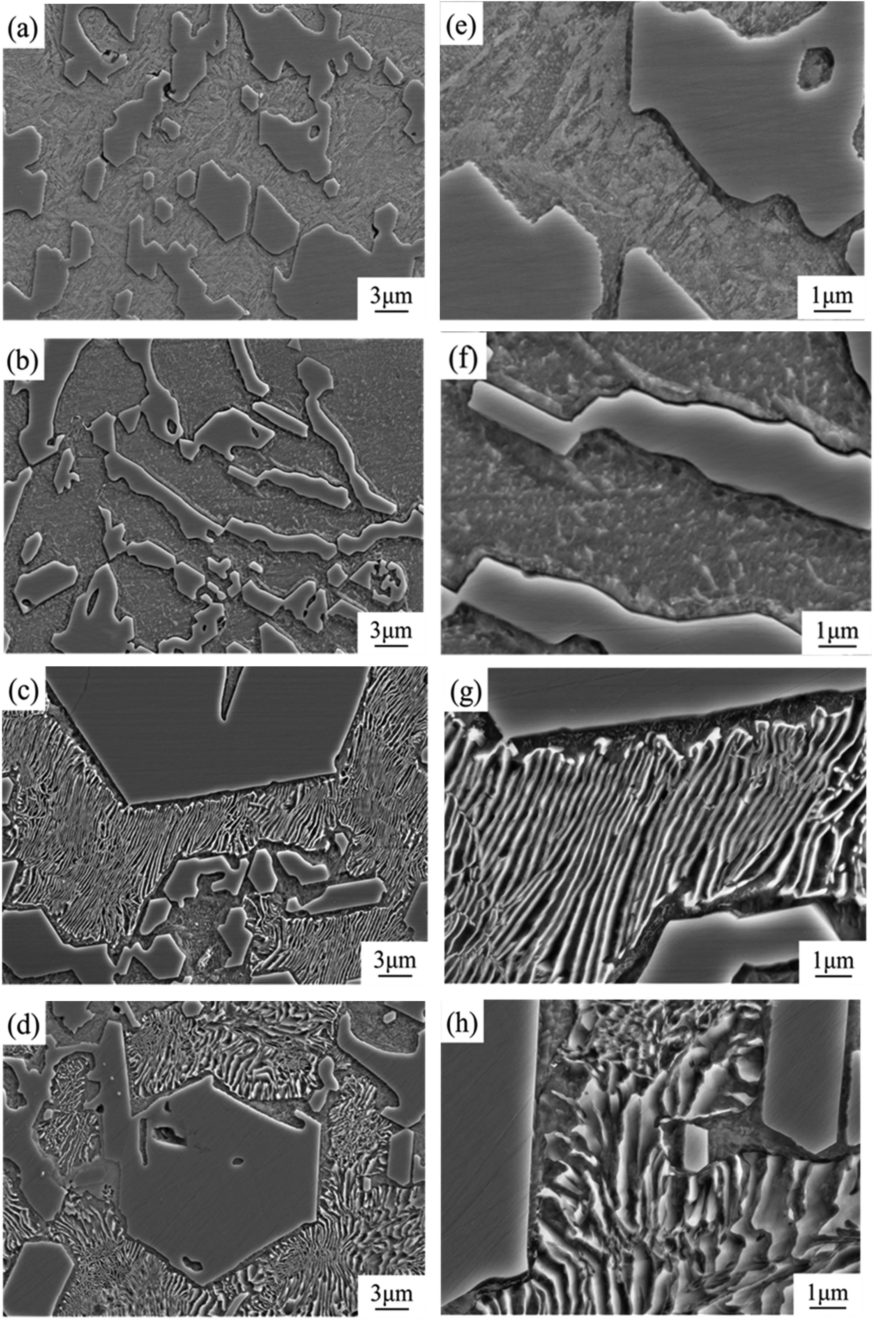
SEM images of HHCCI with different N contents in as-cast state: (a, e) 0 wt.% N; (b, f) 0.15 wt.% N; (c, g) 0.3 wt.% N; (d, h) 0.45 wt.% N.
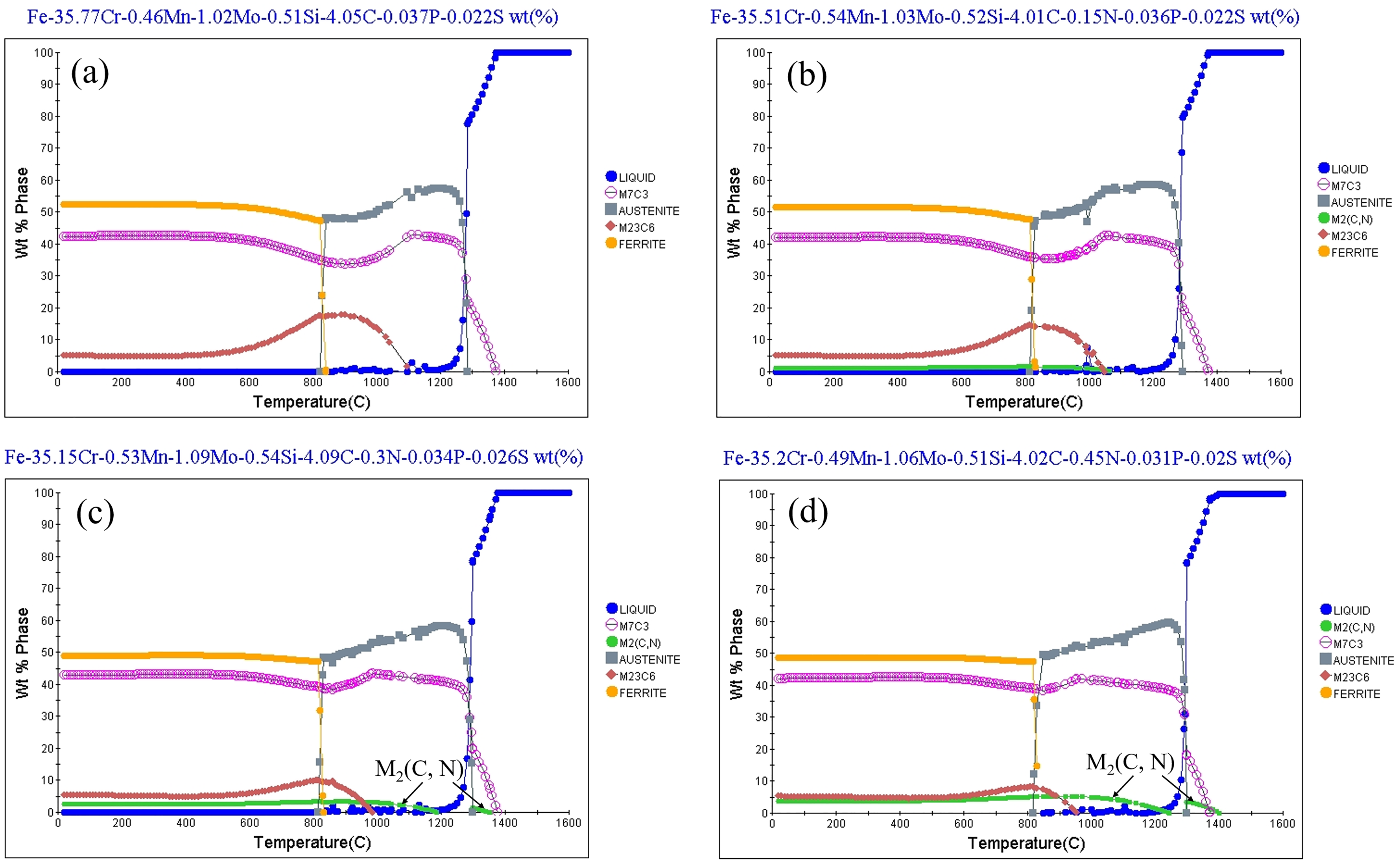
Simulation of the phases at different N contents during solidification of HHCCI: (a) 0 wt.% N; (b) 0.15 wt.% N; (c) 0.3 wt.% N; (d) 0.45 wt.% N.
For this aspect of N refinement of grains, previous studies have found that the generated nitrides can act as nucleation sites to refine grains by adding Ti and Nb strong carbon-nitride-forming elements.9,10 In contrast, these strong nitride-forming elements were not added in this article, and N was found to refine the primary carbides, indicating that N is not dominant as a heterogeneous nucleation mass to refine the grains. N refinement of grains is also mainly influenced by lattice distortion and precipitated phases, and the addition of 0.15 wt.%N resulted in the refinement of incipient carbides in HHCCI, mainly attributed to the replacement of C elements by N elements to produce lattice distortion, which increased the crystal defects and refined the carbides, which is in agreement with the results of previous studies. 15 Continuing to increase the N content, it was found that M2(C, N) would precipitate before the primary carbides M7C3 and surround the primary carbide, limiting the growth of the primary carbides, thus enabling further grain refinement.
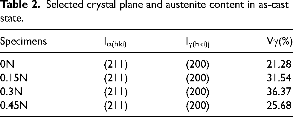
In order to analyse, the distribution of elements in HHCCI, SEM is used for surface scanning, and the scanning results are shown in Figure 7. From the energy spectrum scanning results, Fe elements are distributed in large amounts in the matrix, Cr and C elements are mainly distributed in the primary carbides and eutectic carbides, and N elements are mainly enriched in the lamellar organisation. Figure 8 shows the XRD spectrum of as-cast HHCCI with different N contents. It can be seen that the as-cast HHCCI phases are mainly composed of M7C3 carbides, austenite, martensite and Cr2N, the phase composition of the sample was determined by comparing the XRD spectrum of the sample with the standard spectrum. Austenite (52–0512), martensite (44–1290), M7C3 (05–0720) and Cr2N (79–2159) PDF cards were used in the experiment, and the content of austenite is calculated by Formula (2) as shown in Table 2. It can be seen from the figure that the addition of N to HHCCI does not change the type of matrix and carbides, but a new phase Cr2N is formed. With the increase of N content, it can be seen that the diffraction peak of austenite is obviously enhanced, indicating that the austenite content is significantly higher, indicating that N can significantly stabilise austenite, when the N content is 0.45 wt.%, the austenite content decreases, the reason is that the formation of lamellar Cr2N will also consume part of the N content in the matrix, resulting in a decrease in the N content dissolved in the matrix, which reduces the ability of N to stabilise austenite. From Figure 8, it also can be seen that after adding N, the diffraction peak position of the austenite phase moves from 43.51° to 43.31°, indicating that the N element is dissolved in the matrix, causing the lattice distortion. According to the Bragg equation, 2dsinθ = λ, due to the lattice distortion, the crystal plane spacing d increases and the diffraction angle decreases. Therefore, the diffraction peak position of the austenite will shift to the left.
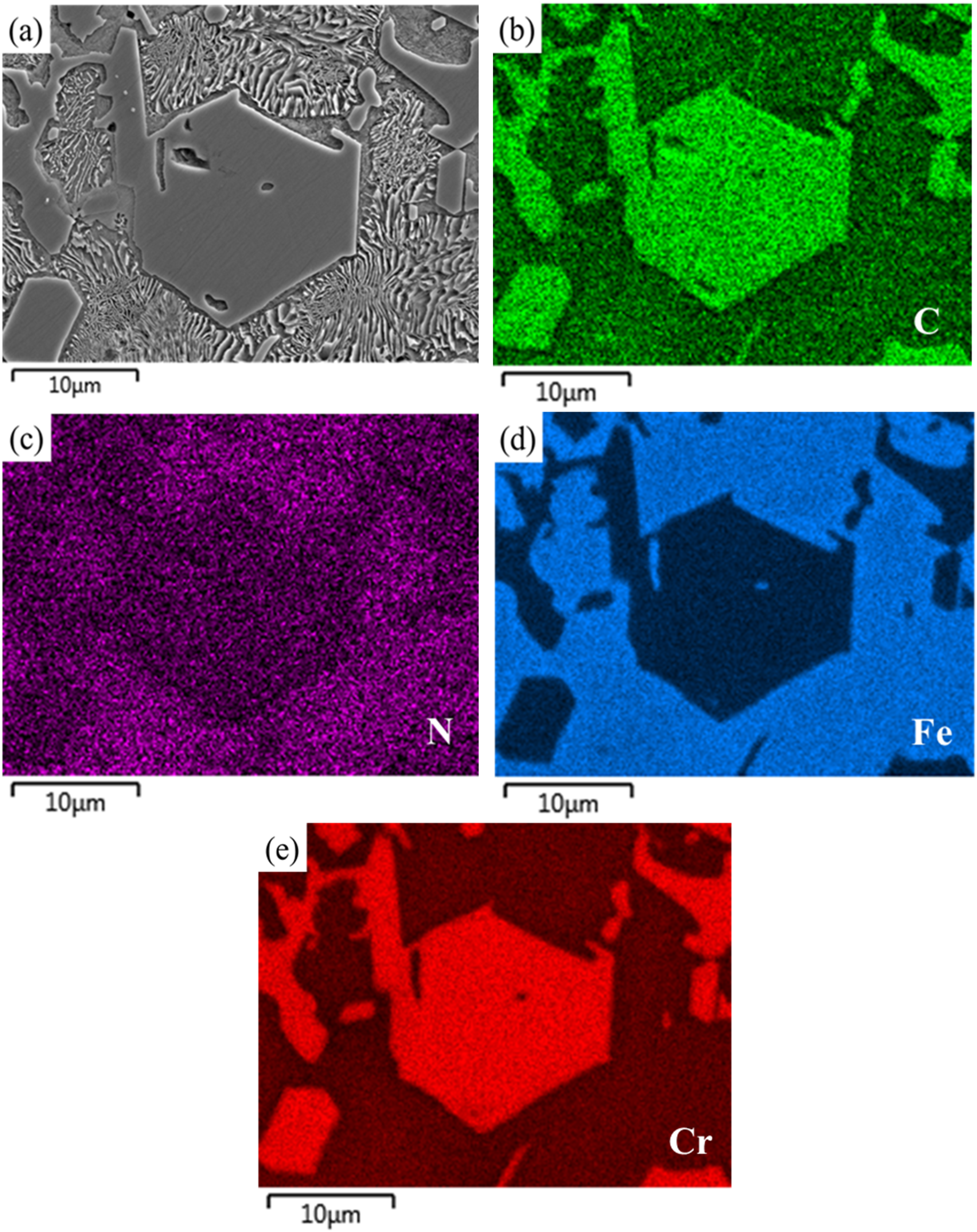
EDS analysis of as-cast 0.45 wt.% N HHCCI: (a) SEM image; (b–e) The distribution maps of C, N, Fe and Cr.
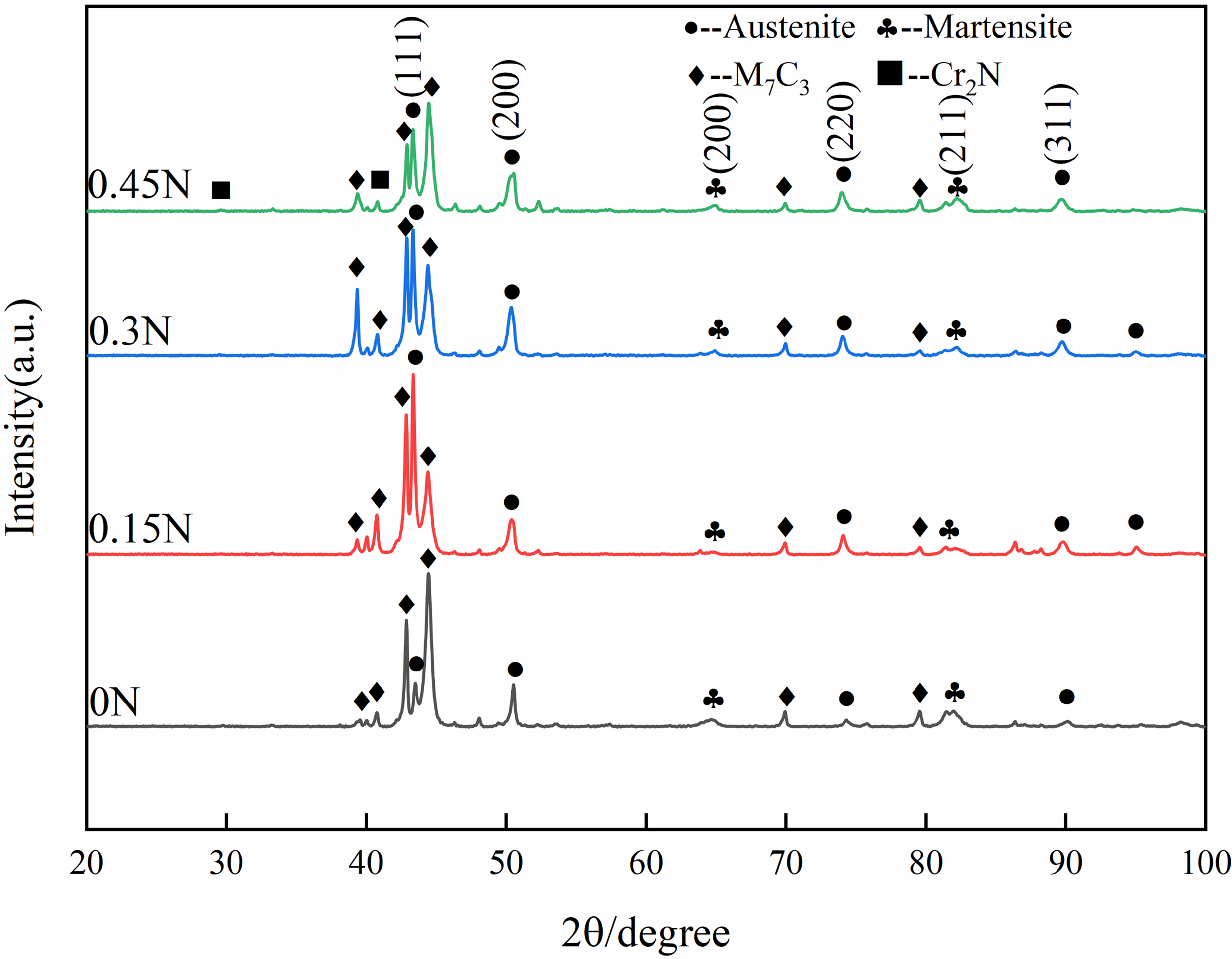
XRD spectrums of as-cast HHCCI with different N contents.
Selected crystal plane and austenite content in as-cast state.
Effect of N content on hardness of as-cast HHCCI
Figure 9(a) shows the effect of N content on the microhardness of as-cast HHCCI. The addition of N element increases the hardness of the matrix due to its smaller atomic radius (0.071 mm) than C (0.077 mm) and Fe (0.125 mm) atoms, which can be dissolved in the matrix metal as interstitial atoms and cause lattice distortion. When N is not added, the microhardness of as-cast HHCCI is the lowest, which is 493 ± 40 HV. With the increase of N content, the hardness of as-cast HHCCI matrix increases first and then decreases. The microhardness of as-cast HHCCI with 0.3 wt.% N content is 537 ± 21 HV. This is because N has the effect of expanding the austenite phase region. When the N content is 0.3 wt.%, the HHCCI austenite content is the highest, which reduces the martensite content and thus reduces the microhardness of the matrix. The content of N has no obvious effect on the microhardness of carbides. This is because the addition of N does not change the type of primary carbides and eutectic carbides. The hardness of M7C3 primary carbides remains between 1400 and 1600 HV, which is consistent with the literature. 20 Figure 9(b) shows the effect of N content on the macrohardness of as-cast HHCCI. The hardness of HHCCI is 54.7 HRC without N. After adding N, the hardness of HHCCI increases first, then decreases, and finally increases again. When the N content is 0.15 wt.% and 0.45 wt.%, the hardness of as-cast HHCCI is 56.8 HRC and 56.9 HRC, respectively.
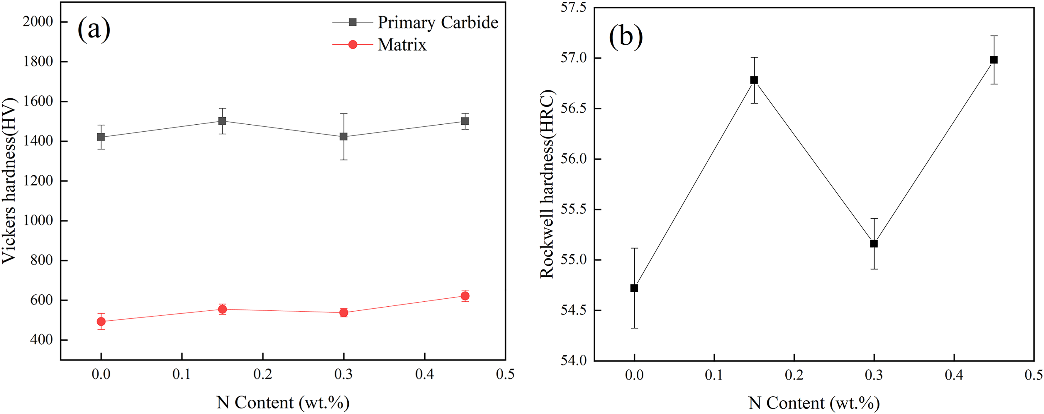
Effect of different N contents on microhardness (a) and macrohardness (b) of as-cast HHCCI.
The hardness of HHCCI is mainly determined by the carbide hardness, volume fraction and matrix type, 21 since the volume fraction of HHCCI carbides in the test was approximately equal (about 48%), then the overall hardness of the studied HHCCI depends on the carbides morphology and matrix. When N is not added, the macro-hardness of HHCCI is the lowest, because the primary carbides are too coarse and the microhardness of the matrix is low. When the N content is 0.15 wt.%, the hardness increases due to the refinement of primary carbides and the precipitation of dispersed fine granular Cr2N around carbides. When the N content increases to 0.3 wt.%, the hardness of the matrix decreases due to its high austenite content, and the precipitation of Cr2N is no longer a dispersed distribution of particles, but a lamellar distribution, and the primary carbides are not further refined, resulting in a decrease in hardness. When the N content continues to increase to 0.45 wt.%, the hardness increases again. Although there are also lamellar Cr2N in HHCCI, due to the further refinement of the primary carbides, and the strength of the matrix is also further improved, these favourable factors can make a greater contribution to the improvement of macrohardness, thereby leading to an increase in macrohardness.
Effect of N content on corrosion resistance of as-cast HHCCI
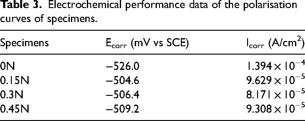
The dynamic potential polarisation curve of HHCCI in acidic solution with PH = 1 is shown in Figure 10, and the corrosion potential Ecorr is extrapolated in the Tafel region to obtain the corrosion current density Icorr, and the results are shown in Table 3. From the kinetic point of view, the greater the corrosion current density, the faster the corrosion rate of the material and the worse the corrosion resistance of the material. According to the corrosion current density of Table 3, in the acidic corrosive solution of PH = 1, the corrosion current density after adding N element is one order of magnitude lower than that of HHCCI without N element, indicating that its corrosion resistance has been improved, which is in accord with previous investigations.11,13 When the N content is 0.3 wt.%, the corrosion current density is the lowest and the corrosion resistance is the best. After the addition of N element, N can be dissolved into the matrix, increasing the electrode potential of the matrix, and the dissolved N in the matrix consumes H+ in the pores or gaps of HHCCI after acid corrosion to form NH+, which reduces the PH value of the corrosion solution, 22 thereby improving the corrosion resistance of HHCCI. When the N content increases to 0.3 wt.%, HHCCI has the highest austenite content. Compared with the martensite matrix, the electrode potential of the austenite matrix is high, and the potential difference between the austenite matrix and the carbides is small, resulting in the best corrosion resistance. When the N content continues to increase to 0.45 wt.%, due to the high N content, more Cr atoms will be consumed to generate Cr2N, which will lead to a Cr-poor area near Cr2N, making the matrix more prone to corrosion, resulting in a decrease in corrosion resistance. 23
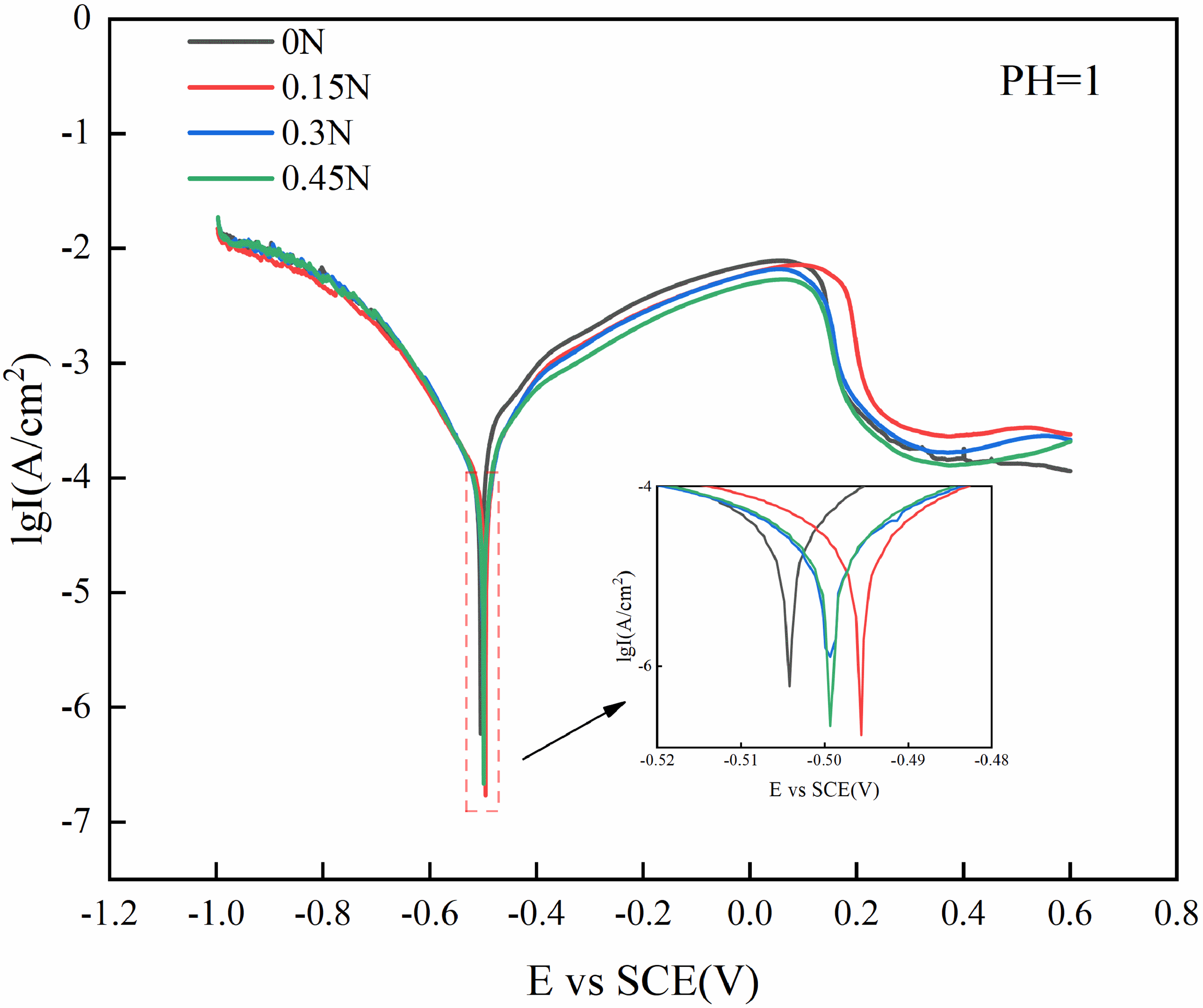
Dynamic potential polarisation curve of as-cast HHCCI.
Electrochemical performance data of the polarisation curves of specimens.
Microstructure and mechanical properties of HHCCI after heat treatment
Effect of N content on microstructure of HHCCI after quenching
Figure 11 shows the microstructure of HHCCI after holding at 1000 °C for 1 h. Compared with the as-cast state, the size and shape of primary carbides do not change significantly, indicating that quenching has no significant effect on primary carbides. The boundary of eutectic carbides is clearer and distributed around primary carbides in a broken network. Figure 12 shows the precipitation of secondary carbides in the eutectic austenite region between primary carbides and eutectic carbides. The morphology of the precipitated secondary carbides is mostly blocky, with a size of about 340 nm, and a small amount of short rod-like secondary carbides are also precipitated, with a size of about 190 nm, and with the increase of N content, it can be seen that the distribution of secondary carbides is more uniform. Figure 13 is the secondary carbides point scan diagram of 0.45 wt.%N HHCCI with different morphologies under quenching state. Table 4 is the results of EDS point scan. It can be seen from the table that the (Cr + Fe): C≈23:6 in the short rod-like secondary carbides, which are judged to be of M23C6 type. There are two types of bulk secondary carbides, one without N, and its (Cr + Fe): C≈7:3, which is M7C3 type, the other contains N, may be Cr2N. It will be further judged by electron diffraction patterns of transmission electron microscopy, and a small amount of N is also detected in the matrix, as shown in spectrum 3.
Metallographs of HHCCI with different N contents after quenching: (a) 0 wt.% N; (b) 0.15 wt.% N; (c) 0.3 wt.% N; (d) 0.45 wt.% N.
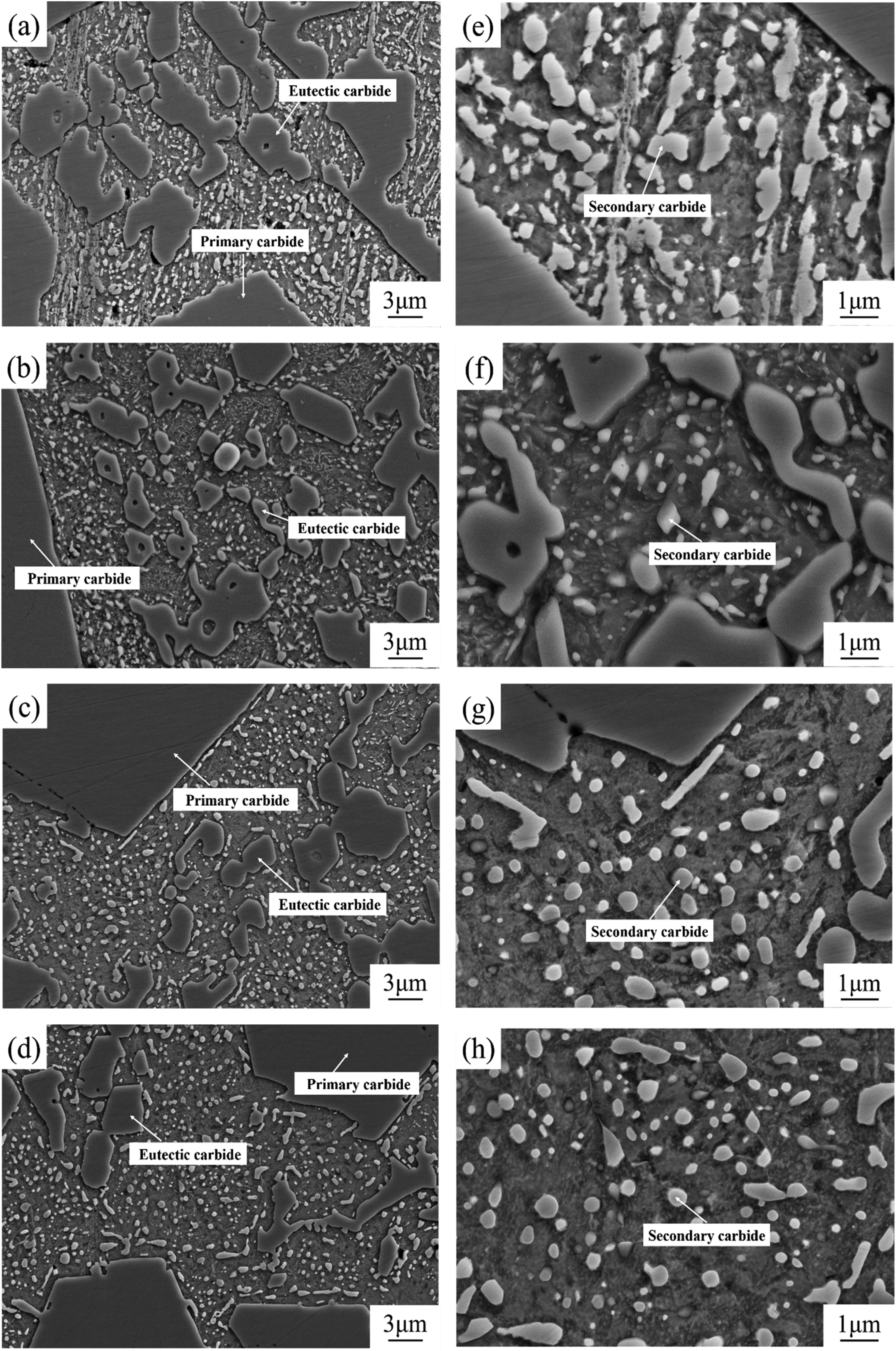
SEM images of HHCCI with different N contents after quenching: (a, e) 0 wt.% N; (b, f) 0.15 wt.% N; (c, g) 0.3 wt.% N; (d, h) 0.45 wt.% N
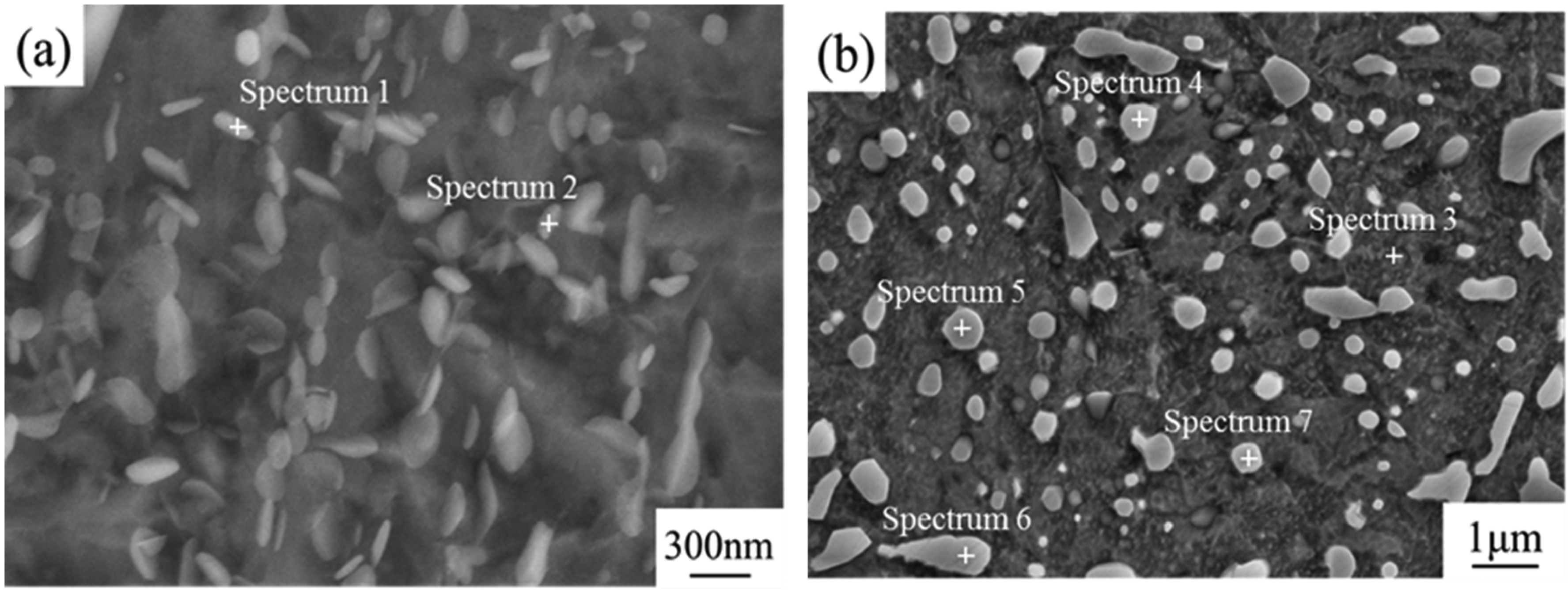
Spot scan position map of secondary carbides with different morphologies of 0.45 wt.% N HHCCI after quenching: (a) short rod-like; (b) block.
EDS point analysis of secondary carbides with different morphologies of 0.45 wt. % HHCCI in quenched state (at.%).
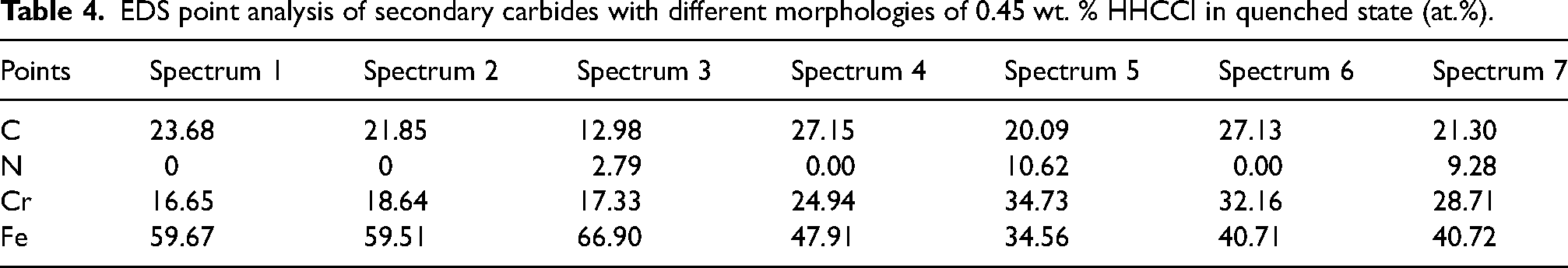
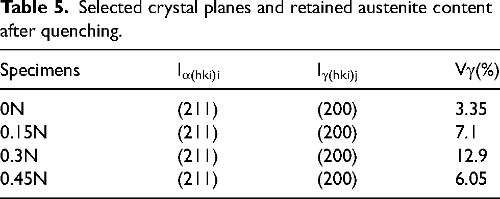
Figure 14 shows the XRD spectrum of HHCCI after quenching. It can be seen from the diagram that HHCCI phases after quenching are mainly composed of M7C3 type carbides, M23C6 type carbides, Cr2N, martensite and retained austenite, which is consistent with the type of secondary carbides determined by point scanning as described above, and the content of retained austenite in HHCCI after quenching is calculated, as shown in Table 5, compared with the as-cast HHCCI austenite content (Table 2), the HHCCI retained austenite content after heat treatment at 1000 °C is significantly reduced. This is because during the heat treatment process, a large number of secondary carbides are precipitated from the austenite matrix, these secondary carbides consume a large amount of Cr and C elements in the matrix, which reduces the stability of the austenite and transforms into martensite during the subsequent cooling process. 24
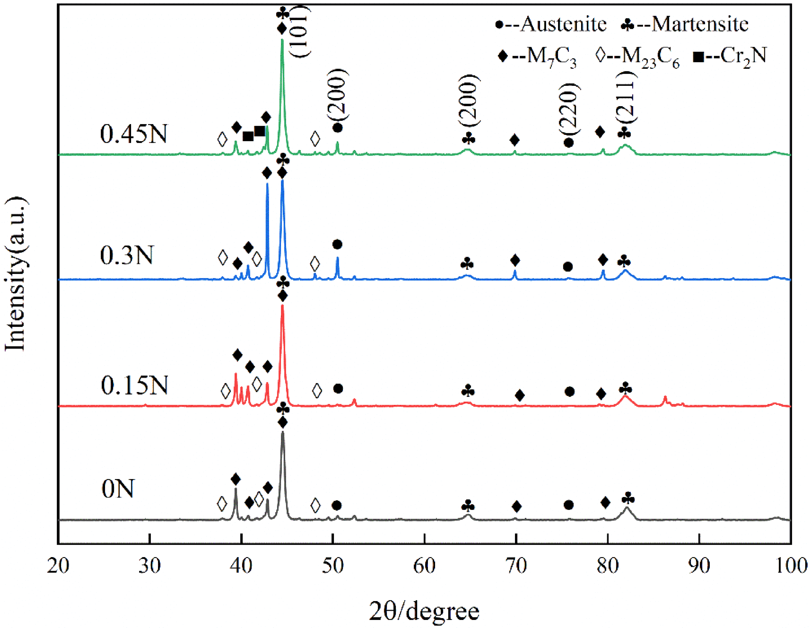
XRD spectrums of HHCCI with different N content after quenching.
Selected crystal planes and retained austenite content after quenching.
Effect of N content on hardness and wear resistance of heat-treated HHCCI
Figure 15(a) shows the microhardness of HHCCI after heat treatment at 1000 °C. Compared with the as-cast state (Figure 9a), the microhardness of the matrix after heat treatment is significantly improved. This is because the matrix of as-cast HHCCI is mainly austenite (300–600 HV) and the hardness is low. After quenching, the austenite transforms into martensite (500–1000 HV), which makes the microhardness of HHCCI increase significantly. When N is not added, the hardness of the HHCCI matrix is 652 ± 38 HV. After adding N, the microhardness of the matrix increases first and then decreases, which is consistent with the change trend of the matrix hardness in the as-cast state. When the N content is 0.3 wt.%, the hardness of the matrix is 756 ± 24 HV. This is because the HHCCI has a high content of austenite in the as-cast state. After quenching, there is still a high content of austenite that does not transform into martensite, resulting in a decrease in its hardness. Figure 15(b) shows the macrohardness of HHCCI after quenching, the macrohardness of HHCCI after heat treatment mainly depends on the hardness of carbides and matrix and the volume fraction of secondary carbides, most of the austenite is transformed into hard martensite, and a large number of dispersed secondary carbides are precipitated, leading to a significant increase in the hardness. The trend of hardness change after the addition of N is the same as in the as-cast state, The macrohardness of 0.15 wt.%N and 0.45 wt.%N is 65.5 HRC and 65.6 HRC, respectively, with little difference between them.
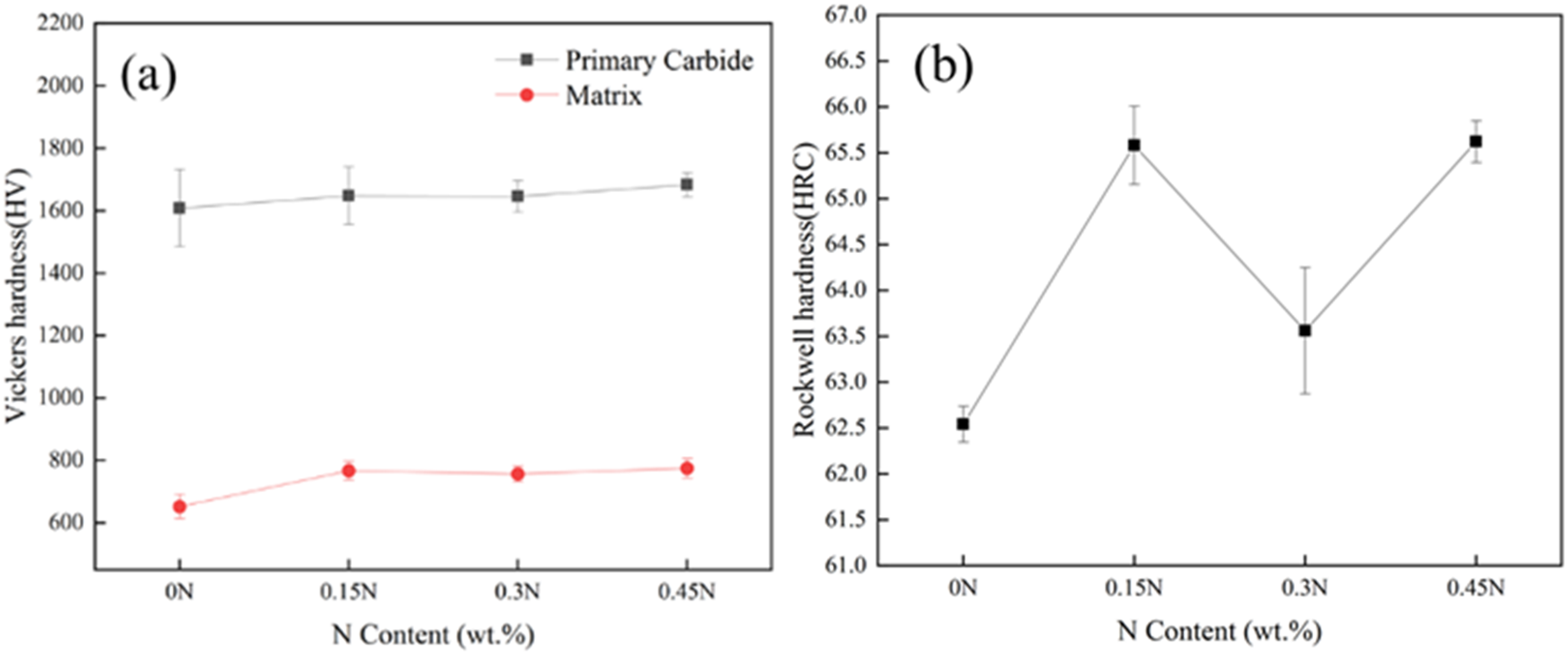
Effects of different N contents on microhardness (a) and macrohardness (b) of quenched HHCCI.
Since the specimens were quenched by a large internal stress, which would lead to specimen cracking, the quenched specimens were tempered at 250 °C × 4 h before the wear resistance test. It can be seen from Figure 16 that the amount of wear increases gradually with the increase of wear time, the weight loss of HHCCI without N element is 11.84 mg after 2 h, after adding N element, the weight loss of HHCCI decreases, where the weight loss of HHCCI with 0.15 wt.%N is the smallest, 7.52 mg, and the wear resistance is the best, which is 1.57 times of that without N. With the increase of N content, the wear resistance of HHCCI decreases gradually, when the N content increases to 0.45 wt.%, the wear resistance of HHCCI is the worst. Although the hardness of 0.45 wt.% sample is the highest, the wear resistance is not only related to the hardness, but also related to the matrix properties and the composition, distribution, content and size of the second phase. 20 The addition of N element improves the macrohardness of HHCCI and the strength of the matrix, and the generated Cr2N is precipitated in a dispersed granular form, which improves the wear resistance of HHCCI. When the N content continues to increase, these Cr2N particles will be connected together to form lamellar Cr2N, which is unfavourable for wear resistance, with the increase of N content, lamellar Cr2N will become coarser, which greatly reduces the wear resistance of HHCCI. Under the interaction of these factors, the wear resistance of 0.15 wt. % sample is the best.
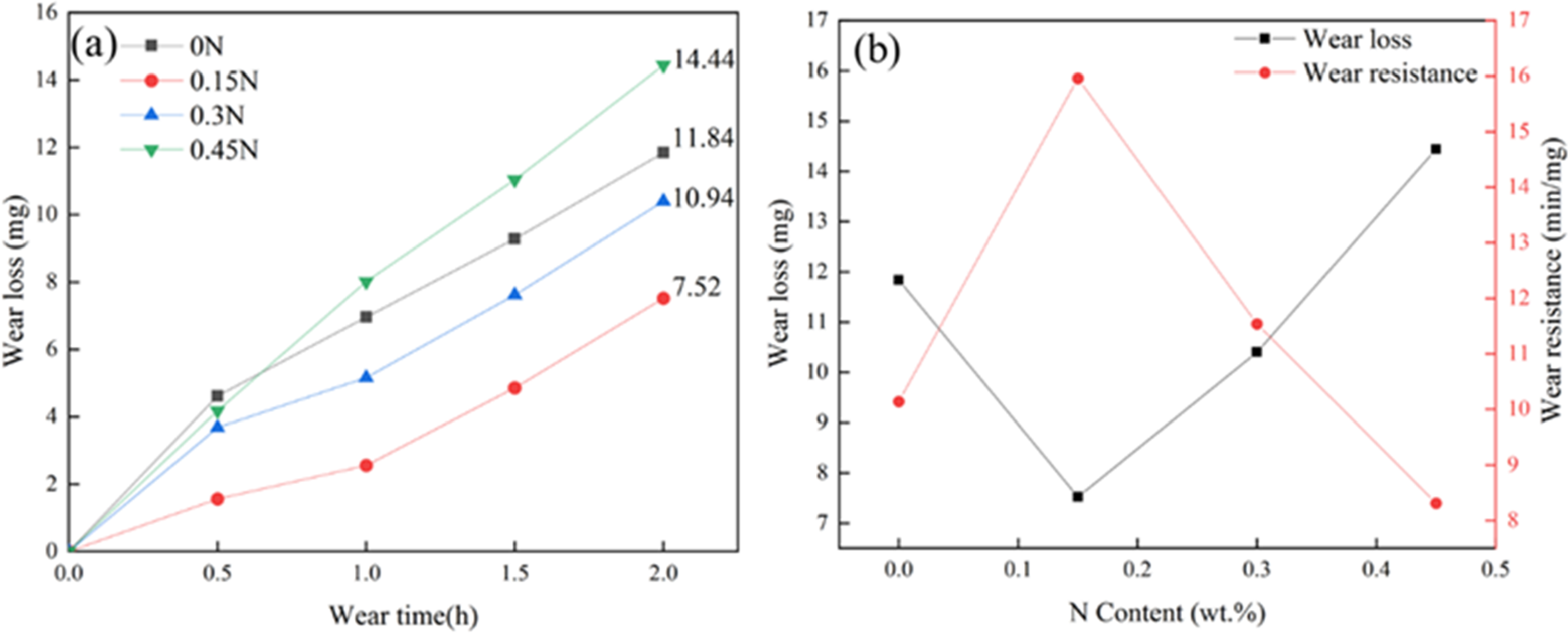
Effect of different N contents on wear (a) and wear resistance (b) of tempered HHCCI.
Figure 17 shows the surface morphology of HHCCI after wear. It can be seen that the main morphologies of HHCCI after wear are craters formed by carbides spalling, wear debris attached to the surface of the material and plough. It shows that the wear mechanism is fatigue wear, abrasive wear and adhesive wear. When the sliding friction occurs between the HHCCI surface and the wear ring, due to the small wear area and the long wear time, the matrix structure with low hardness is worn out first during the wear process, resulting in the leakage of coarse carbides in the wear environment. After many friction cycles, carbides are peeled off under the action of shear force to form spalling craters. At the same time, the hard carbides that fall off are embedded into the surface of the matrix under the action of pressure, and the plough grooves are formed on the surface of the matrix during the subsequent sliding process. During the wear process, the surface of the sample and the grinding ring are in direct contact, under the action of friction, the temperature at the interface increases continuously, which leads to the welding of the contact parts of the material. As the sliding proceeds, the contact parts are separated and transferred to the surface of the grinding ring to form wear debris. 25
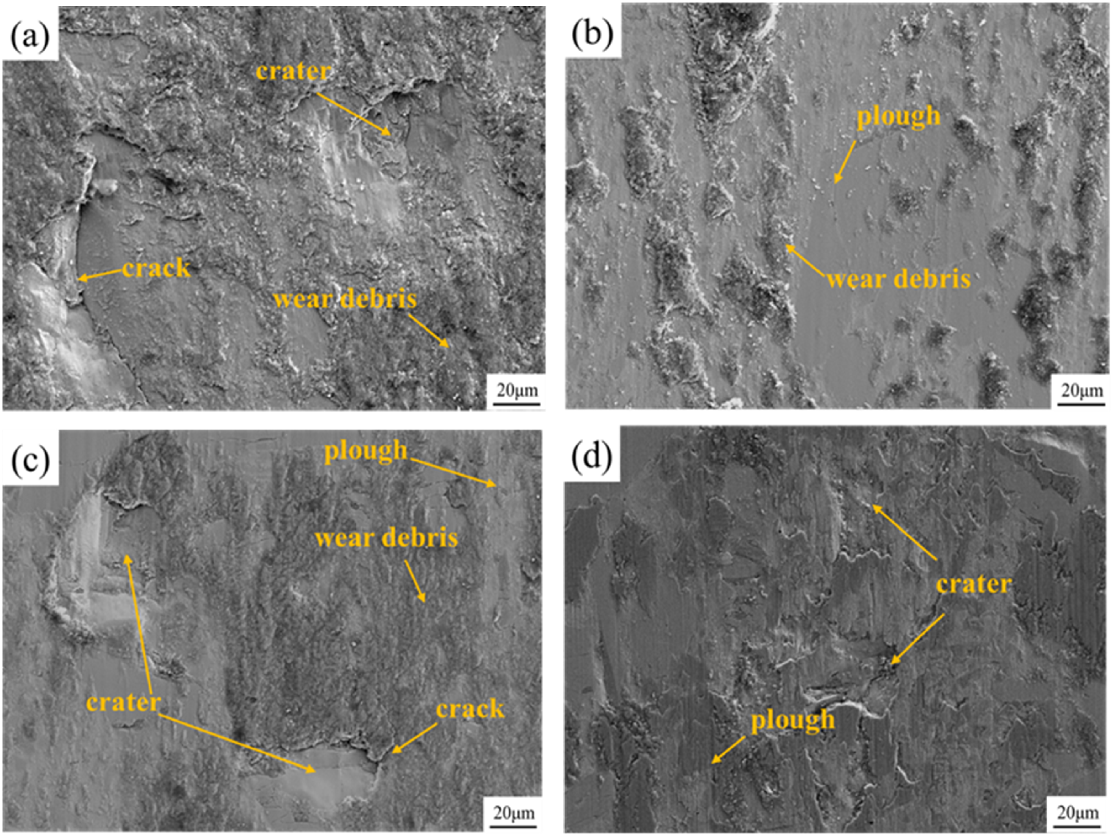
SEM images of the worn surface of tempered HHCCI with different N contents (a) 0 wt.% N; (b) 0.15 wt.% N; (c) 0.3 wt.% N; (d) 0.45 wt.% N.
When N is not added, the surface of the specimen after HHCCI wear is mainly wear debris and craters formed by carbide spalling, and the wear is mainly fatigue wear and adhesive wear, and it is also found that there are longer cracks at the carbide edge, which is due to the stress concentration under the action of shear during the wear process, and the plastic deformation in the sliding direction leads to the rapid expansion of cracks, resulting in carbide spalling and the formation of spalling craters. After adding 0.15 wt.% N, HHCCI shows shallow plough and wear debris, and its wear is mainly dominated by abrasive and adhesive wear, and the carbides do not fracture, indicating that the wear resistance is improved. When the N content increases to 0.3 wt.%, the number of HHCCI spalling craters increases and the wear resistance decreases. When the N content increases to 0.45 wt.%, HHCCI not only has a large number of carbides fracture and formation of spalling craters, but also finds an increase in the depth of the plough grooves, and the wear is dominated by fatigue wear and abrasive wear, showing the worst wear resistance.
Conclusions
This article investigates the effects of different N contents on the microstructure and properties of HHCCI, and the main results are summarised as follows:
After adding N to HHCCI, the primary carbides are obviously refined, and the austenite content is significantly increased. The as-cast HHCCI microstructure is mainly composed of M7C3 carbides, Cr2N, austenite and martensite. With the increase of N content, Cr2N gradually changes from dispersed granular to coarse lamellar structure. After quenching at 1000 °C, there are short rod-like and block secondary carbides precipitated. With the increase of N content, the hardness of HHCCI first increases, then decreases, and finally increases. The hardness of the as-cast sample without N addition is 54.7 HRC, and the hardness increases to 56.8 HRC after adding 0.15 wt.% N. After quenching at 1000 °C, the hardness of the sample shows the same trend, from 62.5 HRC to 65.6 HRC. The corrosion resistance of HHCCI increases with the increase of N content. The 0.3 wt.% N specimen shows the best corrosion resistance. The addition of N can increase the electrode potential of the matrix, which lead to enhance corrosion resistance, but the excessively high content of N lead to the generation of more Cr2N, resulting in Cr-poor zones in the matrix and making the corrosion resistance lower. With the increase of N content, the wear weight loss of HHCCI decreases and the wear resistance is improved. When the N content is 0.15 wt.%, the wear weight loss of HHCCI is the least and the wear resistance is the best. When the N content continues to increase, the wear resistance of HHCCI decreases.
Footnotes
Declaration of conflicting interests
The authors declared no potential conflicts of interest with respect to the research, authorship, and/or publication of this article.
Funding
The authors disclosed receipt of the following financial support for the research, authorship, and/or publication of this article: This work was supported from National Natural Science Foundation of China (52075010) and Hebei Science and Technology Major Project (22281005Z).