
Abstract
Linear quadratic Gaussian optimal control is one of the techniques used for active noise control. In practical implementation of this technique, one of the key difficulties faced is the estimation of the states of the plant. A state observer that accurately estimates these states can be used in this regard. Studies reported make use of analytically or experimentally derived models to build observers. This paper proposes a method for active noise control in the framework of active structural-acoustic control incorporating system identification for the development of the linear quadratic Gaussian controller. Kalman filter is used as a stochastic state observer of the plant states. System identification is carried out using modal testing and finite element model updating to obtain an accurate model of the plant for building up the Kalman filter. The objective of the proposed method is to actively reduce the noise inside the cavity due to disturbances acting on the cavity structure. The active control is achieved by controlling the structural vibrations by taking into account the degree of coupling between the various structural and the acoustic modes. The effectiveness of the proposed method is evaluated experimentally on a 3D rectangular box cavity with a flexible plate.
Keywords
Introduction
Active noise control is a technique of reducing the primary noise by actively cancelling it with the help of secondary actuators. These techniques are of interest in reducing low frequency noise where passive techniques are not so effective. One of the important potential applications of active noise control is in controlling noise in enclosed spaces such as in cavities encountered in automotive, aerospace and other transportation equipment.
A predominant component of interior noise in these applications is due to disturbances acting on the elastic structure surrounding the cavity. The noise generated is dependent on characteristics of the disturbances acting on the structure and on the characteristics of the structural-acoustic system of the cavity itself. For the structural-acoustic cavity systems, coupling between the structural modes and the cavity acoustic modes play a crucial role in the sound produced. Not all the structural modes couple strongly with an acoustic mode. Different structural and acoustic modes have different degrees of coupling. If a coupled finite element (FE) model of the structural-acoustic system is available then the coupling matrix can be computed in the modal domain to study the degree of coupling between various structural and acoustic modes. Pan et al. 1 showed that the acoustic potential energy in a rectangular structural-acoustic cavity due to the panel-controlled modes is minimized by suppressing the contributing panel modes, but relative adjustment of different panel modes is the mechanism of noise reduction at the cavity-controlled modes. With the acoustic control sources, unloading of the source is the mechanism involved. 2 Kim and Brennan 3 showed that a structural actuator (acoustic actuator), in general, is effective in reducing the acoustic potential energy at frequencies of the panel-controlled modes (cavity-controlled modes). However, it is seen that a structural actuator (acoustic actuator) is not much effective at reducing the acoustic potential energy at frequencies of the cavity-controlled modes (panel-controlled modes). Structural vibration control instead of ASAC has been attempted by Song et al. 4 to reduce interior noise in a 3D vehicle cabin model. Through contribution analysis, plate modes to be controlled are selected. The structural and acoustic modes can be classified into different clusters 5 based on their coupling which in a rectangular cavity depends upon whether a mode is even or odd. The minimization of potential energy can be achieved through minimization of contribution from each cluster. Ray et al. 6 calculated the structural-acoustic coupling coefficients to predict the structural mode that is more contributing towards the acoustic behaviour inside the cavity. Authors observed that the first fundamental structural mode is more responsible towards acoustic radiations as compared to other modes. The authors tried to actively control the first structural mode to attenuate the noise inside the cavity. Sahu et al. 7 considered active structural-acoustic control (ASAC) of sound radiation from a softcore sandwich panel using multiple piezoelectric actuators.
The problem of active control of interior noise in structural-acoustic cavities has been addressed both through direct cancellation of primary noise using acoustic actuators8–10 and also through the structural-acoustic route in the form of ASAC.11–13 In ASAC, the principle is to sense and control noise at the source itself that is the structure on which the disturbances act.
Feedforward control is a widely used technique of active noise control for reducing especially the harmonic and the periodic noise. Bullmore et al. 14 present one of the early studies on active minimization of harmonic enclosed sound fields using feedforward technique. Ahmad and Tokhi 15 present a method of ANC with minimum effort feedforward single-input single output architecture, which includes the feedback acoustic path in the controller formulation. What is intended is to minimize not just the mean square value of the acoustic signal at the error sensor but also to minimize the control effort. Latos and Stankiewicz 16 present studies on global active noise control in enclosed industrial areas with multiple secondary sources and error sensors. Xu el al. 17 proposed a modified FxLMS algorithm for active noise control at a virtual location if an audio interference environment is present. The objective was to cancel out undesired noise and meanwhile prevent the audio signal from being distorted by the ANC system.
Feedback control is another control strategy for active noise control. This strategy may be useful when the noise is broadband and when a suitable reference signal is not available. Direct output feedback is probably the simplest feedback control strategy but more sophisticated techniques are based on optimal control utilizing linear quadratic regulator (LQR) or linear quadratic Gaussian (LQG) control strategies.4,18–21
In optimal feedback control approaches a model of the system under control is required. Theoretical models often are not accurate enough and hence system identification based on experimental data is used to obtain a model of the system. Vipperman and Clark 22 measured the frequency response functions (FRFs) on the structure which are then curve fitted to obtain a state space model of the plant. Cox et al. 23 used an observer identification method to identify a state space model of the plant from the experimental data. Gibbs et al. 24 estimated the state space model of the plant from the measured FRFs. Song et al. 4 used multi-peak fitting method to obtain a structural model for a 3D car shaped cavity. Abreu et al. 25 used Eigen system Realization Algorithm and Observer/Kalman filter Identification (ERA-OKID) technique to identify the discrete state space model of a beam by using the experimental FRF data. Fang et al. 26 measured the transfer functions from piezoelectric actuator to microphone and from speaker to microphone to build a state space model of the system. Petitjean et al. 27 used ERA-OKID technique to identify a discrete state space model of a sandwiched panel to optimally locate actuators. Montazeri et al. 28 present modal analysis for global control of broadband noise in a rectangular enclosure.
It is thus seen from the above that the algorithms for identification of the modal data from the measured responses are well developed. However, the order of the system matrices that are identified is related to the number of degrees of freedom (DOFs) at which measurements are taken and also the number of modes that are covered in the frequency range of measurement. In practice, the number of DOFs at which measurements are taken are limited due to constraints of instrumentation, time and cost and due to the fact that the rotational DOFs generally are not measured and that the internal DOFs are inaccessible for measurement. The frequency range of measurement is also limited due to limits on the frequency range of excitation and measurement. In view of this, the models identified directly from the experimental data may not be able to predict all the required states.
It is also seen that one of the key challenges in practical implementation of the active noise control using LQG controllers is to develop accurate state observers. State observers based on the analytical or numerical model of the plant may not be accurate due to modelling uncertainties associated with them. And as stated above the models based on purely experimental data may be limited by the frequency range and noise in the experimental measurements.
To address this difficulty, this paper proposes a method for LQG-based feedback control of interior noise incorporating system identification. A combined numerical and experimental approach is proposed to build an accurate model of the cavity structure so that all the required states can be estimated. In the proposed method, the identification of the plant model is carried out using modal testing and FE model updating. Thus, the approach combines the capabilities of a numerical model and the experimental data. A stochastic state observer in the form of Kalman filter is then designed using the identified model. The proposed method is experimentally validated on a 3D rectangular box cavity with a flexible plate to actively control interior noise due to disturbances acting on the cavity structure. The LQG controller is designed to minimize structural vibrations but by using a weighting scheme based on the knowledge of structural-acoustic coupling coefficients.
This paper is organized as follows. Section ‘ASAC incorporating system identification’ gives details of the proposed methodology of active structural acoustic control incorporating system identification in the design of an LQG controller. It describes procedure of system identification, design of state observer based on the identified model and then the design of an LQG controller. Section ‘Experimental study’ describes an experimental study covering implementation of different aspects of the proposed methodology. Section ‘Conclusions’ gives the conclusions of the work.
ASAC incorporating system identification
In this section, a methodology to incorporate system identification in the design of an LQG controller for ASAC of interior noise inside a cavity is developed. The methodology is described in the framework of FE model of the structural-acoustic system of the cavity. The objective is to actively reduce noise inside the cavity due to the disturbances acting on the structure enclosing the cavity. An ASAC strategy is adopted in which the sensing and the actuation is done on the structure itself since the disturbance also acts on it. The sensing of the vibrations of the structure is carried out using an accelerometer. A piezoelectric patch glued to the structure is used as an actuator to control the noise. The method presented in this section is evaluated experimentally on a 3D rectangular box cavity with a flexible plate. In the following, first development of a model of the plant through system identification is presented. Development of an LQG controller is then described.
System identification
System identification is carried out by combining an initial FE model of the system and the modal test results through FE model updating.
FE model of the cavity structure
The structure of the cavity is discretized using four node Kirchhoff’s thin plate bending FEs that have three DOFs with one transverse displacement and two rotations at each of their nodes. The piezoelectric patch glued to the flexible plate for actuation is modelled with classical lamination theory using piezoelectric constitutive relations. The patch is discretized using four node rectangular bending elements with each element having 12 mechanical DOFs and 2 electric DOFs (voltages). The accelerometer mounted on the structure for sensing is treated as a lumped point mass. Let Nm and Ne represent the numbers of total mechanical and electrical DOFs, respectively. The FE equation in matrix form for the structure with the sensor and the actuator is given by,

In the above equation,
Transformation to modal coordinates is done using the mass normalized in-vacuo eigenvectors

Substituting equation (2) into equation (1), pre-multiplying by

Choosing the structural modal displacements

The output equation for the modal displacement, the modal velocity and the physical acceleration of the structure in terms of state vector and inputs in the form of the disturbances
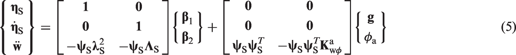
It is noted that equations (4) and (5) are in the modal domain and hence their order is governed by the number of modes of the cavity structure used.
Modal testing
In the previous section, equations (4) and (5) can be solved to estimate the states and the modal displacement and modal velocity of the structure for the specified inputs. However, it is often seen that the response estimated is not accurate due to the modelling inaccuracies associated with the FE model of the cavity structure. Some of the reasons for these inaccuracies may be related to the modelling of boundary conditions, joints, damping and due to lack of the exact knowledge of the material properties of the cavity structure. Modal testing is a method to obtain an experimental estimate of the natural frequencies, mode shapes and modal damping factors of a structure. 29 The experimental estimate is generally considered to be more accurate than an analytical or a numerical/FE estimate of these quantities. An experimental estimate can be used as a reference to judge the accuracy of a structural dynamic FE model. It can also be used to update an FE model to improve its correlation with the modal test data. 30
FE model updating of the plant
To improve the correlation between the FE model and the experimental data, the FE model is now updated. The inverse eigen-sensitivity method (IESM) that is a widely used method of model updating can be a good choice in this regard.30,31 In this method, the uncertain parameters of the cavity structure FE model are corrected so as to reduce difference between the experimental and the FE model eigenvalues and eigenvectors. The updating parameters need to be chosen such that they represent the perceived modelling inaccuracies in the FE model of the cavity structure. The formulation of the IESM to update the mass and stiffness matrices (
Let

The eigenvalues and eigenvectors are related to the updating parameters pi, of the FE model through an eigenvalue problem and the symbol ‘f’ in the above equation denotes that relationship. The updating parameters, pi, are the uncertain parameters of the structure like material property, density, dimensions like thickness, joint parameters or some parameter related to the boundary conditions (like stiffness of springs representing flexibility at the boundary). This last type of parameter is chosen in the experimental study reported in the section ‘Experimental study’. Equation (6) can be linearized about the corresponding analytical eigenvalues and eigenvectors. These equations for modes 1, 2,…, m can be combined to obtain following matrix equation:
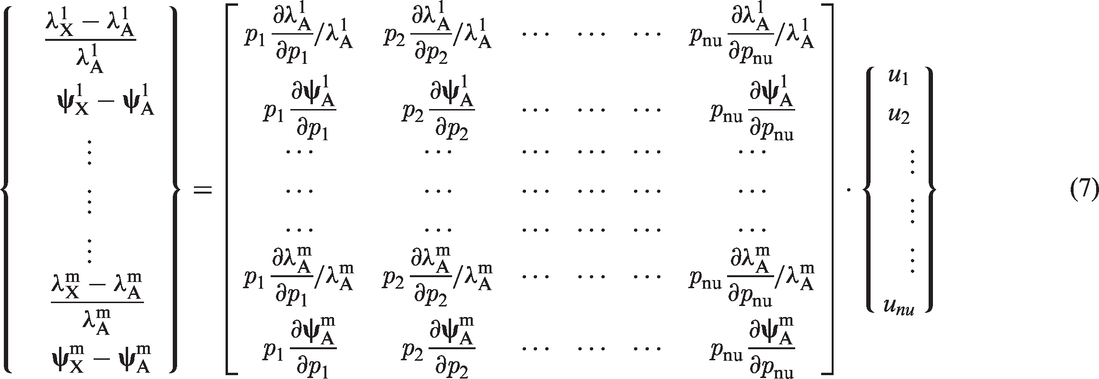
Above steps need to be repeated in an iterative way till convergence is obtained. FE model based to the values of the updating parameters at the convergence is an updated FE model.
The modal damping factors identified through the modal test and the eigenvalues corresponding to the updated FE model are used to construct the matrix
State observer
A stochastic state observer in the form of Kalman filter is used to estimate the states and output of the plant. Kalman filter is an optimal state observer for a system in the presence of process and measurement noise. As shown in Figure 1, the accelerometer output is used to estimate the state vector State observer.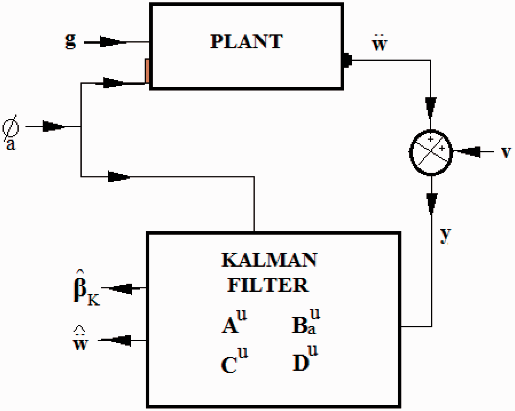
Using equations (4) and (5), including the disturbance


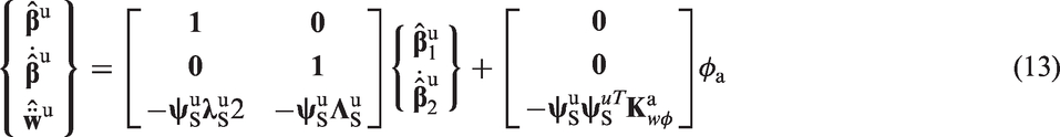
Let the number of modes of updated structural model be Nd. The size of the matrices


The measured acceleration
The state equation of the Kalman filter is written as,

LQG controller
The LQG controller for ASAC is developed as a combination of the LQR with gain Linear quadratic Gaussian controller for ASAC.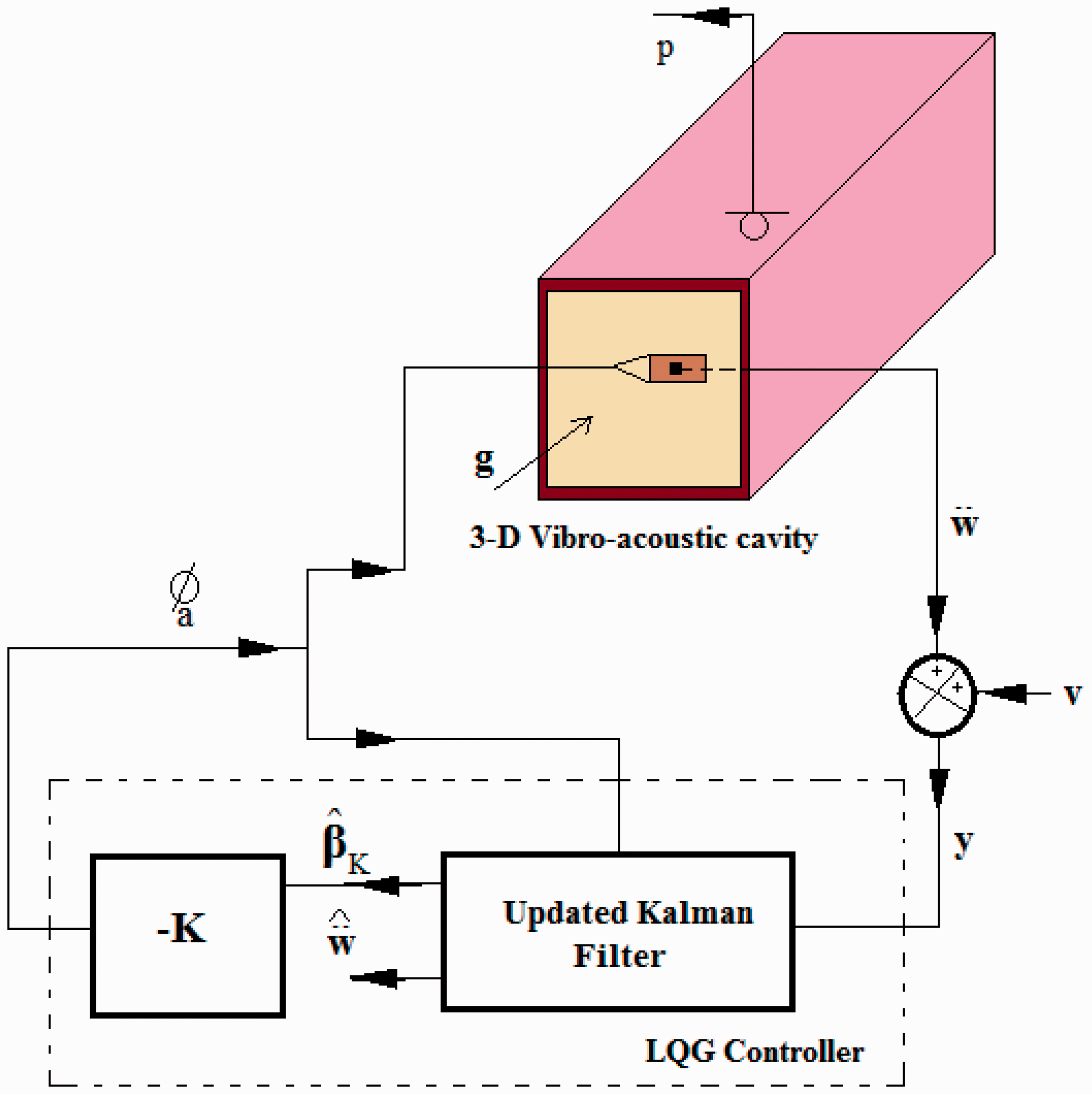
The objective function or the performance index for the LQR is framed to minimize the structural vibrations along with the control effort. Minimization of the performance index, J, gives the full state feedback gain

The weighting matrix
The weighting matrix
The structural-acoustic coupling matrix in the modal domain is given by,

The variable


The weights can be computed for
The combination of Kalman filter and the LQR controller gives the state equation for the LQG regulator as,

The control signal (which is the voltage input to the actuator) is given by,

As seen from the above equations, the input to the LQG regulator is the measured acceleration (
The LQG scheme presented above thus gives an indirect control of the acoustic field through the control of structural vibrations by taking care of the relative importance of various structural modes as determined by the strength of their coupling with various acoustic modes.
Experimental study
This section presents an experimental study to actively control interior noise in a 3D rectangular-box cavity of size 0.265 m × 0.317 m × 0.686 m using the method proposed in the previous section. The cavity is shown in Figure 3. It is made up of thick acrylic sheets with a flexible steel plate of dimensions 0.265 m × 0.317 m and thickness 0.000943 m fixed at its one end. A piezoelectric patch (DuraAct piezoelectric patch transducer P-876 A12) of size 0.05 m × 0.03 m and thickness 0.0005 m is glued to the flexible plate at the desired location. The top acrylic plate has some holes to insert microphone into the cavity for taking sound pressure measurements.
Experimental vibro-acoustic cavity.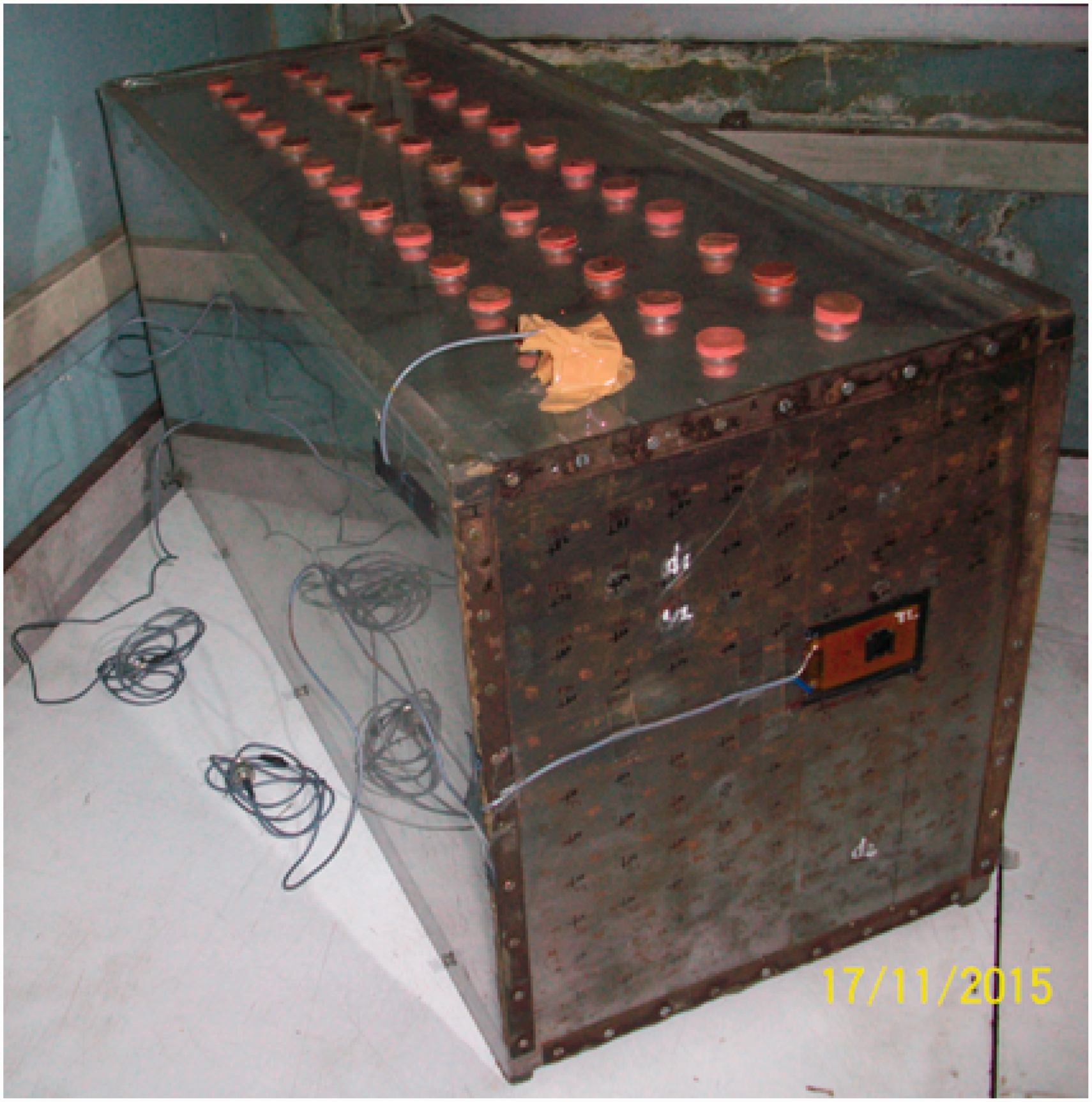
The FE model of the flexible plate has a mesh of 12 × 16 plate bending elements. The plate is assumed to be fixed at its four edges. The density, Young’s modulus and Poisson’s ratio for the plate material are taken as 7735 kg/m3, 2.00e + 11 N/m2 and 0.3, respectively. The other five surfaces of the cavity made up of thick acrylic sheets are treated as rigid.
The portion of the flexible plate with piezoelectric patch is discretized using a mesh of 2 × 2 elements and is modelled using classical lamination theory. The Young’s modulus, density and Poisson’s ratio of the patch are taken as 23.3E + 9 N/m2, 7800 kg/m3 and 0.34, respectively. The value of the piezoelectric strain coefficients e31 and e32 is −8.9678 C/m2 and the value of the dielectric constant ɛ33 is 6.6075 × 10⁻⁹ F/m. The acoustic space of the cavity is modelled with 2688 eight-node solid acoustic FEs with 3315 nodes and with rigid wall boundary conditions at all the cavity surfaces. The density of the medium and the speed of sound are taken as 1.21 kg/m3 and 340 m/s, respectively.
A modal test on the steel plate with the piezoelectric patch glued and the accelerometer (Bruel & Kjaer 4508, sensitivity 100.3 mV/m/s
2
) mounted is conducted to identify an experimental estimate of the structural modal model (natural frequencies, modal viscous damping factors and mode shapes). An impact hammer (ENDEVCO 2302-5, sensitivity 1.016 mV/N) is used to excite the plate as shown in Figure 4.
Experimental set-up for modal analysis (a) modal hammer, (b) FFT analyser, (c) accelerometer, (d) PZT patch, (e) flexible plate, (f) clamping screws, (g) acoustic cavity, (h) microphones and (i) holes for measuring sound pressure.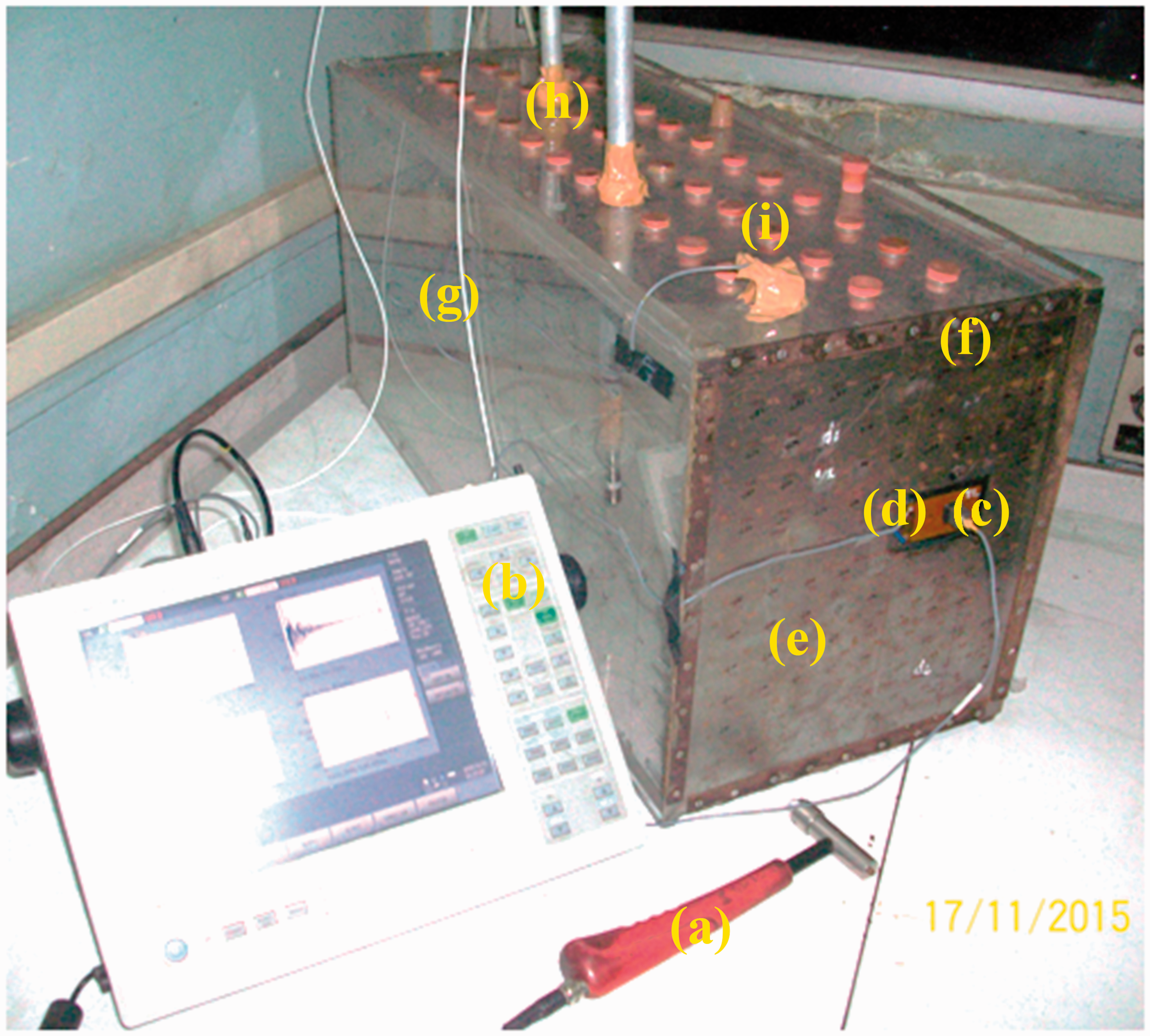
An FFT analyser (ONOSOKKI make CF-7200A) is used to measure the FRFs. FRFs are recorded at 90 points over a mesh of 9 × 10. Generally, the target frequency range for active control of noise in real life cavities like that of a vehicle is around 250–400 Hz. Based on this consideration, the FRFs are recorded over a frequency range of 350 Hz with an objective to suppress noise over this range. FRFs are also recorded with microphone inside the cavity. The FRFs are analysed using a modal analysis software (ICATS). Natural frequencies are also computed from the FE model of the cavity structure. Weak coupling is assumed between the cavity structure and the acoustic domain.
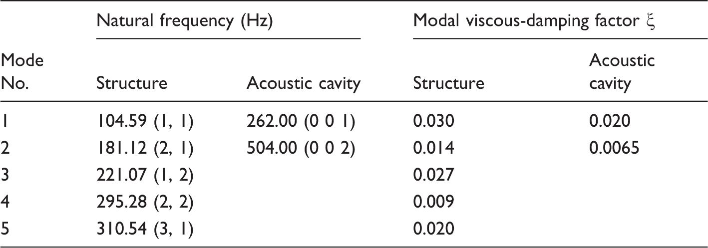
Experimental natural frequencies and damping factors of the cavity structure and the acoustic cavity.
MAC values and FE model and experimental natural frequencies.
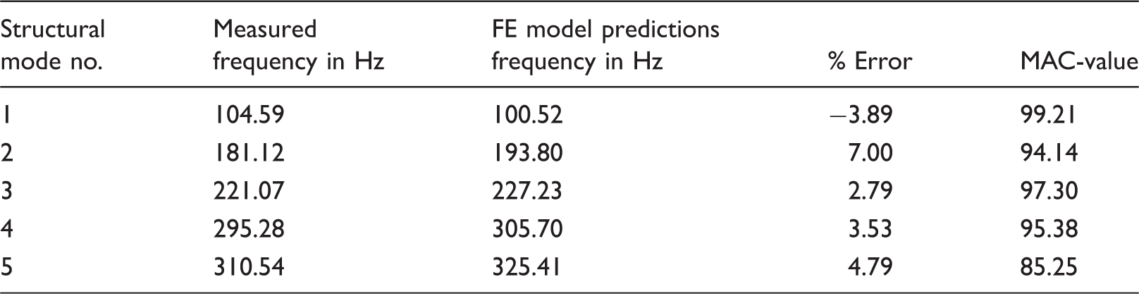
FE: finite element; MAC: modal assurance criterion.
The FE model is now updated to improve its correlation with the experimental data. The choice of the updating parameters is very important in model updating. In the present case, the dimensions of the plate are known fairly accurately. However, the boundary conditions at the clamped sides of the plate are suspected to be in error. The modulus of elasticity and the density of the plate material are the other two uncertain parameters.
The modulus of elasticity of the plate material is identified through a separate updating step on a free-free beam of the same material. Modal test is carried out to identify its natural frequencies which are then used to update the FE model of the beam. The density is calculated from the knowledge of mass and volume of the beam and therefore only the modulus of elasticity is used as the parameter in updating.
The estimates of the modulus of elasticity and the density of the plate material thus found from the beam specimen are used to build the cavity structure FE model. This model now can be said to have modelling inaccuracies mainly limited to the boundary conditions. Hence the boundary conditions are parameterized by representing their flexibilities through springs of unknown stiffnesses as shown in Figure 5. The linear and the torsional springs are introduced at all the three DOFs of all the nodes on the four edges of the plate. The sensitivities of the natural frequencies to the torsional stiffnesses, representing the stiffness introduced for the rotational DOFs, are seen to be much higher than the sensitivities to the linear stiffnesses, representing the stiffnesses introduced for the translational DOFs. In view of this, the torsional stiffnesses are chosen as the updating parameters. Further, these stiffnesses are assumed to be same for the nodes on the two opposite/parallel edges. At each node there are two rotational DOFs and hence two torsional stiffnesses are there. However, only those torsional stiffnesses whose axis is parallel to the edge, on which that spring lies, is updated since the plate natural frequencies are not much sensitive to the other torsional stiffness. In this way there are four updating parameters designated as KθxH1, KθxH2, KθyV1 and KθyV2. The lateral DOFs are kept fixed, i.e. the transverse displacements at all the nodes on the plate edges are restrained.
Torsional spring stiffness updating parameters for the plate.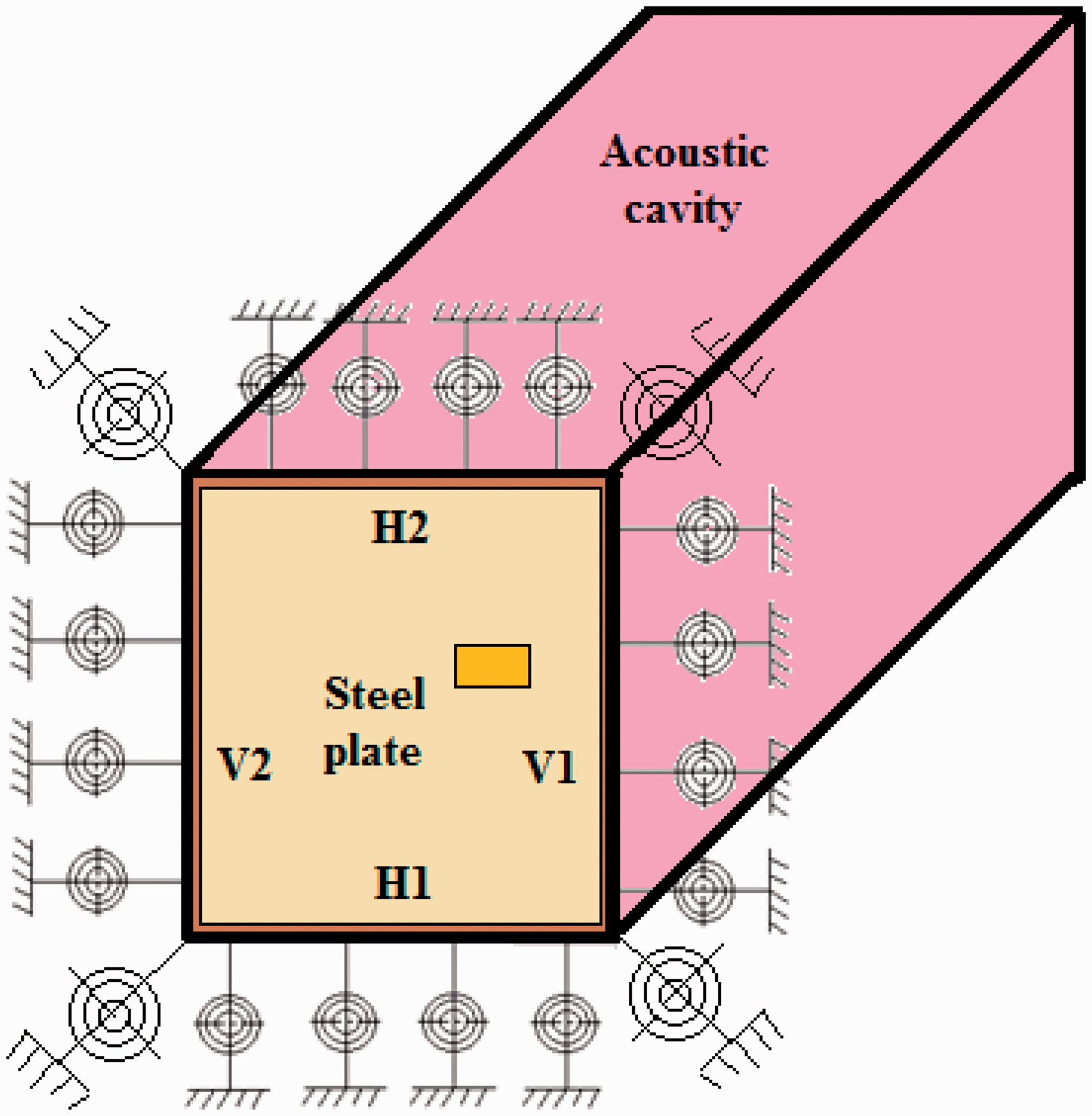
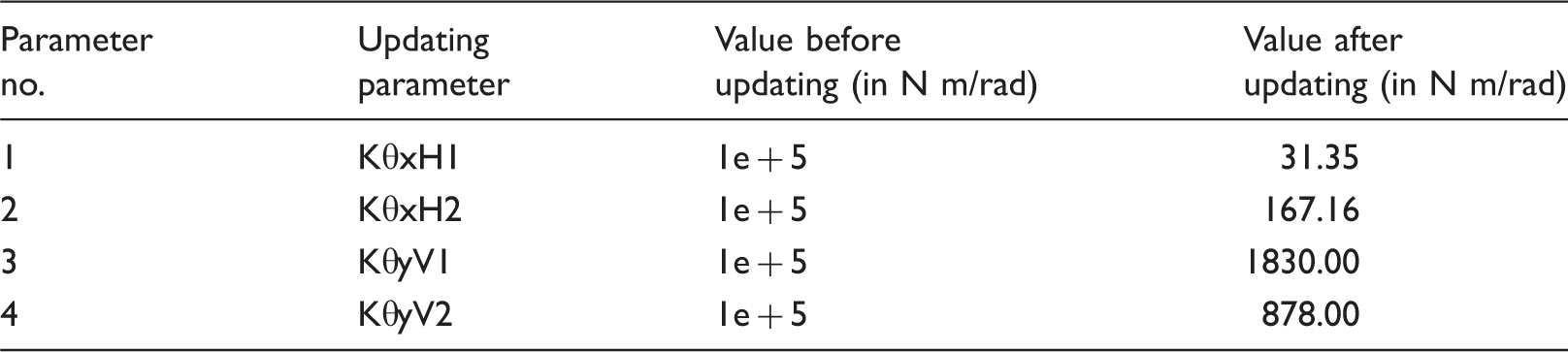
The initial and the values of the updating parameters after updating.
Comparison of the measured and the updated FE model natural frequencies and the mode shapes.
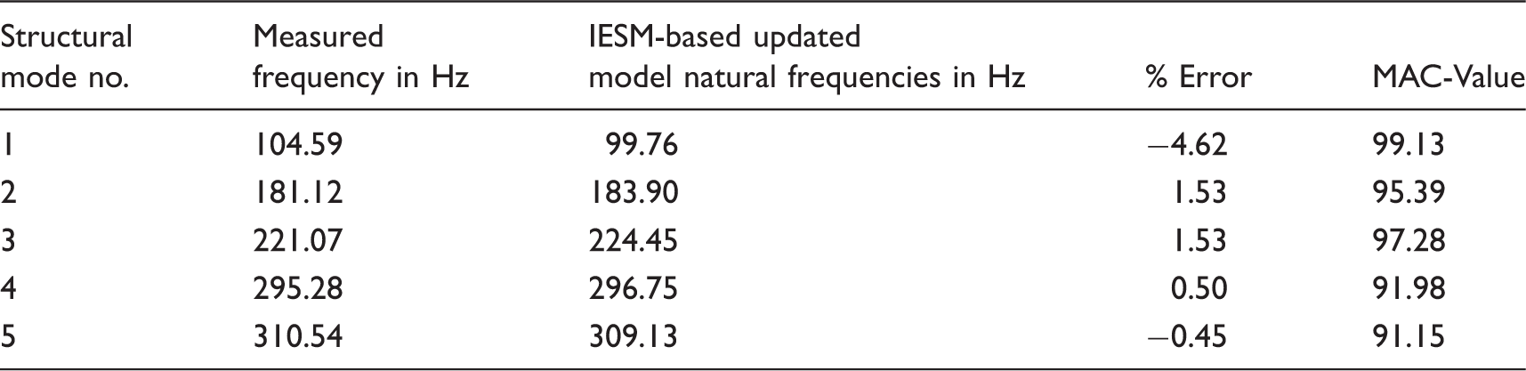
FE: finite element; MAC: modal assurance criterion.
For FRF comparison, the damping is included in the FE model via modal damping factors identified from the analysis of the measured FRFs (Table 1). A comparison of the overlay of the inertance-FRF (FRF-H161,84) at a translational DOF with the corresponding measured FRF before and after updating is shown in Figure 6. This FRF represents ratio of acceleration and force in the frequency domain. The updated model FRF shows a significant improvement in correlation after updating.
Comparison of the overlays of inertance FRF-H161, 84 using IESM with the measured FRF for FE model: (a) before updating and (b) after updating.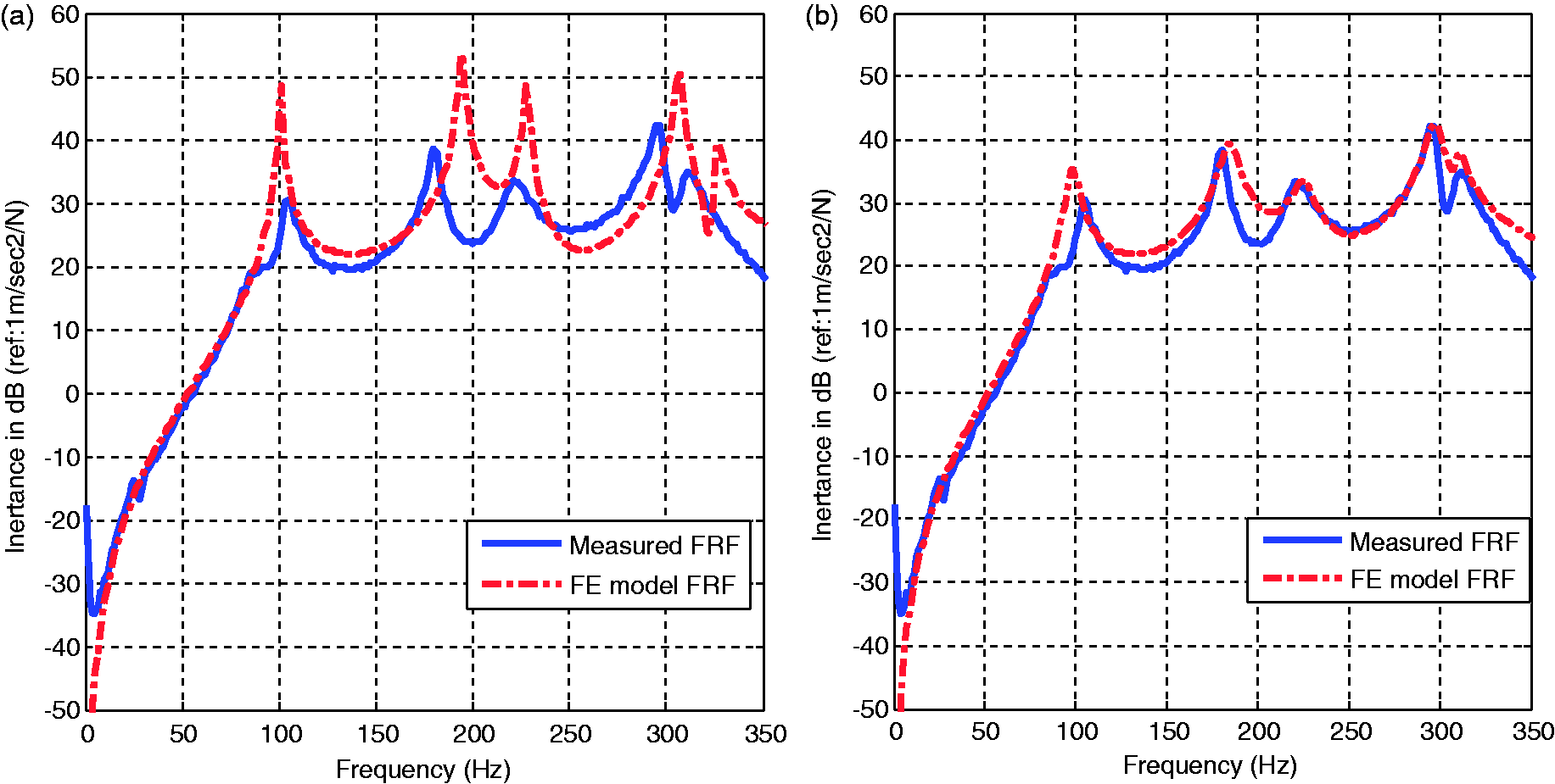
By solving the eigen-value problem in updated mass and stiffness matrices,
Modal structural-acoustic coupling coefficients (
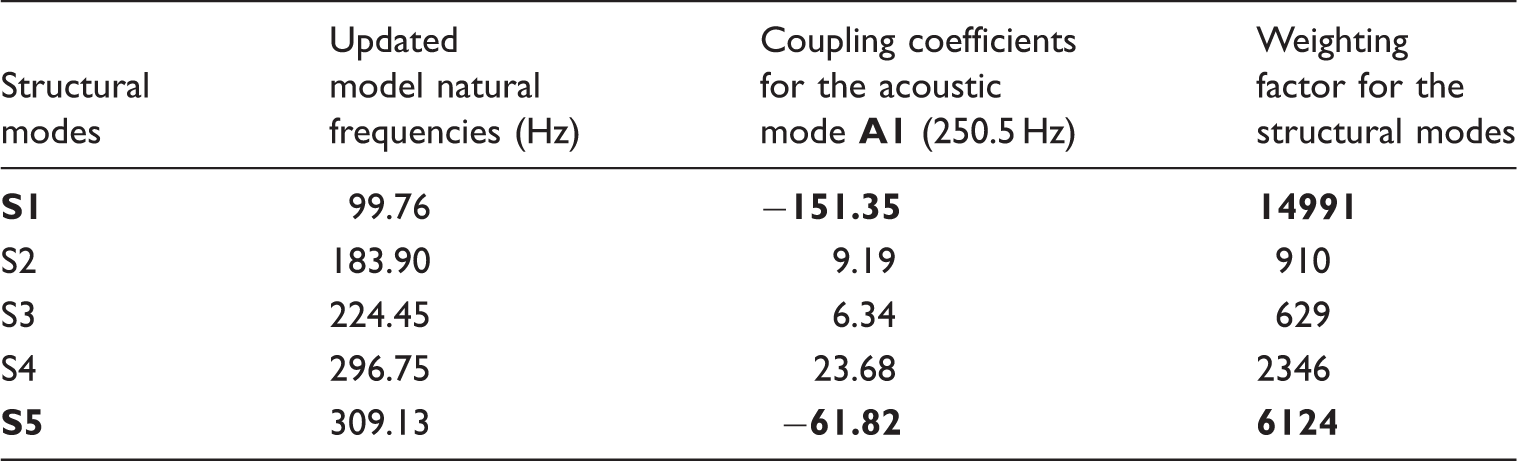
Figure 7 shows the photograph of the entire setup used for active structural-acoustic control to reduce noise inside the 3D rectangular box cavity.
Experimental setup used for ANC: (a) vibro-acoustic cavity, (b) ENDEVCO signal conditioner, (c) dSPACE controller board, (d) analogue low pass filter, (e) controller, (f) piezoelectric voltage amplifier and (g) CRO.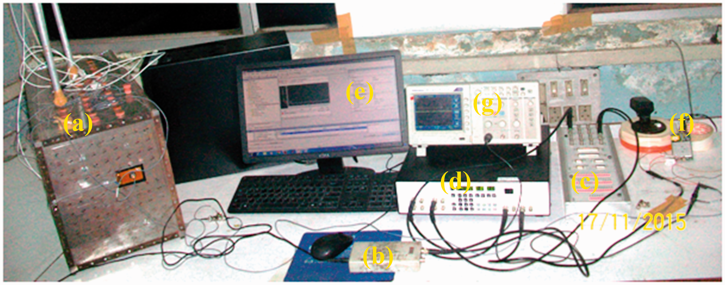
The output from the accelerometer mounted at the location (coordinates: x = 0.183 m, y = 0.190 m on the structure) is fed to the signal conditioner. The signal is then low pass filtered with a cut-off frequency of 340 Hz. The signal is then fed to the dSPACE controller board. The LQG regulator designed for the cavity is discretized using a sampling interval of 0.0011 s and is loaded on the controller board. The sampling frequency was chosen so that it is more than twice the maximum frequency range (350 Hz in the present case) over which noise reduction is targeted. Also a low pass antialiasing filter was used before A/D converter to ensure that the signal from the sensors is free of any aliasing effects. A low pass filter was also used after the D/A converter to ensure that control signal is free from frequency components beyond this range.
The output of the controller board is again low pass filtered and is fed to the piezoelectric actuators after amplification. Two microphones are mounted inside the cavity at the locations (x, y, z = 0.082 m, 0.082 m, 0.250 m) and (x, y, z = 0.131 m, 0.2050 m, 0.50 m) to record the acoustic pressure with and without control.
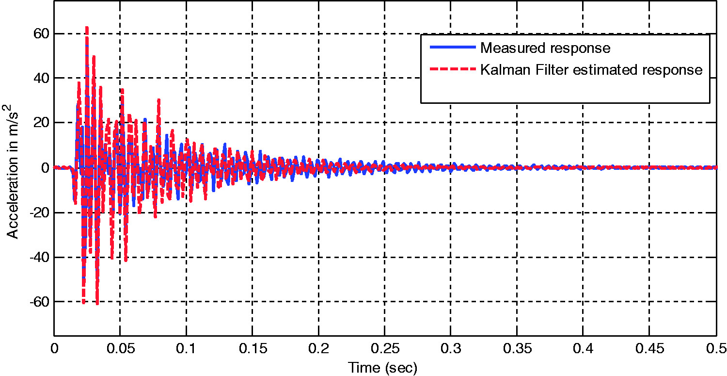
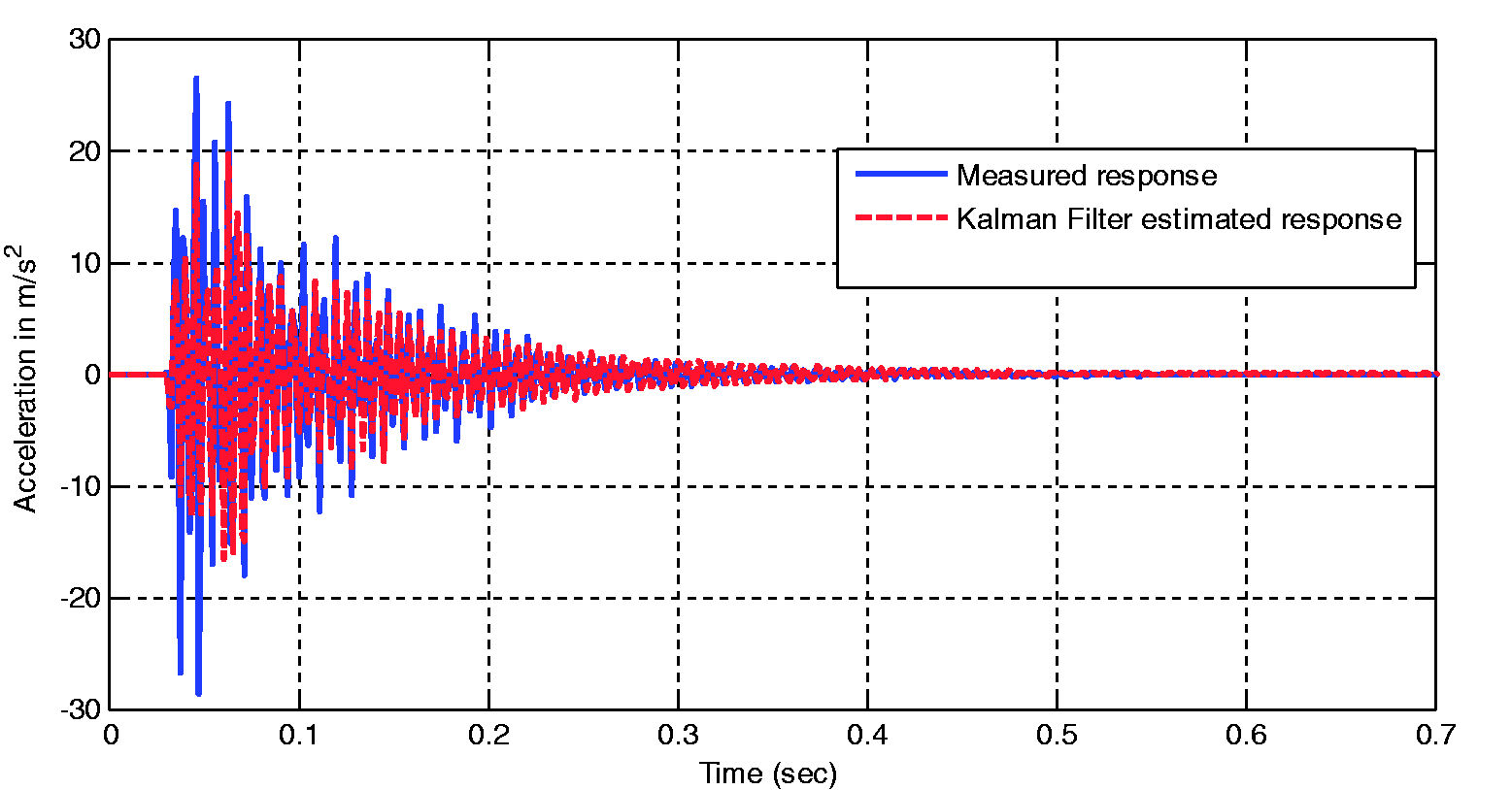
The performance of the Kalman filter and the active control system is experimentally evaluated for an impulse disturbance acting on the plate. Figure 8 shows three locations L1, L2 and L3 on the plate. Acceleration measurement taken at L1 is used as input to the Kalman filter. An impulse disturbance is applied at a certain location (L3) on the flexible plate and the accuracy of the Kalman filter to estimate the accelerations at locations L1 and L2 is checked. Figure 9 shows a comparison of the estimated acceleration with the measured acceleration at location L1. It is noted that the acceleration ( Kalman filter performance evaluation at L1 and L2 location. Comparison of the estimated acceleration with the measured acceleration at location L1. Comparison of the estimated acceleration (L2) with the measured acceleration at location L1.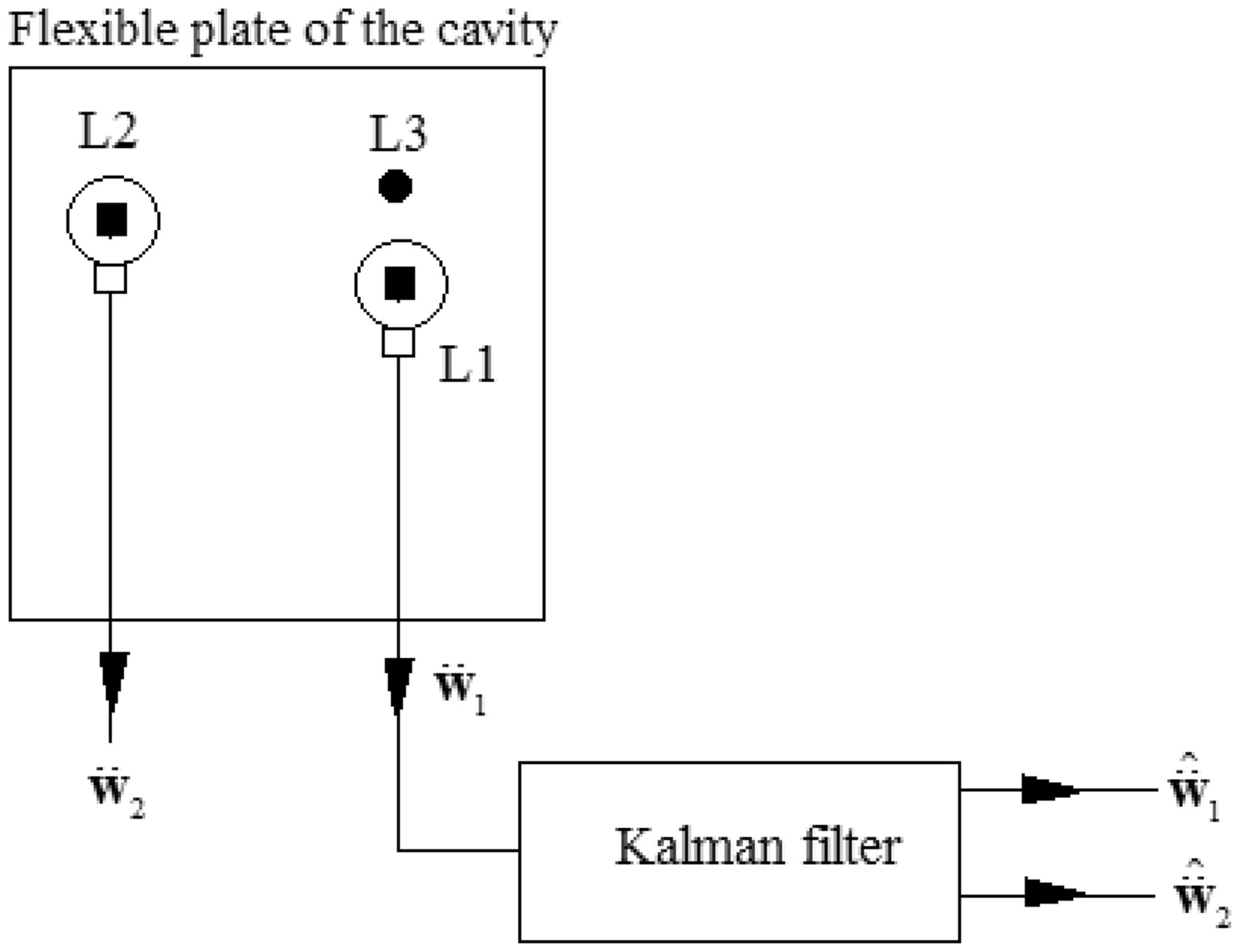
The control performance of the proposed controller is evaluated by measuring the structural-acoustic FRF with and without control. The FRF between the Fourier transforms of acoustic pressure at a node inside the cavity and transverse force disturbance at a node on the flexible plate is measured. Figure 11 shows this FRF with and without control at a microphone position in the cavity. In this figure, the structural and the acoustic resonances of the system are identified with symbols Frequency response function with and without control at a microphone position in the cavity.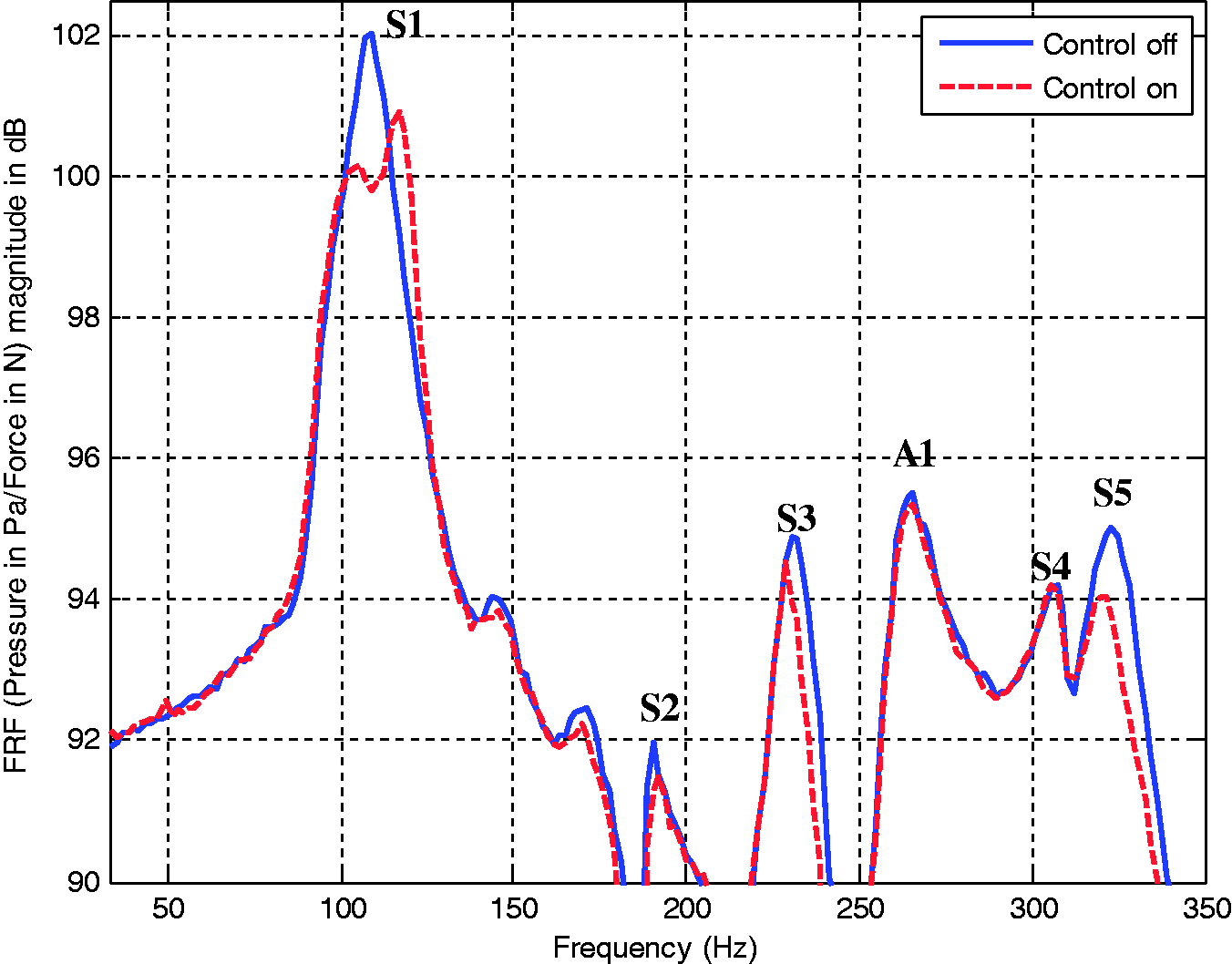
It is observed that there is reduction of noise but it is on a lower side. It appears that more than one piezo actuator is required to be able to alter the vibration behaviour of the plate sufficiently. Current study is based on a single such patch and further investigation is necessary to see the performance using multiple piezo actuators.
It is thus seen that the proposed methodology of active structural acoustic control with weighting factors chosen based on the coupling coefficients and the observer designed using a system identification approach is effective in reducing the noise inside the cavity.
Conclusions
This paper proposes a feedback active noise control technique based on ASAC incorporating system identification. System identification based on modal testing and FE model updating is proposed to develop an accurate state observer in the form of Kalman filter. An LQR controller that utilizes the knowledge of structural-acoustic coupling coefficients to weight different structural modes to minimize structural vibrations and indirectly reduce the interior noise in a cavity is proposed. An LQG controller is built by combining the Kalman filter based on the updated model of the plant and the LQR controller. The proposed active control methodology is validated experimentally on a 3D rectangular box cavity with a flexible plate. A modal model of the flexible plate is identified through experimental modal analysis in 0–350 Hz range. The experimental eigenvalues and eigenvectors are used to update the undamped FE model of the plate. The updated FE model and the modal damping factors identified through modal analysis are used to build the Kalman filter. The structural-acoustic coupling coefficients are predicted by using the updated FE model of the plant and the FE model of the 3-D rigid wall acoustic cavity, which are then used to design an LQR controller.
The LQG controller so designed is implemented on a dSPACE controller board. The experimental active control system is implemented with an accelerometer mounted on the plate whose output is fed to the Kalman filter. The voltage control signal from the LQG controller is fed to the collocated piezoelectric actuator glued to the plate. The results of the experimental study show that the Kalman filter based on the updated model is able to estimate the acceleration on the plate both at the location of the sensor as well as at other locations reasonably well. The frequency response of the acoustic pressure inside the cavity to a force disturbance on the plate with control shows that the control system is able to selectively damp those modes that couple well with the acoustic modes in the cavity. The proposed controller therefore allows utilizing the control effort in a more judicious and optimal manner.
Footnotes
Declaration of conflicting interests
The author(s) declared no potential conflicts of interest with respect to the research, authorship, and/or publication of this article.
Funding
The author(s) disclosed receipt of the following financial support for the research, authorship, and/or publication of this article: The financial support for this work under the project DARO/08/1051606/M/I provided by Aeronautics Research and Development board (Structures panel), Ministry of Defense, Government of India, is gratefully acknowledged.