
Abstract
The present work aims to study the water-stop tray, a front-loading component of a washing machine. As most of the components of washing machines, the water-stop tray suffers significant vibrations especially when the spin speed increases. A vibrational analysis of the current typical design was realized. Then, four modified trays were investigated and a hammer impulse response was recorded using 13 accelerometers in order to measure the frequency response of each tray. The results allow to identify the key parameters that affect the vibrational response of a water-stop tray. Finally, the comparative analysis among the different designs allows to select the tray with the lowest vibration amplitude.
Introduction
This technical paper aims to study a specific component of front-loading washing machines, the bottom water-stop tray (Figure 1). Although not every washing machine is equipped with such a tray, this component is often considered fundamental by leader companies in order to prevent flooding in case of water leaks. The water-stop tray is subject to a significant amount of vibrations. Moreover, being a plastic element fixed to a metal frame, it is often the main noise source which sometimes led manufactures to avoid to adopt such a useful component.
Photos of the washing machine and the current produced water-stop tray.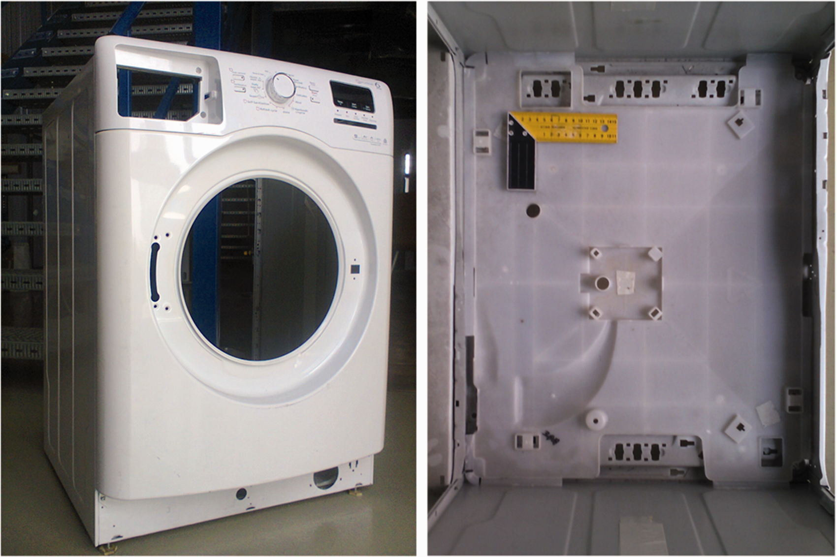
A trend for increasing the capacity load of washing machines while reducing their weight has recently pushed the adoption of light and thin components. Meanwhile, the spin speed is generally increased to improve washing capability and as consequence, vibration issues are often more severe on modern machines. From a vibrational point of view, washing machines can be classified as a vertical or horizontal axis of rotation. 1
In a fully automatic washing machine, unbalanced masses of clothes in the centrifuge drum are responsible for severe vibrations. These occur more frequently in the spin phase, when the drum rotates at a high speed, while the pressure of the clothes against the inner wall of the drum increases acting a larger unbalanced force. Large vibrations during the spinning step are particularly severe in washing machines with horizontal axis.1–3 These vibrations are transferred from the supports of the frame to the rest of the machine components. Although rubber cushions help reducing these vibrations and innovative springs and shock absorbers between the outer tub and the frame using MR dampers have been proposed recently, severe vibrations are still the main cause of malfunctioning of washing machines. Moreover, the noise generated by the interaction of the cabinet with the suspension system and with all other plastic components, including the water-stop tray, is often particularly annoying. Meanwhile, with the improvement of living standards, comfort expectations have increased and the design of washing machines is currently focusing on reducing vibration and noise issues.4–7
The goal of this study is the identification of the key parameters in the design of a water-stop tray with a reduced mobility. A preliminary analysis on the current water-stop tray was carried out, and then four different modified trays were evaluated. The analysis was performed by comparing modal testing results and making changes in different parts of the trays. A structural dynamic behavior analysis was realized using an impulse hammer. Thirteen accelerometers were arranged on the trays to identify both the nodal lines and the frequency peaks. The analysis of the results allowed to identify the parameters that influence the behavior of the trays. In particular, the rib positions have shown to influence the mode shapes, the density and distribution of the ribs influence the natural frequencies of the tray, and the height of the ribs influences the amplitude of the resonances.
The design of water-stop trays
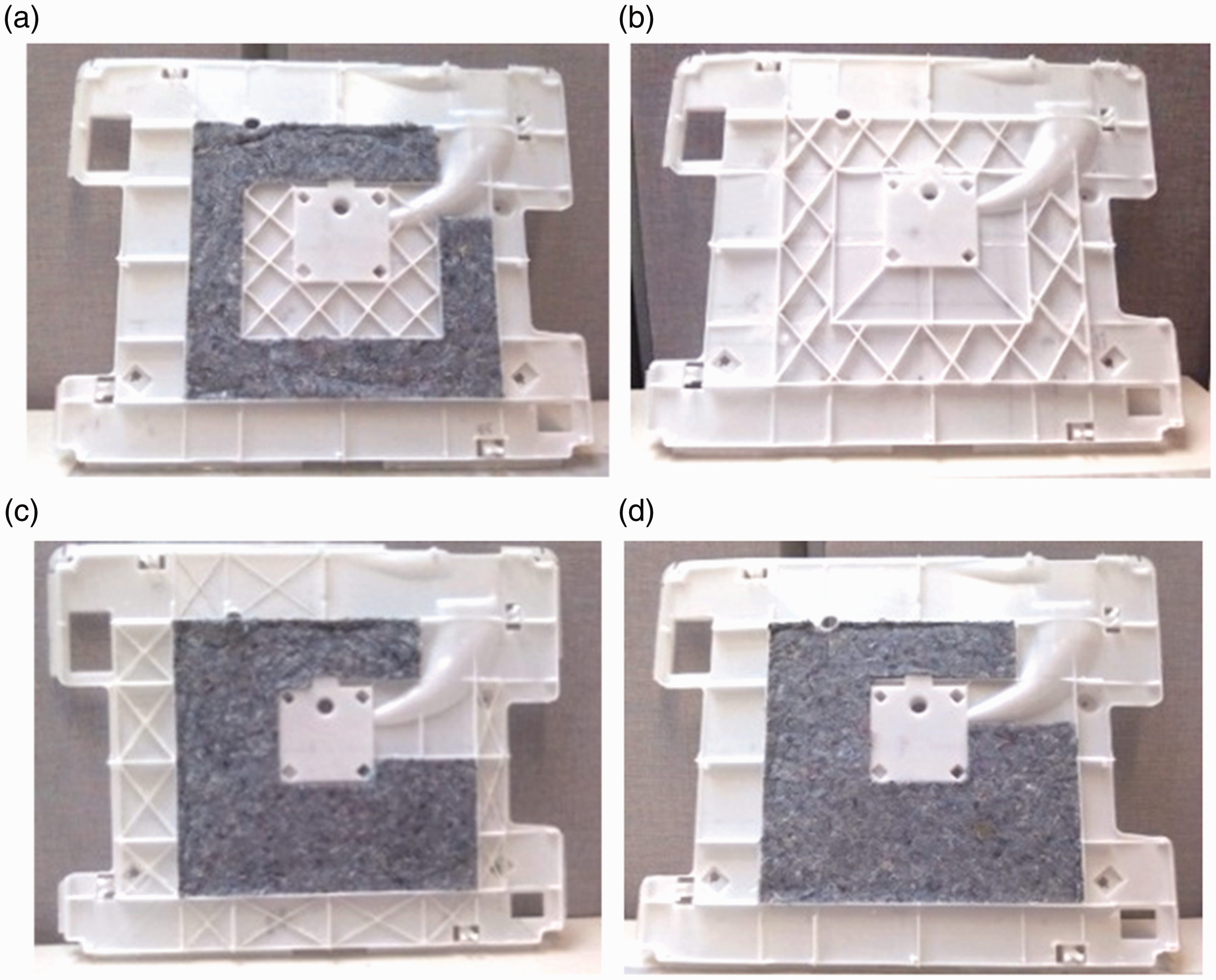
The current design of a commonly used water-stop tray has ribs in its bottom face to create a stiffer structure. The tray selected as a case study is 0.42 m by 0.57 m. The design of typical sandwich structures (Figure 2) suggested considering the core pattern of sandwich structures to improve the design of the current water-stop tray. Preliminary evaluations about the feasibility of realizing these shapes led to the adoption of a lattice shape with diagonal ribs in the two directions. Using additive manufacturing, four different shapes were manufactured and tested. The first one, shown in Figure 3(a), combines the structural reinforcing core ribs with the application of perimeter sound-absorbing material, typically used in the side panels of washing machines. A 1 cm thick layer of fiber material obtained from waste processing textile was used. The central grid was tightly woven to strengthen the center of the component, giving the same ratio between the height of the ribs and the space between them. The second design, shown in Figure 3(b), had a less dense grid of the ribs which occupy also the area where the sound-absorbing material was in the first design. In the third design, shown in Figure 3(c), the reinforced ribs were placed at the edges of the tray and the height of the ribs was half of that in the previous two designs, while all the central space, it hosted a sound-absorbing panel. The fourth design, shown in Figure 3(d), had no additional ribs with respect to the current design, but it had sound-absorbing panels in the center part.
Honeycomb core material for a sandwich structure. Design proposals for the modified water-stop tray. (a) First modification, (b) second modification, (c) third modification, and (d) fourth modification.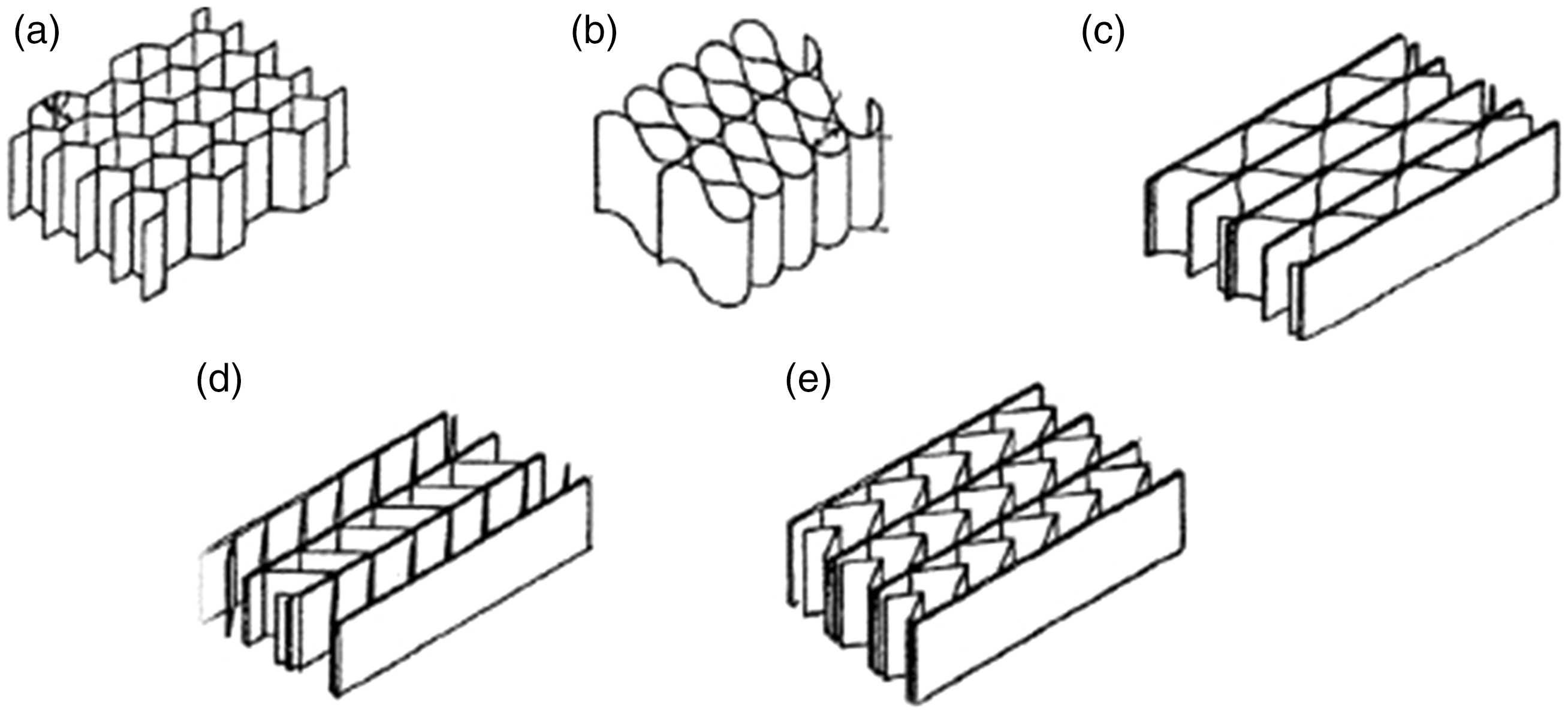
Comparison of the alternative design
The modal test of each tray was performed using 13 accelerometers located according to the typical modes of rectangular plates. These have straight nodal lines symmetrical within the rectangular surface. The modes (1,1), (2,2), (3,3), and (4,4) were hence supposed to dominate the vibration of the tray. The nodal lines of these three ways are at 1/4, 1/3, 1/2, 2/3, and 3/4 of the length in both the vertical and horizontal sides. These nodal lines were marked on each water-stop tray and used to arrange the accelerometers (Figure 4).
Water-stop tray for the hammer test with the accelerometers located in the nodal points.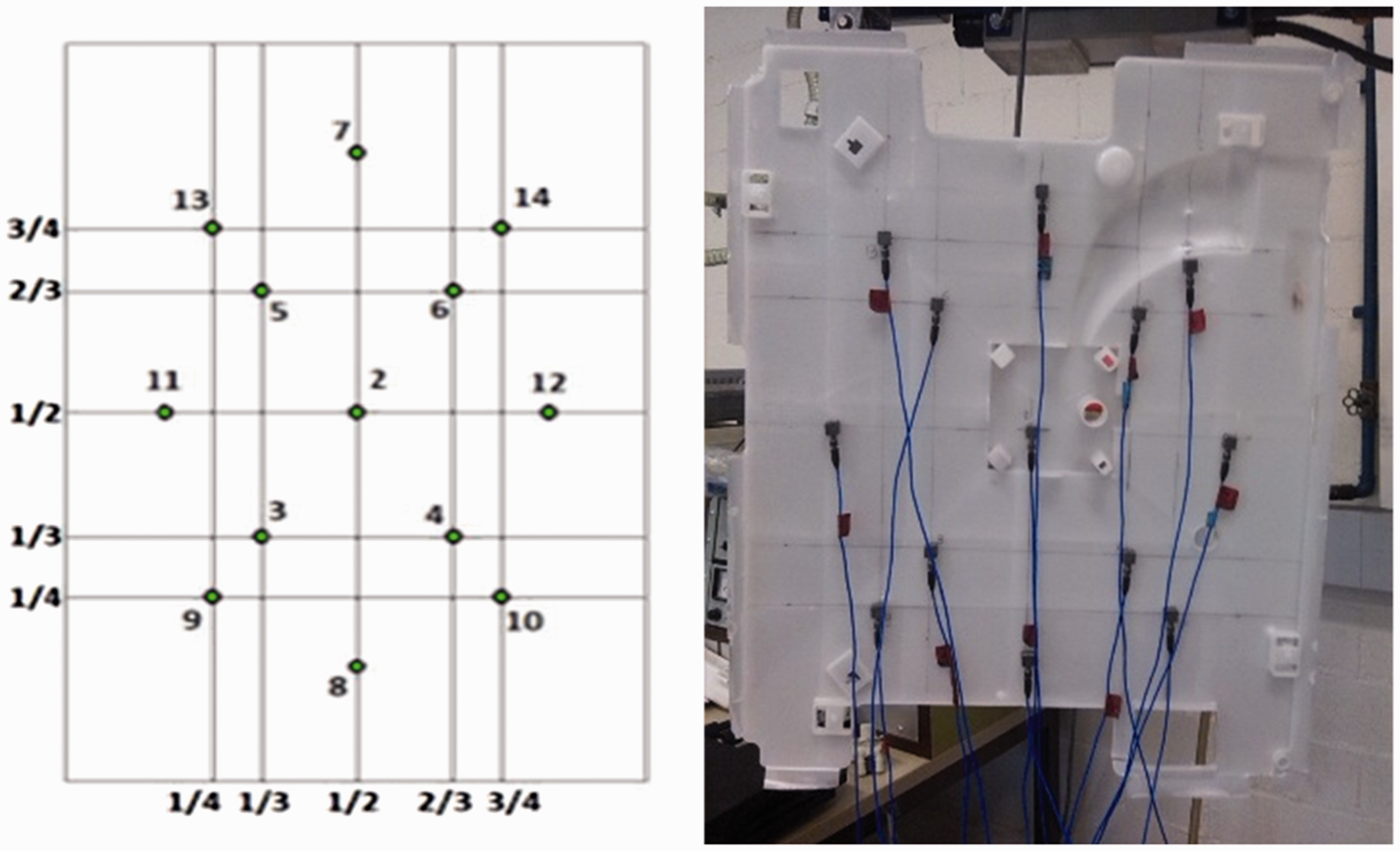
In theory, the optimum distribution of the accelerometers for each mode would be along the intersection of the nodal lines and at the center of the areas obtained by these lines.6,7 In this way, it would be possible to observe both the minimum and maximum vibrations. Based on these considerations, the measurement grid was created taking into account the number of available accelerometers. For example, given the shape of the first mode (1,1), the sensor was located in the center of the water-stop tray where the maximum amplitude was expected (number 2 in Figure 4). As regards to the modes (2,1) and (2,2), the accelerometers were located in the positions 7, 8, 11, and 12, and in order to detect the peaks of these modes, accelerometers were also located in the positions 9, 10, 13, and 14. For the modes (3,1), (3,2), (3,3), (2,3), and (1,3), the accelerometers in the positions 3, 4, 5, and 6 were arranged. Finally, the accelerometers in the positions 7, 8, 9, 10, 11, and 12 were used to observe the peaks of the mode (4,4).
As evident from the water-stop tray picture in Figure 4, the tray has reinforcements and asymmetrical elements which differentiate it from an exact rectangular shape. In addition, the ribs under the tray modify the nodal lines from those provided theoretically. These elements were assumed to have limited impact on the modal lines.
The choice of the way to support the tray during the test considered various factors.8,9 A free boundary condition was chosen for the experiments when the tray was freely suspended in the space. In practice, the tray was hanged from one side. In this condition the six rigid body modes were cancelled and a pendulum drive mode was predominant at low frequency.
The mode presented in the perpendicular direction to the plate was considered negligible since the tray was excited perpendicularly to its surface. The points of impact of the hammer were almost at the center of the object, i.e. in the center of the three axis, as shown in Figure 5.
Dynamic response in three points for the current design of the water-stop tray.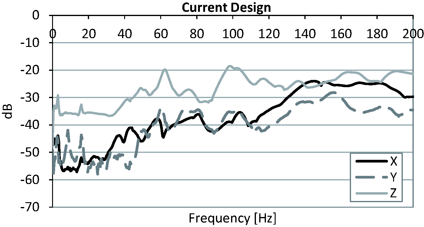
Measurement equipment
For the excitation, an impact hammer Brüel & Kjær Type 8202 was used. 11 This device is a hammer with a force transducer type 8200 attached on its head. The force transducer measures the magnitude of the applied force which is supposed to be equal in magnitude and with opposite direction to the one transmitted in the structure. The impact force magnitude level is determined by the hammer velocity when the impact occurs and by the mass of the hammer head. The force pulse transmitted, ideally a Dirac signal, has a half-sine shape. This form of pulse has a frequency spectrum content flat up until a certain frequency and above this, it diminishes and becomes uncertain. The duration of the pulse is linked to the stiffness of the contacting surfaces, the tip of the hammer and the structure, and the mass of the hammer head. Stiffer contacting surfaces will have shorter pulse duration, 6 since the duration of the pulse is inversely related to the natural frequency. The selected hammer imparted to the tray a smooth excitation spectrum over a broad frequency range.
Results
This section reports the results of the modal analysis. The results are analyzed only in the frequency range 0–200 Hz, since this range allows to measure the main natural frequencies and mode shapes. Moreover, the interval seemed appropriate considering that the critical frequency during the spin cycle of a washing machine is about 22 Hz (1400 r/min).
Basic design of the water-stop tray
Figure 5 shows the response of the tray obtained from the linear average of the responses of all the 13 accelerometers at the impact points for the axes x, y, and z. The results show that the response in the z direction had a great influence. The graph indicates peaks at 49, 62.5, 75.5 Hz, and most importantly at 98.5 Hz where the acceleration value resulted in being −18.4 dB.
First modification of the water-stop tray
The analysis then focused on the modified tray design. In this case, a different behavior was observed in the z direction. In fact, compared to the current design of the water-stop tray, the peaks have lower intensity, being −19.2 dB at 50 Hz and −22.9 dB at 65 Hz. By comparing the response in Figure 6 with the corresponding one in Figure 6, it emerges a general improvement in the vibration response, although some large vibration occurred at 134 Hz.
Dynamic response for the four modified design of the water-stop tray. (a) First modification, (b) second modification, (c) third modification, and (d) fourth modification.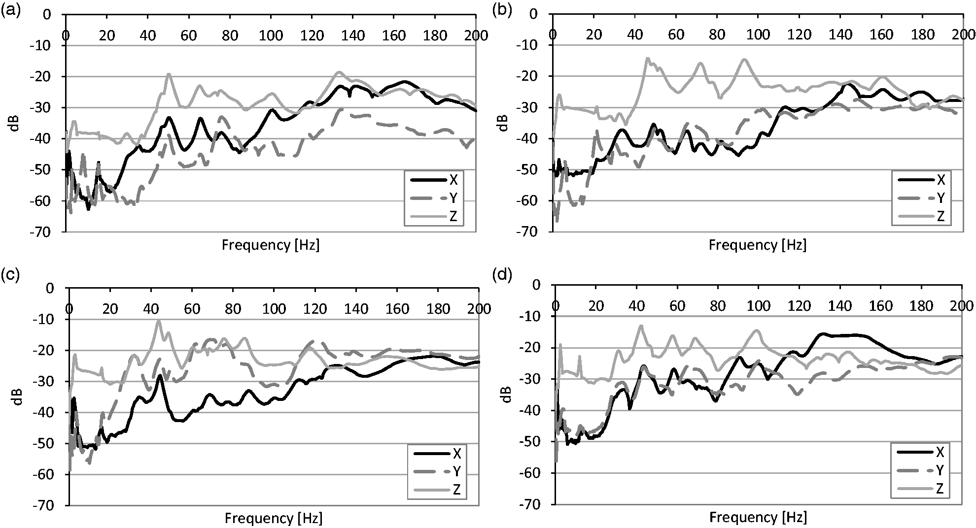
Second modification of the water-stop tray
The results for the second modified tray were significantly different from those of the basic design. The response had peaks only at higher frequencies, and the behavior at low frequencies improved considerably too. There were improvements in both x and y directions, where the vibration was very low up to 100 Hz, while the response in the z direction was still the most significant, although the peaks were generally attenuated along all the spectrum. The three resonances at 46.5, 72, and 93.5 Hz in the z direction resulted similar in absolute amplitude.
Third modification of the water-stop tray
In the third modified design, the response in all directions shows a deterioration with many peaks as a consequence of a high mobility. In particular, not only the dynamic response in the z direction was poor, but in the y direction the vibration reached a really high intensity. Compared to the basic design of the water-stop tray, Figure 6 shows that the third modification of the tray does not give any appreciable improvement.
Fourth modification of the water-stop tray
The response for the fourth modified water-stop tray shows multiple and high peaks at low frequencies, especially below 100 Hz. Compared to the trays analyzed previously, this design proves to be the worst having high peaks at 2.5 and 42.5 Hz where it reaches −13.5 dB.
Discussion and conclusions
Looking at the results of the actual design of the water-stop tray, there is a significant response at low frequencies with several natural frequencies. The actual tray vibrates with great intensity at 7 Hz due to longitudinal movements, at 15 Hz for movements in all directions, at 36 Hz for transverse movements, and at 50 Hz for longitudinal ones. Obviously, these results should consider that the tray was tested in free conditions and was vertically suspended.
The analysis shows that in order to minimize the noise and vibration of the water-stop tray, this needs to be reinforced mainly in the z direction. This is possible with major supports or using ribs in order to strengthen the tray. Combining the results in all the directions for each tray and comparing them (Figure 7), it is evident that the first modified design proposal gives the best response, especially in the frequency range where most of the vibration of a washing machine occurs.
Dynamic response for all the modified designs and the current water-stop tray.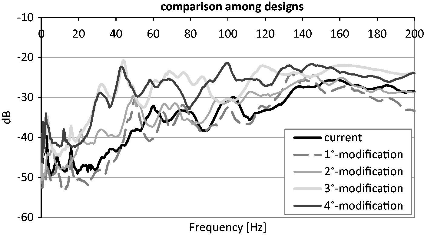
The results obtained in all directions show only partially the response of each modified design. Since for all the variations, the z direction was always the one with the highest influence and where the main vibration occurred, the comparison focused on the response of the different designs only in this direction. This analysis confirmed that the best response would be given by the first modified design proposal.
Finally, the present study allowed to establish that stiffening the central area of the tray with ribs arranged in a honeycomb pattern with a 1 cm thick fiber material allows to get a significant reduction in the vibration of the current water-stop tray.
Footnotes
Acknowledgments
The authors would like to thank the help of Giuseppina Iuliano who helped performing some measurements reported in this paper.
Declaration of conflicting interests
The author(s) declared no potential conflicts of interest with respect to the research, authorship, and/or publication of this article.
Funding
The author(s) disclosed receipt of the following financial support for the research, authorship, and/or publication of this article: The support of the NSERC DG to Dr. Berardi s Lab and research group is acknowledged too.