
Abstract
In this study, an magnetorheological (MR) damper has been designed based on its energy harvesting capability which combines the key benefits of energy generation (reusing lost energy) and magnetorheological damping (controllable damping force). The energy harvesting part has a magnet and coil arrangement to generate energy. A two-dimensional axisymmetric model of the proposed magnetorheological damper is developed in COMSOL Multiphysics where different magnetic field properties are analysed generally by finite element method. Finally, the energy harvesting capability of the proposed magnetorheological damper model is tested by a universal testing machine and observed through an oscilloscope. The maximum induced output voltage was around 0.7 V.
Introduction
Smart damper based on the magnetorheological fluid is very promising for semi-active control system.1–6 The implication of magnetorheological dampers is vast in both low- and high-speed application such as vehicle suspension systems, civil constructions, and others.7–14 Figure 1 shows the suspension system based on conventional magnetorheological damper.
Schematic diagram of a vehicle suspension system based on conventional magnetorheological damper.
15
MR: magnetorheological.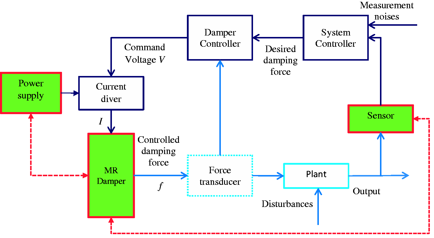
Shock absorber or magnetorheological damper’s vibration and shock create mechanical energy which might be used as energy sources and a huge amount of such mechanical energy is lost during daily usage. 16 External energy sources would not be required by transforming this wasted energy into electrical energy.17–19 Cho et al. 20 suggested an energy-generated magnetorheological damper that has an electromagnetic induction (EMI) device to generate energy. Their proposed model offers an innovative arrangement for self-powered vibration control but their enormous large size makes them inappropriate in little space application. Choi and Werely 21 developed a self-powered magnetorheological damper based on spring–mass electromagnetic introduction system. The generated energy was used as the source of magnetorheological damper to escape the use of extra power supply. However, their fixed control algorithm made them unsuitable for different applications. Moreover, Sapiński22,23 designed an EMI device known as energy harvesting device and proposed a system. To control the damping characteristics of the damper the energy generated from EMI was used. The performance, design and construction of the generator was the main focus of their research. Wang and Bai 24 proposed a system based on EMI, known as integrated relative displacement sensor technology to make magnetorheological dampers self-sensing. Their proposed model has an excitation coil around the piston head and an induction coil wounded on the non-magnetic cylinder. This new method cuts the application cost of the magnetorheological damper used but causes a slight reduction in the performance quality. Further, Sapiński 25 proposed an magnetorheological damper based on energy generation system. His proposed model has self-powered and self-sensing ability that eliminates the necessity of extra power supply and sensor. Nevertheless, the drawbacks of their model are the harvested voltage amount and heavyweight.
The goal of this paper is to design an energy harvesting magnetorheological damper which can decrease the used amount of electric power. The proposed magnetorheological damper has a permanent magnet and coil arrangement to generate energy and controllable damping technologies.
Design and modelling of the linear energy harvesting mono-tube magnetorheological damper
The proposed magnetorheological damper demonstrated in Figure 2(b) has both energy harvesting and damping (controllable damping force) part, whereas Figure 2(a) presents the traditional mono-tube magnetorheological damper. Wang and Bai
24
proposed model has an exciting coil which is wounded on the piston and the induction wire is coiled around the non-magnetic cylinder. This proposed model has additional permanent magnets in comparison with Wang and Bai’s model. The combination of permanent magnet and coil is used to generate power. The proposed model’s exciting coils are rounded on the piston head and the induction coil is wounded around the plastic cylinder. The plastic cylinder is attached to conventional magnetorheological damper’s outer cylinder wall whereas the permanent magnet attached to piston rod as shown in Figure 2(b). Among various design factors, damping performance (such as damping force, stress, etc.) is the key factor that means interaction issue. The performance of one should not be affected or influenced by another, particularly in time of piston movement. The proposed energy harvesting and the magnetorheological damper part have their own magnetic fields, which necessitates a special design for diminishing the magnetic field interference. It is necessary to reduce the dangerous cogging power which is produced from magnet and coil activity to generate controllable damping force. To fix this issue a mixed magnetic-field solitude method is suggested that effectively avoids the interactive area disturbance.
MR damper. (a) Traditional magnetorheological damper and (b) proposed energy harvesting magnetorheological damper. MR: magnetorheological.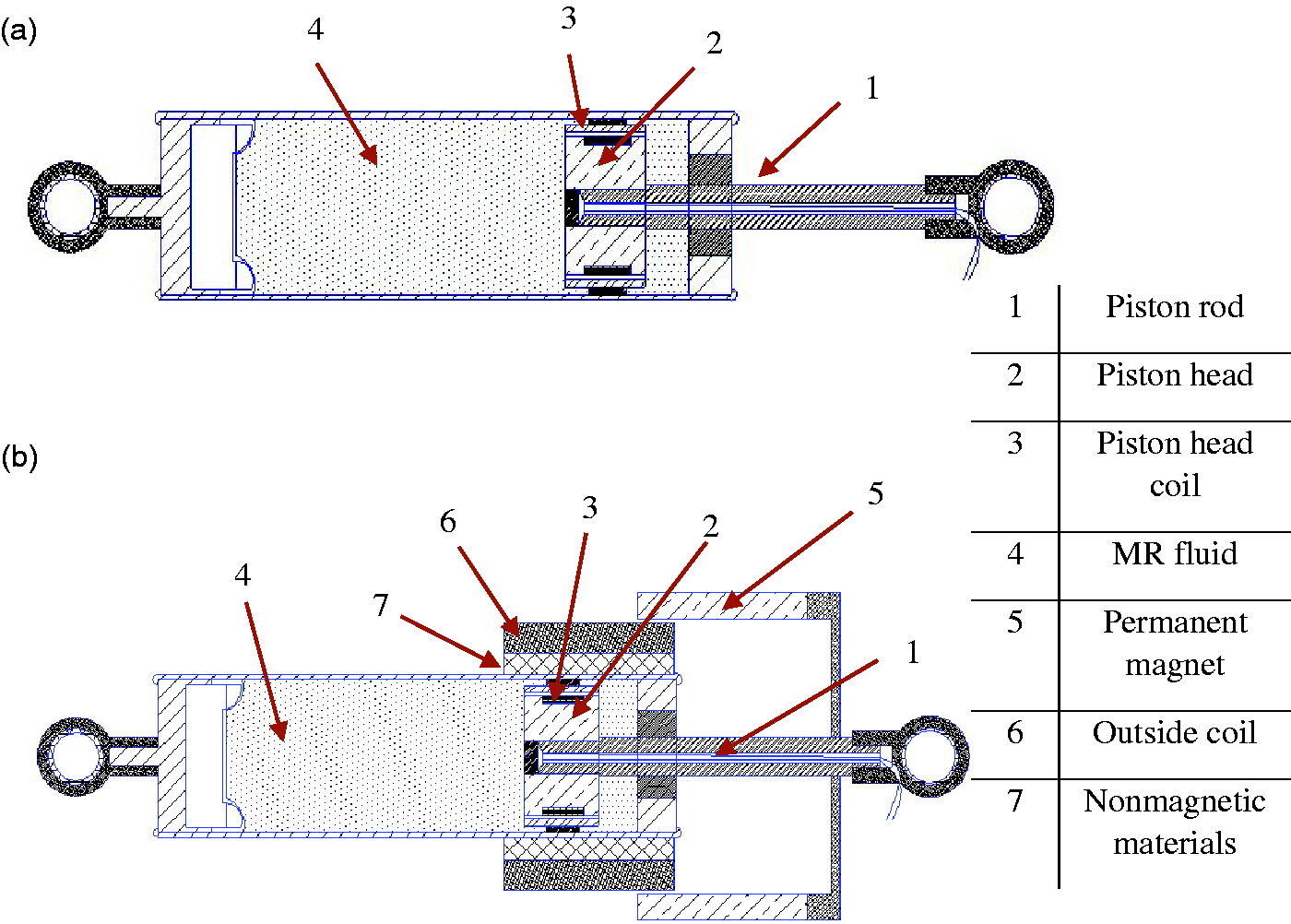
The energy harvesting part is another factor, where energy generation depends on working conditions of the magnetorheological dampers. Moreover, the input excitation of magnetorheological dampers is little in comparison with other energy harvesting systems. To fix this issue, permanent magnet and coil agreement is used to generate higher energy. This energy generator has higher power transformation ability along with magnetic flux of permanent magnet. The length of the proposed model is 168 mm with the stroke of around 40 mm and the diameter is 98 mm. There is a little air gap between the coil and permanent magnet, which helps the permanent magnet to move up to down in working condition. When the piston moves, the permanent magnet moves along with piston rod and the power generator’s coil cuts magnetic flux produced by the permanent magnet and harvests power. Figure 3 displays the flow graph of the proposed magnetorheological damper’s control system.
Schematic of the proposed model with magnetorheological damper.
26
MR: magnetorheological.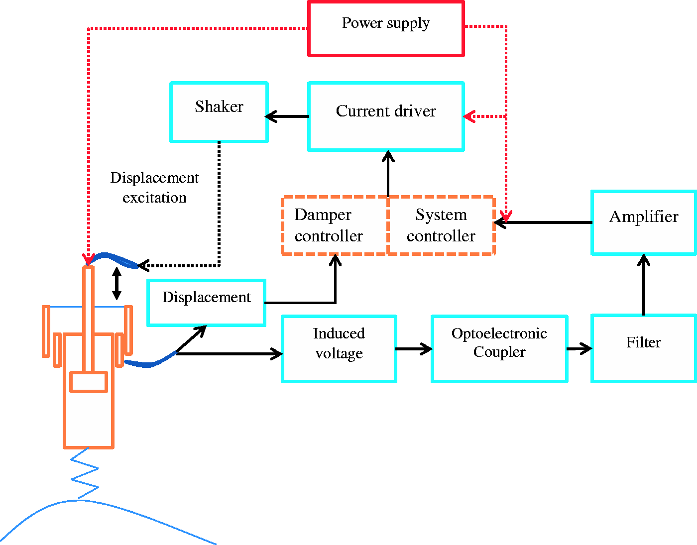
This generated voltage is connected to the control circuit and the control circuit is linked with the inner coil, thus capable of supplying current to the piston coil when it is necessary. Since the voltage generation depends on vehicle body vibration, the semi-active system has its own flexibility without the assistance of controller or corresponding sensors.
Modelling and analysis of proposed damper’s power generation ability

Specifications of the power generator.
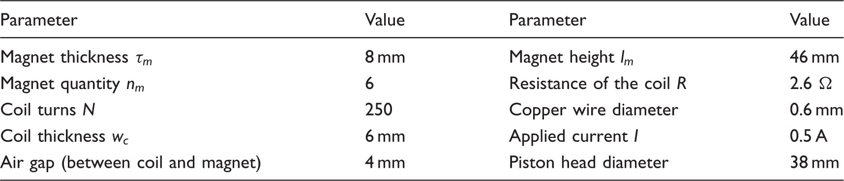
Here 
In dampers working condition, voltage is induced in damper’s power generator by utilizing mechanical vibration and supplied to the piston head coil in a controlled way and makes the damper self-powered. Figure 4 demonstrates the circuit that is powered by EMI where a coil with inductance L attached to a load resistor RL.
Schematic diagram of the circuit.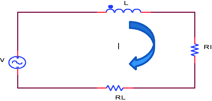
The following equation describes its behaviour by using Kirchoff’s voltage law
28


Damping force of the proposed magnetorheological damper
To characterize the damping performance of this proposed magnetorheological damper model in various working condition, the modified Bouc–Wen model is applied in this study. Figure 5 displays the improved Bouc–Wen model.
The modified Bouc–Wen model of the magnetorheological damper.
29
MR: magnetorheological.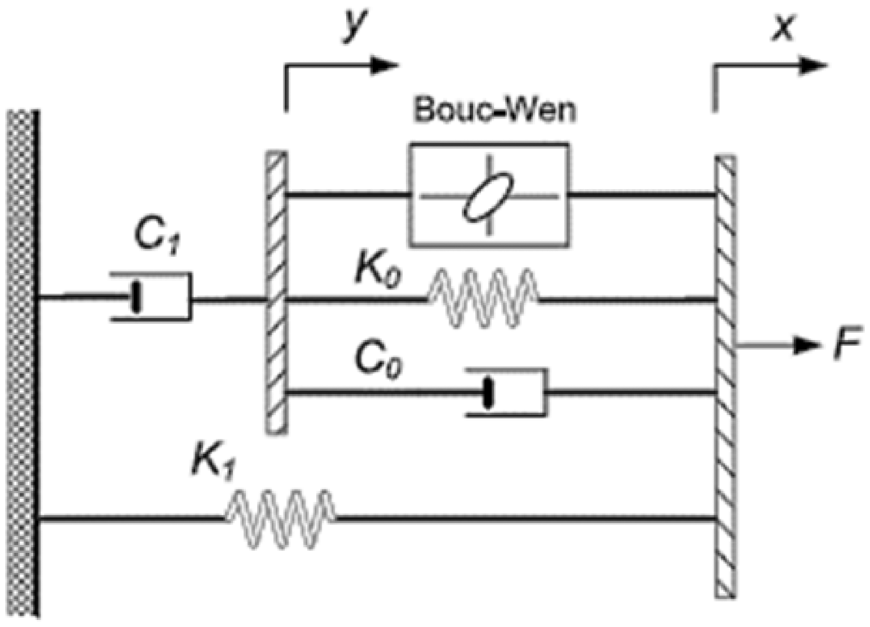
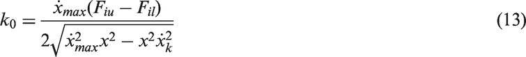
Here, k1 is the accumulator stiffness and c0 is viscous damping coefficient at larger velocities, c1 is the damping coefficient at low velocities. Moreover, k0 is the stiffness at larger velocities and x0 is the initial displacement of spring. In the improved Bouc–Wen model, the damping force of the magnetorheological damper is given as

The total force also might be written as


Numerical analysis of energy harvesting linear mono-tube magnetorheological damper
A 2D axisymmetric energy harvesting magnetorheological damper model is designed in COMSOL Multiphysics as shown in Figure 6(b). Figure 6(a) presents the cross-sectional view of the proposed 3D magnetorheological damper model. The piston head coil and magnetorheological fluid are considered in COMSOL model. The magnetic field provided by this piston head coil is important to stimulate the magnetorheological fluid. By varying current through the electrical coil the magnetic flux density can be varied and the magnetorheological fluid is energized accordingly. In COMSOL model, the current density is calculated by
(a) Three-dimensional cross-sectional view of the proposed magnetorheological damper model, (b) COMSOL 2D axisymmetric model for proposed magnetorheological damper and (c) mesh plotting of COMSOL model. MR: magnetorheological.
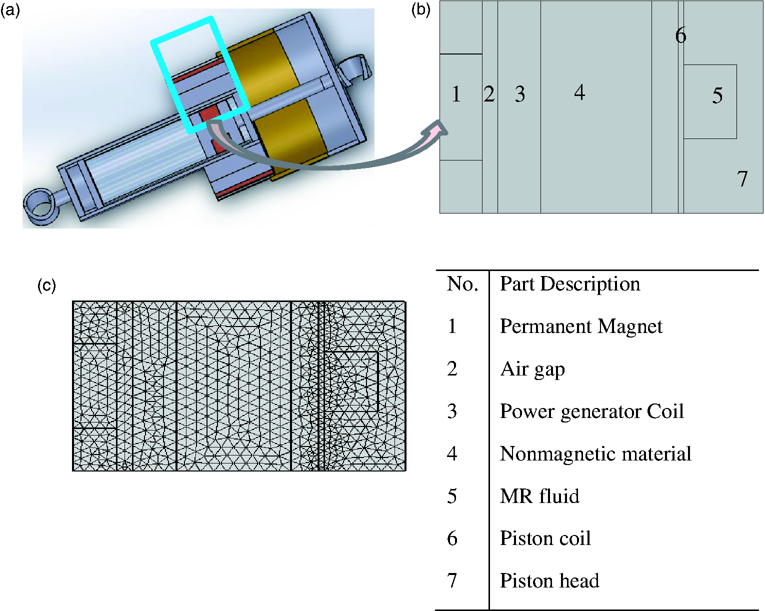
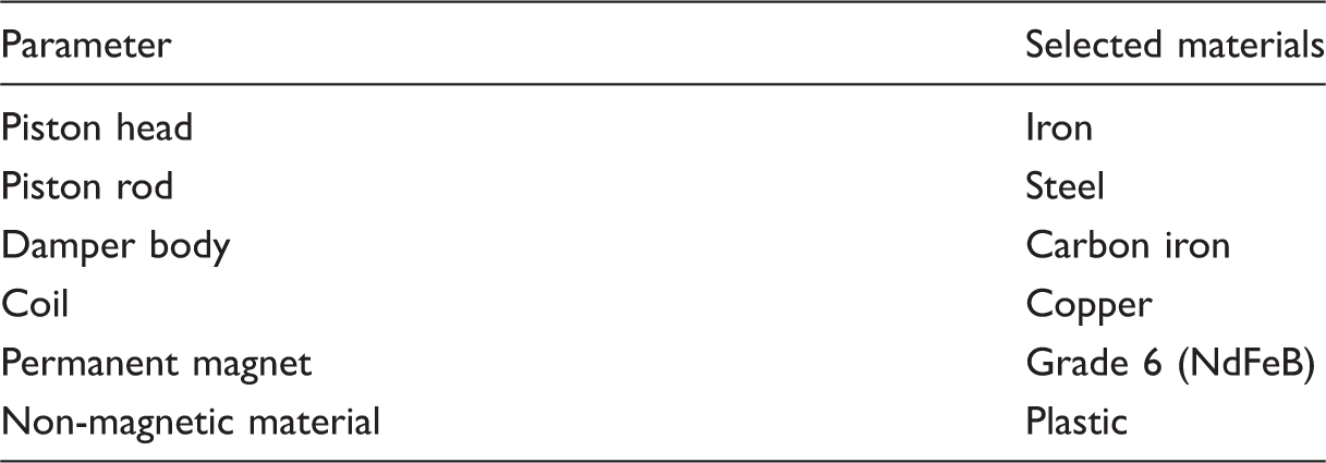
Selected materials.
In this research, COMSOL Multiphysics numerical analysis has focused on two major issues, such as the evaluation of power generation ability of the magnetorheological damper and another is the confirmation of absolute isolation between two magnetic fields induced by piston head coils and power generator of the model. This magnetic field isolation confirmation event is clearly expressed in both surface and contour plots of the energy harvesting magnetorheological damper model, which are exhibited in Figure 7.
Magnetic flux density (a) surface plot, (b) contour and surface plot, (c) contour plot only and (d) magnetic vector potential, phi component (contour plot only).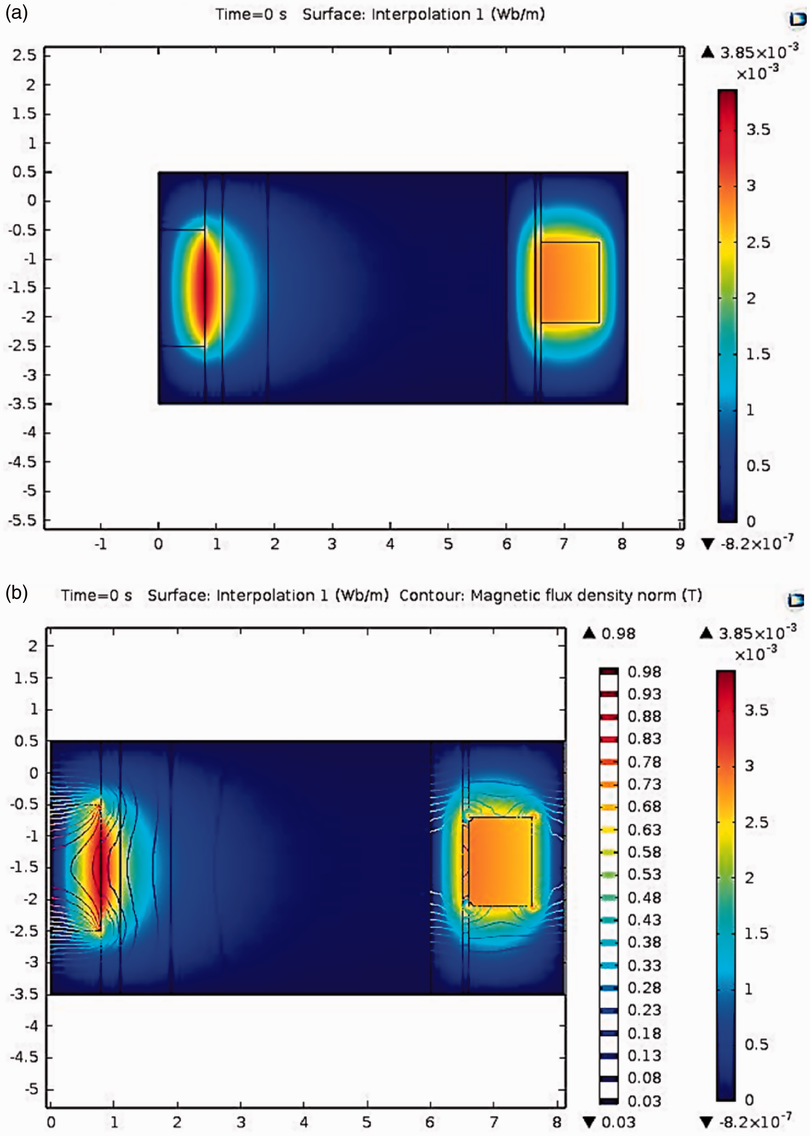
From Figure 7(a) and (b), it is investigated that the red colour variation represents the high magnetic flux density around the piston head’s coil area and permanent magnet area. Figure 7(c) and (d) presents the vector plot results that are observed by phi component where spreading magnetic flux density is easily analysed. In addition, Figure 7(c) and (b) clearly displays the magnetic flux density distribution around the piston coils and around the power generator coil area where there is no interaction among them. This magnetic flux density is zero inside plastic material which is situated between the damper’s outer wall and the power generator’s coil area. It signifies that magnetorheological fluid inside the damper is not affected by the flux of the outer power generator’s permanent magnet. These simulation results declare magnetic field isolation between the inner and outer magnetic field. Figure 8(a) and (b) exhibits the induced magnetic flux from the magnet. According to Faraday’s law, voltage will generate in the damper’s outer coil when these moving fluxes are cut by damper outer coil.
(a) Magnetic flux density norm (surface plot) and (b) magnetic flux density (magnetic vector potential, phi component) of the power generation part.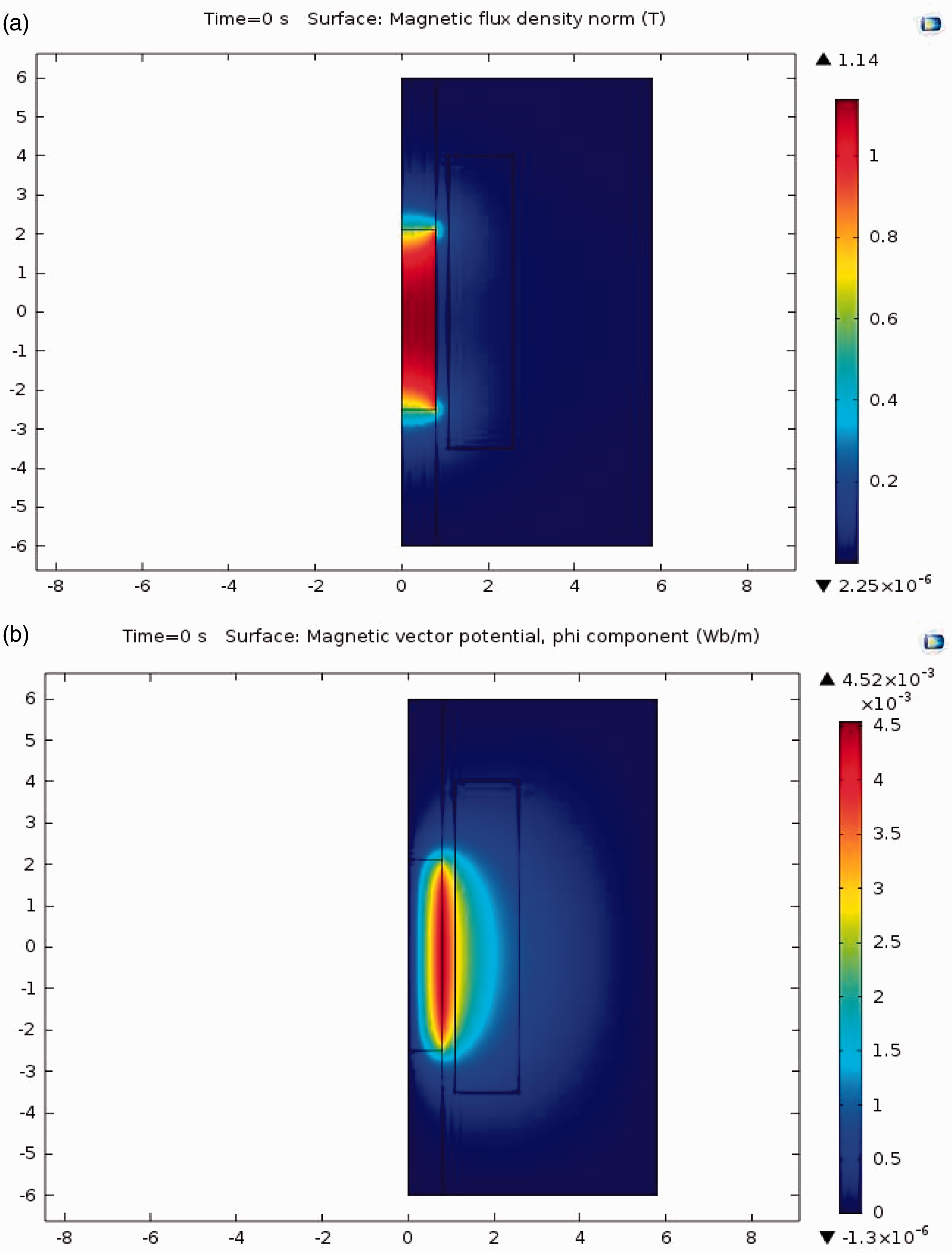
The red colour in Figure 8(a) and (b) presents the magnetic flux density of the power generator. The colour variation around the magnet area has proved that the higher magnetic flux density is produced around the magnet area. Figure 9 presents the magnetic flux density with vector plot of the energy harvesting part.
(a) Magnetic vector potential, phi component and (b) generated voltage from magnet and coil arrangement.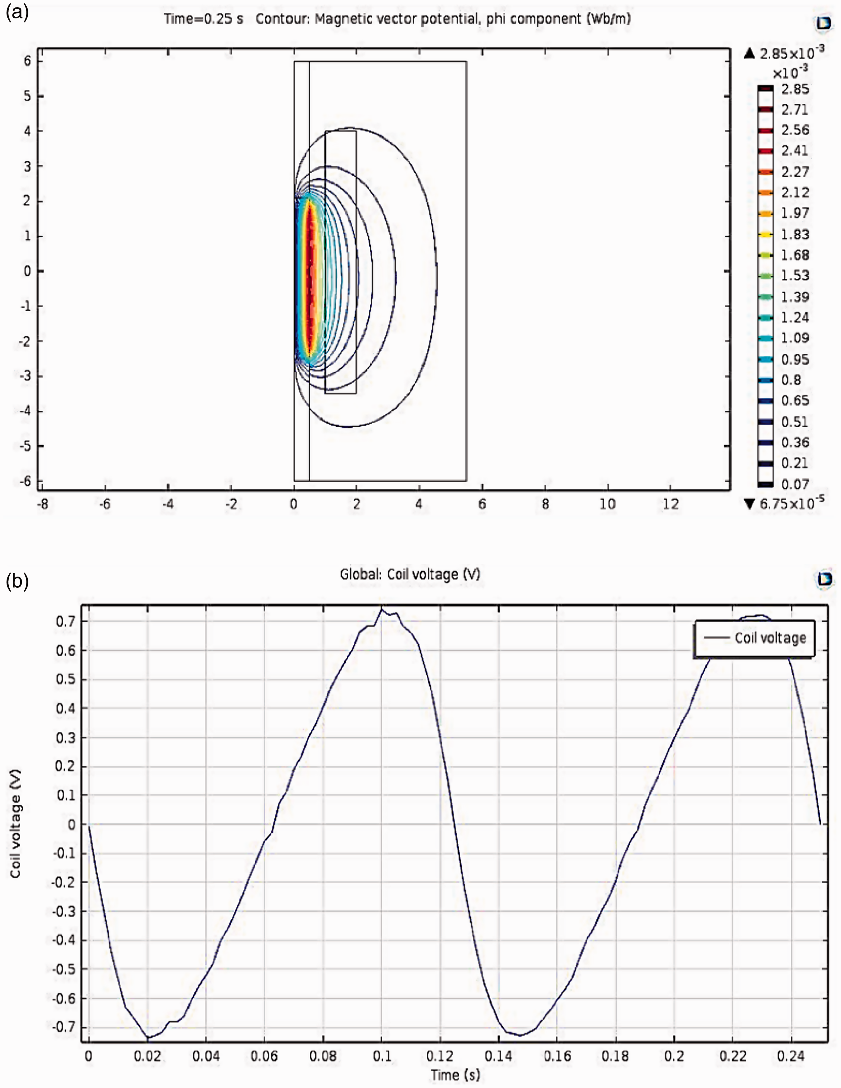
It is seen from Figure 9(a) that the magnetic fluxes are cut by the coil. With moving of magnet voltage generates inside the damper outer coil as shown in Figure 9(b), where the maximum induced coil voltage value is around 0.7 V.
Experimental analyses of the energy harvested mono-tube magnetorheological damper
Figure 10 shows the full experimental set-up which contains an magnetorheological damper, a current controller, an oscilloscope and universal testing machine (UTM) of Instron. To analyse the damping performance of the designed energy harvesting magnetorheological damper, force–displacement curves have been observed experimentally. magnetorheological damper’s piston rod was attached to the upper end of the UTM. The magnets move along with piston rod when the UTM machine moves linearly. An oscilloscope is used to measure the voltage induced in the coil.
Full experimental set-up of the proposed magnetorheological damper. MR: magnetorheological.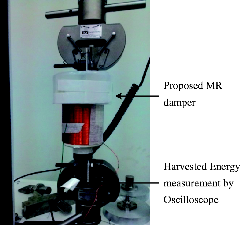
In this experiment, the piston’s stroke length has been maintained at 20 mm, stroke rate at 200 mm/min in case of both Lord and proposed energy harvested magnetorheological dampers. These curves are observed for six different excitation current of 0.0, 0.20, 0.40, 0.60, 0.80 and 1.0 A. Figure 11 represents the force and displacement relationship under different applied currents.
Force versus displacement relations of the magnetorheological damper with different applied current under 200 mm/min velocity, 20 mm displacement. MR: magnetorheological.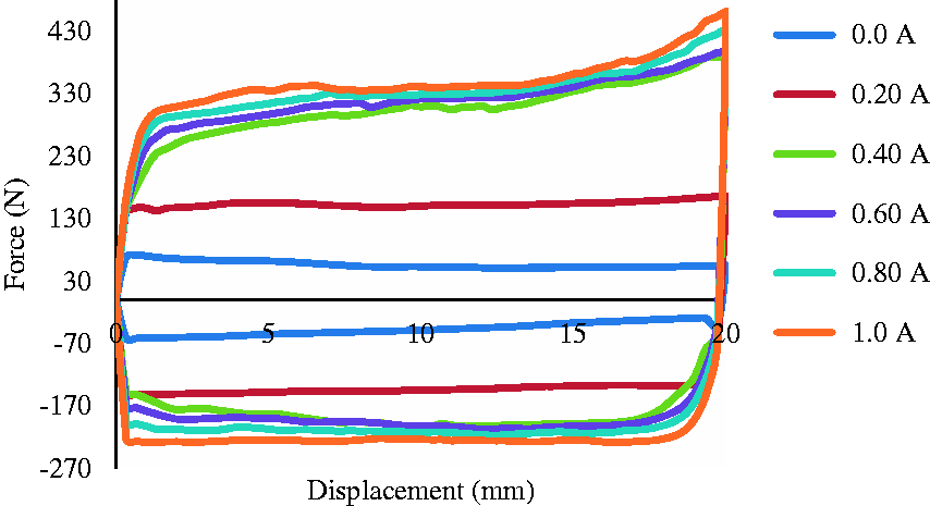
As demonstrated in Figure 11, without current supply the force and displacement loop is verging on circular. Further, it can be said from this figure that the damping force increases with the increment of applied current during same displacement rate. The damping force at 1.0 A is higher than the damping force at 0.0 A. That indicates that the ruffian vibratory vitality will increase as the applied current raises. Additionally, it is seen from Figure 11 that the force boosts from 70 to 480 N when the applied current is reached out from 0 to 1.0 A. Figure 12 shows the relation between force and time under velocity of 200 mm/min, with a displacement of 20 mm at altered applied current. The relation between displacement and time has been presented in Figure 13.
Force and time relations of the magnetorheological damper with different applied current under 200 mm/min velocity, 20 mm displacement. MR: magnetorheological. Relation between displacement and time.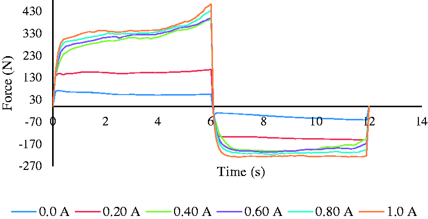
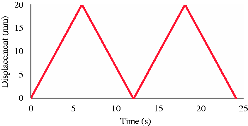
From Figure 12 it is realized that with a forward movement of time, the damping force increases with an increment in applied current. When time rises from 0 to 6 s then damping force surges from 0 to about 480 N with an applied current of 1 A. Moreover, it can be alleged from this figure that the backward damping force of the magnetorheological damper is lower than the forward damping force. Figure 13 exposes the relation between displacement and time. During forward stroke, the absolute value slope is higher than that of backward stroke. Figure 14 displays the relation between force and velocity for the same stroke length with an applied current of 0 A.
Damping force versus stroke length at different velocities.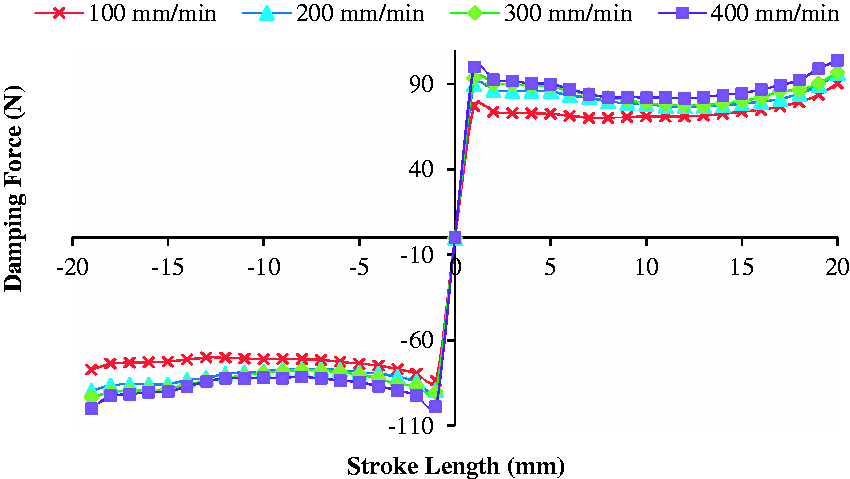


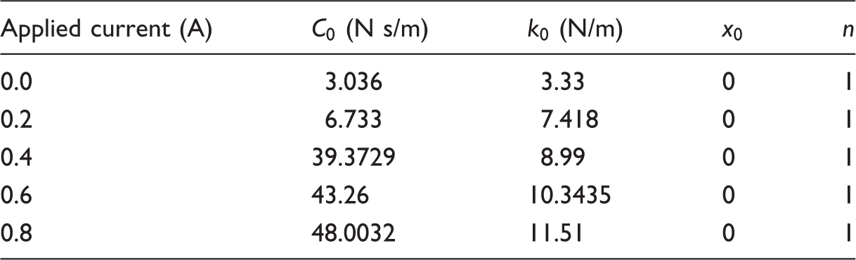
Values of the parameters for Bouc–Wen model.
The error is measured by utilizing equation (11) derived by Chen and Liao.
26
Equations (11) and (12) are used to identify the damping coefficient and spring stiffness.
30
In equation (12), Comparison of forces between established model and experimental results.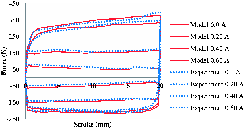
From Figure 15, an obvious observation is that the proposed magnetorheological damper’s damping forces are almost the same as the existing model. The dotted lines represent the experimental result (damping force) of the proposed magnetorheological damper under at varying currents and the solid lines show the forces for existing model. The magnets move along with magnetorheological damper’s piston rod and UTM moves linearly. During movement, flux induced by these magnets is cut by the dampers outside coil and generates a voltage which is measured by an oscilloscope. The voltage generated by the proposed magnetorheological damper is shown in Figures 16 to 19. Figures 16 and 17 demonstrate generated voltages by magnetorheological damper for 10 mm stroke length and Figures 18 and 19 illustrate the generated voltages for 20 mm stroke length. The generated voltage value depends on the excitation of the damper such as velocity, stroke length, etc. as displayed in Figure 20.
Induced voltage of the coil under 100 mm/min, 10 mm excitation. Induced voltage of the coil under 200 mm/min, 10 mm excitation. Voltage of the coil under 20 mm stroke with 100 mm/min velocity. Voltage of the coil under 20 mm stroke with 200 mm/min velocity. Relation between coil’s generated voltage and excitation of the damper.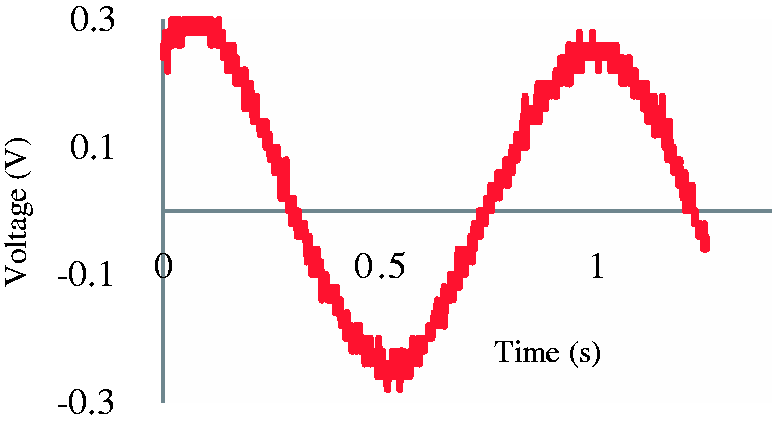
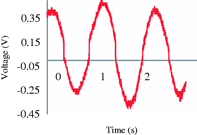
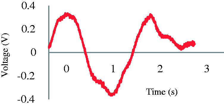
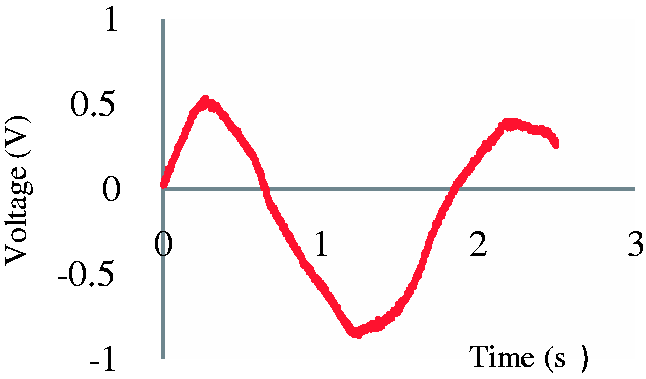
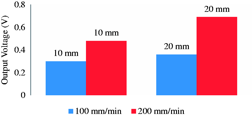
From Figure 20 it is realized that, with a stroke length of 10 mm and velocity of 100 mm/min, the output voltage is around 0.30 V; however, it increases to about 0.40 V at 200 mm/min velocity. The output voltage increases from around 0.46 V to around 0.58 V for 20 mm stroke length when velocity rises from 100 to 200 mm/min. Moreover, the generated voltage has relation with coil turn number and air gap, as shown in Figure 21.
Relation of generated voltage with coil turn numbers and air gap.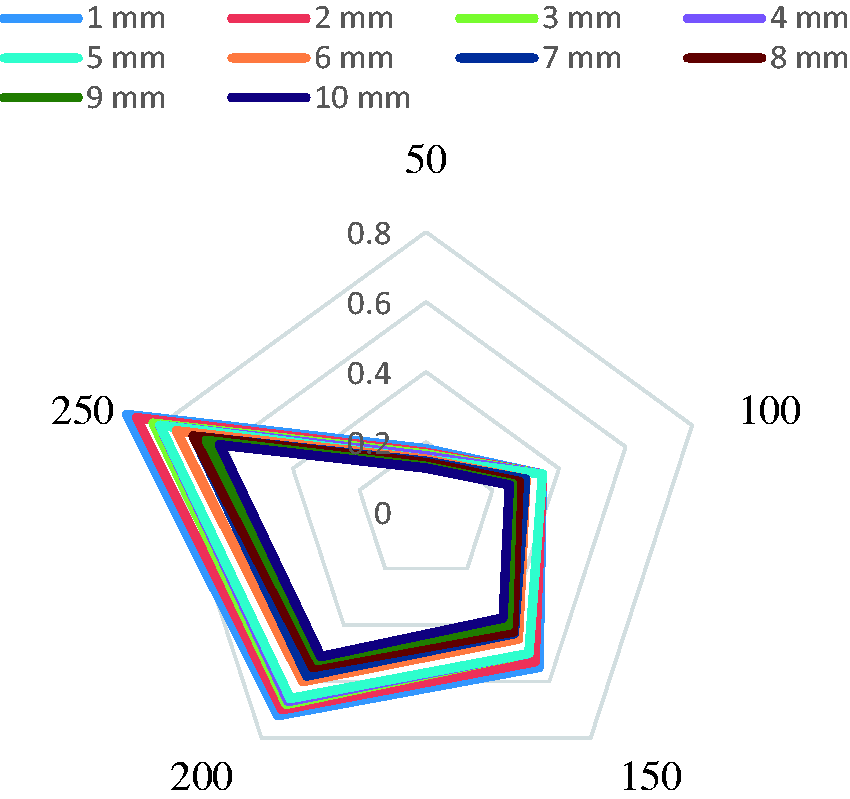
It can be said from Figure 21 that the generated voltage decreases with rising air gap but increases proportionally with increasing number of coil turns. Enlargement of air gap reduces the induced voltage; however, for a certain air gap, the generated voltage remains almost same which is known as optimize length.
Conclusion
In this study, an energy harvesting magnetorheological damper model has been analysed by both finite element simulation and experimentally which is capable of generating electric energy from mechanical vibration. Permanent magnets and coil arrangement is used as a power generator in this model. Finite element analysis has been accomplished broadly by COMSOL Multiphysics simulation software in order to characterize the model’s accuracy with the capability of energy generation. The contour and surface plot of power generator’s magnetic flux density confirms the simulation model’s energy harvesting capability. From the experimental investigation, an average induced voltage of magnitude 0.45 V is recorded in the oscilloscope from the power generator of the developed magnetorheological damper’s experimental model and the obtained result is almost close to simulation result. These result similarities validate the simulation model and the experimentally developed model’s power generation ability as well. The simulation results in Figure 7 visibly display the magnetic isolation between the two nearly situated magnetic fields. Further, in the experiment the power generator has no influence on the damping force value which declares the validation of developed model’s performance on magnetic field isolation.
Footnotes
Declaration of conflicting interests
The author(s) declared no potential conflicts of interest with respect to the research, authorship, and/or publication of this article.
Funding
The author(s) disclosed receipt of the following financial support for the research, authorship, and/or publication of this article: The authors would like to thank the Department of Mechatronics Engineering, International Islamic University Malaysia for giving the opportunity of using the material structure laboratory and Ministry of Higher Education Malaysia for funding the project FRGS/1/2014/TK03/UIAM/02/4.