
Abstract
Active control of harmonic sound transmission through an acoustically baffled, rectangular, simply supported double panel partition has been analytically studied. Velocity potential method is used for the vibro-acoustic modeling unlike the commonly used cavity mode method. It is very well-known that at high frequencies uncontrolled double panel partition mostly radiates sound due to the dipole-type motion of the radiating panel, which the volume velocity method can't be able to detect, therefore, weighted sum of spatial gradients is used to control these modes and achieves sound attenuation in a broad frequency band. A piezoceramic actuator (lead zirconate titanate) is attached on one side of the panel surface, and the optimal magnitude and phase of the voltage supplied to the lead zirconate titanate for minimizing the weighted sum of spatial gradients and volume velocity at the error sensor locations are calculated using a simple-gradient based algorithm. Numerical results of sound power transmission ratio and averaged quadratic velocity of panels indicate that lead zirconate titanate should be placed on the incident panel and minimization of the control quantities should be done on the radiating panel to achieve better sound attenuation. The acoustic radiation mode analysis shows that the weighted sum of spatial gradients is able to control multiple acoustic radiation modes and, thereby, accomplishes better reduction of sound power transmission compared to volume velocity.
Motivation and background
Double-wall structures are widely used in noise control engineering due to their superiority over single-leaf structures in providing better acoustic insulation. Typical examples include vehicles, partition walls in buildings and aircraft fuselage shells, etc. However, the acoustical properties of these structures are less desirable at low frequencies, which can lead to high noise levels. Therefore, new means of providing noise attenuation at low frequencies need to be established.
Sound absorption materials in the cavity fail to provide enough absorption in the low frequency range because acoustic wavelengths are much longer than the dimension of damping materials.1,2 As an alternative method, active control techniques have been explored to increase the sound transmission loss (STL) of these kind of structures.3–6
Active control of sound methods is generally classified into two categories. The first one is active noise control (ANC).7–9 In this approach, loudspeakers are used as secondary sources to generate antiphase signal for the cancellation of the primary sound field. The other one is the active structural acoustic control (ASAC) technique in which the sound radiated by structures is controlled using one or several control actuators applied directly on the vibrating structures.10–13 The benefits of ASAC over ANC are associated with the control of sound at the source and the system compactness. Structurally applied actuators are much less intrusive than speakers because they do not use space in the acoustic field.
ASAC is very effective in controlling sound pressure.14–16 However, the main issue with ASAC is in determining the objective function, which will provide the best global acoustic attenuation. It has been seen that use of vibration modes, which are generally used in vibration analysis and control, 17 cause some difficulties in sound radiation analysis. 18 In general, there are two primary mechanisms for minimization of sound power radiation in ASAC. 19 One is “modal suppression (modal control)” and the other is “modal restructuring (modal rearrangement).” Modal control method usually increases the impedance at the structural modes and thus decreases their amplitudes. This is very effective where the structural response is dominated by one or a small number of modes. However, modal suppression technique alters the amplitudes and phases of the structural modes, and thereby, either reduces the overall vibration level of the structure or creates vibration patterns which radiate less efficiently.
Therefore, the acoustical or radiation modes, which radiate sound power independently and whose control gives guarantee to the attenuation of sound power, have been developed. 20 The shape of the first radiation mode is comparable to volume velocity and it has been suggested that using an error sensor to measure volume velocity on the plate would be an effective way to control the radiated sound power. It has been found that the volume velocity control strategy is able to attenuate large amount of sound power.21,22 However, this strategy is less effective at higher frequencies because of the number of sensors required for reasonable attenuation, in many situations, is too large for practical purposes.23–26 A recent control metric, termed composite velocity (also referred to as weighted sum of spatial gradients or WSSG) has shown promise in resolving these issues. Composite velocity was developed as a weighted sum of spatial velocity gradients requiring only four sensors to measure, and was found to be relatively insensitive to sensor location.27,28 Hendricks et al. 29 extended this research from computer simulations and provided experimental test results for a flat simply supported plate.
Considerable efforts have been devoted to understand and control the sound transmission actively through the double panel partitions.30–34 For instance, Henrioulle et al. 31 designed a distributed acoustic actuator made of a piezoelectric PVDF film to control the sound transmission through a double panel partition. Simulation results show that a substantial increase of transmission loss is achieved in the low frequency region. Sound transmission through finite double panels using lead zirconate titanate (PZT) ceramic sensors and actuators was investigated by Lhuillier et al. 33 Active control of sound transmitted through a double-leaf partition by cancelling the volume velocity of the radiating panel was proposed by Pan et al. 34 They found that the double-leaf construction provides good passive attenuation of the first radiation mode at high frequencies; however, it couldn't be able to control the even modes of the radiating panel, which make a dominant contribution to the radiated sound power and, thus, there is no advantage in controlling volume velocity in the high frequency region. In most of these studies, hard-walled cavity modal function is used to model the sound field in the cavity. In practice, the rigid baffle bounds the cavity as well as the panel, so that the cavity boundaries restrict the field to be of sinusoidal distributions parallel to the panel plane and, therefore, sound velocity potential method35–38 is recently proposed.
The aim of this article is to study the transmitted sound power attenuation through a double panel system by targeting multiple acoustic radiation modes, so that the dipole-type of motion of double panel systems at high frequencies can be controlled, and hence, sound attenuation in a large frequency band can be accomplished. Pan et al. 34 found that to attenuate sound power in a large frequency band, active structural control of second and third sound radiation modes need to be considered. In the present study, this facet is taken into consideration, and the more commonly used cavity modal method 34 is replaced by the velocity potential method 38 because cavity modal method deviates from the precise results when the cavity is bounded by two large flexural panels. WSSG control strategy is used to control multiple sound radiation modes unlike the volume velocity control strategy which targets only the first radiation mode. For completeness of the study, the effect of air cavity thickness and the angle of incidence of the incident sound wave on the controlled radiated sound power are also investigated.
Modeling
Structural-acoustics coupled modeling
Consider a double panel system as shown in Figure 1. A harmonic plane wave is incident on the top surface of panels 1 and 2 is attached to a piezoceramic (PZT) patch. It is assumed that both the panels are isotropic, flat and simply supported on all four edges. And, all sides of the cavity are considered as hard boundaries except the two panels (panels 1 and 2) which are flexible. Therefore, instead of the hard-walled cavity modal function, which can only accurately model the sound field in a rigidly bounded cavity volume; in the present work, velocity potential method is adopted.
38
Schematic of a double panel partition in which panel 1 is excited by a plane wave and a PZT is attached on panel 2: (a) global view, (b) top view, and (c) side view in the direction of arrow shown in (a).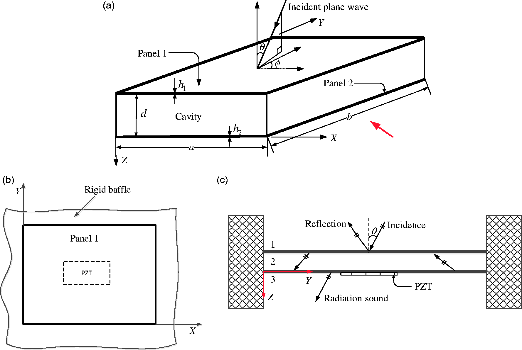
Following the velocity potential approach,
38
acoustic velocity potential for an obliquely incident uniform plane sound wave varying harmonically in time can be expressed as,

Using the small deflection theory of panels based on the classical plate theory, the governing equations of motion are found by extending the work done by Xin et al.
38
with a PZT on panel 2 as follows:


Considering the double panel partition as rectangular and simply supported, the transverse displacement and transverse force of each panel are constrained to be zero along the edges, and hence, the boundary conditions can be expressed as,


Since the normal velocity is continuous at the air-panel interface, compatibility equations are given by,


If the structural vibration is assumed to be described by the summation of M modes and both the panels are simply supported, the forced response can be expanded in terms of normal modes as,
19


As the rigid baffle bounds the cavity as well as the panel, the cavity boundaries restrict the field to be of sinusoidal distributions parallel to the panel plane. Therefore, the velocity potentials can be expressed in terms of the panel modal functions as,
38


Substituting equations (14)–(16) into equations (10) and (11) with some algebraic manipulations results in


The substitution of equations (12) and (18)–(21) into equations (2) and (3), and omitting the co-ordinate axis and the summation sign in the interest of brevity, one obtains


The sound power transmission ratio is a function of the elevation angle θ and azimuthal angle φ of the incidence sound and can be expressed as,
38

Two parameters, related to the vibration of panels and the acoustic field, are defined as follows:
38
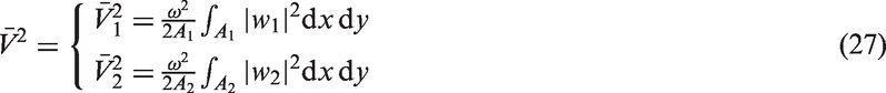
Average quadratic velocity of panels 1 and 2 are
Average quadratic sound pressure

Here, p is the acoustic pressure along a plane inside the cavity and the quadratic sound pressure is expressed in dB referenced to
Radiation of sound power from a vibrating panel
Some of the results quoted in the following sections will be expressed in terms of the radiated sound power level from the acoustic radiation modes of the radiating panel, i.e. panel 2, which has been calculated by the elemental radiator formulation approach.
20
In this formulation, the panel is divided into a grid of D elements whose transverse vibrations are specified in terms of the velocities

Therefore, the total radiated sound power can be defined as
Acoustic radiation mode shapes.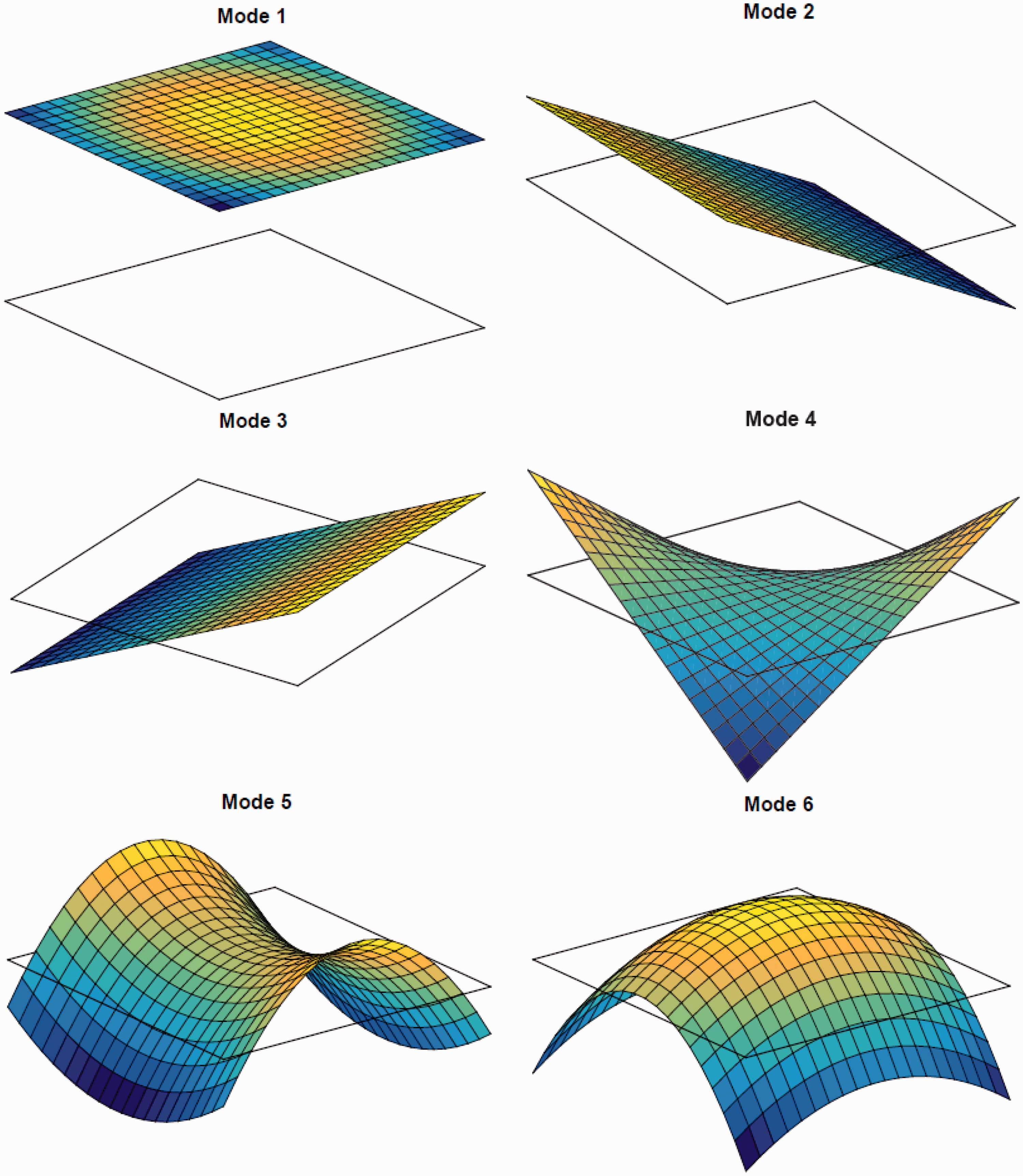

Equation (30) can be rewritten as

Formulation of panel volume velocity
Volume velocity of a panel can be determined by the summation of the product of velocity and the corresponding elemental area of each element where the volume velocity sensors are located. Therefore, the volume velocity of each element where the volume velocity sensors are located can be written as,21–23

Formulation of WSSG
The minimization of WSSG will be tested as a strategy for controlling the sound power radiation and compared with the results from volume velocity. WSSG of a structure is simply the sum of scaling values multiplied with the square of transverse velocity, rocking velocity in X and Y directions, and twisting velocity and is given by,27,28

Numerical results and discussions
Material properties of panels, PZT, and air.
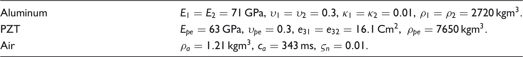
It can be seen from the figures below that most of the sound is radiated at (odd,odd) modes and the largest peak occurs near to (1,3) structural mode, i.e. near to 220 Hz, therefore, a PZT of dimensions
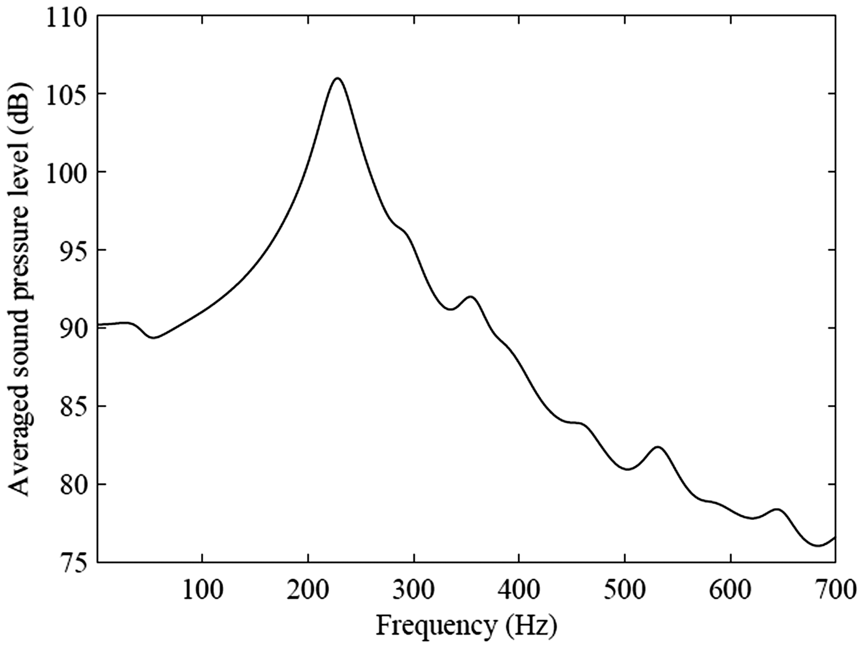
Figures 3 and 4 show the spectra of the averaged quadratic velocity level of the two panels and averaged sound pressure level in the cavity, respectively. The vibration energy of the incident panel and the radiating panel (as reflected by the averaged quadratic velocity level, Figure 3) is more or less same at the first two modal frequencies, that is, (1,1) and (1,3) modes, however, after that vibration velocity of panel 2 reduces rapidly as compared to panel 1, which demonstrates that vibro-acoustics coupling effect further weakens at high frequency region, inducing less energy transmitting in the air cavity. It can be seen from Figure 4 that the sound pressure in the air cavity near to (1,3) panel mode, that is, at around 220 Hz is very high which very well agrees with the quadratic velocity level shown in Figure 3.
Averaged quadratic velocity of panels 1 and 2. Averaged quadratic sound pressure at the middle of the air cavity.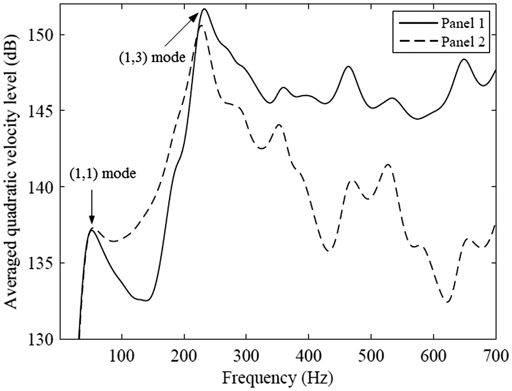
In order to demonstrate the effectiveness of the control strategies, PZT is placed at different locations of the double panel partition. Figure 5 represents the simulated sound power transmission ratio with and without the minimization of volume velocity and WSSG of either on the incident panel (panel 1) or the radiating panel (panel 2) while driving a PZT on panel 1. While minimizing volume velocity and WSSG of panel 2, the first two modal peaks, (1,1) and (1,3) modes, are convincingly controlled by both the control strategies, however, after that WSSG out performs volume velocity by transmitting less sound power in most of the frequency range because WSSG has the ability to control multiple acoustic radiation modes as compared to the first acoustic radiation mode what volume velocity targets and hence, the STL in WSSG is 6.2 dB whereas for volume velocity it is 3.8 dB. On the other hand, application of the control strategies on the incident panel does not provide better sound attenuation as compared to the minimization of the same on the radiating panel.
Sound power transmission ratio by driving a PZT on panel 1. Key:  No control;
  minimizing volume velocity of panel 1;
  minimizing volume velocity of panel 2;
  minimizing WSSG of panel 1;
  minimizing WSSG of panel 2.
PZT is attached to panel 2 to minimize the volume velocity and WSSG of the same or panel 1, and sound power transmission ratio has been calculated using equation (26) and shown in Figure 6. It can be observed that minimization of WSSG on panel 1 (incident panel) delivers better sound attenuation near to (1,3) structural mode, however, after that the power transmission ratio goes on increasing. But minimizing WSSG on panel 2 (radiating panel) provides better sound reduction till 550 Hz, and therefore, there is a sound attenuation of 3 dB occurs. Similar trend can be seen for volume velocity control method. However, the sound power transmission ratio is more than one while minimizing the volume velocity of the radiating panel, that is, the radiated sound power is more than the incident sound power, and hence, there is an increase of 4.7 dB in the sound power radiation takes place.
Sound power transmission ratio by driving a PZT on panel 2. Key: as for Figure 5.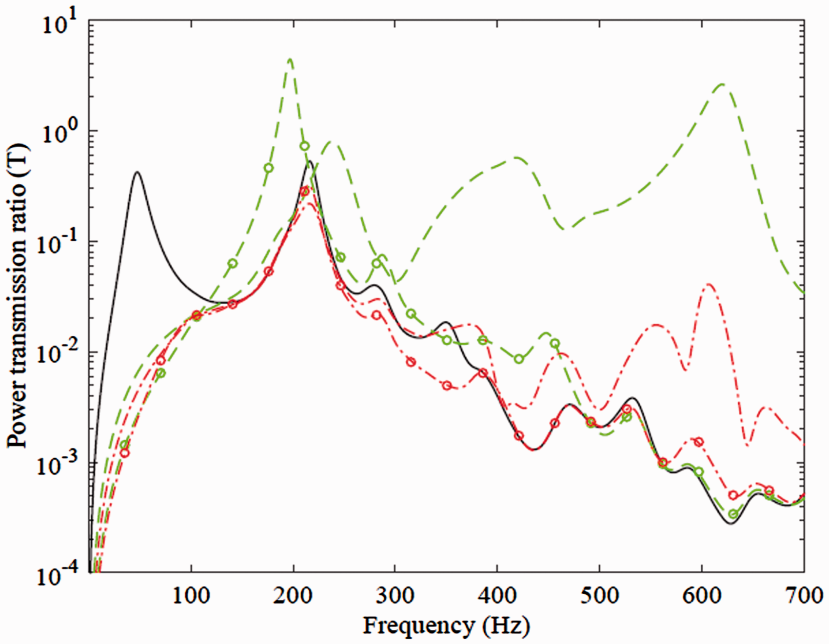
Now to further examine the effectiveness of the control strategies, one PZT is attached at the center of each panel to minimize the WSSG and volume velocity of the incident panel (panel 1) or the radiating panel (panel 2), and the sound power transmission ratio is plotted in Figure 7. It can be seen from this figure that the implementation of the control strategies on the incident panel offers worst sound attenuation. However, while applying the active control methods on the radiating panel, both the control methods attenuate the first modal peak but not convincingly as in Figures 5 and 6, nonetheless, (1,3) mode is controlled better as compared to the previous two cases. From Figures 5 and 6, it can be observed that the sound attenuation at (1,3) mode (second peak) in Figure 6 is more as compared to Figure 5, while minimizing the WSSG on panel 1. And the reverse is true while minimizing the WSSG on panel 2. The reason for this is that there is no control on panel 2 (radiating panel) while applying both the WSSG and PZT on panel 1. Also the actuator driven by volume velocity method excites the radiating panel near to the first mode and at 475 Hz to increase the overall sound transmission by 0.6 dB. On the other hand, WSSG attenuate 3.6 dB of overall radiated sound power.
Sound power transmission ratio by driving a PZT on both the panels 1 and 2. Key: as for Figure 5.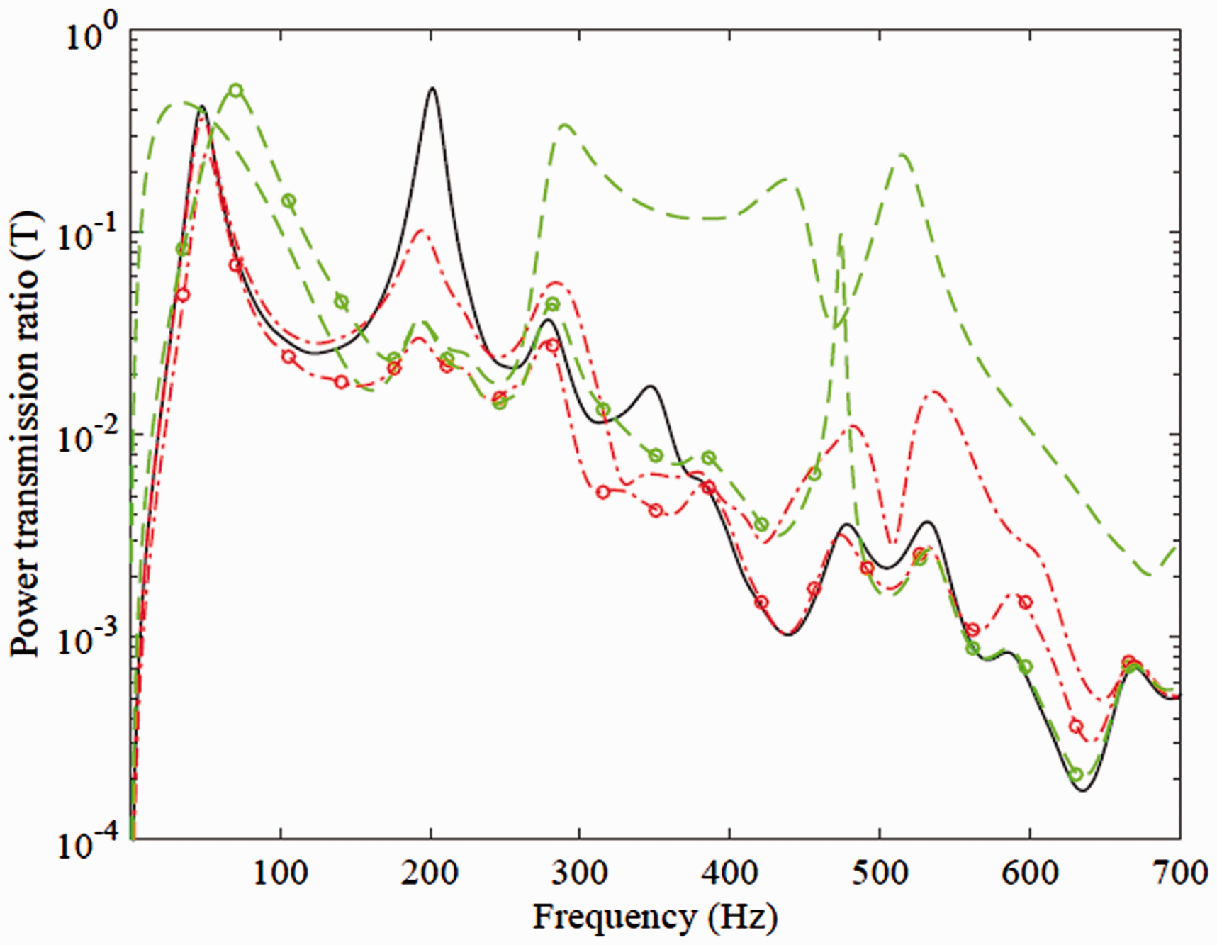
It can be concluded that minimization of the control quantities on the radiating panel (panel 2) offers better sound attenuation. Also, WSSG works exceptionally well as compared to the volume velocity control metric by targeting multiple sound radiation modes. Best attenuation of sound power is achieved by driving the PZT on panel 1 and worst on placing the PZT on panel 2, which very well agrees with the findings by Pan et al. 34 The reason could be associated with the fact that the quadratic velocity of panel 1 (Figure 3) is high as compared to the panel 2 in the high frequency region and hence, driving a PZT on panel 1 obtains better result till 550 Hz. It should be pointed out here that that the maximum increase in power transmission ratio is less in WSSG control than for volume velocity method. This is an important feature for cases where the structural excitation is narrowband in nature, which is in good agreement with Fisher et al. 27
Since it has been concluded that minimization of the control quantities on the radiating panel while placing the PZT on panel 1 achieves the best result, therefore, to save space, in the remaining study, only this configuration is further investigated.
Active control at high frequencies
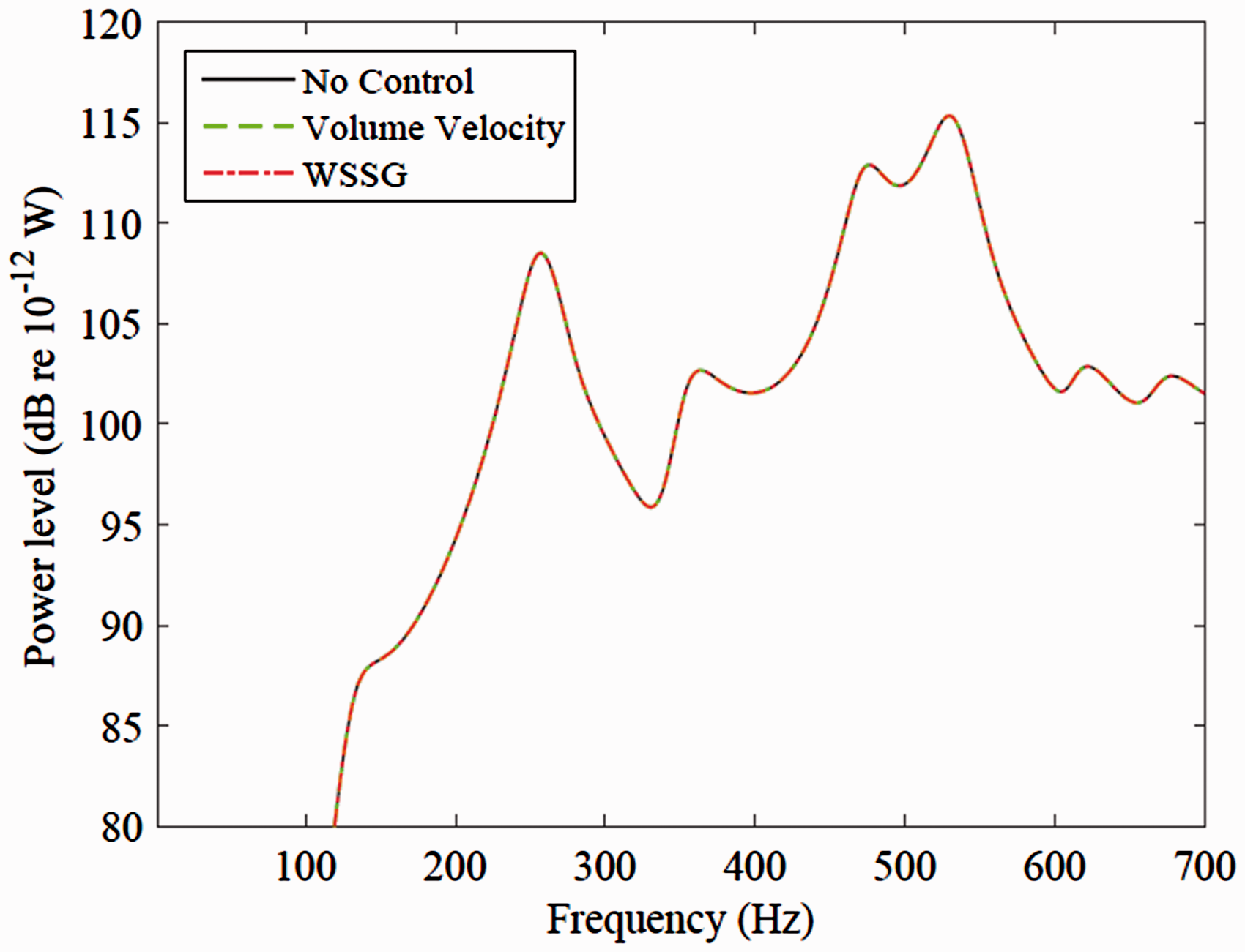
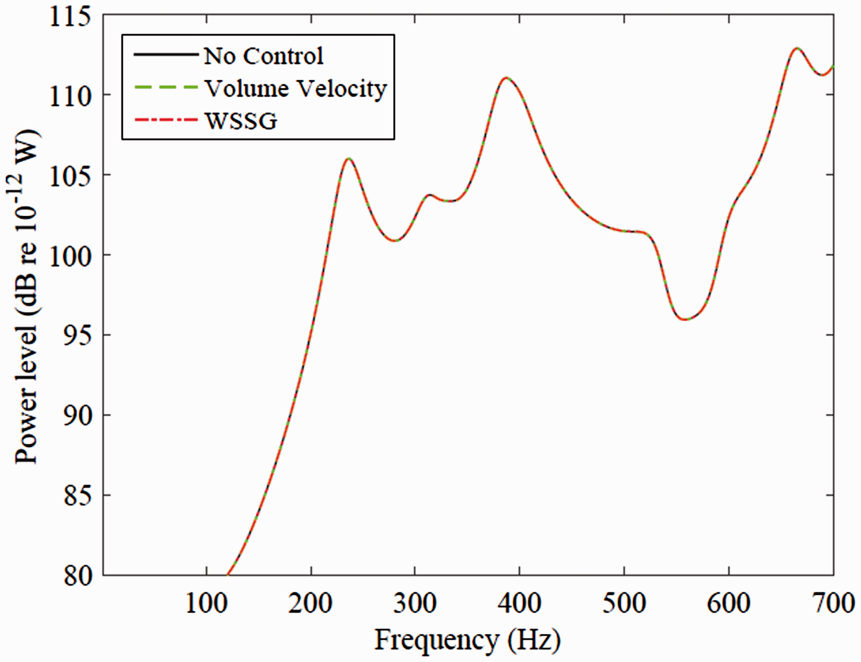
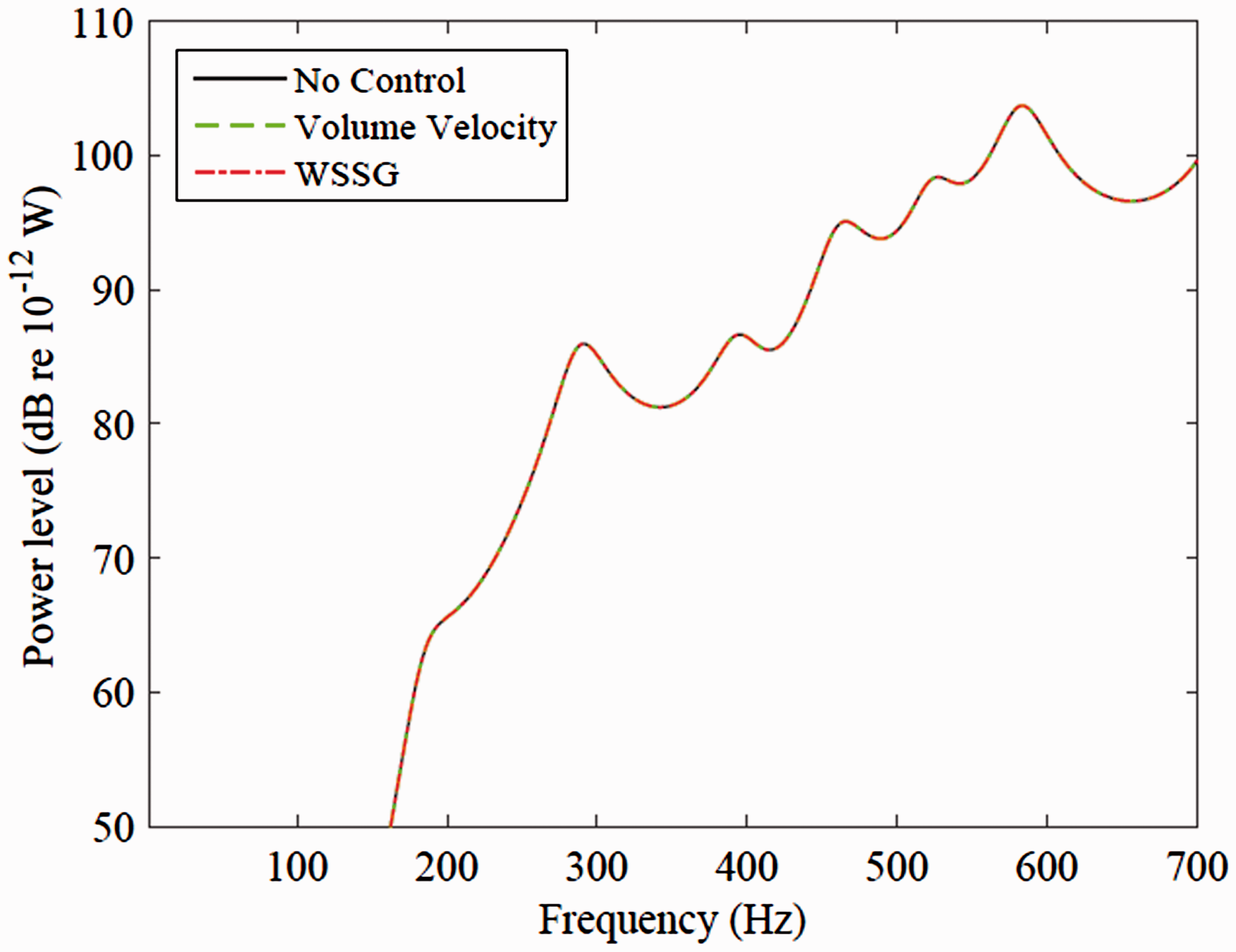
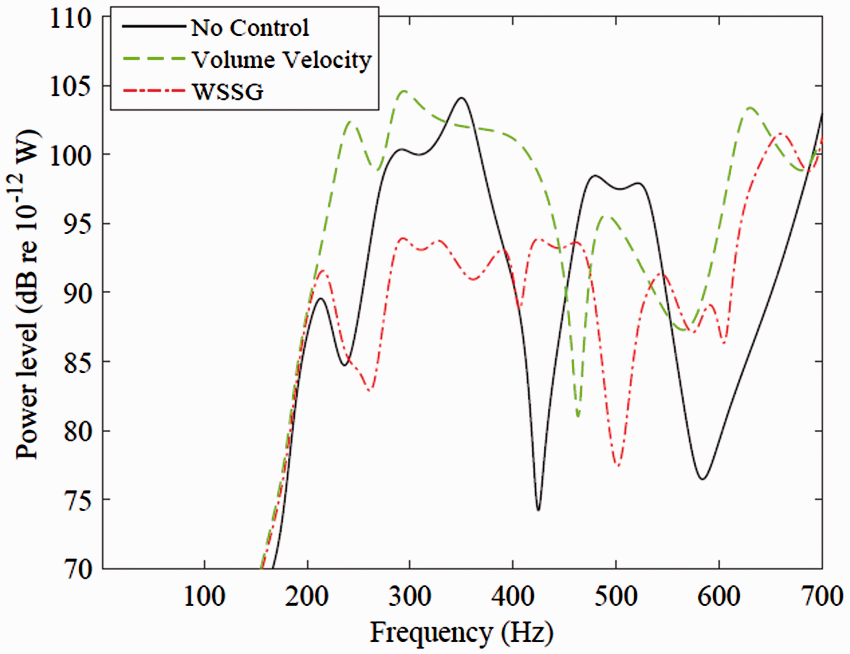
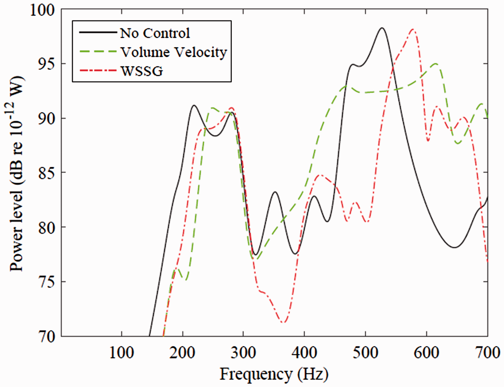
It is quite evident from Figures 5–7 that the volume velocity works well in the low frequency region, however, it is unable to perform like the WSSG, which attenuates sound convincingly till 550 Hz. In order to explain this, radiated power at the first six radiation modes (Figure 2) are determined and shown in Figures 8–13. At first radiation mode, volume velocity strategy works exceptionally well as compared to the WSSG in the whole frequency range considered here. Since the PZT is placed exactly at the center, none of the methods able to alter the radiated power level at second (Figure 9), third (Figure 10), and fourth (Figure 11) radiation modes and hence the solid, dashed, and dashed-dot lines coincide with each other. The reason of this can be understood by looking at the radiation mode shapes shown in Figure 2 (especially the radiation mode shapes at modes 2, 3, and 4), from which it is very evident that by placing an actuator in the middle, there can't be any change in the radiation behavior of the panel. However, at fifth (Figure 12) and sixth (Figure 13) radiation modes, WSSG out performs the volume velocity method to control large amount of transmitted sound power. Since, WSSG has the ability to control multiple acoustic radiation modes, and therefore, it controls the sound power significantly till 550 Hz.
Radiated power from the first acoustic radiation mode by driving a PZT on panel 1. Radiated power from the second acoustic radiation mode by driving a PZT on panel 1. Radiated power from the third acoustic radiation mode by driving a PZT on panel 1. Radiated power from the fourth acoustic radiation mode by driving a PZT on panel 1. Radiated power from the fifth acoustic radiation mode by driving a PZT on panel 1. Radiated power from the sixth acoustic radiation mode by driving a PZT on panel 1.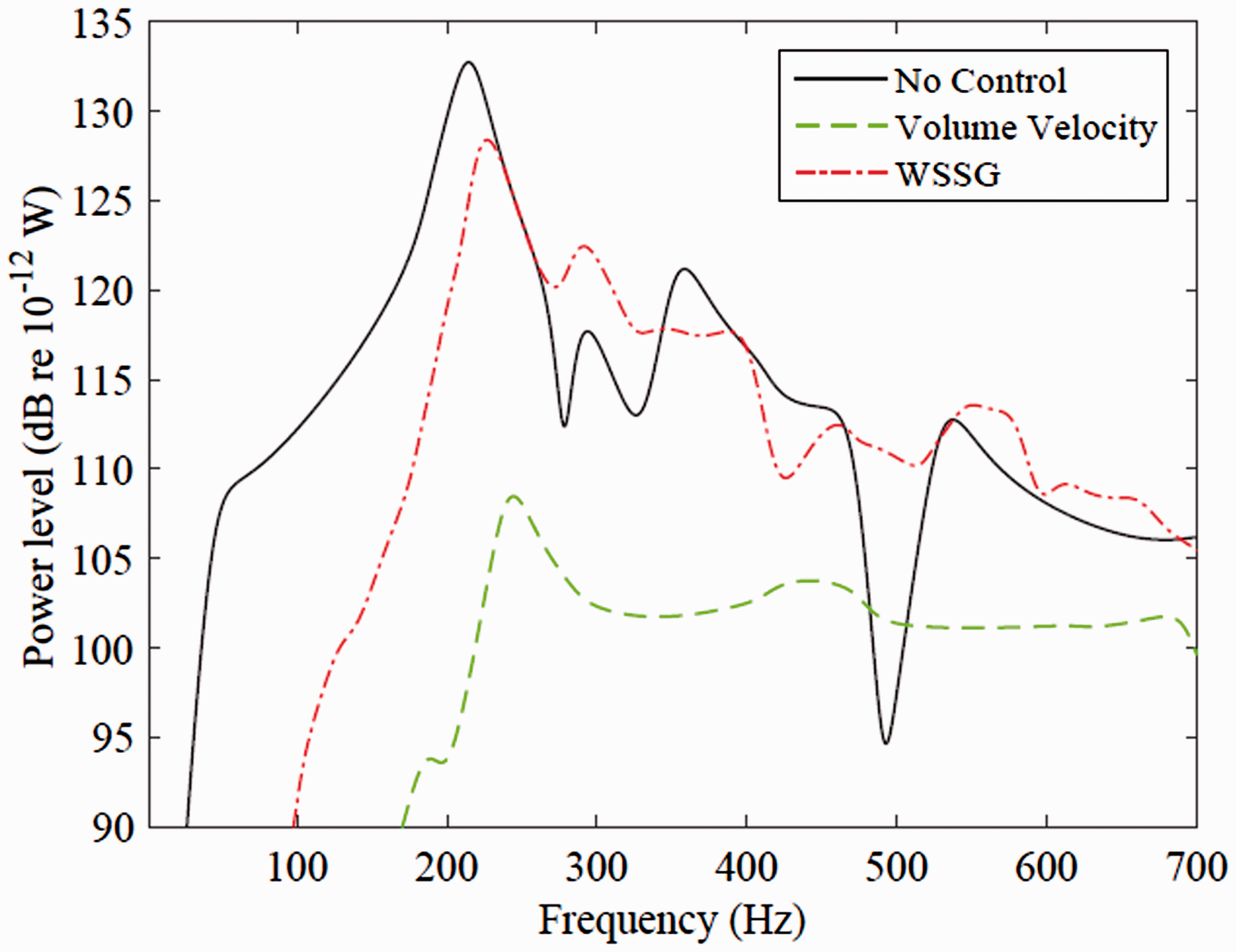
Effects of air cavity thickness
The air cavity inside a double panel partition acts as springs, and hence, transmits the mechanical vibration from the incident panel to the radiating panel and vice-versa to facilitate the sound transmission in a double panel partition system. Therefore, it is of interest to study the effect of cavity thickness before and after the implementation of control strategies. As it has already been concluded that WSSG works better than volume velocity, therefore, to save space, only WSSG control method is considered in the below investigation. By keeping the geometrical and material properties fixed other than the air cavity thickness for three selected values, i.e. Effect of cavity thickness on sound power transmission ratio by driving a PZT on panel 1.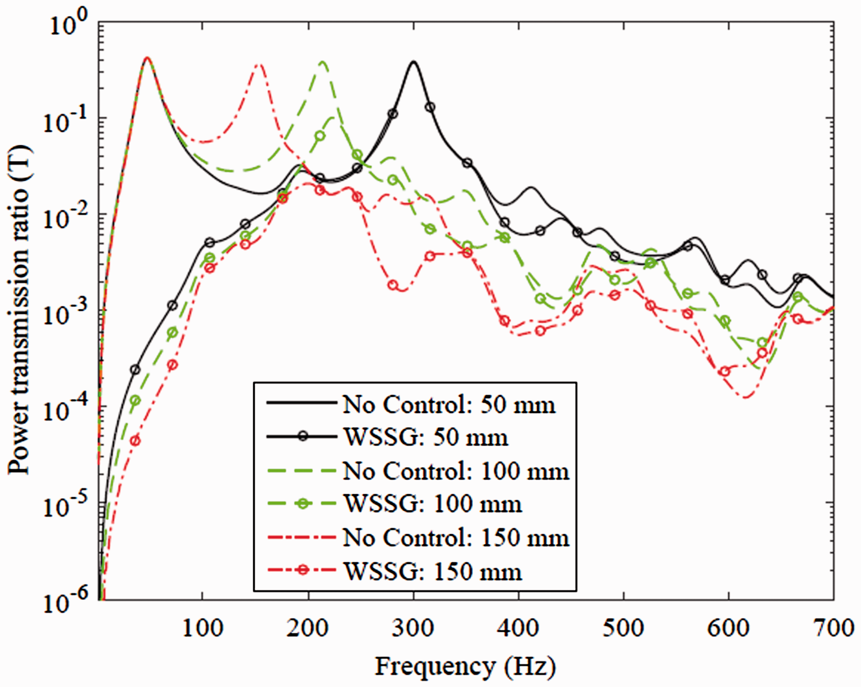
It can be observed from Figure 14 that the first peak before control is unchanged by the variation in thickness of the air cavity which clearly shows that the vibro-acoustic coupling effect on this mode is very negligible. However, the second peak before control has been shifted towards left with increase in the cavity thickness. This is because, this peak is same as the highest peak shown in plot for quadratic sound pressure level (Figure 4), which very much depends upon the vibro-acoustic field inside the cavity, and therefore, increase in air cavity thickness reduces the air stiffness which leads to the reduction of resonance frequency. At
Effects of direction of incident plane wave
Since the azimuthal angle has little effect on sound insulation,
38
therefore, in order to explore the effect of the direction of plane wave on sound power transmission ratio, in this section, the power transmission ratio with frequency has been plotted for three selected values of elevation angle, i.e. Effect of elevation angle on sound power transmission ratio by driving a PZT on panel 1.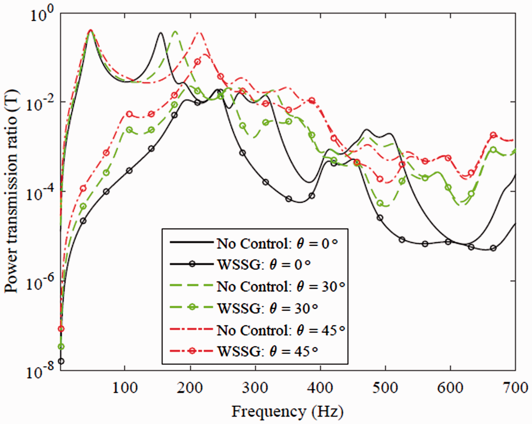
In addition to the above, it can be observed that PZT on panel 1 is able to minimize the WSSG control quantity of panel 2 irrespective of angle of elevation of the incident sound wave and hence, able to attenuate significant amount of radiated sound power. Also, the controlled sound power transmission goes on decreasing as the angle of elevation
Conclusions
For the purpose of controlling sound transmission through double panel partition, minimization of two quantities, volume velocity and weighted sum of special gradients (WSSG), are implemented as two active control methods. Double panel partition with the cavity is modeled using sinusoidal distributed sound velocity potentials, which provides more accurate result as compared to the commonly used cavity modal function method because the rigid baffle bounds the cavity as well as the panel, so that the cavity boundaries restrict the field to sinusoidal distributions parallel to the panel plane. A piezoceramic (PZT) actuator is attached on one side of the panel to minimize the objective function derived from the control methods. Numerical simulations are performed to compare the controlled sound power transmission ratio using the radiation mode analysis, and consequently the effect of thickness and angle of incidence of the primary sound wave are also investigated. Results lead to the following conclusions:
WSSG works better than the volume velocity control strategy to attenuate large amount of transmitted sound power in a double panel partition. The reason is attributed to the ability of WSSG to control the dipole-type of motion of the radiating panel, which can't be detected by volume velocity error sensors, and works exceptionally well at high frequencies because of its power to target multiple acoustic radiation modes unlike the volume velocity, which targets the first acoustic radiation mode only. Air cavity thickness strongly affects the overall vibro-acoustic behavior of the double panel system. With the increase in air cavity thickness, which results in weakening vibro-acoustic coupling, leads to the more reduction in the controlled sound power transmission ratio. Best active control of sound attenuation is achieved when the plane wave is normal to the incident panel surface, and this effect goes on decreasing as the angle of elevation increases.
Footnotes
Declaration of conflicting interests
The author(s) declared no potential conflicts of interest with respect to the research, authorship, and/or publication of this article.
Funding
The author(s) disclosed receipt of the following financial support for the research, authorship, and/or publication of this article: The authors acknowledge the financial support received from the National Graduate Program in Engineering Mechanics (Finland).