
Abstract
An important issue in inertia electromagnetic actuator is that the best performance of device is limited to a very narrow bandwidth around the natural frequency. In order to overcome this issue of the conventional inertia electromagnetic actuator, an inertia electromagnetic actuator capable of adjusting the natural frequency is introduced. This paper presents theoretical investigation, design method, and experimental tests of the natural frequency adjustable electromagnetic actuator. The optimal design scheme is obtained by using ANSOFT software and experimental tests are conducted to examine the practical property of natural frequency adjustable electromagnetic actuator. Following the results obtained by property experiments, a series of active vibration control tests are carried out and experimentally verified that although the measured natural frequencies at different positions cannot satisfy the theoretical values perfectly, natural frequency adjustable electromagnetic actuator still works very well at test frequencies and reduces the vibration from 18.3 dB to 11.3 dB at frequency of 26.25 Hz.
Introduction
Electromagnetic actuators play an important role in vibration control,1,2 where the largest output force of the conventional electromagnetic actuator is restricted to a very narrow bandwidth around the natural frequency. With the purpose of solving this problem, there has been much recent interest in the design of natural frequency adjustable devices whose natural frequency can be adjusted by changing the inertial mass or stiffness.3–6 A wide variety of design solutions have recently been proposed, and a common factor in most of the designs is the introduction of varying stiffness. An approach for controlling the link position and stiffness of a variable stiffness actuator has been proposed by Sardellitti et al., 7 in which the stiffness perceived at the output link is adjusted to match the varying task requirements through a combination of positioning gains and mechanical stiffness. Several adjustable stiffness concepts based on the lever mechanism have been presented and investigated in literature,8,9 compared with the actuator proposed in Jafari et al. 8 this actuator tunes the stiffness by regulating the position of the compliant elements along the lever arm, the design in Jafari et al. 9 changes the position of the lever’s pivot point and is able to adjust the stiffness in a much broader range (from zero to infinity) even by using softer springs and shorter lever arm. The structure proposed by Uemura et al. 10 utilizes a ball screw mechanism to adjust a relationship between infinitesimal displacements of joint rotation and a linear spring. Unlike many other adjustable stiffness structures, available elastic energy of the elastic element is maximum when the stiffness of the proposed structure is maximum. Therefore, the elastic element of this structure can be smaller and more lightweight than the other structures. Active dynamic vibration absorber (ADVA) designed by Ladipo and Muthalif 11 can also provide an adjustable stiffness. The effective spring coil is adaptively changed using an actuator. This gives the opportunity of changing the stiffness property of the ADVA and reducing vibration at all modes of the vibrating building. Variable negative stiffness actuation based on nonlinear deflection characteristics of bucking beams has been proposed by Yalcin et al., 12 which can modulate its stiffness over a uniquely large range that includes zero and negative stiffness values.
This paper presents an alternative approach to adjust the natural frequency and an inertial electromagnetic actuator capable of adjusting the natural frequency is designed and fabricated. The work in this paper is organized as follows. Section “Structure and theoretical analysis of NFAEA” introduces the structure and theoretical analysis of the natural frequency adjustable electromagnetic actuator (NFAEA). Section “Optimal structural design of NFAEA” describes the simulation and optimal analysis of NFAEA by using ANSOFT. This is followed by a series of experimental tests conducted in Section “Experimental investigation” to examine the main properties of NFAEA. The paper concludes in the final section.
Structure and theoretical analysis of NFAEA
The structure of NFAEA depicted in Figure 1 includes two main parts: force-generating part which can generate electromagnetic force when an alternating current passes through coils of NFAEA and regulating part which can adjust the whole stiffness of NFAEA by changing the bottom position of regulating spring. It is worth noting that the regulating part includes four springs, one main spring for supporting the active cell and three regulating springs (tension spring) which are distributed symmetrically and can provide various regulating stiffness.
Structure of natural frequency adjustable electromagnetic actuator. 1: hex screw; 2: upper cover; 3: coil former; 4: coil; 5: upper outer cylinder; 6: yoke; 7: gasket; 8: hex bolt; 9: hex nut; 10: adjustable plate; 11: bottom plate; 12: lower cover; 13: slotted pan head tapping screw; 14: lower cylinder; 15: lower outer cylinder; 16: butterfly nut; 17: adjustable lever; 18: regulating spring; 19: main spring; 20: permanent magnet; 21: main axle; 22: fixed collar; 23: upper cylinder.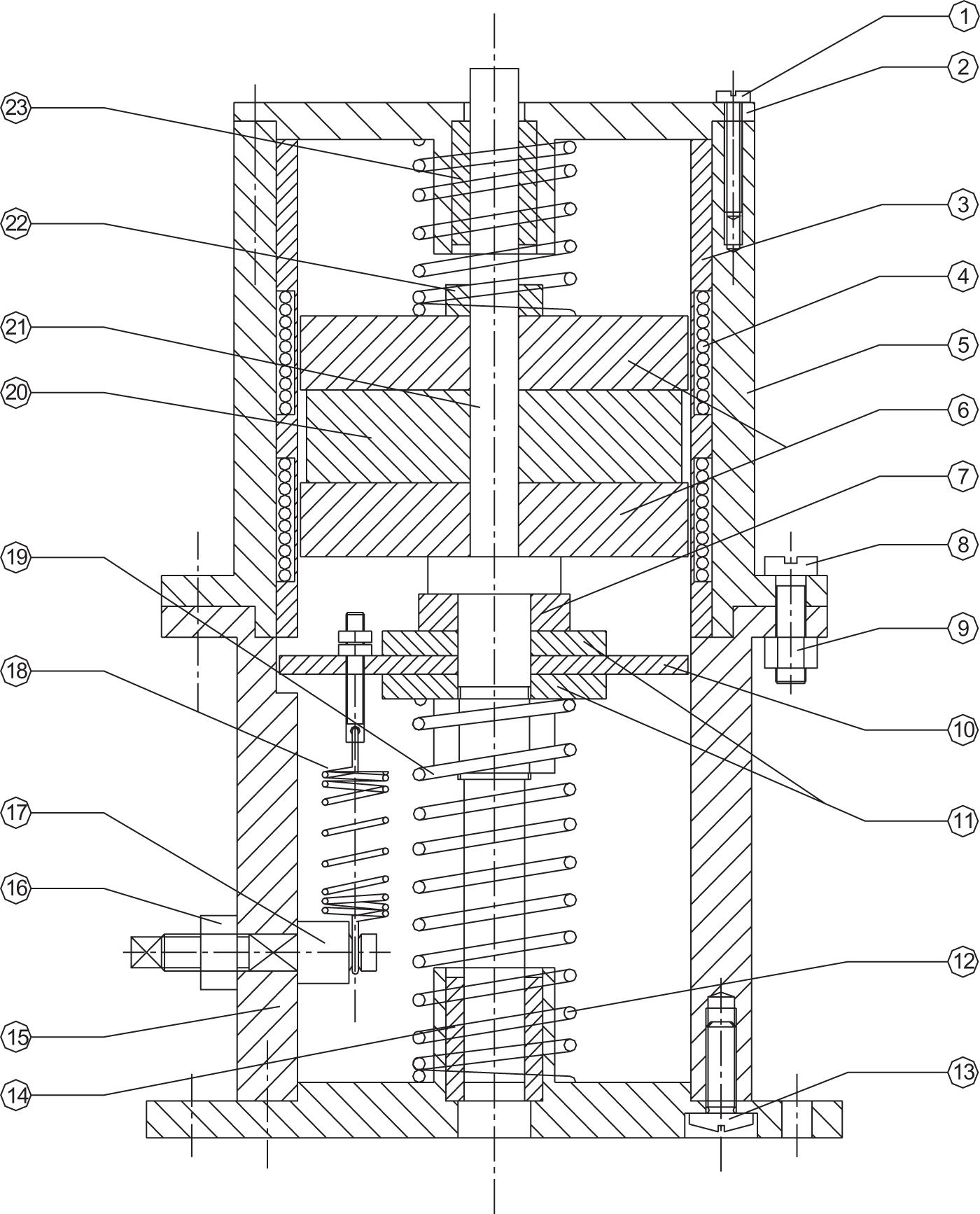
In order to generate a larger force, the conventional approach is to design and fabricate the actuator so that the system’s natural frequency matches the frequency of excitation current. This places an inconvenient constraint on the practical application of the actuator (i.e. consider conventional electromagnetic actuator where the best performance is limited to a very narrow bandwidth around the natural frequency). With a purpose of overcoming this shortcoming of conventional actuator, a stiffness adjustable mechanism shown in Figure 2 is proposed.
Schematic diagram of the stiffness adjustable mechanism.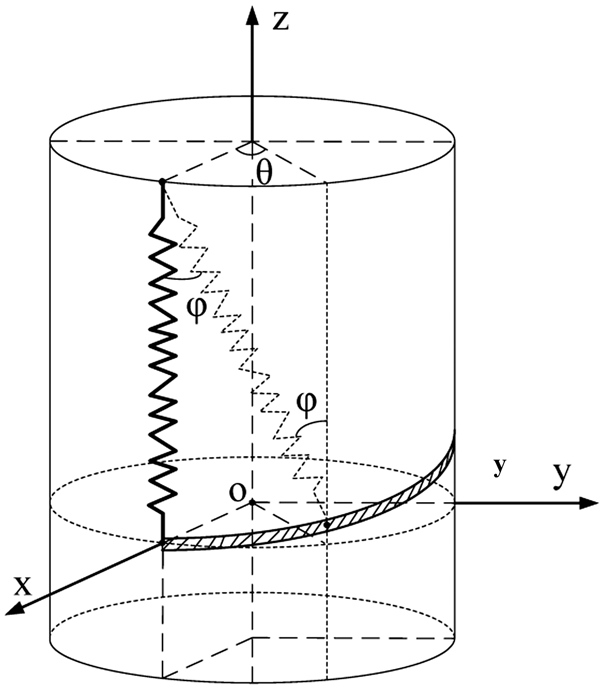
As shown in Figure 2, the top end of the spring is fixed, and the bottom one moves along the groove on the outer cylinder. As the length of the adjusting spring defined as l is kept invariable, the trajectory of the bottom end of the adjusting spring satisfies the equations below.

The equivalent vertical stiffness of the regulating spring varies with the angle, ϕ (as shown in Figure 2).


Thus, equation (2) can be rewritten as a function of displacement, z.

However, a smooth trajectory of the groove is almost useless in a practical system (because the bottom end of regulating spring cannot be fixed in this situation), so five special regulating positions are selected to adjust the stiffness of the system. At these five positions (shown in Figure 3), represented by 4, 3, 2, 1, and 0, the equivalent vertical stiffness satisfies Five positions of NFAEA. NFAEA: natural frequency adjustable electromagnetic actuator.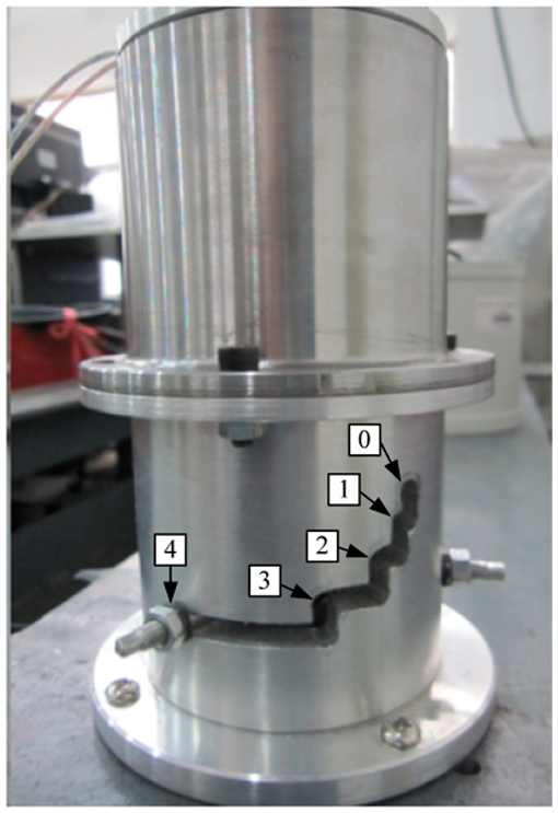
Optimal structural design of NFAEA
This section describes the simulation of magnetic circuit and optimal analysis of some fundamental components of NFAEA. Simulation model of actual size is built in ANSOFT software and the size of every component varies while holding that of other components constant. Referring to results generated by the magnetic field simulation of NFAEA, the optimal mechanical designing size of NFAEA is obtained.
Distributions of magnetic field and magnetic induction intensity of the actuator
Distributions of magnetic field and magnetic induction intensity of the actuator in the case that the NFAEA is not powered are shown in Figures 4 and 5.
Distribution of magnetic field. Distribution of magnetic induction intensity.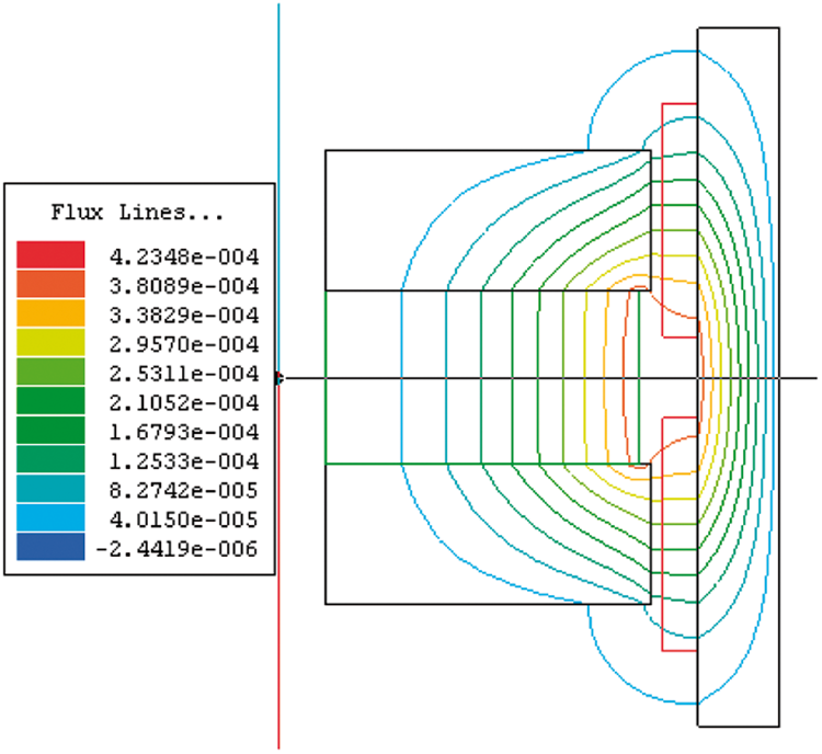
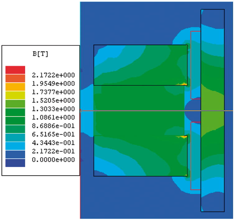
It is shown in Figure 4 that almost all magnetic lines distribute along the closed magnetic circuit composed of upper and lower yoke, air gap, coil, and the outer magnetic cylinder. As there is no magnetic dispersion in the magnetic field of NFAEA, it is considered that the magnetic field design of NFAEA is reasonable. 13
Figure 5 shows the distribution of magnetic induction intensity corresponding to Figure 4. Although the joint of yoke and permanent magnet are slightly saturated, the whole model has a very good magnetic energy utilization rate. In general, the design of magnetic circuit is feasible.
Optimal analysis of the thickness of yoke
The performance of NFAEA depends mostly on the output electromagnetic force and the magnetic induced intensity of coil. In an effort to optimize the thickness of yoke, NFAEA is electrified by a current of 1 A and the thickness of yoke varies from 1 mm to 15 mm (referring to the design experience of actuator in Liu et al. 14 ) while holding all other experimental variables constant.
It can be seen in Figure 6 that electromagnetic force and magnetic induced intensity increase before 11 mm, then remain stable between 11 mm and 13 mm, and decrease after 13 mm. That is because when the thickness of yoke is small, magnetic saturation trend exists in the magnetic field (shown as red areas in Figure 5) and decreases with the increase of thickness of yoke. When the thickness is 12 mm, the saturation phenomenon disappears and the magnetic field achieves the highest energy utilization rate. As the saturation phenomenon disappears after 11 mm, the electromagnetic force and magnetic induced intensity will remain almost invariable, shown as trend between 11 mm and 13 mm. However, the electromagnetic force becomes small when the thickness of yoke is larger than 13 mm that is because the height of coils in simulation model is 20 mm and some leakage flux will round above the coils if the thickness of yoke is too large. For the purpose of better avoiding magnetic saturation, 12 mm is chosen as the thickness of yoke.
Impact of the thickness of yoke on electromagnetic force and magnetic induced intensity. (a) Fa vs. the thickness of yoke and (b) Bg vs. the thickness of yoke.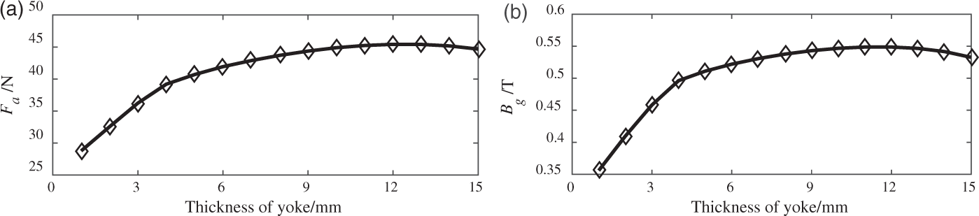
Optimal analysis of the thickness of magnetic conductive outer cylinder
The optimal design of magnetic conductive outer cylinder is almost the same as that of yoke introduced before, but the thickness of cylinder varies from 1 mm to 15 mm. The relation curves of electromagnetic force as function of thickness and magnetic induced intensity as function of thickness are shown in Figure 7(a) and (b), respectively.
Impact of the thickness of magnetic conductive outer cylinder on electromagnetic force and magnetic induced intensity. (a) Fa vs. the thickness of outer cylinder and (b) Bg vs. the thickness of outer cylinder.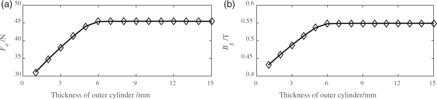
Based on the comparison of Figure 7(a) and (b), it can be found that thickness over 6 mm can be selected as the optimal thickness of magnetic conductive outer cylinder where the system outputs the largest electromagnetic force and the magnetic field achieves the highest energy utilization rate. Considering the factors such as processing installation, 7 mm is chosen as the thickness of magnetic conduction outer cylinder.
Optimal analysis of the radius of yoke
Radius of yoke also has a powerful influence on the electromagnetic force and magnetic induced intensity, as shown in Figure 8. In this simulation test, the radius of yoke varies from 31 mm to 41 mm.
Impact of the radius of yoke on electromagnetic force and magnetic induced intensity. (a) Fa vs. the radius of yoke and (b) Bg vs. the radius of yoke.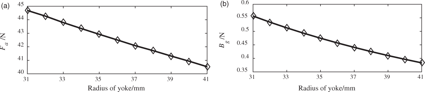
It can be seen in Figure 8 that both electromagnetic force and magnetic induced intensity decrease with the incremental radius of yoke. That is because the larger the radius of yoke is the greater the magnetic flux leakage will be. Even though the length of coil in the magnetic field becomes larger, the magnetic induced intensity decreases faster and the magnitude of electromagnetic force still decreases as
15

Design of NFAEA prototype
The mechanical designing size of the NFAEA.
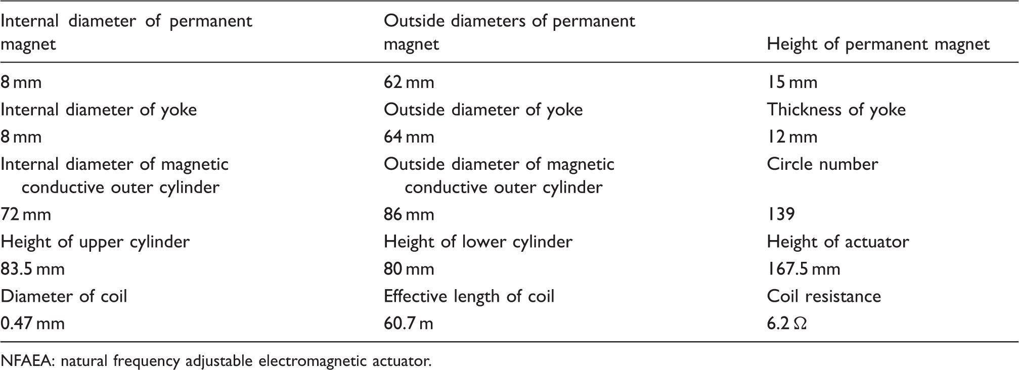
NFAEA: natural frequency adjustable electromagnetic actuator.
Experimental investigation
This section describes the series of experiments that were performed to test the NFAEA’s properties. The experimental tests can be broadly separated into the performance of: (1) position changes while holding all other experimental variables constant, (2) the excitation current varies while holding all other experimental variables constant, and (3) the effect of control when NFAEA is used in active vibration control experimental tests. As the first two almost use the same equipment, these are placed together to study.
Property experimental tests of NFAEA
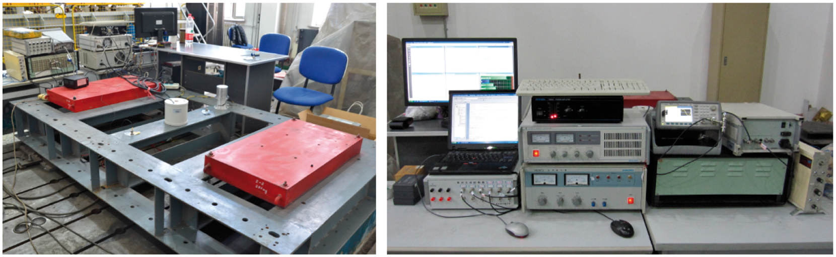
Figure 9 shows the schematic diagram of property experimental tests and Figure 10 shows the primary equipment used during the property experimental tests. Signal generated by B&K3560B is transmitted to NFAEA in the form of current via power amplifier. The acceleration signal detected by acceleration sensor which is attached to the main axle via screw arbor is transmitted to B&K3560B in the form of voltage signal via impedance converter. Finally, the signal will be processed by using a computer connected with B&K3560. In an effort to detect the change of current, a multimeter is connected between the power amplifier and NFAEA. In these tests, the signal provided by B&K3560B is white noise, which is a random signal with a constant power spectral density. The amplitude–frequency characteristic of NFAEA changes against the different bottom position of regulating spring while holding all other experimental variables constant. It should be noticed that the pole above the sensor in Figures 9 and 10 was removed in acceleration measurements to release the acceleration sensor.
Schematic diagram of property experimental tests. Primary equipment used during property experiments.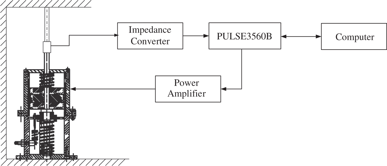
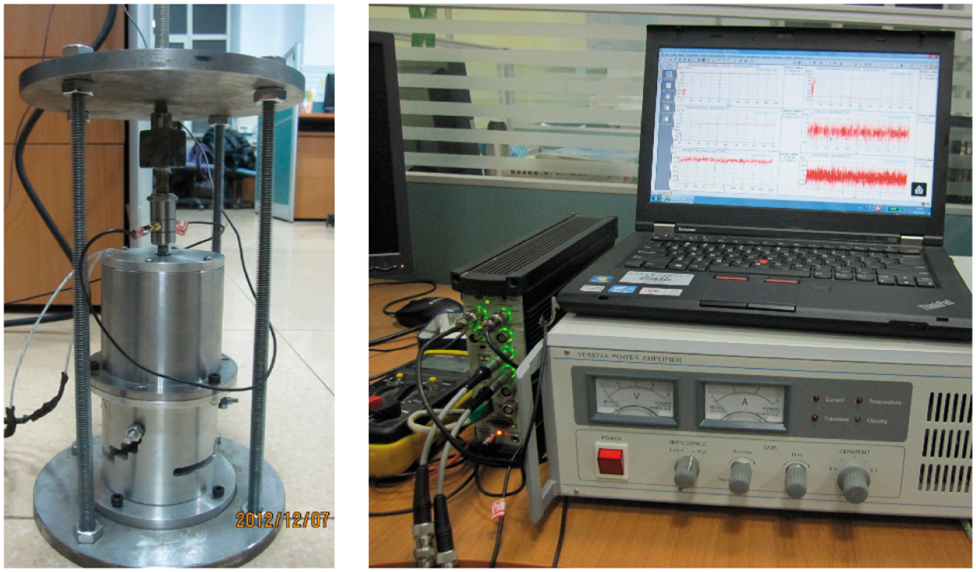
Figure 11 shows the acceleration response curves for different positions, from which the natural frequency can be obtained. Natural frequencies of different situations obtained from measured experiments are listed in Table 2.
Acceleration response curves for different positions. (a) k′ = k, Position 4, (b) k′ = 3k/4, Position 3, (c) k′ = k/2, Position 2, (d) k′ = k/4, Position 1 and (e) k′ = 0, Position 0. Natural frequency of different positions measured experimentally.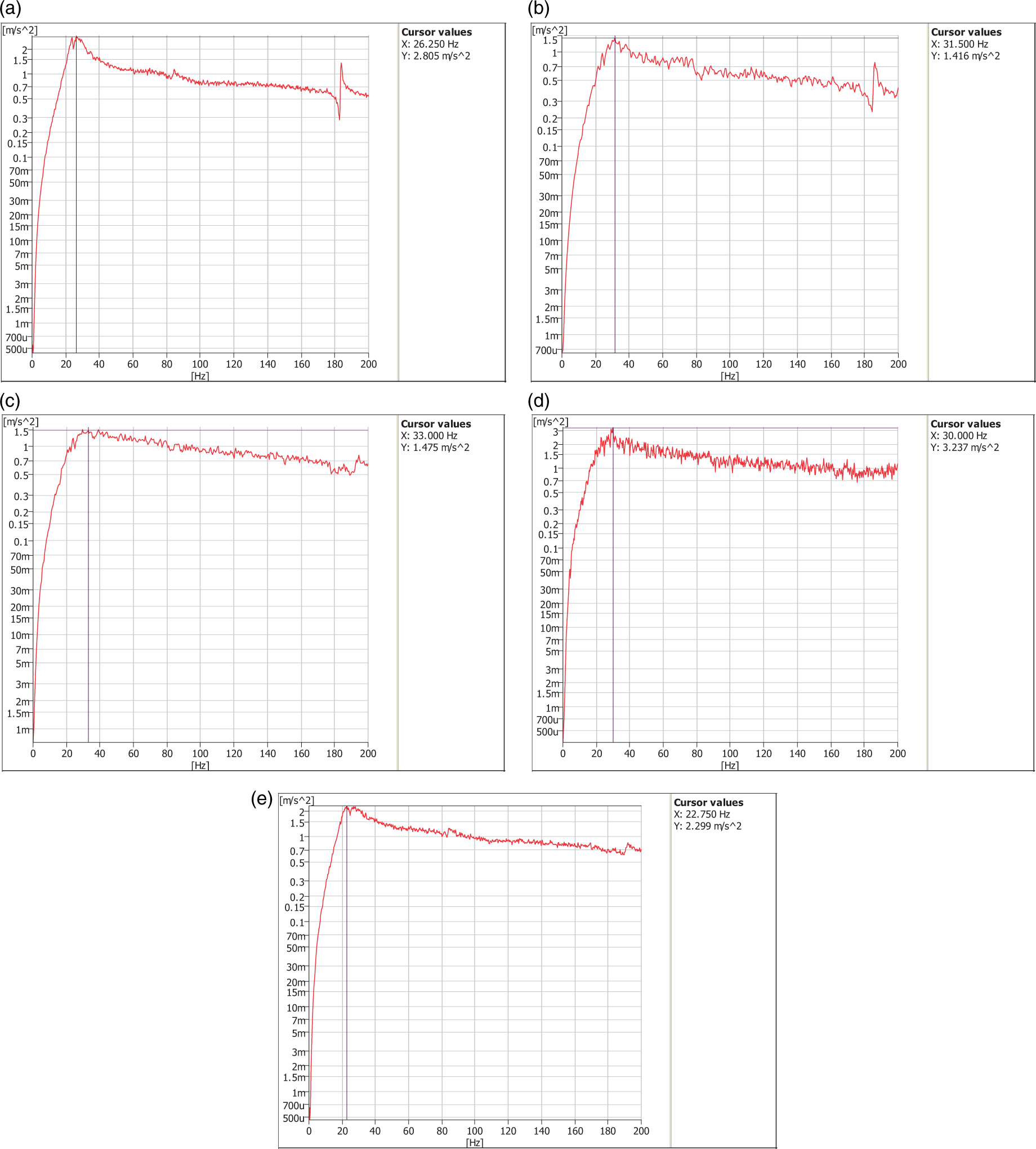
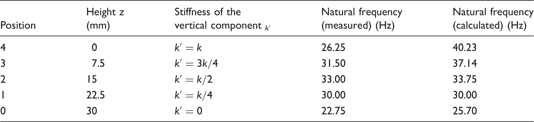
To appraise the property of NFAEA fully, it is necessary to make a comparison of measured experimental results with calculated theoretical results. It can be seen in Table 2 that the trend (from position 3 to 4) of calculated natural frequencies is quite different from that of experimentally measured frequencies. This is because the regulating spring used in this design is tension spring which is designed to stretch for 7 mm rather than the artifactitious stretch elongation of 3 mm. This results in when the active cell moves down 3 mm, the regulating spring recovers its original length and is useless to adjust the stiffness in the continuous downward motion. The more oblique the regulating spring is, the smaller the error is. At other three positions (0, 1, and 2), the influence caused by artifactitious error can be neglected, and the experimental measured natural frequency compares well with the theoretically calculated natural frequency. The reason no accurate regulating spring is fabricated is that the purpose of this work is to present a new approach for adjusting stiffness and verify its feasibility rather than put it into practical application at this time.
Figure 12 shows the acceleration as function of frequency trajectory of NFAEA under various currents. Position 0 is selected as the experimental position. For the purpose of investigating the relationship between inertia force and excitation current, various magnitude currents with the same frequency (100 Hz) is applied to NFAEA.
Acceleration of active cell as a function of the excitation current. (a) Current, 0.3A, (b) Current, 0.4A, (c) Current, 0.5A, (d) Current, 0.6A, (e) Current, 0.7A and (f) Current, 0.8A.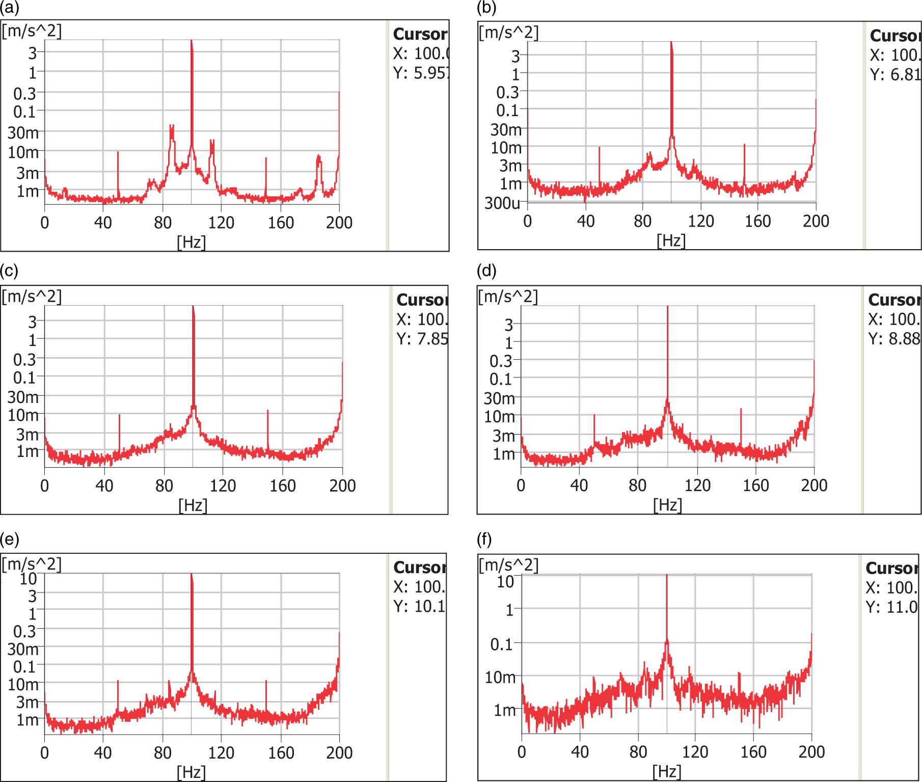
Based on the data from Figure 12, the inertia force as function of current is shown in Figure 13. As shown in Figure 13, the magnitude of inertia force is proportional to that of excitation current. This linear characteristic matches favorably with theoretical predictions as mentioned before.
Inertial force as a function of the excitation current.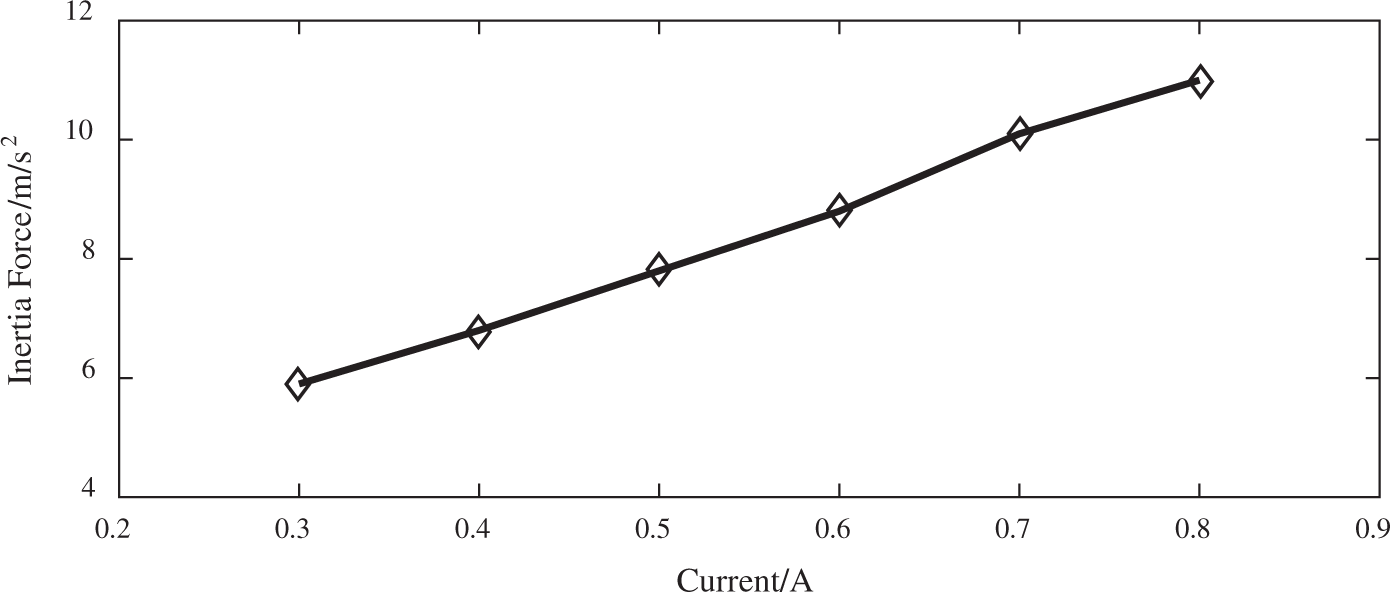
Active vibration control experimental tests of NFAEA
From the experiment above, it is found that the natural frequency peaks of NFAEA at position 0 and 4 (especially position 4, shown as Figure 11) are more obvious than others, so these are chosen as the experimental positions. Figure 14 shows the experimental program based on x-LMS algorithm and Figure 15 shows the primary equipment used during the experimental tests.
Schematic diagram of active vibration control experimental tests. Primary equipment used during experimental tests.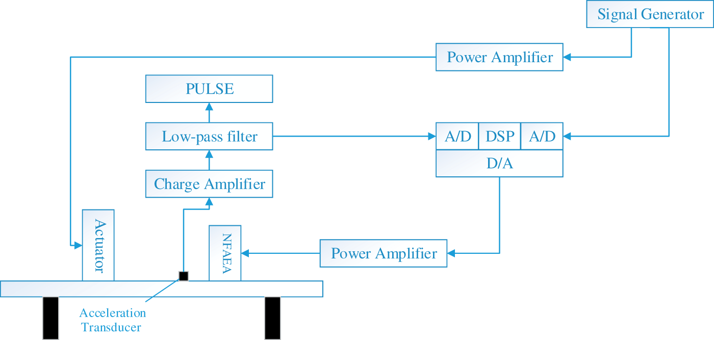
Single frequency sinusoidal signal (22.75 Hz and 26.25 Hz) was applied to the experimental system and the effectiveness of active control could be realized using the x-LMS algorithm. The effectiveness of active vibration control of 0 and 4 was measured, and this is shown in Figures 16 to 19.
Comparison of the effect of position 0 before and after controlling at frequency 22.75 Hz. (a) Comparison in time domain and (b) Comparison in frequency domain.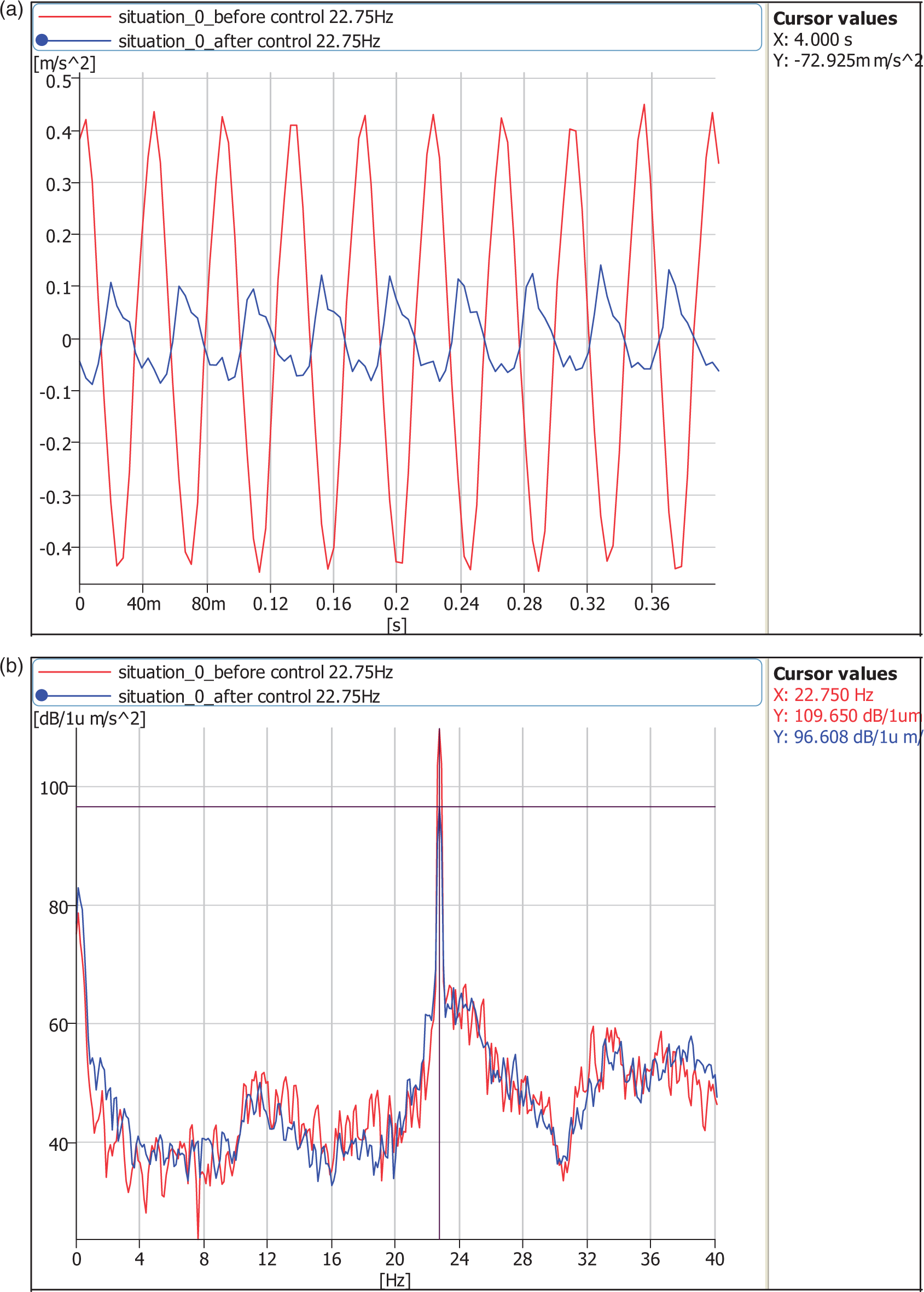
As shown in Figures 16 and 17, when the trestle was excited at the frequency of 22.75 Hz, the magnitude of the vibration at position 0 decreased 13.0 dB, however, only 12.6 dB at position 4. It is worth noting that the natural frequency of NFAEA is 22.75 Hz at position 0 and 30.00 Hz at position 4, as given in Table 2. To determine whether NFAEA has a better performance of active vibration control if it works at natural frequency, active vibration control experimental tests at other frequencies were conducted.
Comparison of the effect of position 4 before and after controlling at frequency 22.75 Hz. (a) Comparison in time domain and (b) Comparison in frequency domain.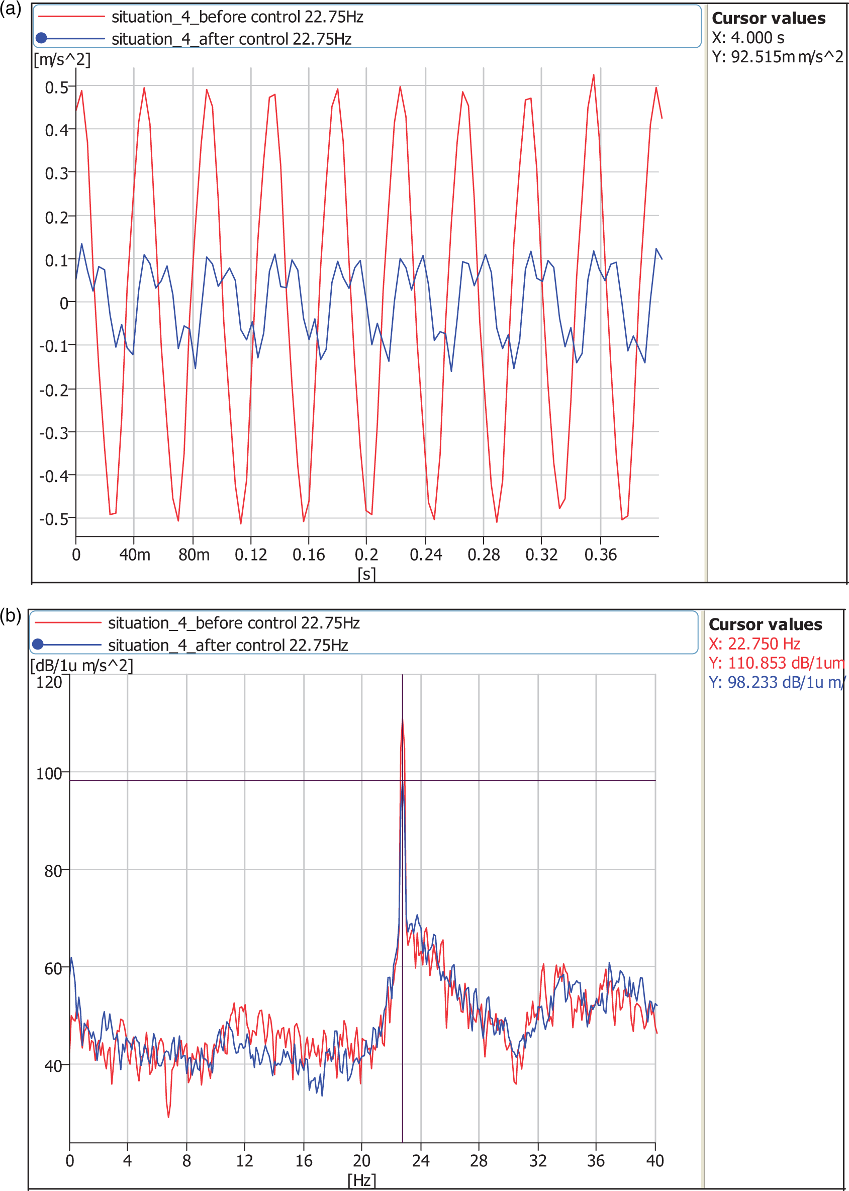
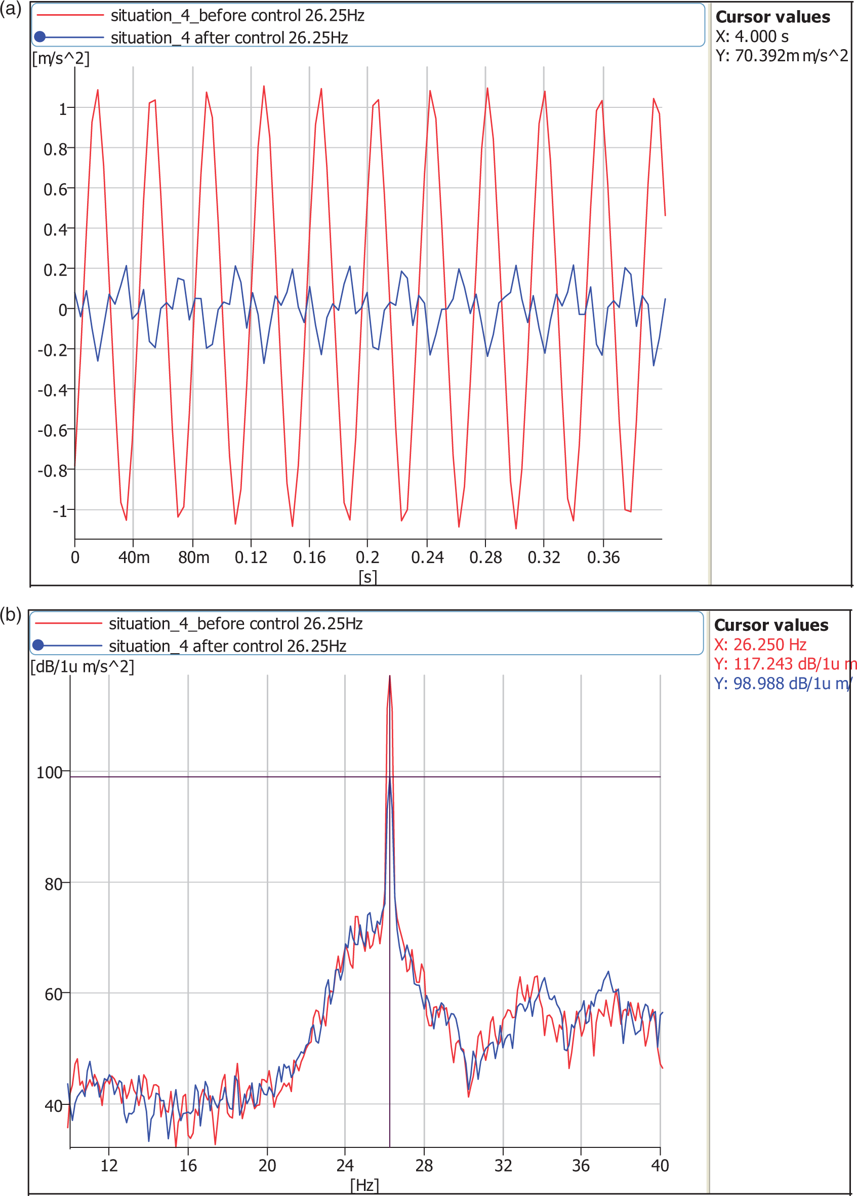
The frequency of 26.25 Hz was selected as the test frequency, which is also the natural frequency of NFAEA at position 4. It can be seen in Figures 18 and 19 that the performance of NFAEA at position 4 was much better than that of NFAEA at position 0.
Comparison of the effect of position 0 before and after controlling at frequency 26.25 Hz. (a) Comparison in time domain and (b) Comparison in frequency domain. Comparison of the effect of position 4 before and after controlling at frequency 26.25 Hz. (a) Comparison in time domain and (b) Comparison in frequency domain.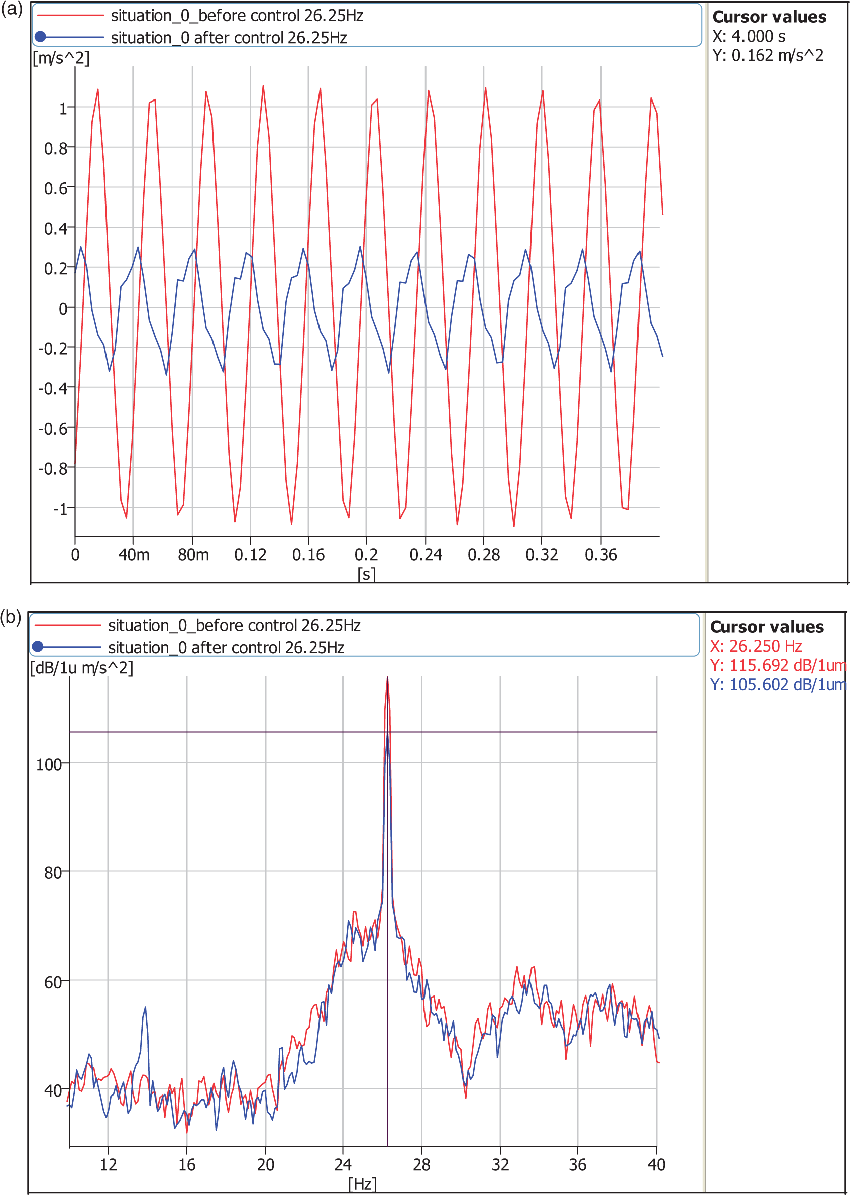
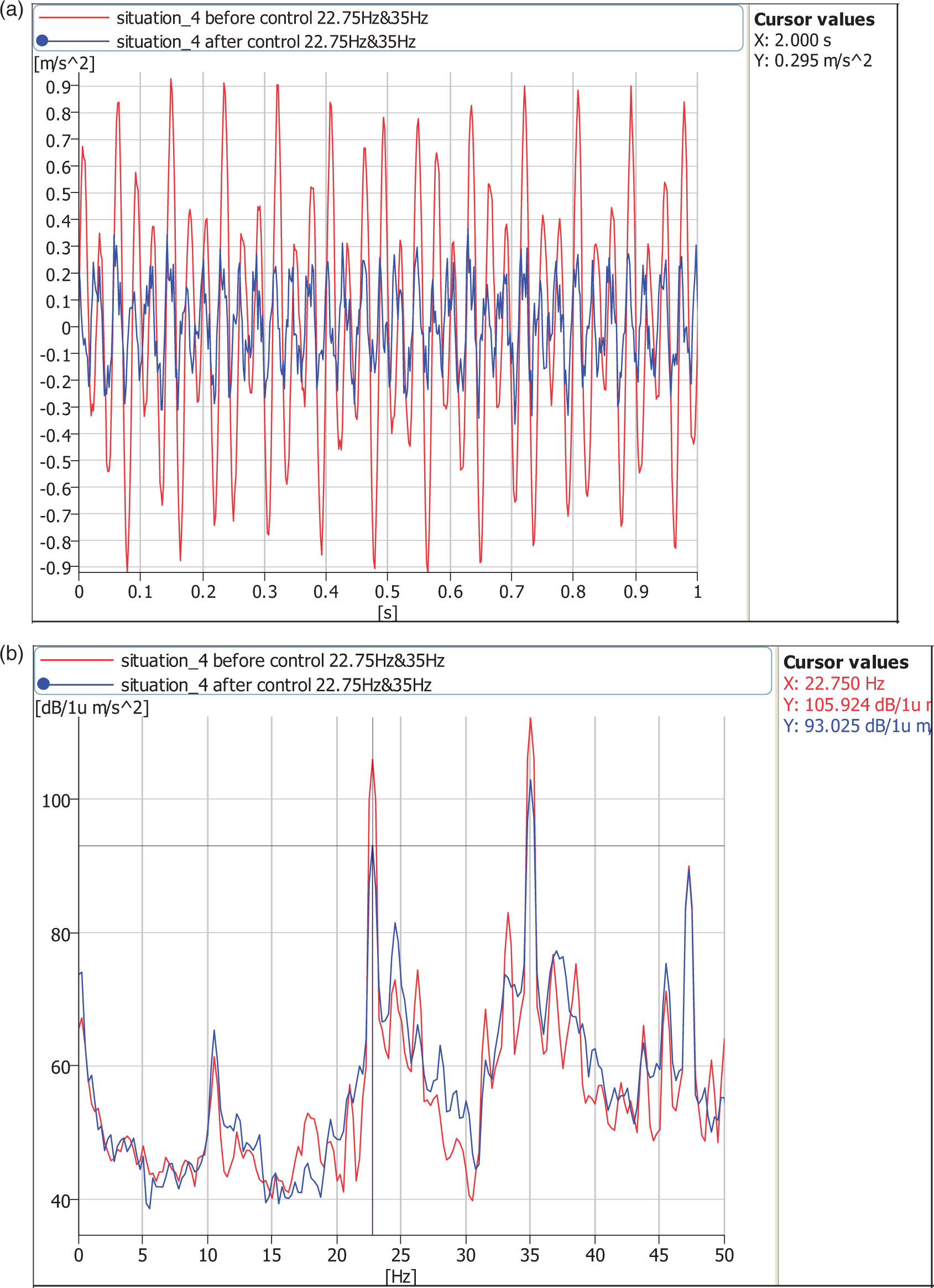
Besides, dual frequency control experiments of 22.75 Hz & 35 Hz and 26.25 Hz & 35 Hz (shown in Figures 20 to 23) were also conducted and the results of these experimental tests are summarized in Table 3.
Comparison of the effect of position 0 before and after controlling at frequency 22.75 Hz and frequency 35 Hz. (a) Comparison in time domain and (b) Comparison in frequency domain. Comparison of the effect of position 4 before and after controlling at frequency 22.75 Hz and frequency 35 Hz. (a) Comparison in time domain and (b) Comparison in frequency domain. Comparison of the effect of position 0 before and after controlling at frequency 26.25 Hz and frequency 35 Hz. (a) Comparison in time domain and (b) Comparison in frequency domain. Comparison of the effect of position 4 before and after controlling at frequency 26.25 Hz and frequency 35 Hz. (a) Comparison in time domain and (b) Comparison in frequency domain. Controlling effect at different positions.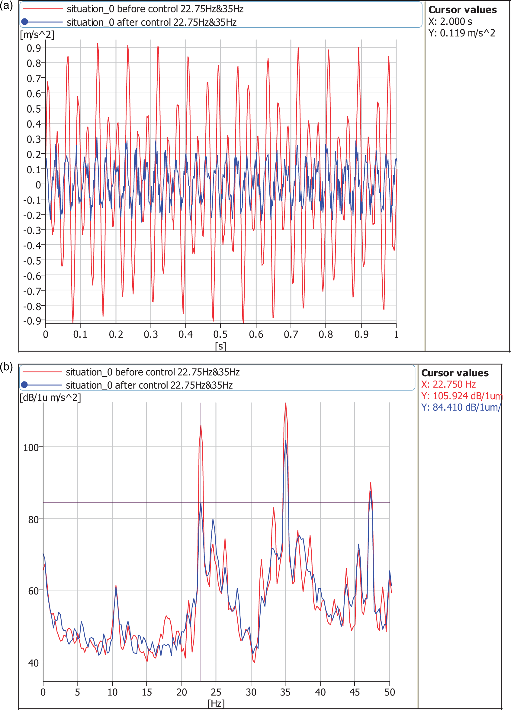
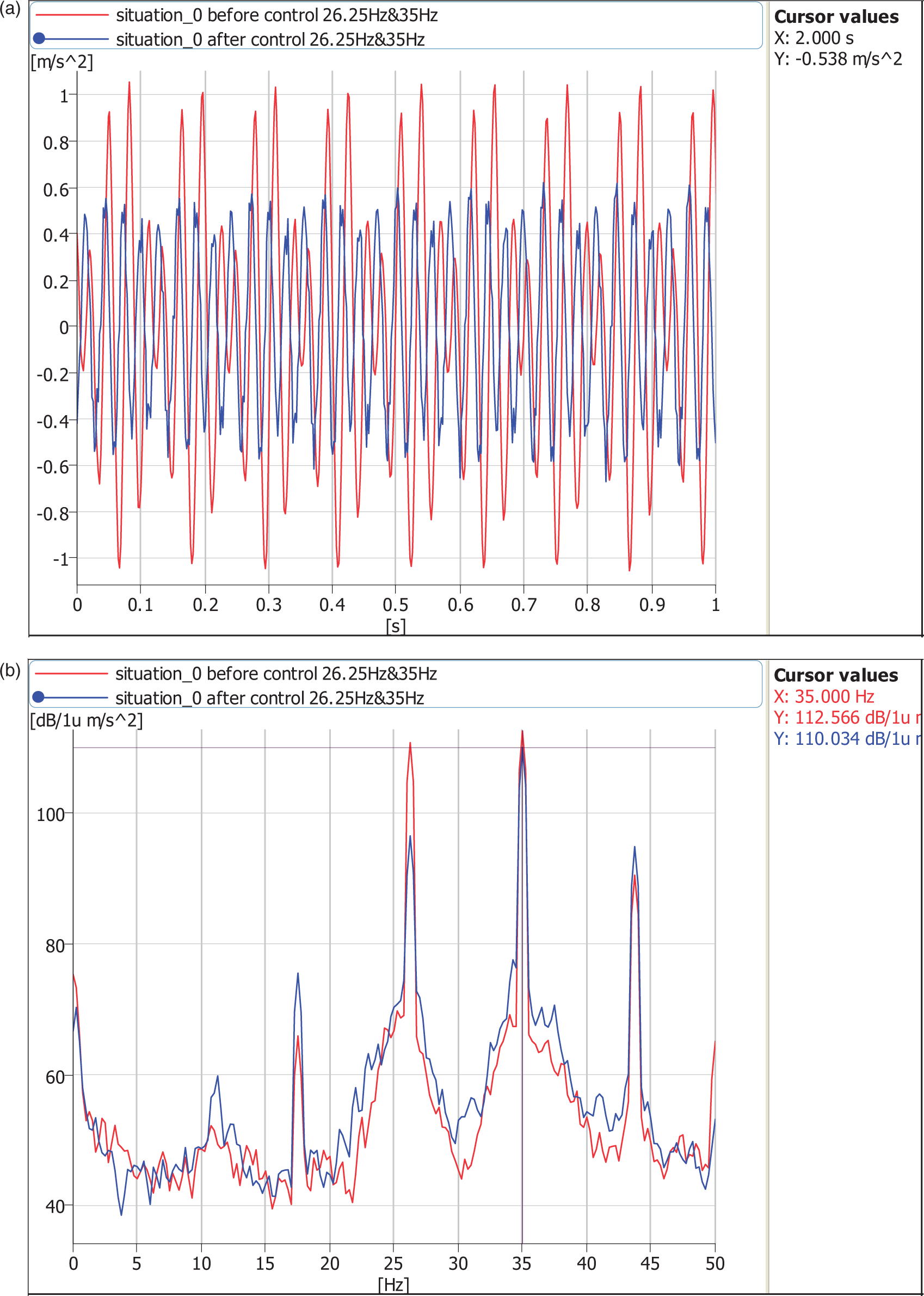
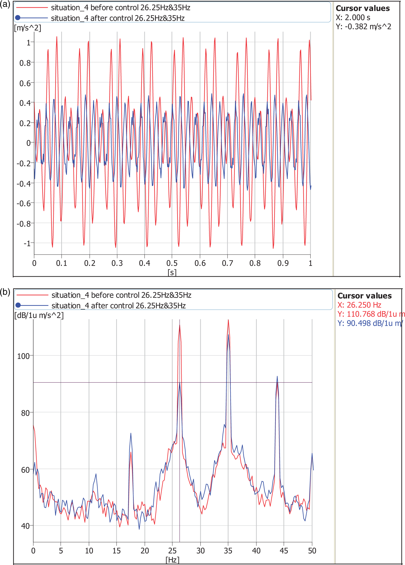
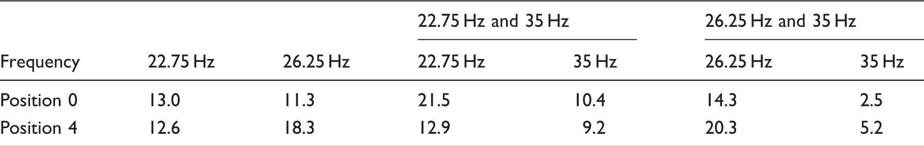
The natural frequency of NFAEA is 22.75 at position 0, and 26.25 at position 4, as given in Table 2. It can be concluded from Table 3 that NFAEA of each position will have its best performance if it works at its corresponding natural frequency. Compared with frequency of 35 Hz, frequency of 22.75 Hz has always led to better performance at both positions 0 and 4. That is because the 22.75 Hz frequency is much closer to natural frequencies of these two positions. As 22.75 Hz is the natural frequency of position 0, so the performance at 0 was better than that of position 4. The closer to natural frequency the excitation frequency is, the better control performance the NFAEA will have. The same analysis method is also applied to 26.25 Hz & 35 Hz, and this verifies the conclusions made above.
Conclusion
In this paper, a NFAEA has been designed and theoretical and experimental investigations have been presented. A novel stiffness adjustable mechanism has been introduced, which can adjust the whole stiffness of NFAEA by changing the bottom position of regulating spring. Referring to the results obtained by simulations in ANSOFT software, the prototype of NFAEA has been designed and fabricated. Following the results obtained by property experiments, a series of active vibration control tests have been carried out and experimentally verified that although the measured natural frequencies at different positions cannot satisfy the theoretical values perfectly, NFAEA still works very well at the test value. Furthermore, if the primary excitation frequency includes any natural frequency of NFAEA at these five positions, the performance of NFAEA will be much better than the other situations. In conclusion, the NFAEA has a better performance than traditional actuators or has better capability of adjusting the natural frequency. The design of NFAEA is feasible.
Footnotes
Declaration of conflicting interests
The author(s) declared no potential conflicts of interest with respect to the research, authorship, and/or publication of this article.
Funding
The author(s) received no financial support for the research, authorship, and/or publication of this article.