
Abstract
The development and implementation of a traffic noise propagation calculation method based on beam tracing subordinated to spatial subdivision is presented to simulate noise attenuation in three-dimensional space. In the method, complex scenes constituted by road, different buildings and thin sound barrier and all noise propagation modes including direct, reflected, diffracted and composite are considered. The paper analyses the accuracy and efficiency of the method from the perspectives of subdivision precise of obstacles and road, beam thresholds and re-subdivision of sound barrier areas. The results presented by tendencies chart and formulas indicate that a meticulous subdivision and threshold settings lead to more accurate but less efficient method. Results of experiment and case study show the error to be no more than 0.3 dB when the building subdivision precisions (0.5 m), road subdivision precision (2 m) and thresholds (a length threshold of 500 m, three reflections and one diffraction) are set appropriately. Re-subdivision of sound barriers is presented to handle the trade-off between accuracy and efficiency caused by discrepancies in the geometric dimensions. In the case study, re-subdivision mitigates the trade-off between accuracy and efficiency, with almost the same accuracy by spending only approximately 1/10 of the time. A building subdivision precision of 1 m, a road subdivision precision of 2 m, a 500 m beam length, 3–5 reflections and a single diffraction are recommended for the method.
Keywords
Introduction
In recent years, road traffic noise pollution has become a significant issue in urban areas, drawing the attention of both society and scholars. Statistics from the European Union, 1 Hong Kong 2 and Iran 3 and relevant studies4,5 show that traffic noise pollution is increasing and severely affecting people’s lives. Complicated roads, buildings and sound barriers make road traffic noise propagation simulation more challenging. Hence, it is essential to calculate the attenuation of road traffic noise caused by buildings, sound barriers and other obstacles.
With the development of computer technology, mathematical simulations based on geometric acoustic methods, which include the ray tracing method (RTM),6,7 beam tracing method (BTM),8,9 image source method (ISM)10,11 and comprehensive methods, 12 have been widely and practically applied in traffic noise simulation. BTM, as an extension of RTM, not only overcomes the weakness of only reflection calculation of ISM but also addresses the sampling errors that affect RTM 13 due to its spatial continuity. However, when obstacles are abundant, BTM becomes computationally intensive because it simulates the complex diffusion process of sound waves.14,15 Therefore, the greatest challenge is to accelerate the recursive geometric calculation under complicated conditions while utilising the BTM to calculate the noise propagation among buildings and other obstacles. There are many papers discussing the accuracy or efficiency of BTM. As such, Yousefzadeh and Hodgson, 16 Sikora et al., 17 Jeong and lh 18 and some other authors applied BTM in room acoustics and presented the relationship between method accuracy (efficiency) and frequency, sound strength, reverberation time, aspect ratios and absorptions, etc. While, aim at traffic noise simulation in the urban area, scholars have completed a series of studies on improving the accuracy and efficiency of noise propagation simulations. Lewers 19 used the central line of beams as a tracing target, which improves the accuracy and efficiency when there are frequent reflections, but when there is less reflection, accuracy decreases, as paths may be lost. De Coensel et al. 20 proposed that the computational area be subdivided into subspaces and that a combination of BTM and ISM be adopted to elucidate sound propagation through barriers. Other scholars21,22 employed binary space partitioning to pre-treat the space into convex polygons and then applied the BTM in the ordered convex polygon environment. The two approaches mentioned above improve the calculation efficiency of noise propagation among building groups to some degree but fail to account for complex reflections and diffractions in the 3D space. Existing studies mostly represent special situations of traffic noise. Karimi and Younesian 23 and Mohammad and Fard 24 took sound barriers as study object. Thorsson et al. 25 developed models for traffic noise attenuation in building blocks based on experience. Ismail and Oldham 26 presented a simple model for the calculation of noise reflection and diffraction among buildings using a scale model. Luo et al. 27 developed a dynamic model for noise propagation simulation with significantly increased efficiency and dynamism, but it ignores the calculations in 3D space. These studies simplified the beams and subdivided spaces within a group of buildings to boost the efficiency but failed to meet the requirements of accuracy and efficiency in addressing multiple reflections and diffractions, especially in 3D space. Furthermore, when the sound barriers are significantly different from the buildings in size, the existing studies do not consider them in their calculations. Those methods also neglect the accuracy and efficiency in a 3D scene from the perspective of obstacle and road subdivision precision.
In simulating the multiple reflections and diffractions in a 3D scene, the major challenge is to balance the accuracy and efficiency of calculation. In a complicated situation comprising diverse elements, this is of great importance. The thresholds of beam length and the numbers of reflections and diffractions ultimately determine the error scale as well as the efficiency of the calculation. In a real environment, the discrepancies in the sizes of obstacles in 3D, the complexity of the obstacles and the road layout, and the existence of sound barriers and roads make precisely addressing the obstacle subdivision and road traffic noise emission difficult. Thus, it is necessary to analyse the subdivision precision of obstacles and roads and the re-subdivision of areas around sound barriers. Spatial subdivision is an important method to evaluate a complex space structure and offer topological modelling. 28 A traffic noise propagation calculation method based on beam tracing subordinated to spatial subdivision is presented to simulate noise attenuation in 3D space. Experiments and case studies are used to analyse the variation of the accuracy and efficiency caused by the precision of the subdivision of obstacles and roads, the re-subdivision of the barrier areas and three beam tracing thresholds (length, reflection time and diffraction times).
The paper persuades three new objectives. First, a traffic noise propagation calculation method based on BTM subordinated to spatial subdivision is presented to simulate noise attenuation in 3D space. And the method subdivides a whole space into tetrahedral networks with the goal of transforming the global search of beam tracing into a local one which can largely increase the calculation efficiency in 3D. Second, it is an original work that re-subdivision of sound barriers is presented to handle the trade-off between accuracy and efficiency caused by the discrepancies in the geometric dimensions. Third, analysis of accuracy and efficiency of BTM from the perspective of subdivision precision, road discretisation and re-subdivision of sound barrier is also a development of the studies in road traffic noise propagation simulation.
Principles and method
The method is based on the basic assumption that the sound waves are non-flexural, which propagate in line in urban area. And refractions and interferences are ignored. The method primarily subdivides a whole space into tetrahedral networks, with the goal of transforming the global search of beam tracing into a local one. Upon recursively obtaining the paths of the sound beams, road traffic noise emission and propagation models are applied to calculate the sound press level (SPL) of the receivers. With the goal of solving the problems caused by discrepancies in the sizes of buildings and sound barriers, the method presents an effective approach to re-subdividing a local area.
Road traffic noise propagation calculation method
The calculation of the propagation of road traffic noise is divided into three phases in this method, as presented in Figure 1: 3D spatial subdivision, beam tracing and path generation. Spatial subdivision divides whole space into a constrained Delaunay tetrahedral network
29
to accelerate the construction of the tree structures of the acoustic beams by transforming the global search process of beam tracing into a local one. The method can be described as follows: (a) The whole space containing the obstacles and roads is subdivided into a constrained Delaunay tetrahedral network, and all the data of the network are stored in the database. (b) After the position and direction information of the sources and the tetrahedral network are stored in the memory, the beam tree is recursively generated. The trees start at the source and store messages from the areas that the acoustic beams reach during the process of sound propagation, reflection and diffraction. (c) Corresponding beam tree structures are established for all the sources, according to step (b). (d) Finally, the tetrahedron containing the receiver is identified, and all the nodes in the tree structure until the end of trace are enumerated, and the nodes that meet the prerequisites of beam tracking and generate one or more paths of noise propagation are marked.
Procedure of noise propagation.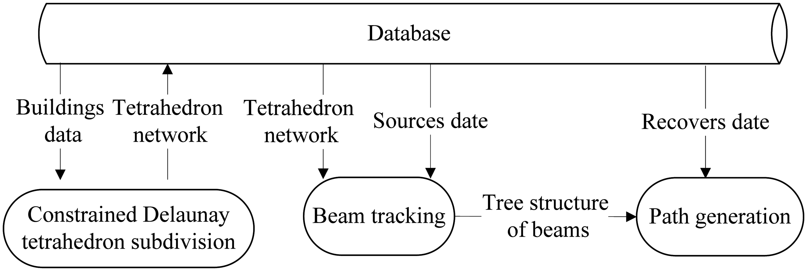
For each receiver, with its acquired paths and models of road traffic noise emission and propagation, the attenuation can be calculated within a complex 3D scene.
Spatial subdivision
This method subdivides the whole space into tetrahedral networks with the goal of transforming the global search of beam tracing into a local one. Incremental insertion was adopted in this method to obtain a constrained Delaunay tetrahedron network, with the process including the following steps: (a) Insert boundary control points in the space to form a convex hull, a closed surface that includes all sources of sound and obstacles. (b) All inserted nodes are based on Delaunay triangulation. To obtain qualified tetrahedrons, select the only qualified method of triangulation for the subdivision for each node. (c) Repeat step (b) for all nodes in the affected areas to obtain the local optimal tetrahedral network. (d) Revive the boundaries of all obstacles in their respective influential tetrahedrons to determine the properties of the barriers in the beam tracing process.
In reality, the sizes of buildings and roads are usually between several meters and tens of meters or larger, but thin-walled barriers like sound barriers are merely several centimetres thick. Hence, there is a stark difference between the degrees of precision used for the subdivisions of buildings and sound barriers. When the precision is low, it conventionally appears as thin tetrahedrons around small obstacles such as sound barriers. If a thin tetrahedron appears with four nodes almost sharing one facade, errors will occur through beam divergence, and path repetition may occur in the process of beam tracing and path generation, causing the calculation to be either inaccurate or incomputable. As the precision increases, the workload grows exponentially, which seriously decreases the efficiency. Re-subdivision (see Figure 2) is designed to solve the above problem. First, the space is subdivided into tetrahedrons, ignoring small obstacles, and tree structures are generated. Then, the barrier-influenced areas are re-subdivided, and elaborate tetrahedrons are constructed. Accordingly, new tree structures are obtained after the data modification, and the noise propagation simulation in the re-subdivided area is more precise.
Re-subdivision of sound barrier area.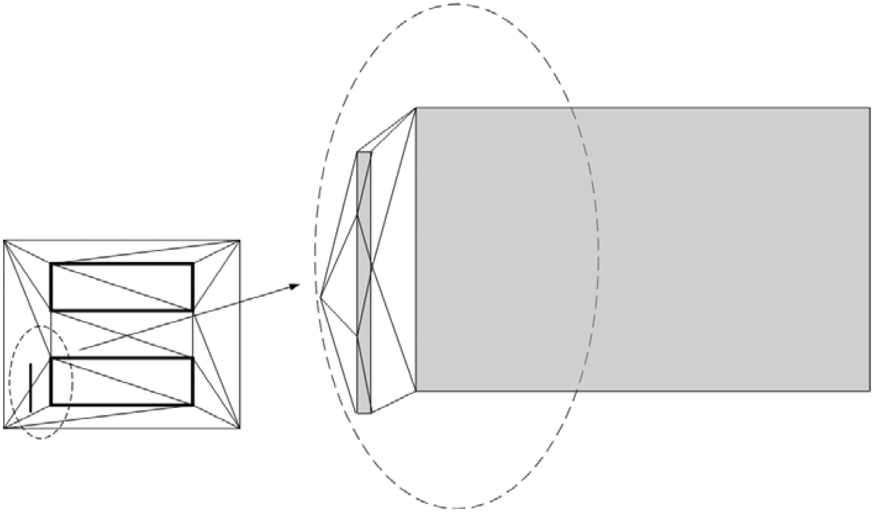
BTM
Once the tetrahedral network is generated, the sound can be propagated and traced in it by the BTM. The numbers recording the constrained conditions of the beam tracing are refreshed as the beam propagates. The beam starts from the tetrahedron containing the source and recursively traces based on the topology of the tetrahedral network. When a beam propagates from one edge or façade of a tetrahedron to another, it is cut by the boundaries of reachable areas. Encountering the constrained facade of buildings, the beam will be reflected. Diffracted beams are generated at angular points. For each pair of receiver and source, the paths between them can be continually acquired by the tree structure: find the tetrahedron containing the receiver, enumerate all the nodes in the structure and seek the target nodes meeting the requirement until the end. In the process of generation, records of the influenced tetrahedrons and edges or façades that are passed by the beam are required. When the target nodes are found, an effective 3D path from the source to the receiver is obtained.
Vehicle noise emission model
Studies30,31 reveal that when the traffic flow is heavy enough, the traffic flow can be considered an equal-value linear sound source, with every vehicle an omnidirectional point source. The vehicle noise emission largely depends on the type, speed, acceleration and other considerations. It also relates to the vehicles’ characteristics and the running conditions of the studied area. The modelling set of Guangzhou developed by Li et al. 32 is adopted in this method.
Noise propagation model
The road is divided into a series of sections, each of which is replaced by an equivalent point source located at its centre, and noise propagation calculations between each source and receiver are independent.
When noise is emitted from a vehicle, it propagates in the surrounding urban area. The sound field in the experiment is hemispherical, so the sound power

For any receiver P, the sound rays can be divided into four types: direct, reflected, diffracted and composite, the last of which is composite of reflected rays and diffracted rays. In any time step t, the sound intensity IP(W/m2) obtained from the ith vehicle can be described as the summation of all the paths’ contributions as

De Coensel et al. 20 detail the specific calculations of the four types of rays. It indicates that the accuracy of the calculation relies to some extent on the boundary conditions mentioned above, with higher thresholds (beam length, reflection times, diffraction times) providing a greater accuracy.
Accuracy and efficiency analysis of building subdivision and beam thresholds
To simulate the multiple reflections and diffractions in a 3D scene, the major challenge is to balance the accuracy and efficiency of the calculation. The thresholds of beam length, number of reflection and number of diffractions ultimately determine the error scale and the efficiency of the calculation. In a real environment, the discrepancies in the sizes of obstacles in 3D make obstacle subdivision and road traffic noise simulation difficult. Thus, the subdivision precision of the obstacles and the beam thresholds must be analysed.
Experiment description
Multiple reflections and diffractions are inevitable when noise propagation is simulated in 3D, so the efficiency and accuracy are very important. In the BTM, the thresholds of the beam (length, number of reflections and number of diffractions) determine the accuracy and complexity. In the process of spatial subdivision, the building subdivision precision also exerts a major influence on the accuracy and efficiency. Through a point source experiment, this paper analyses the effect of the above factors on the accuracy and efficiency of the calculation.
The Telecommunication Building (‘L’ shape, with varying heights of 24, 10 and 30 m) and the Building of the City Management Committee (of 17 m height) in Guangzhou’s Higher Education Mega Center were selected as the experimental area. The building layout and dimensions and the positions of the monitoring points (A, B) and source (S) are shown in Figure 3. The estimated reflection coefficient of the buildings and ground is 0.8. The source is emitted by an omnidirectional fixed-frequency generator of 630 Hz in 1/3 octave band of 0 m height. 7.5 m from the source, the SPL of a 0 m height receiver is 84.5 dB, and the background noise is 38 dB (measured at midnight, without interfering factors).
Building layout and positions of points (in m).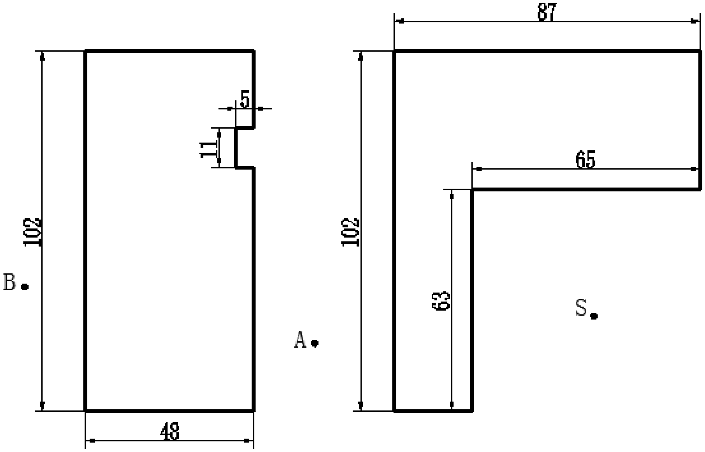
Analysis of accuracy of computation
Accuracy with different subdivision sizes and length thresholds
Using three reflections and two diffractions, the effects of the subdivision size and the path length of the beams on the accuracy were evaluated. Figure 4 shows the results of point A and point B at both 1 m height and 4 m height. Calculations were performed for five subdivision sizes (0.5, 1, 2, 5, 10 m) and six beam lengths (100, 200, 300, 400, 500, 600 m).
Effect of beam length and buildings subdivision precision on accuracy. (a) 1 m height for A, (b) 4 m height for A, (c) 1 m height for B and (d) 4 m height for B.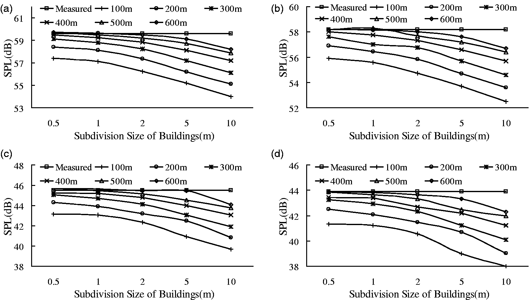
From the results of the experimental and numerical values, this analysis is as follows: (a) When all other parameters are equal, the calculation results come closest to the true values as the subdivisions shrink, and the errors logarithmically increase. The errors are negligible (less than 0.3 dB) when the size is less than 1 m because the more precise the subdivision is, the more elaborate the tetrahedral network is, which collects information on a finer scale to prevent the omission of beams. (b) Under the same conditions, the results logarithmically approach the true values as the length threshold increases. It is accurate enough (errors less than 0.3 dB) for receivers when the subdivision size is 1 m and the length of the beam is more than 500 m. Longer beam threshold and smaller subdivision size mean weaker acoustic energy and more elaborately tracing will be considered, which make the results more precise due to a more realistic simulation. When the length threshold is long enough, it exerts less influence on the error. (c) Under the experimental conditions, with a length threshold of 300–500 m and a subdivision size of less than 1 m, the accuracy would be within 1 dB, so the method can be effectively applied to the simulation of traffic noise propagation in a 3D environment.
Accuracy with different numbers of reflections and diffractions
The influence of the numbers of reflections and diffractions on the accuracy was studied using a 500 m length threshold and a 1 m subdivision size. Figure 5 shows the errors of point A and point B of 1 and 4 m height, respectively, following different numbers of reflections and diffractions. When the subdivision precision and thresholds are set appropriately (three reflections and one diffraction) the error will be no greater than 0.3 dB.
Effect of numbers of diffractions and reflections on accuracy. (a) 1 m height for A, (b) 4 m height for A, (c) 1 m height for B and (d) 4 m height for B.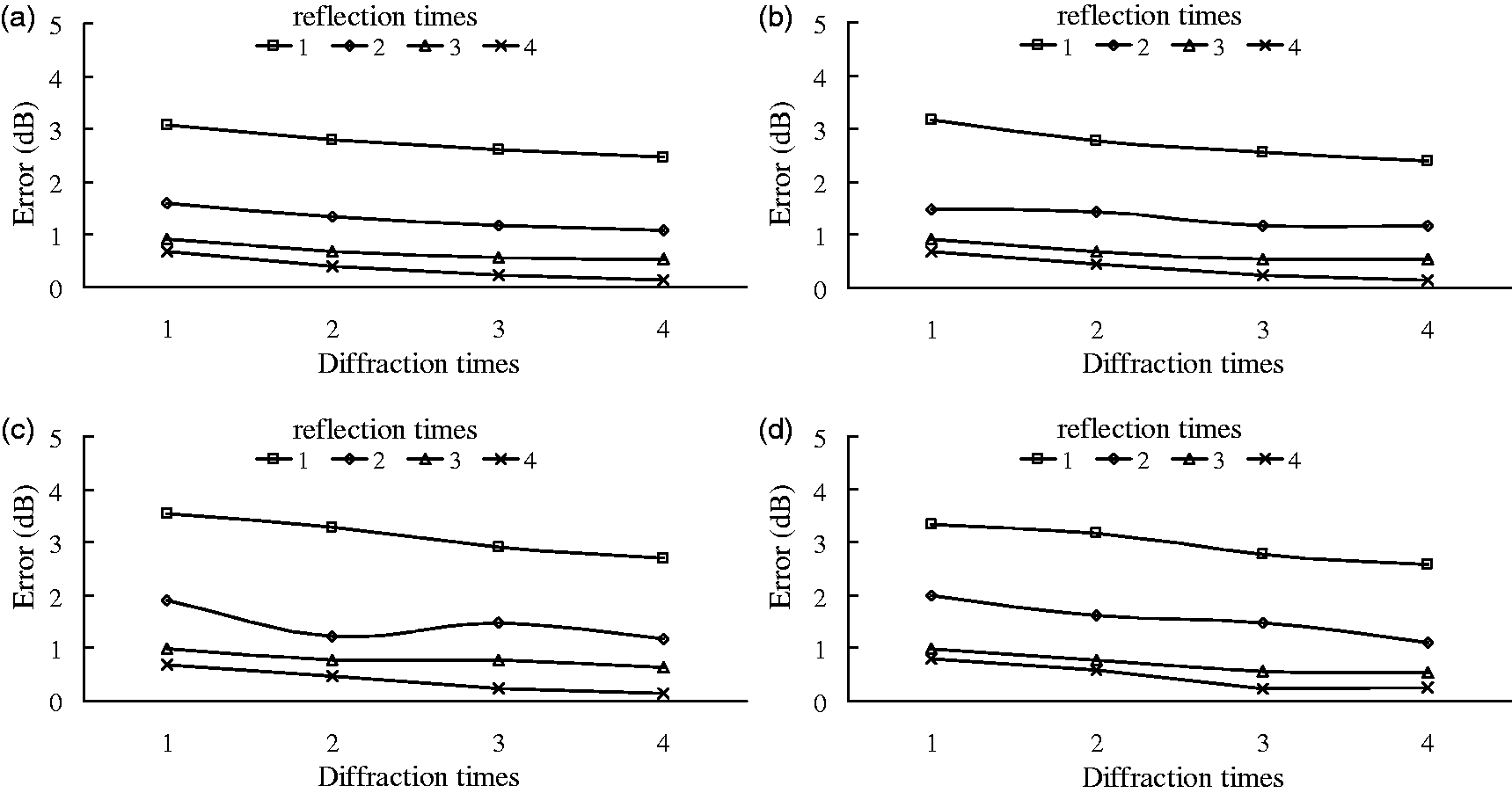
It can be indicated from Figure 5 that the number of reflections can be more influential than the number of diffractions in studied configuration, which can be seen at the example of point A (4 m): (a) With the same number of reflections, the errors curves vary slightly, with each additional diffraction causing the error to change by less than 0.5 dB. (b) However, with the same diffractions times, every additional reflection causes the error to change by an amount that decreases from 1.5 to 0.5 dB as the number of reflections increases from one to four times.
This phenomenon indicates that the contribution of diffracted rays to the accuracy of the method is quite small. Muer 33 showed that the calculation time exponentially increases with additional diffractions. Hence, the following calculations will be carried out using three reflections, one diffraction and a 500 m length threshold to match the accuracy and efficiency.
Efficiency analysis of computation
Time complexity of each step of the noise propagation calculation.
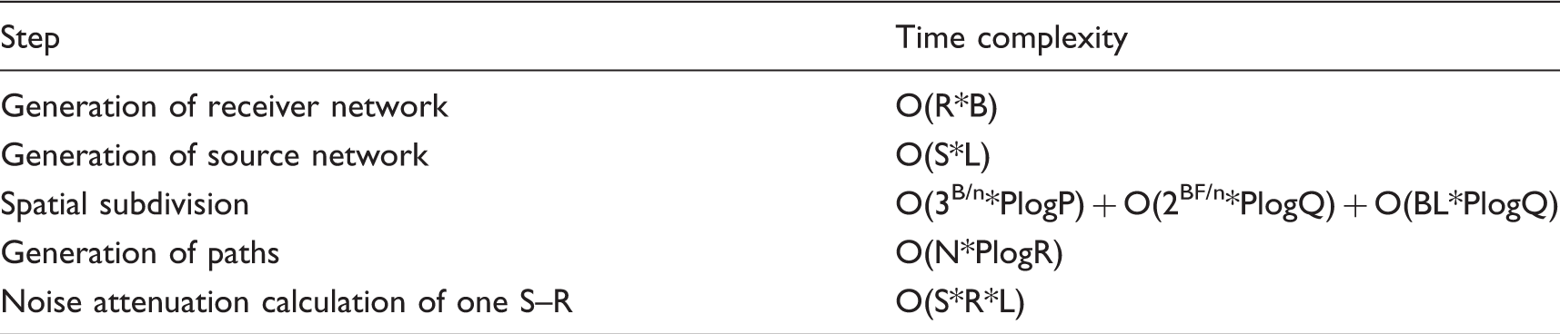
In Table 1, R is the number of receiver points, S is the number of sources on each road, B is the number of obstacles, L is the number of the roads, BL is the total number of edges of the obstacles, BF is the total number of facades of the obstacles, n is the subdivision size of the obstacles in 3D, N is the average number of nodes in the tree structures, PlogP is the time needed to insert a node, PlogQ is the time needed to recover an obstacle edge or facade and PlogR is the increase in time resulting from an increase in the tracking threshold.
Figure 6 shows the time expenditure of calculations using different subdivision sizes and length thresholds of the experimental area. The computation time exponentially increases with the subdivision precision and beam length thresholds. Under the experimental conditions, the relationship between the time (z) and the length threshold (x) can be expressed as z = 2.3986e0.6662x, and the relationship between the time (z) and the subdivision size (y) can be expressed as z = 1021.5 e−1.3604y. It is known that the largest components of the computation time are the spatial subdivision and the path generation, as shown in Table 1. Increasing the subdivision precision and length threshold causes the number of tetrahedrons in a spatial subdivision to geometrically increase, and as all these tetrahedrons are traversed in the process of path generation, the efficiency is dramatically reduced.
Effect of length thresholds and building subdivision precision on efficiency. (a) Different length thresholds, (b) different subdivision sizes.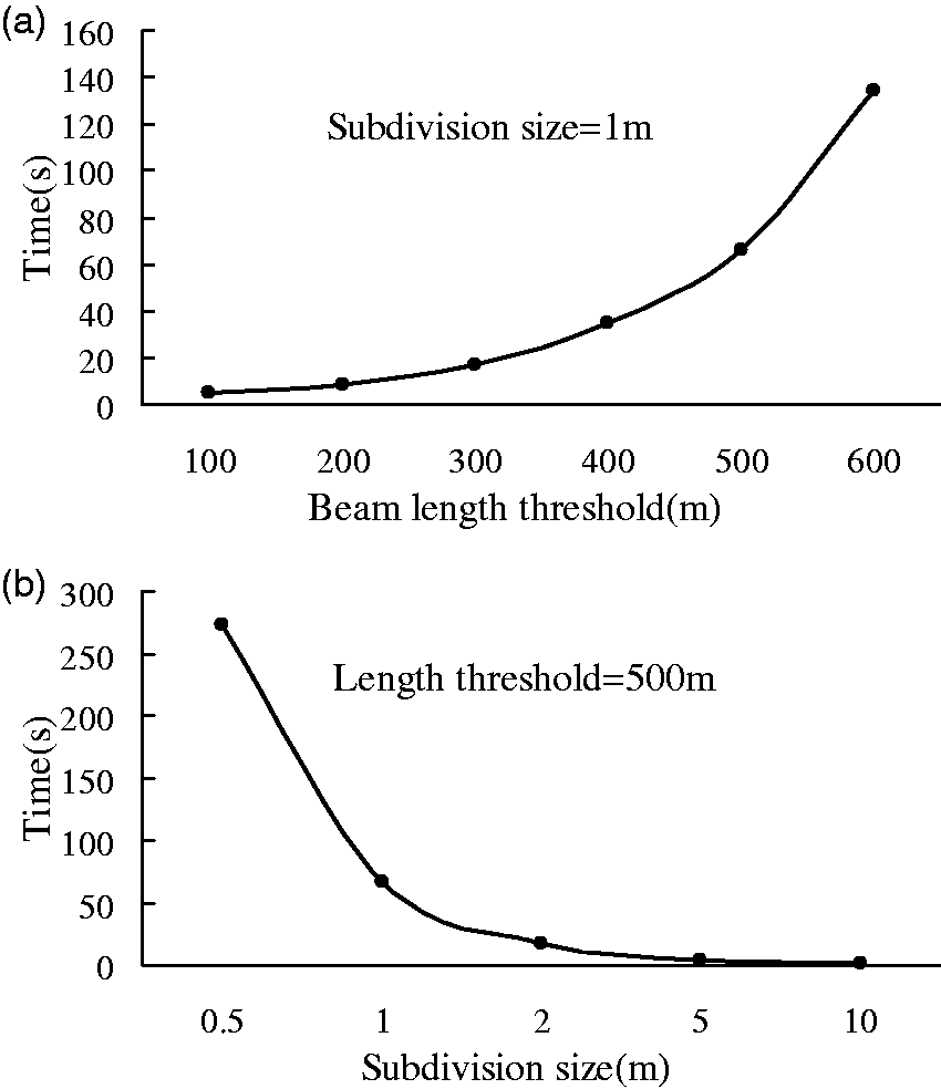
Accuracy and efficiency of re-subdivision and road discretisation
In a real environment, the presence of sound barriers and roads makes noise propagation simulation difficult. There is a stark contradiction between the subdivision of buildings, roads and sound barriers and the resulting precision. As re-subdivision and road discretisation are designed to solve the problem, the analysis of the precision of the subdivision of roads and the re-subdivision of areas with sound barriers is necessary.
Case description
Re-subdivision and road discretisation are employed in this method to solve the problems caused by the presence of sound barriers in the simulation of road traffic noise sources. As Figure 7(a) shows, research was conducted in a 250 m*250 m area to study the accuracy and efficiency resulting from the re-subdivision of barrier-related areas and road discretisation. The building layout and dimensions and the position of receiver R (20,-60) are given. Buildings A, B and C in the experiment are of heights 15, 10 and 20 m, respectively, and the distance between the sound barriers (of 195 m long, 0.1 m thick and 2 m high) and the road centreline is 5 m. Other relevant dimensions are displayed in Figure 7(a). The four-lane road with an average speed of 50 km/h has a flow of 300 vehicles/h. Heavy, medium and light vehicles account for 15, 5 and 80%, respectively. Figure 7(b) shows the noise distribution of the 4 m height plane through the calculation.
Sketch of case area and noise distribution of the 4 m height plane. (a) Sketch of case area (in m) and (b) noise distribution of the 4 m height plane (in dB).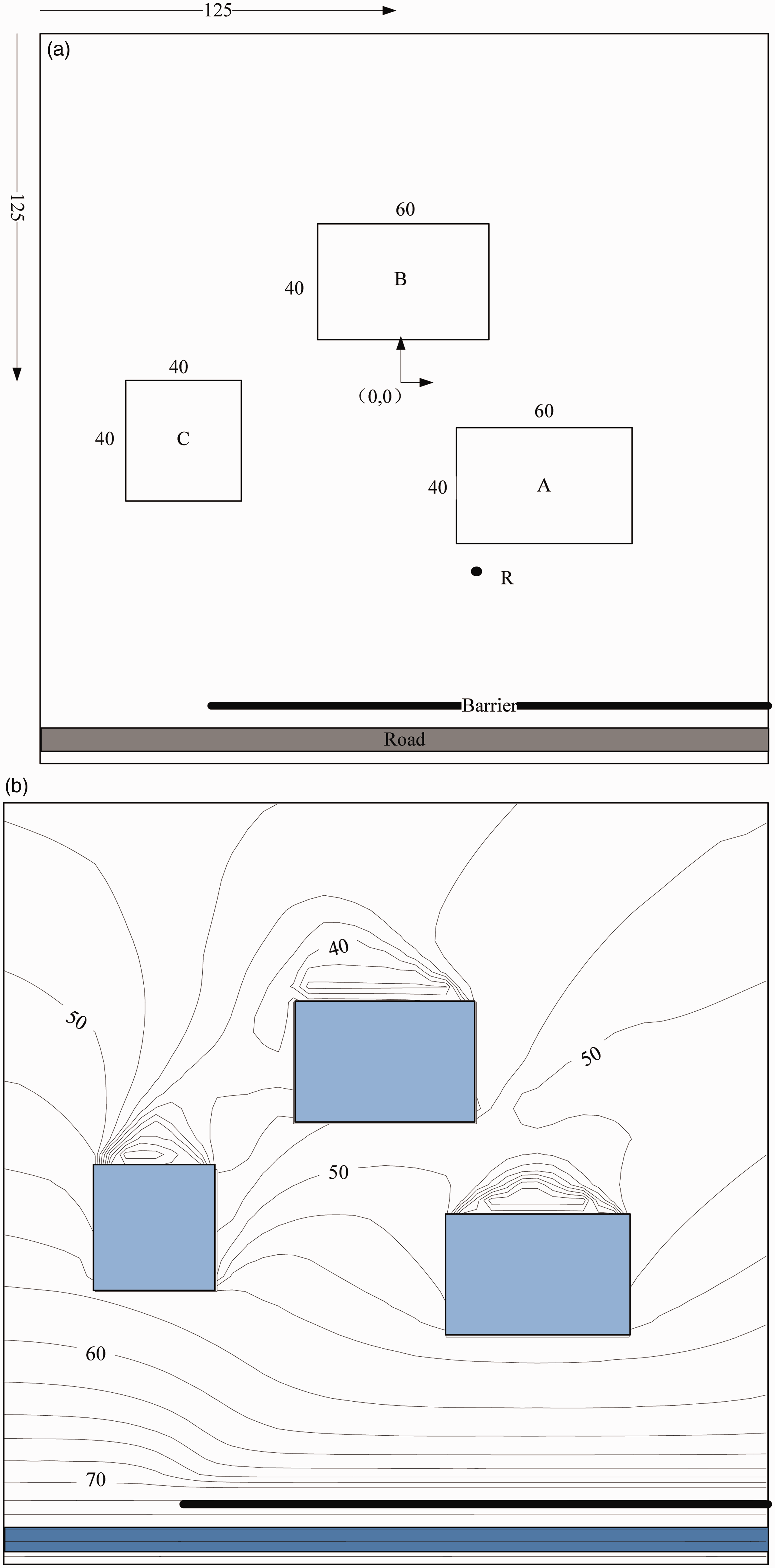
Analysis of the re-subdivision of the sound barriers
The trade-off between accuracy and efficiency caused by the discrepancies in the sizes of obstacles in 3D is handled by re-subdividing the sound barriers. First, the space with buildings and a road is subdivided into a tetrahedral network using an acceptable subdivision size (1 m). Then, the tetrahedrons influenced by the barriers are re-subdivided into more elaborate ones using a 0.1 m subdivision size, and the formed tree structures are correspondingly updated. Finally, the beams trace in the new structures and generate the paths.
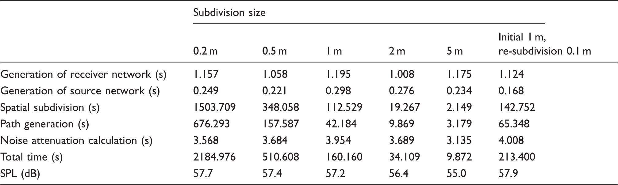
Figure 8 shows the time expenditure and the results of the calculation at the 4 m height receiver R (20, -60) with a 1 m road subdivision size in the case. It can be concluded that the re-subdivision sharply increases the efficiency with little cost to the accuracy. The time expenditure of two subdivisions is 213.4 s, which is slightly longer than the initial 1 m subdivision of 160.2 s and far less than the initial 0.5 m subdivision of 510.7 s. The result at the receiver is 57.9 dB, which is almost equal to that of the initial 0.2 m subdivision of 57.7 dB. Re-subdivision addresses the trade-off between accuracy and efficiency caused by the size discrepancy between obstacles while spending only approximately 1/10 the time as a single subdivision at the same subdivision size.
Effect of re-subdivision on efficiency and accuracy. (a) Time expenditure and (b) calculation results at receiver.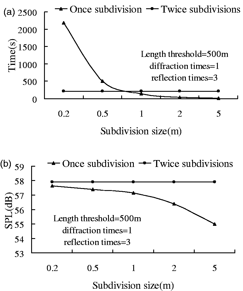
Comparisons of results (dB) and time expenditure of each step (s).
Analysis of road discretisation
Road traffic noise is usually considered a linear sound source, whereas the road is divided into multiple equivalent point sources in this method. The sign of the road subdivision is presented in Figure 9.
Sign of road discretisation.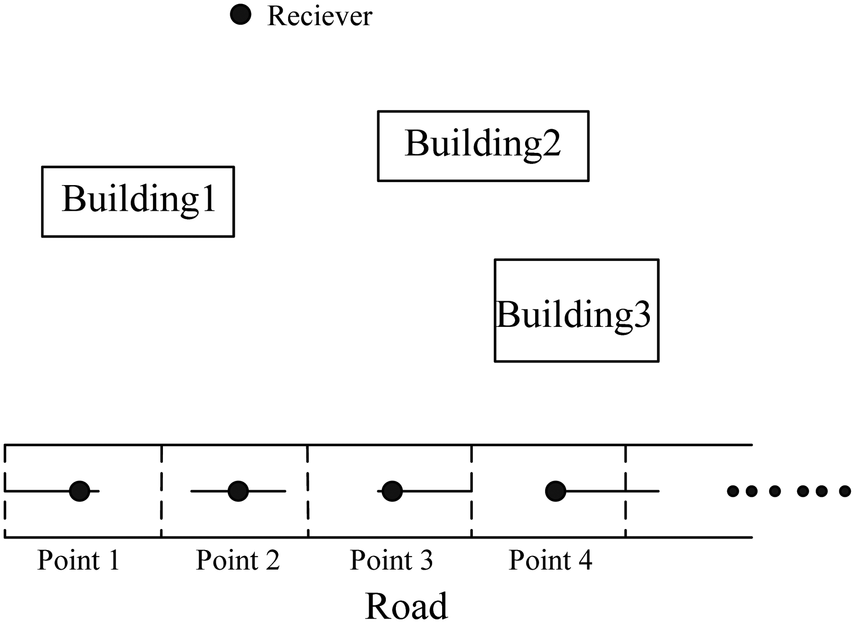
The influence of road discretisation on the accuracy and efficiency was studied for a building subdivision size of 1 m and a barrier area re-subdivision size of 0.1 m. As shown in Figure 10, the results of every single point for when the receiver R (20,-60) is set to different heights vary with the subdivision size. The conclusions of the analysis are as follows: (a) In the case, the noise abatement shows a disordered rule with low road subdivision precise (larger than 5 m). (b) The stability of the results increases significantly if the road is subdivided into equivalent point sources (as road subdivision size less than 3 m). There are about 10 dB D-values between the shadow area and direct area as the stable results of receiver are about 55 dB at shadow area and 65 dB at direct area. (c) When the subdivision size is less than 2 m, the calculation errors of the receiver at different heights are less than 0.5 dB.
Calculation results for receivers of different heights.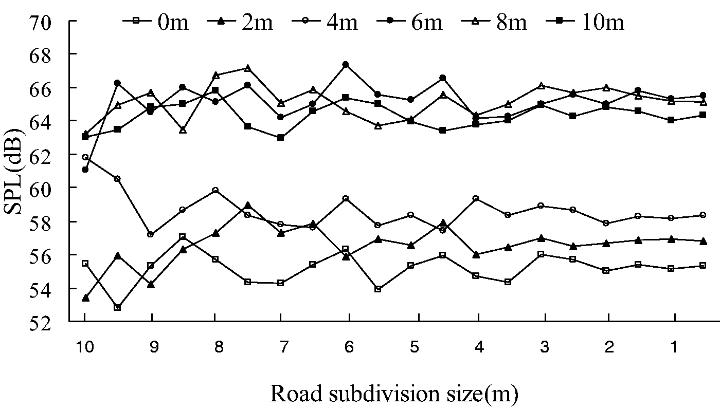
Figure 11 shows the time expenditure of calculations with different road subdivision sizes in the case. The computation time increases with the subdivision precision but much less significantly than with the building subdivision precision. Due to the locality of the road subdivision, the slight increase in the computation time of the processes of space subdivision and track generation do not significantly influence the efficiency of the calculation.
Time expenditures of different road subdivision sizes.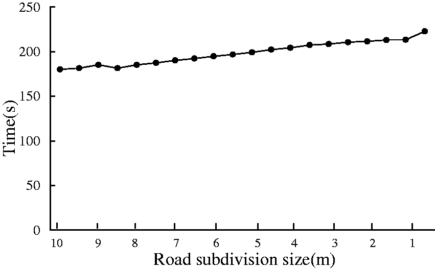
Conclusion
A method for traffic noise propagation calculation method based on beam tracing subordinated to spatial subdivision is presented in this paper to be employed in complicated noise attenuation calculations among 3D obstacles. And the method subdivides a whole space into tetrahedral networks with the goal of transforming the global search of beam tracing into a local one which can largely increase the calculation efficiency in 3D.
Analysis of accuracy and efficiency of the method from the perspectives of obstacle and road division precision and the beam thresholds (length, numbers of reflections and diffractions) have completed through experiment and case. Results show the error to be no more than 0.3 dB when the building subdivision precisions (0.5 m), road subdivision precision (2 m) and thresholds (a length threshold of 500 m, three reflections and one diffraction) are set appropriately. The largest components of the computation time are the spatial subdivision and the path generation. And the computation time exponentially increases with the subdivision precision (in the case, z = 1021.5 e−1.3604y) and beam thresholds (in the case, expressed as z = 2.3986e0.6662x).
It is original that re-subdivision of sound barriers is presented to handle the trade-off between accuracy and efficiency caused by the discrepancies in the geometric dimensions. Method with re-subdivision of the sound barrier ignored low-impact tetrahedrons and generates tiny tetrahedrons, which only slightly add to the workload of the beam tracing. In the case study, the sound barrier is re-subdivided by 0.1 m, resulting in a calculation time slightly longer than that of a single building subdivision size of 1 m and exhibiting almost the same calculation result as the subdivision of 0.2 m. The re-subdivision sharply increases the efficiency with little effect on the accuracy, spending only approximately 1/10 the time as a single subdivision at the same subdivision size.
Footnotes
Declaration of conflicting interests
The author(s) declared no potential conflicts of interest with respect to the research, authorship, and/or publication of this article.
Funding
The author(s) disclosed receipt of the following financial support for the research, authorship, and/or publication of this article: This work was supported by the National High Technology Research and Development Program (‘863’ Program) of China (2012AA121402) and the National Natural Science Foundation of China (11574407).