A multi-objective mixed 2/∞ robust output feedback control synthesis with regional pole placement constraints in a linear matrix inequalities framework is adopted for active low-frequency sound radiation control of an arbitrarily thick, rigidly baffled, simply supported, multi-layered piezo-composite circular panel. The adopted control system concurrently captures the benefits of both 2 transient control performance and ∞ robust stability in the face of external disturbances and system uncertainties. Also, the implemented volumetric sensing/actuation configuration avoids the typical problems associated with conventional (spatially discrete) piezoelectric sensor/actuator patches, where the total volume velocity can be effectively cancelled with the main contribution being to the long wavelength acoustic power emission. The elasto-acoustic analysis is based on the spatial state-space method in the context of exact 3D elasticity theory along with the Rayleigh integral formula where Neumann’s addition theorem is incorporated in the associated Hankel transform representation to arrive at a computationally efficient expression for the nonaxisymmetric pressure field within the acoustic half-space, valid in both near and far fields. Subspace system identification of the fully coupled structure–fluid interaction problem is performed, and the truncated modes are considered as multiplicative uncertainties in synthesis of the mixed-norm controller. Numerical simulations establish the ability of the implemented volumetric sensing/actuation methodology in cooperation with the multi-objective robust active control scheme for restraining low-frequency sound radiation from a /steel/PZT4 circular piezo-laminated plate, without provoking instability of the closed-loop system. Also, superior bandwidth frequency and tracking performance in comparison to the and controllers are observed. This work is believed to be the first such attempt to exactly model (and actively control) the 3D nonaxisymmetric acousto-elastodynamic frequency response of an arbitrarily thick, smart piezo-laminated circular plate in heavy fluid loading condition (i.e. without using any kind of far-field, low-frequency, and/or light fluid coupling approximations), with straightforward extensibility for any arbitrary through-thickness variation of distributed material properties.
Active abatement of low-frequency noise and vibration emitted from vibro-acoustic systems, as a complimentary approach to the inactive restraining techniques that are normally appropriate in the medium- and high-frequency range,1,2 has been a subject of great interest during the past few decades. Two main strategies are generally adopted, namely, active noise control3 and the active structural acoustic control (ASAC).4,5 In the more viable and practical ASAC method, error sensors together with a minimization procedure associated with a judiciously designated cost function are generally employed to manage sound radiation by specific actuation of tractable auxiliary forces (i.e. via shakers, electro/magneto-rheological, and piezoelectric materials) on the resonating structure. The piezoelectric materials are particularly used in new-generation high-performance smart structures for vibration and noise control owing to their low power consumption, lightweight, flexibility, wide dynamic range, and fast response time.6,7 Also, a wide variety of control strategies, such as velocity feedback control,8 optimal control,9,10 neural network control,11 adaptive control,12 and 13 and robust control14,15 theories, have been developed for active vibro-acoustic response control of oscillating fluid-coupled structures. Important among these control schemes are the controllers that have the key advantage of systematically assuring the robust performance/stability along with optimized vibration eradication in the face of uncertainties in the nominal system model and external disturbances.16,17 As a further step, the and control objectives can be unified in a single (mixed) time–frequency domain design framework, in order to simultaneously optimize system performance and enforce robustness constraints.18,19 Synthesis of such multi-objective controllers can expediently be achieved by employment of the linear matrix inequalities (LMIs)18,20 that provide algebraic representations of various control specifications and allow computationally efficient and systematic design of robust controllers by reducing the controller design into a standard convex optimization problem. Furthermore, application of extra robust regional pole placement constraints can cause ample satisfaction of both the stability robustness and the temporal performance requirements.21
Plates are one of the most extensively used structural components in numerous engineering, civil, martial, oceanic, and aerospace/aeronautical applications (e.g. building walls and floors, ship hulls, machine elements, ground-based or aerospace vehicle panels, and aircraft sidewalls). These structures can practically be modelled, to a first approximation, as a finitely bounded baffled panel.22,23 The literature review presented here will largely focus on the most pertinent contributions regarding the vibro-acoustic response control of flexible planar radiators of circular planform. In comparison to the rectangular plate geometry,24 far fewer authors have considered active acoustic radiation suppression of circular plates. For example, Fuller25 used directly applied oscillating point forces from electrodynamic shakers to study active suppression of acoustic transmission through a rigidly baffled clamped thin circular elastic plate excited on one side by a plane acoustic wave. He demonstrated that global attenuation of broadband radiated sound levels for low to mid frequencies can be attained with one or two control forces, regardless of system resonance condition. Subsequently, Metcalf et al.26 performed experiments to find good correlation between the analytical predictions of Fuller25 and their experimental measurements. Dimitriadis and Fuller27 theoretically explored the prospects of actively controlling sound radiation (transmission) from (through) a vibrating thin circular plate using surface-bonded piezoelectric actuator elements. They demonstrated that these types of actuators have great potential for controlling the vibration in distributed systems and consequently the control of sound radiation. Van Niekerk et al.28 presented an active (2 optimal feedback/feedforward) control methodology that reduces transient noise transmission through a thin circular plate set in a circular duct by employing two circular piezoceramic patches as actuators. Leniowska and Leniowski29 considered active extinction of the far-field acoustic pressure radiated by a fluid-loaded thin circular plate set in a finite baffle, through application of a point control force from an electromechanical shaker directly to the plate surface. Rdzanek and Zawieska30 investigated far-field acoustic radiation reduction from a vibrating clamped-guided annular plate under an external pressure, by direct application of a shaker clamped into the internal edge of the panel. Leniowska31 analytically studied active vibration Linear-quadratic regulator (LQR) control of a fluid-coupled baffled circular plate excited on one side by a uniform periodic force by using centrally placed circular-shaped piezoelectric PZT (Lead Zirconium Titanate, Pb[ZrxTi1-x]O3) actuator patch pairs. The results indicated that while the adopted control law provided a significant drop in the plate vibration, it is rather ineffective for noise attenuation. Leniowska32 examined the effect of the active vibration control strategy on the sound emission from a fluid-coupled circular plate set in a finite baffle using a point control force. Leniowska33 subsequently employed Simulink/MATLAB to investigate the effects of viscous damping, structural internal damping, and fluid loading on active acoustic radiation attenuation from a baffled, thin circular plate, under a constant-amplitude periodic force, by using symmetrically located circular piezoelectric actuators. Wiciak34,35 used numerical and experimental techniques to investigate active suppression of acoustic wave passage through a thin clamped circular plate baffled in one face of a water-filled rigid-walled aquarium, by using distributed surface-bonded square-shaped piezoelectric actuator elements. More recently, Johnson et al.36 studied acoustic radiation mode shapes of circular plates and used objective functions to target the most efficient radiation modes for reducing the radiated sound power.
The above brief literature assessment evidently shows that, although there are a number of research works that employ various control methodologies to investigate active acoustic radiation extinction from thin panels of circular planform, rigorous analytical or numerical solutions dealing with a (heavily) fluid-coupled smart circular piezo-laminated plate of arbitrary thickness appears to be missing. Consequently, in the current manuscript, we shall utilize the linear three-dimensional exact piezo-elasticity theory and the classical Rayleigh integral formulation,22 along with a multi-objective mixed robust output feedback control synthesis with regional pole placement constraints in a LMI framework,18 to fill this important gap in the literature. In this regard, the main scientific novelty of the suggested study with respect to the previous research works is not in the applied techniques themselves, but rather it resides in presenting a multi-disciplinary (fully coupled) theoretical approach that effectively combines the strategic advantages of these methods to tackle a currently unsolved practical problem in the field of ASAC. More specifically, the key contributions/advantages of the proposed model may be highlighted as follows:
Exploiting the linear elasticity theory along with the classical Rayleigh integral approach to arrive at an exact 3D acousto-elastodynamic solution for describing the forced nonaxisymmetric sound radiation from a fluid-coupled multi-layered smart piezoelectric circular panel of arbitrary thickness. Such solution is known to be much more accurate than the those based on the approximate 2D (Kirchhoff, Mindlin) plate theories22,23 that lose accuracy as the panel thickness to radius ratio increases.
Making use of proper Hankel transform representation and Neumann’s addition theorem to obtain a very useful computationally efficient and inclusive exact (single integral) analytical expression for the nonaxisymmetric pressure field within the coupled acoustic half-space that is valid in both near and far fields over the entire frequency range of interest, while avoiding the serious disadvantages of the semi-analytic and numerical methods (e.g. inaccuracy, computational intensity, mathematical ill-posedness, fictitious frequencies). To the author’s knowledge, all existing (thin-panel) models either treat only the axisymmetric sound radiation problem28,30–33 or study the nonaxisymmetric sound radiation based on various simplifying assumptions (e.g. far-field, low-frequency, and/or light fluid loading approximations).25,27,29
Applying the spatial state-space approach in tandem with a laminate model that allows for an arbitrary through-thickness variation (gradient) of distributed constituent material properties (FGM, FGPM), with no restrictions on the variations of stresses or displacements.
Implementing the LMI-based multi-objective mixed 2/∞ robust active control synthesis to simultaneously and effectively capture the benefits of both the 2 transient control performance (i.e. satisfaction of temporal requirements) and the ∞ robust stability (i.e. fulfilment of the frequency domain constraints) as a convex optimization problem in the face of external disturbances and system uncertainties (unmodelled dynamics).
Using a uniformly distributed piezoelectric volume velocity sensor layer perfectly matched with a constant force actuator layer in order to primarily sense and excite the first (piston-like) radiation mode of the oscillating plate.24 In this control configuration, the total volume velocity that is known to have the largest contribution to the low-frequency acoustic power emission can effectively be cancelled.37–39 Furthermore, the common problems frequently associated with the conventional spatially discrete sensors and actuators, such as the weight/volume/support requirements, line moment excitation effects,8 observability/controllability problems, and control spillover effects,4,40 are avoided.
Furthermore, the suggested model, which takes full account of the mechanical interaction between the sensor/host/actuator layers, is of imperative interest because of its intrinsic importance as a standard problem in vibro-acoustics. It is also of applied benefit for structural acoustics engineers interested in improvement of low-frequency sound radiation characteristics of thick piezo-composite smart circular plates in the face of uncertainties.15,19,41–42 These elements are of realistic concern in advancement of intelligent micro-electromechanical systems,43,44 for which precise movement control is essential. It can readily be combined with the classical passive control methods1,2,45,46 and/or expediently be augmented with multiple pairs of electroded piezoelectric actuator/sensor segments in a multi-input multi-output (MIMO) active control framework47–49 to effectively deal with the medium- and high-frequency acoustic radiation problems.1,2 Finally, the accessible set of numerical simulations can aid as the reference for evaluation of results acquired by the merely algorithmic or asymptotic methods.
Formulation
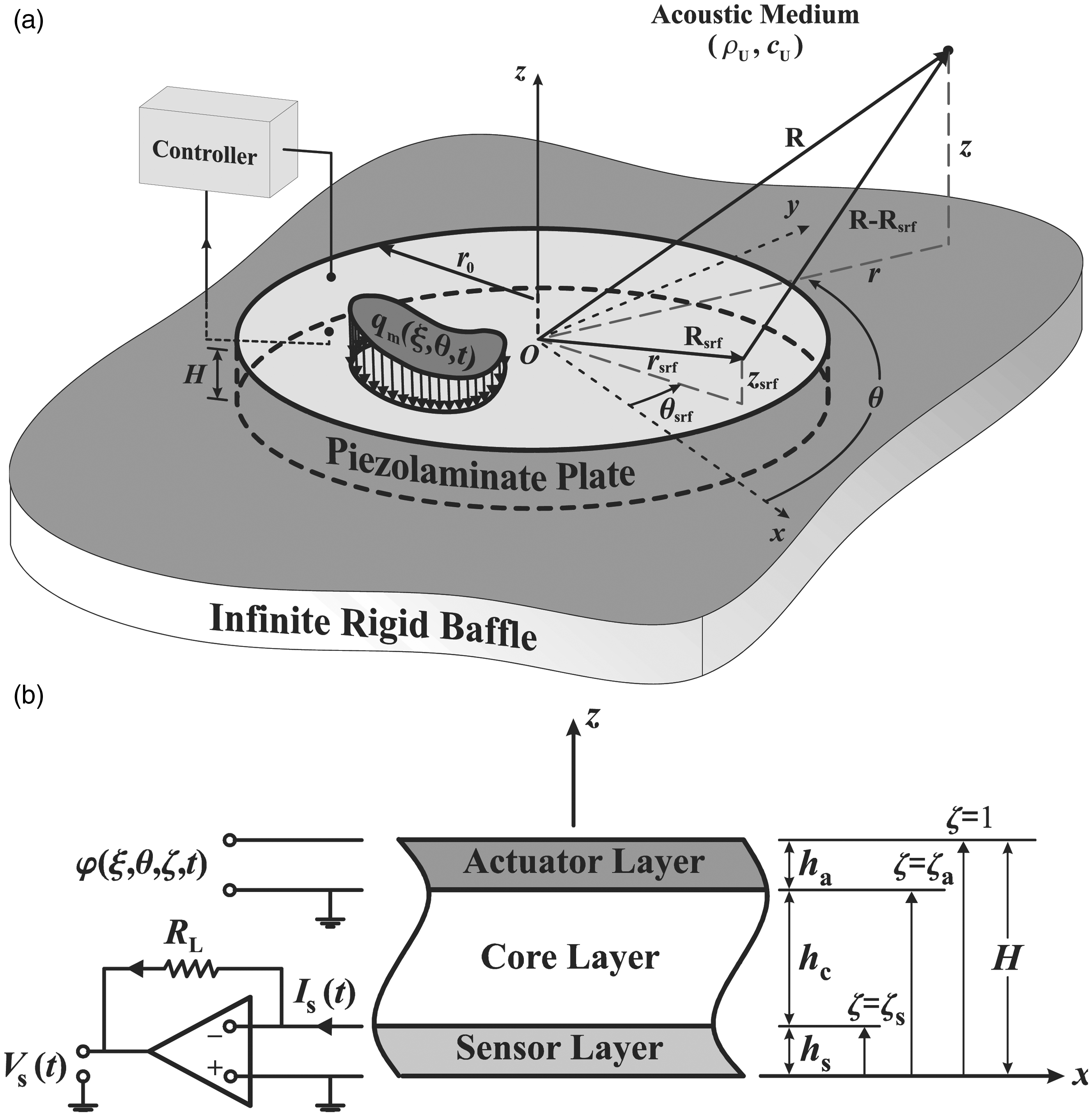
Consider a flat composite circular panel set in a rigid baffle, and in contact with neighbouring upper and lower acoustic fluid mediums of densities , as shown in Figure 1(a). It consists of a transversely isotropic circular base plate (radius , thickness ) bonded on its bottom boundary to an entirely electroded perfect volume velocity sensor lamina of thickness while it is perfectly matched on its top boundary with a constant-force evenly spread piezoelectric actuator lamina of thickness (see Figure 1(b)). The piezoelectric actuator lamina is basically the reciprocal of the volume velocity sensor lamina, capable of applying a uniform distributed force over the top boundary of the base layer. Such matched distributed actuator/sensor pair configuration will be seen later (section ‘System Identification and Controller Design’) to primarily measure and excite the first radiation mode of the composite panel.37–40 Also, the associated control system, which essentially reduces the total volume velocity, is then anticipated to attain decent mitigations in the low-frequency sound power radiation, while avoiding the control spillover effects.4,23,40 Before outlining the control method, we shall briefly describe the basic elasto-acoustic model50,51 (i.e. the governing equations for the piezo-laminated circular panel structure coupled with the surrounding fluid mediums) in the next two subsections.
(a) Problem geometry and (b) the smart sandwich plate.
Piezo-composite panel
With the lack of free charge density and bulk forces, the basic linear constitutive equations, along with the equations of motion and electric equilibrium, are specified in the cylindrical coordinate system as
where is the movement vector, is the piezo-material density, is the Cauchy stress matrix, and , , and , are the strain, stress, electric displacement, and electric field vectors, correspondingly. Also, ϕ is the electric potential, and the piezoelectric coupler matrix, e, and the elastic/dielectric constant material matrices , and as well as expressions for the pertinent movement and stress elements with regard to proper stress and movement functions are given in the Appendix 1. By straight use of the these expressions in the governing equation (1), one attains the ensuing two totally uncoupled state equations
in which and , and the matrix coefficients are given in Appendix 1. Also, adopting the simple elastic support conditions at , as proposed by Ding and Xu52,53 (i.e. ), one can assume the subsequent vector results for the piezoelectric layers
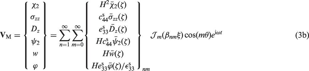
where , denotes the mth-order cylindrical Bessel Function of the first kind, and are the nth roots of and , respectively, ω is the frequency, , , and , , are piezoelectric parameters of the sensor lamina. Straight replacement of results from equations (3) in the state equations (2), leads to the subsequent modal state relations
where and are modal state vectors. Also, the matrix coefficients are given in Appendix 1, and the index ‘‘ is associated with the sensor and actuator lamina, respectively.
Next, by using the approximate laminate model assumption, one can advantageously split piezoelectric actuator/sensor laminae into and amply thin identical-width sublayers, correspondingly.54 Also, as a result of solving state equations (4), the state parameters at the subjacent boundary of sensor and actuator laminae can be linked to those on the top boundary in the form24
where, , , and are partial transfer matrices connected with sensor/actuator laminae.
Following a similar procedure for the core layer, with the associated constitutive relation (see Appendix 1), the associated state equations can be expressed using suitable movement and stress functions as
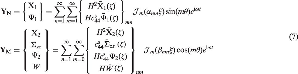
where , , W is the transverse movement constituent, the matrix coefficients are provided in Appendix 1, and the associated state vectors are expanded as55
Direct substitution of above expansions into the state equations (6) leads to the following modal state equations
where and are the associated modal vectors, and matrix coefficients , are given in Appendix 1. Also, by adopting the laminate approximate model once again, and with direct solution of state equations (8), the state parameters at the subjacent boundary of the transversely isotropic layer can be linked to those on the top boundary in the form24
in which and denote the partial transfer matrices connected with the transversely isotropic core layer, with being the number of fictitious layers.
Next, the electrical surface conditions on the topmost and lowermost boundaries of the piezo-actuator lamina are correspondingly given as
with the prescribed electrical potential magnitude being expressed as (see equation (3b))
Successive grouping of equations (5b) and (10), after some mathematical managements, leads to
where denotes the ‘mechanical constituent’ of vector , and
where refer to the entries of the partial transfer matrix , , and . Similarly, the electrical surface conditions associated with the piezo-sensor lamina are written in the form54
Consequently, by benefit of equations (5a) and (13), one has
in which where refers to the entries of the transfer matrix , , and . Lastly, the state results (9), (12), and (14), may be united to arrive at the final overall transfer relation for the entire laminated smart structure
where represents the general transfer matrix.
Sound radiation and fluid/structure coupling
Following the standard procedure,22 for a rigidly baffled flat area, S, oscillating with the transverse acceleration, , in a harmonic manner (see Figure 1(a)), one can make use of the classical Rayleigh integral formula for obtaining the sound pressure at the field location R within the neighbouring acoustic half-space
where refers to the liquid density, denotes the acoustic wave number, c signifies the speed of sound in the half-space fluid, is an arbitrary point on the vibrating surface (,), and indicates the separation between the receiver and source locations (see Figure 1(a)). Subsequently, by making use of the fifth relation in equation (3b), the complex harmonic pressure fields at any field point in upper () and lower () acoustic mediums (after some manipulations) can be obtained in the form22,24
in which
where , and.
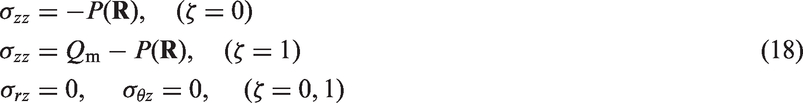
Now, supposing that the piezo-composite plate is acted upon its top surface by a distributed harmonic normal mechanical load of general form, , as depicted in Figure 1(a), the structure/fluid coupling conditions that must hold at the subjacent and top plate/fluid boundaries are written in the form
where the load amplitude, , is expanded as
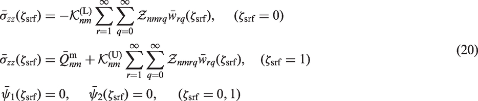
Subsequent use of expansions (3b), (17), and (19), in the surface conditions (18), after using the classical orthogonality relation in cylindrical coordinates, and with some tedious manipulations, leads to
where , , and
in which Thus, by exploiting the surface conditions (20) in equation (15), one ultimately obtains the linear matrix system
in which the matrix is provided in Appendix 1, and
where the constants are truncation numbers, and where (i = 1,2,3,4) refer to the entries of electric load vector .
Evaluation of quadruple integral and the radiated sound power
The Rayleigh integral has been adopted as an alternative to the finite and boundary element solutions of acoustic boundary value problems.56–58 Unfortunately, due to presence of singularities,59,60 the Rayleigh integral (equation (16)) is not actually responsive to direct numerical calculation of the near-field pressure, especially at high frequencies.39 This difficulty can be circumvented by following the mathematical treatment presented for example in the literatures,59,61,62 where the traditional Hankel transform (cylindrical wave) representation of the singular term (spherical wave) is adopted;63 i.e.
where, when should be replaced by . Also, by virtue of Neumann’s addition theorem in cylindrical coordinates64
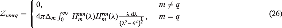
with and . Thus, by making use of above approximation in equation (21), changing the order of integration, and using the classical orthogonality relations of transcendental functions, one ultimately arrives at the computationally efficient single integral expression
where
The integral within the limits in equation (26) should be recognized as the Cauchy principal value integral along the real axis in the complex variable plane.65 Accordingly, the integral in the right hand side of equation (26) can advantageously be decomposed into59,60
The first integration can readily be evaluated using a standard Gaussian quadrature scheme.66 However, the second integration interval should be truncated at a certain wave number, , beyond which the kernel of integral decays very rapidly, and the contribution to the integral is negligible.60
The radiated sound power could readily be determined by integrating the acoustic intensity on the vibrating circular panel surface in the form22
where ‘*’ denotes the complex conjugate of a complex number. Thus, employing equations (3b) and (17) in equation (28), results in the expression for the radiated acoustic power in convenient matrix form as
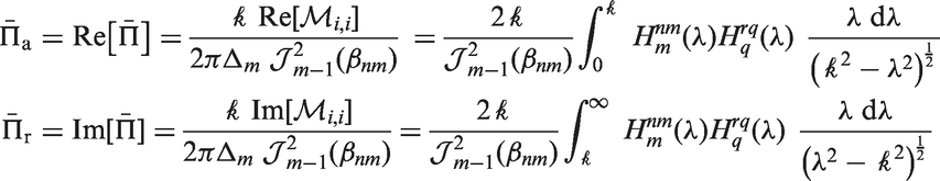
where is the modal displacement coefficient vector, ‘H’ denotes the Hermitian transpose, and the entries of the radiation impedance matrix, , are denoted by . Also, by making use of the so-called modal reference sound power, (where S is panel area, and denotes normal velocity of the nth panel mode), the standardized modal sound power, can be written in terms of the radiated modal acoustic power, , in the form65
where, by keeping decompositions (27) and (30) in mind, the standardized active and reactive sound powers are respectively defined as62
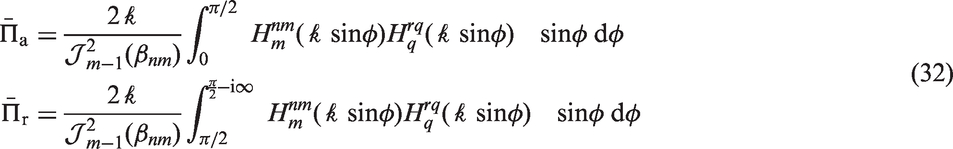
where ‘Re’ and ‘Im’ denote the real and imaginary parts of a complex number, respectively. Furthermore, by using the trigonometric substitution , the square root singularity in equations (31) can advantageously be removed, giving rise to the computationally efficient final expressions62
Volume velocity control and sensor voltage
Technological advances in production of smart panels with collocated and dual sensor–actuator transducer pairs has stimulated the development of light, compact, and noninvasive control systems that are very effective for eradication of tonal or broadband random acoustic disturbances.23,67–69 Also, the dominant contribution to sound power radiation from the panel at very low frequencies is known to be linked with the (strongly radiating) first radiation mode (characterized by a piston-type or monopole behaviour) which includes a combination of structural modes with nonzero volume velocities, commonly referred to in the literature as the ‘volumetric modes’.36–39,68,70 A fairly effective method in active suppression of low-frequency acoustic radiation for prediction of the first radiation mode magnitude is to use uniformly spread piezoelectric sensor materials which essentially respond to the velocity distribution associated with such radiation pattern.37,38,40 Therefore, a single-input single-output (SISO) volume velocity control system38,40,71 employing an integrated piezoceramic sensor layer collocated with a constantly distributed volume velocity (uniform force) piezoelectric actuator layer (see Figure 1(b)) can be advantageously configured to effectively reduce the total volume velocity vibration of the panel at such low-excitation frequencies.23,24,37–40
The electric charge accessible through the closed-circuit electrodes of the sensor lamina may be determined by simple integration of z-component of electrical displacement upon the electrode surface area,72 i.e.
Also, the voltage signal generated by the sensor lamina is linked to the volume velocity of emitting surface (output current of piezoelectric sensor, through the simple relation73
where is the leakage resistor of the current amplifier (see Figure 1(b)). This output voltage is returned back to the control unit which produces a feedback voltage for the piezo-actuator lamina.
System identification and controller design
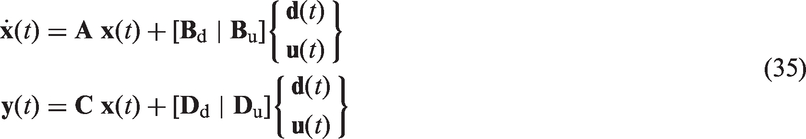
At this point, we shall apply the N4SID subspace-based estimation algorithm74 provided in MATLAB® System Identification Toolbox75 to identify the system and approximate state matrices for the complete coupled fluid–structural problem from sensor/actuator (output/input) voltage data of our numerical simulations, in the nth-order state-space form
where the vector is the actuator voltage, is the sensor voltage, is the state vector, represents the mechanical disturbance, and the matrices , ,, , , can be readily recognized based on the input/output vectors .
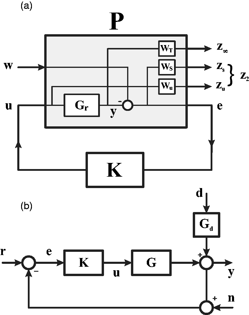
Next, we shall follow the procedure in Skogestad and Postlethwaite76 to formulate the mixed-norm controller synthesis problem in the general control framework. Here, it should be noted that, as and control methodologies are standard tools in the control community, there is not a vital need for detailed re-description of this mathematically intensive subject, where the interested reader is referred to the literatures.13–21,77–83Figure 2(a) shows the standard configuration of the multi-objective robust output feedback controller where is the generalized plant comprising the arrangement of all dynamics required for design and synthesis of the generalized controller based on the measurable error signal e, while w denotes the exogenous input vector to the generalized plant (e.g. reference signal, r, disturbances, d, noise,n, etc., see Figure 2(b)). The regulated output channel is associated with the performance and the regulated output channel is related to performance. Also, to get a meaningful controller synthesis problem, one generally has to include the frequency-dependent weights (reflecting the requirements on control objective), (imposing restrictions on the actuator signal), and (known as the multiplicative uncertainty weighting function) in the generalized plant. Moreover, the nominal plant, , as the approximate model of the coupled fluid/piezolaminate panel system, which relates the actuator input voltage to sensor output voltage, can readily be obtained from the estimated system matrices (see the state equations 35) in the form
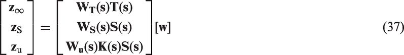
where I is the identity matrix. Consequently, for generalized plant in Figure 2(a), the relation between the regulated outputs and the input of interest (selected as a reference-like signal) is given by
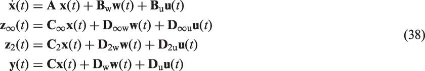
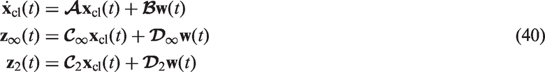
where ] is the closed-loop sensitivity function defined as the transfer function from w to error e, and is the complementary sensitivity function which is the transfer function from w to output y. Subsequently, a multi-objective output-feedback synthesis for our SISO linear time-invariant (LTI) system (plant) may be considered with the following state-space realization18
(a) The multi-objective mixed output feedback control problem and (b) block diagram of the closed-loop acousto-elastic system.
Our main objective here is to design a dynamic output feedback controller that minimizes the norm of the closed-loop transfer function from w to and keeps the norm of the transfer function from w to under some appropriate level. Accordingly, the state-space representation of the synthesized output-feedback controller is described by
where is the controller state variable. Thus, the closed-loop state-space representation containing performance and robustness channels for the generalized plant and controller is presented as
in which denotes the closed-loop state vector, and
and control performances
Let be the transfer function from w to with the realization (). Also, let represent the norm of the stable transfer matrix , defined in the frequency domain as
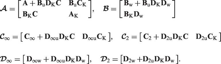
where is the maximum singular value. The constraint (where ) can be supposed as a disturbance rejection performance as well robust stability of closed-loop system. This particularly ensures that the closed-loop system remains stable for all perturbations w. Based on the Bounded Real Lemma,17 there exists a unique positive definite matrix such that the following matrix inequality is satisfied
Next, let be the transfer function from w to with the closed-loop realization (). Supposing that is stable and , the norm of is defined as
Also, recall that this norm can be computed as , where solves the following Lyapunov equation21
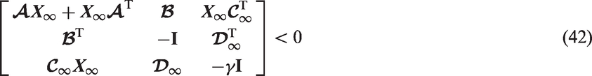
It is readily verified that (), if and only if there exists satisfies
Consequently, using Schur complements for above inequality, is equivalent to the existence of two symmetric matrices and such that
Regional pole constraints and multi-objective output feedback problem
The transient response of the system may be tuned by closed-loop pole placement in the convex left-half region of the complex plane within the framework of LMI, described as
where and M are fixed real matrices, and the ‘star’ superscript denotes complex conjugate. Also, the pole placement constraint is satisfied if and only if there exists a symmetric matrix such that21
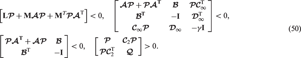
where and denote the entries of the matrices Land M. Here, the primary objective is to minimize the radiated sound power which will be described by the norm of over all output-feedback stabilizing gains that enforce the and pole placement constraints (i.e. ). This is equal to minimizing the over all matrices , , , and satisfying (42), (46), and (48) objectives. To recover convexity in the LMI framework, all specifications must be enforced by seeking a single closed-loop Lyapunov function where the symmetric matrix satisfies18
With the above equation imposed, our multi-objective synthesis problem can be further reduced to minimize over and subject to the LMI constraints
Robust stability design and closed-loop performance specification
Modelling errors are unavoidable when a plant is identified either theoretically or experimentally. A multiplicative unstructured uncertainty model seems to be a good choice for treating the model truncation error due to the negligence of high-order residual modes (i.e. avoiding spillover effects). Thus, the relation between the actual model of the system, and the reduced-order nominal model, can be written as
where is the frequency-dependent multiplicative uncertainty weighting function which is used to normalize uncertainty band, and represents the dynamics of neglected higher modes with In order to assure the latter inequality, the weighting function should be selected to cover the upper bound of uncertainty, which comprises the difference between the actual system FRF and the nominal model, in the from
According to the small gain theorem, to ensure the robust stability of the closed-loop system against multiplicative uncertainty, the following norm inequality must be satisfied17,76
In the mixed-norm robust controller synthesis, the closed-loop performance can be obtained by minimizing . Here, the objective is to achieve a high disturbance rejection by limiting the closed-loop sensitivity function, over the control bandwidth.77 Also, noting that the actuator control signal cannot be boundless, the control effort u should be appropriately confined for proper controller realization. Thus, one should limit the corresponding control effort described by . In particular, to minimize the effect of the exogenous disturbances in the controller bandwidth frequency interval, a low-pass filter should be used to weight . Furthermore, to avoid controller saturation as well as reduce the possibility of residual mode excitation, a high-pass filter can be used for weighting the function . Therefore, the desired performance of the output feedback controller can be achieved if the following mixed sensitivity norm is minimized.
Numerical examples
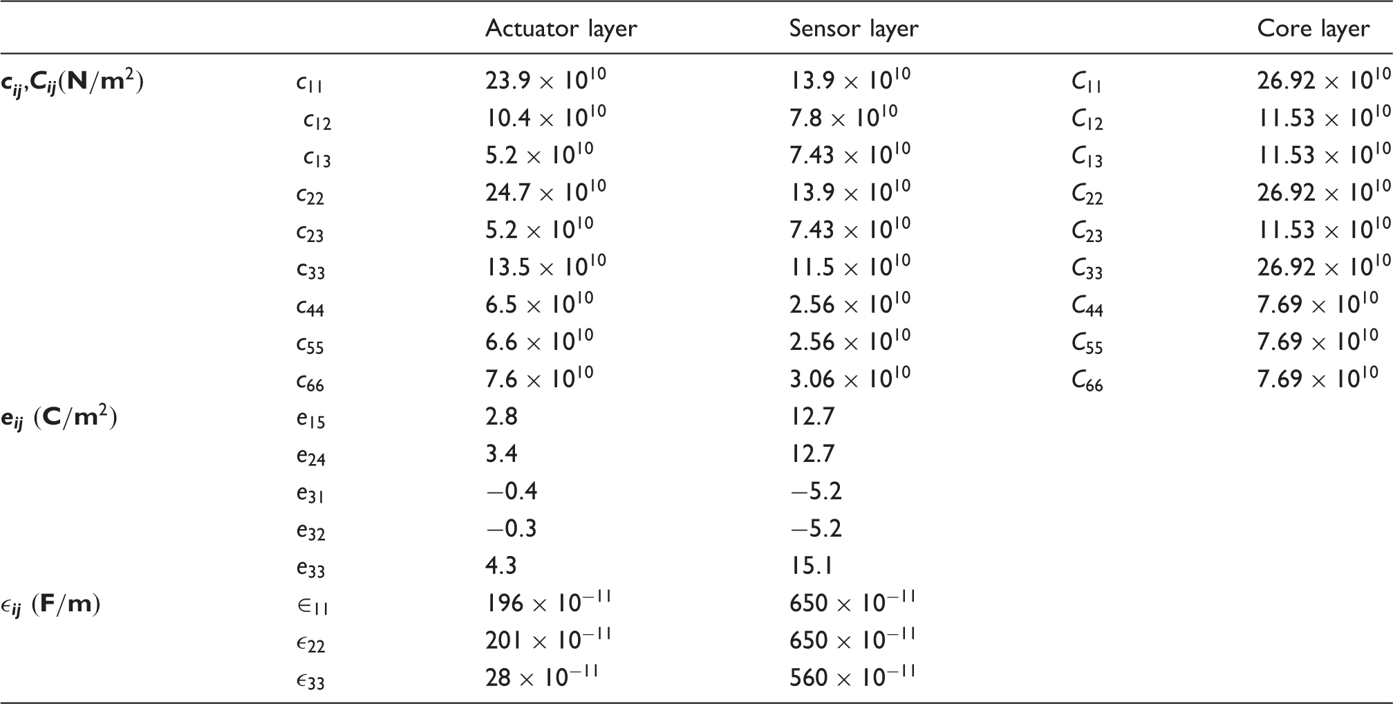
At this point, we shall consider some numerical simulations. Noting the numerous input variable presented here, besides our computational restrictions, we shall focus on a simple problem. Therefore, the core material is supposed to be fabricated from a single lamina = 1) of isotropic steel with , and the physical properties as given in Table 1. The sensor and actuator laminae are similarly supposed as single-lamina , ), made of /PZT4, , with their physical properties as provided in Table 1. The acoustic mediums are assumed to be water at ambient temperature (). An expansive Mathematica® program was written to calculate the response spectra of the structure–fluid interaction problem through solving the linear system of equations (22) with a maximal truncation parameter of . Since the functions in the integrands of equations (17b), (27), and (32) are known analytically, the classical Gaussian quadrature66 appears to be the most suitable (accurate) numerical method of integration, keeping in mind the speed of modern computers. Accordingly, the double integral in equation (17b) can be numerically evaluated by using the two-dimensional Gauss–Legendre quadrature with quadrature points, while the first and the second parts of the single integrals in equations (27) and (32) may be evaluated by employing maximums of and quadrature points, respectively.
Physical properties of the constituent materials.
Actuator layer
Sensor layer
Core layer
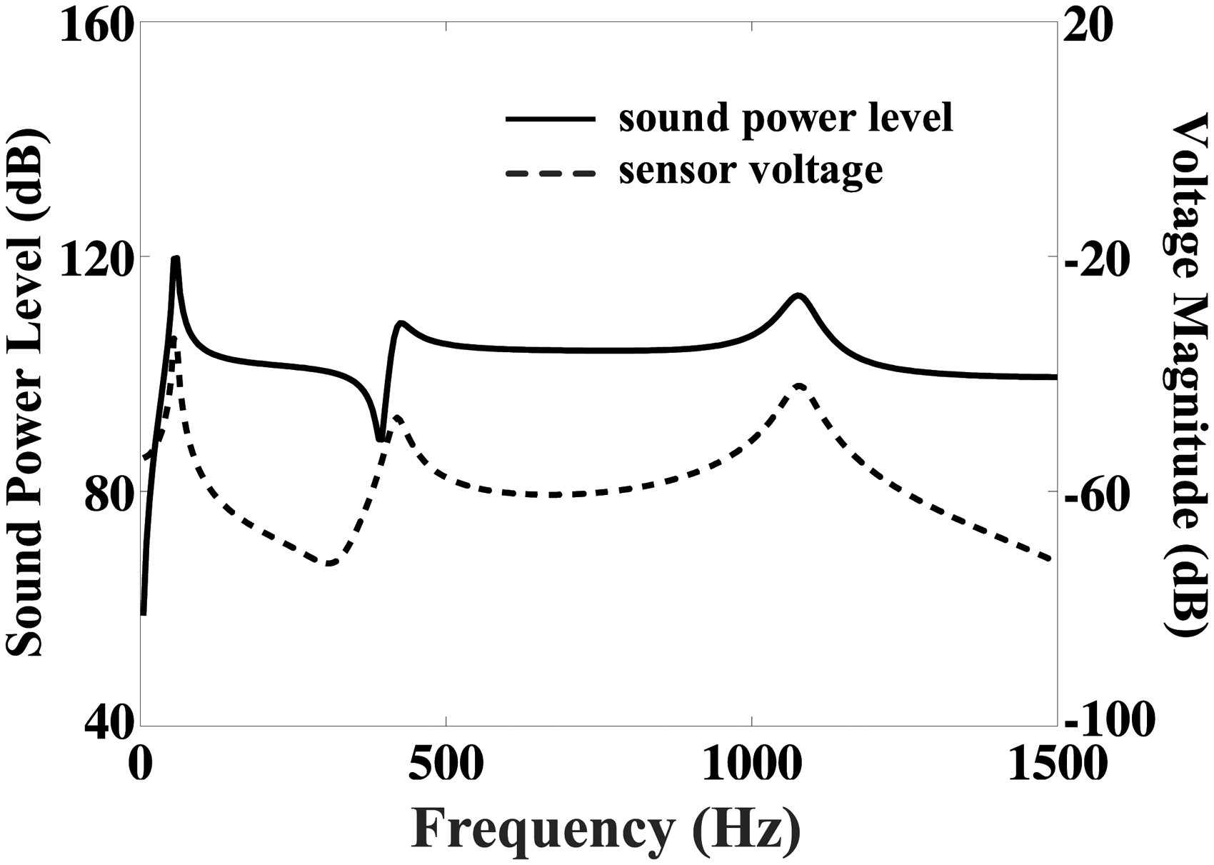
Here, it should be noted that fortunately the (weak) singularity present in the integrand of equation (17b) is well behaved enough so that numerical instability is not an issue when using the Gauss–Legendre quadrature algorithm (i.e. the denominator function g does not practically vanish identically). Furthermore, as the upper bounds of the second integrations in equations (27) and (32) are the symbolic ‘∞’, one should adopt a simple trial and error procedure to select proper fixed large numbers for the upper limits (i.e. by increasing the numerical values of the upper bounds, and look for stability of results). Lastly, Figure 3 plots the radiated sound power level22 as calculated from based on equation (29) with , and the volume velocity sensor voltage as calculated from equation (34) with Good correlation is obtained, which implies the effectiveness of the selected volume velocity sensor configuration in sensing the radiated power.
The correlation between the calculated radiated sound power level and the volume velocity sensor voltage.
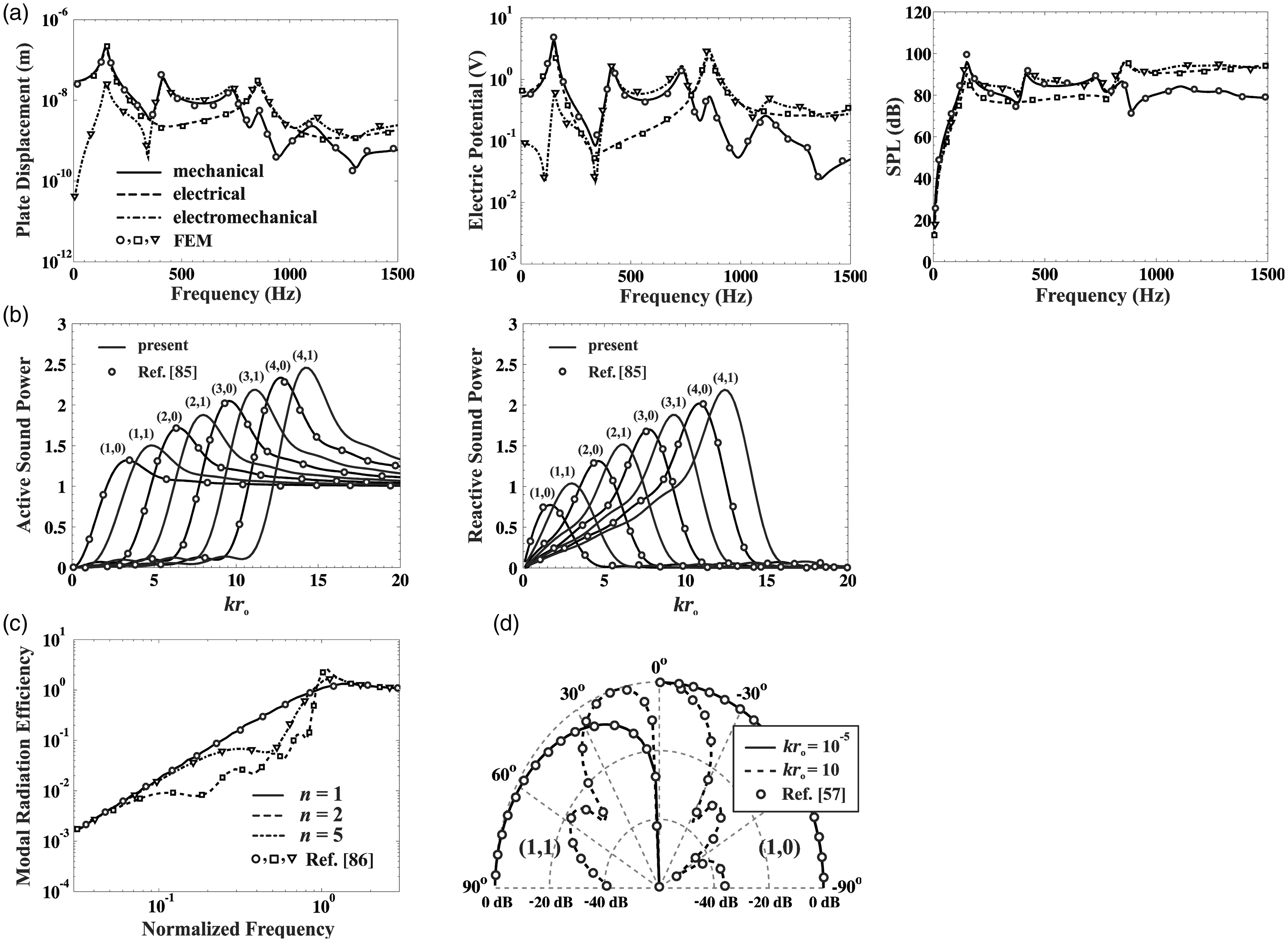
Before presenting the main results, we shall rigorously verify the overall accuracy of the proposed elasto-acoustic model. Accordingly, we initially treat a sandwich /steel/PZT4 water-immersed thick functionally graded piezolaminate circular plate with a material gradient exponent of 0.75, and = 0), under any one of the subsequent external excitations: a transverse harmonic (nonaxisymmetric) sectorial mechanical distributed load N/m2), a uniform harmonic voltage imposed on an annular region on the top surface of actuator lamina , and a nonaxisymmetric electro-mechanical harmonic excitation composed of simultaneous applications of the latter two loads. Figure 4(a) (i.e. the first row subplots in Figure 4) displays the good agreements obtained with the finite element method (FEM)84 results for the calculated displacement response and the electric potential at the observation point () on the bottom boundary of the intelligent plate. Also seen is the good agreement obtained for the radiated sound pressure level (SPL) at the observation point () in the upper acoustic medium. In the finite element model, about 3000 20-node piezo-brick elements (C3D20RE) were used for the top and bottom piezoelectric laminae, while about 2000 20-node brick elements (C3D20R) were employed to model the steel sheet. Also, a total of about 150,000 10-node tetrahedron elements (AC3D10) in hemispherical regions were utilized to treat the top and subjacent acoustic half-spaces. Here, it is interesting to note that while there is not much distinction observed between the SPLs of the mechanically, electrically, and the combined electro-mechanically excited panels in the low-frequency range (), the purely mechanical (electrical) excitation dominates the pressure response in the mid- (high-) frequency regime. Furthermore, although the latter observation is also true for the calculated displacement response and the electric potential in mid and high frequencies (), the mechanical and electrical excitations appear to somewhat cancel each other out in case of the electro-mechanically excited panel in the low-frequency range. Moreover, it should be mentioned here that the presented exact solution methodology imposes no restrictions on the panel thickness and/or excitation frequency, while the coupled FEM model was seen in various simulations performed by the present authors to break down when the panel thickness considerably increases, i.e. it is observed that the frequency signatures of the coupled hemispherical acoustic region show up within (and deteriorate) the frequency spectrum of the thick composite panel.
(a) The displacement, electric potential, and radiated sound pressure level spectrums of a three layered functionally graded piezo-laminated water-submerged circular panel in three loading configurations, and comparisons with FEM data. (b) The standardized active and reactive modal radiated sound powers for both axisymmetric and nonaxisymmetric structural modes of a simply supported circular piezo-laminated plate. (c) Selected modal radiation efficiencies of a single layer isotropic circular panel. (d) The normalized radiation pattern plots of a simply supported circular piezo-laminated plate for the (1,0) axisymmetric and the (1,1) nonaxisymmetric modes at two selected wavelengths.
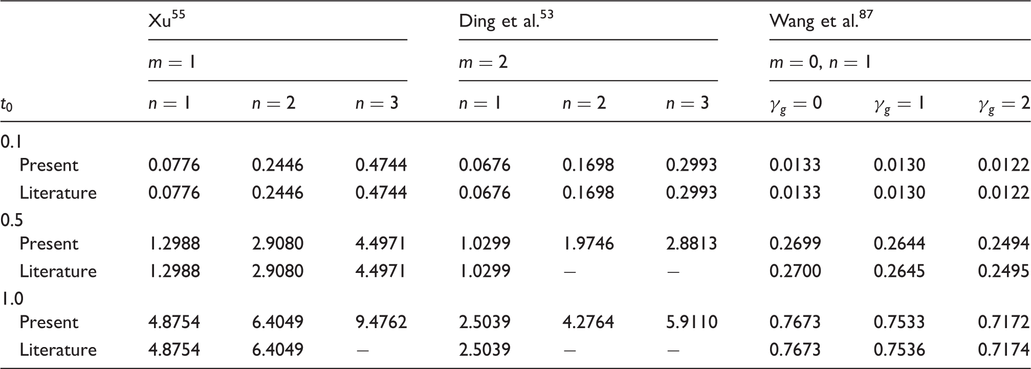
As a further check, Figure 4(b) displays the standardized active and reactive radiated (modal) sound powers, and for both axisymmetric and nonaxisymmetric structural modes of the simply supported circular piezo-laminated plate, as calculated from equations (32), where excellent agreements are obtained with the axisymmetric results presented in Figures 2 and 3 by Rdzanek et al.85 (note that the numerical results presented in Rdzanek et al. 85 are for axisymmetric loading, and based on certain asymptotic approximations). Next, we let the z-dimensions of the piezo-actuator/sensor laminae in our general code nearly zero and calculated selected modal radiation efficiencies of the circular panel based on the following relationship 37 (see equation (29)). Good agreements are obtained with the results provided in Figure 1 by Zawieska et al.86 as shown in Figure 4(c) (note that the numerical data in Zawieska et al.86 are for axisymmetric loading, and based on the low-frequency assumption). Subsequently, Figure 4(d) presents the normalized radiation pattern plots of the simply supported circular piezo-laminated plate for the (1,0) axisymmetric and the (1,1) nonaxisymmetric modes (see equations (17)) at both long and short wavelengths Excellent agreements are obtained with the results presented in Figure 2 by Christiansen et al.57 (note that the plots have been normalized with respect to their peak values). Here, it should be noted that at the low-frequency selection radiation patterns of the symmetric and asymmetric modes are very similar to those of a monopole and a dipole radiator, respectively. Also, it is noteworthy that, although the numerical results presented by Christiansen et al.57 include the nonaxisymmetric loading situation, they are based on the simplifying far-field approximation. Lastly, we used our main code to compare the calculated nondimensional natural frequencies (i.e. as read from the associated displacement spectra plots)24 with the exact results based on the 3D elasticity theory presented in Refs.53,55,87 for various axisymmetric and nonaxisymmetric vibration modes of simply supported thick laminated circular plates in the nonexistence of fluid coupling for designated thickness parameters The outcome, as displayed in Table 2, demonstrate very good accuracies.
Nondimensional natural frequencies for various simply supported thick circular plates without fluid loading.
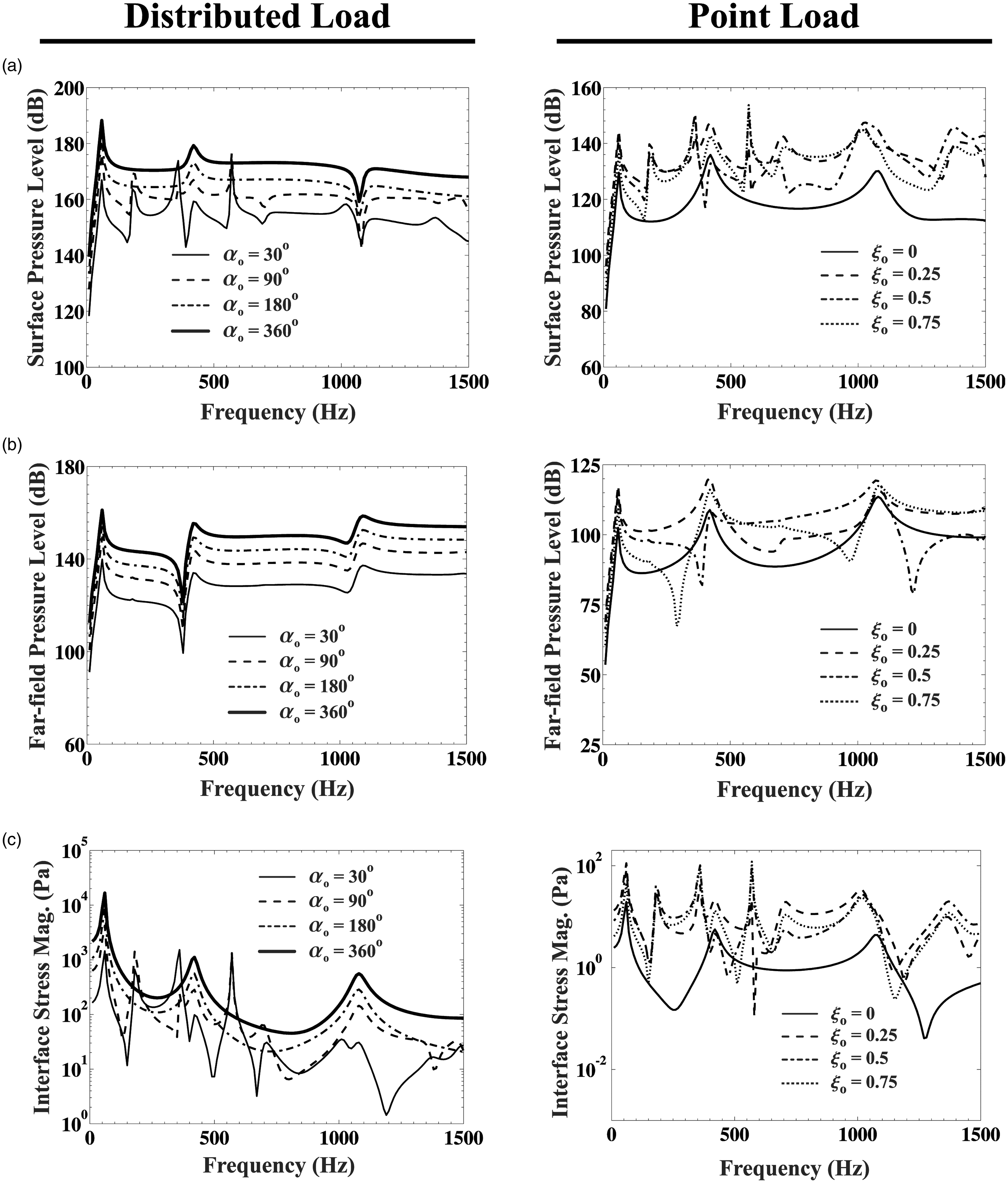
At this point, before considering the full active sound radiation control problem, it is worthy to briefly study some important sound radiation and mechanical characteristics of the water-immersed circular piezo-laminated /steel/PZT4 panel , . For a comprehensive study on the mechanical properties of the thick piezo-composite panel, the reader is referred to the literatures.53–55Figure 5 presents the frequency spectrums of off-axis radiated surface/far-field sound pressure levels, SPL (dB), at the observation points () as well as the normal stress magnitude at the interface between the piezoelectric sensor and the core layers, (Pa), in two basic (nonaxisymmetric) loading configurations. In the first loading case (i.e. the first column subplots), four separate transverse pie-shaped homogenous distributed mechanical loads N/m2; are considered, while in the second loading case (i.e. the second column subplots), unit amplitude point loads at four different positions along the panel radius N; are applied. The most interesting observations are as follows. As the action area (wedge angle ) of the applied distributed surface load increases, the radiated surface/far-field pressure levels as well as the normal interface stress magnitudes notably rise, especially in the mid- to high-frequency range, which is as expected. In the second loading configuration, the smallest sound radiation and interface stress levels are observed when the circular panel is excited exactly at its centre point, which is clearly linked to excitation of only the axisymmetric modes. As the excitation position of the point load is changed away from the panel centre point, the nonaxisymmetric modes also get involved, ultimately leading to constructive/destructive interference effects, depending on the frequency of excitation. Moreover, simple comparisons of the Figure 5(a) and (b) subplots (i.e. the off-axis radiated surface/far-field sound pressure level spectrums) indeed demonstrate that, while the effects of the nonaxisymmetric structural modes are strong near the surface of the panel, they seem to nearly disappear in the far-field. Lastly, it is clear from the first subplot in Figure 5(c) that increasingly more nonaxisymmetric structural modes show up in the interface stress response curve, as the asymmetry of loading action area increases (e.g. for ).
(a) The off-axis radiated surface sound pressure level spectrums of a water-immersed circular piezo-laminated panel in two basic loading configurations. (b) The off-axis radiated far-field sound pressure level spectrums of a water-immersed circular piezo-laminated panel in two basic loading configurations. (c) The normal interface stress magnitude spectrums for a water-immersed circular piezo-laminated panel in two basic loading configurations.
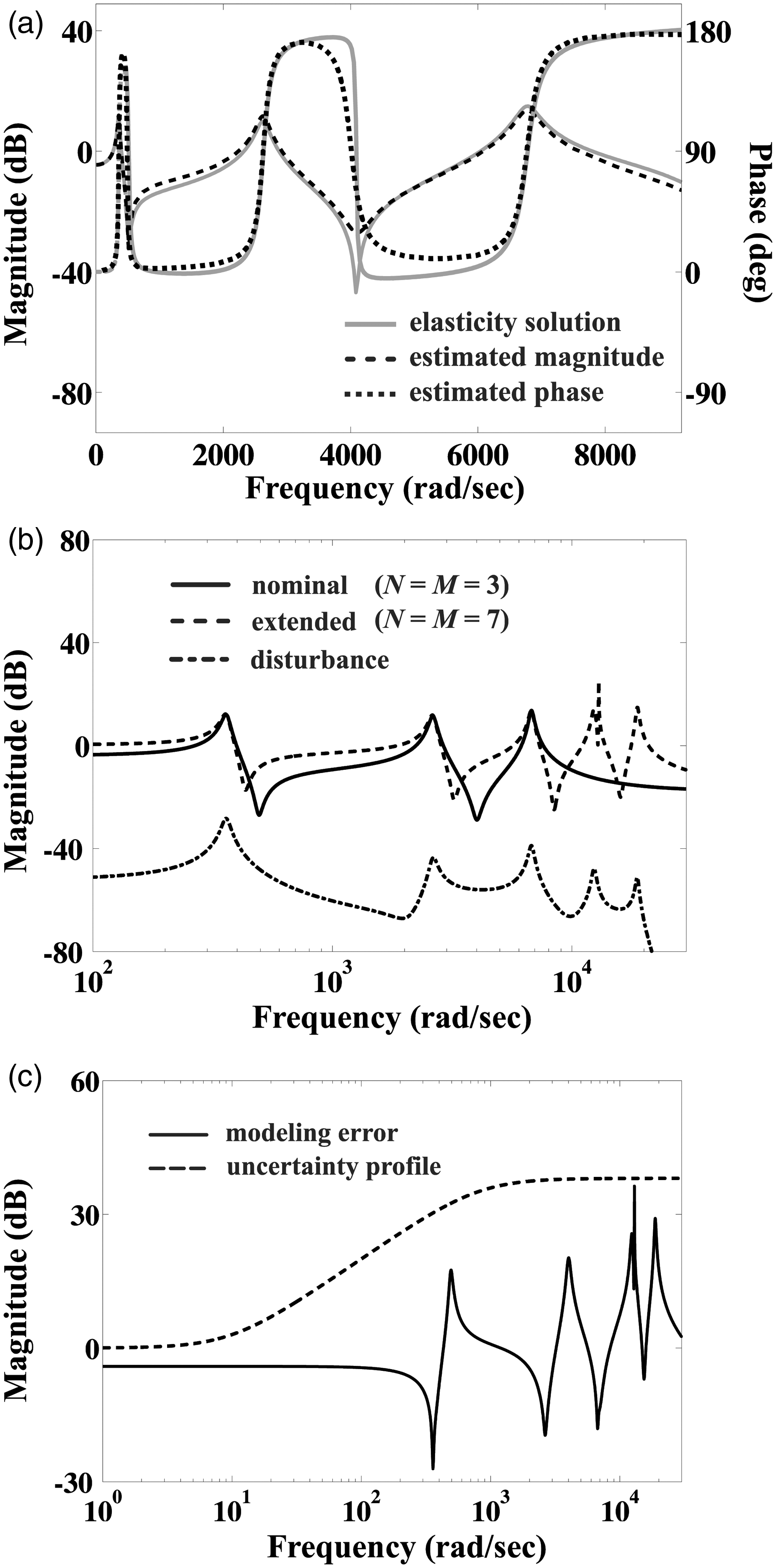
Now, as stated earlier, MATLAB System Identification Toolbox N4SID function is used here to identify the sixth-order state-space representation of the smart structure from the calculated input/output (actuator/sensor voltage) frequency response data. This estimated model is subsequently used as our nominal system, followed by application of MATLAB Robust Control Toolbox and Simulink® software for design and simulation of the control system. Figure 6(a) displays the magnitude and phase of the calculated normalized sensor output voltage for the nominal model with , and the sixth-order identified model for a harmonic actuator input voltage of 200 volts. Here, it should be noted that the output voltage normalization is done with respect to that of an extended model at with Obviously, the estimated model represents the dynamics of the system very well within the targeted frequency range . Figure 6(b) compares the normalized frequency response functions of the identified nominal model, , and the identified extended (14th order with ) model, . Also shown is the normalized frequency response function of the identified 14th-order model, (see Figure 2(b)), for an external mechanical disturbance of annular form, N, applied on the top surface of the piezo-laminated panel, where ‘H’ denotes the Heaviside function. Clearly, the nominal model), deviates from the extended model ) outside the targeted frequency range ). In other words, the identified nominal model is not suitable for frequencies higher than 9000 rad/s, and thus the modes outside this frequency band will be assumed as uncertainty of truncated system. Figure 6(c) displays the modelling error (i.e. the relative difference between the latter two models, or shown with the solid curve) in addition to the weighting function, = (designated by the dashed curve), which is designed to characterize an upper bound for the modelling error in the entire f6requency range and reduce the effects of the neglected high-frequency residual modes, to keep away from the spillover problems (see equation (52)).78
(a) The magnitude and phase of the calculated sensor output voltage for the real and identified models. (b) The frequency response functions of the identified nominal model, , the identified extended model, G, and the disturbance model, . (c) The modelling error and the upper bound weighting function .
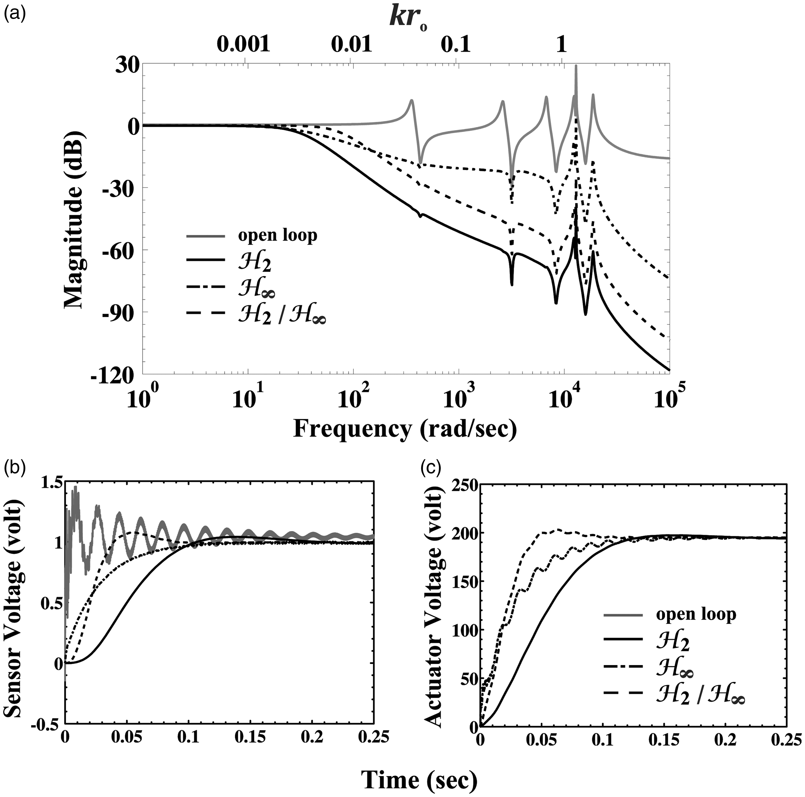
As noted previously, in order to reject the effect of the external disturbance, d, on the error signal, e (see Figure 2(b)), the magnitude of sensitivity function, , must be kept small in low-frequency range.76 This can be done by choosing a proper a low-pass filter in the form where , , sets requirements on the control performance (e.g. the bandwidth frequency and steady-state tracking error79). In addition, to restrict the control signal amplitudes and to avoid depolarization of the piezoelectric actuator (i.e. by exceeding the maximum 200 V regulation voltage limit), as well as reducing the possibility of residual mode excitation, a high-pass filter with , and , is used for weighting the function . After choosing the weighting functions, , as explained above, the generalized plant can be constructed and subsequently the controller can be synthesized using the adopted controller design procedure (see Figure 2(a)). Figure 7(a) compares the closed-loop frequency domain performance of our mixed-norm controller with that of a controller and a controller utilizing the above selected weighting functions. Here, for the mixed-norm controller, the robust stability constraint is set as in conjunction with an additional regional pole placement constraint selected as the open left half plane. This way, the synthesized controller is found to satisfy the mixed sensitivity norm . Also, the and controllers are, respectively, found to satisfy the following stacked sensitivity norms, Furthermore, all three controllers are found to be of ninth order. Here, it is clear from the figure that the first three response peaks in the open-loop (proper) system are effectively annihilated, while the remaining two peaks are greatly attenuated. Moreover, the bandwidth frequency associated with the mixed-norm controller is at least about 50% higher than that corresponding to either of the or controllers. Consequently, the mixed-norm controller is expected to display a faster time response. This fact is illustrated in Figure 7(b), where the extended system closed-loop responses to a step reference signal, for the adopted controllers are presented. It is clear that all three control systems promptly track the reference signal with less than 10% overshoot), and with the best performance being linked to the mixed-norm controller with Also shown are the corresponding actuator regulation voltages, , which all gradually converge towards the 200 volts asymptote. Here, it is clear from the last subplot that, owing to the relatively large thickness of the adopted PZT4 actuator layer ), the maximum applied actuator control voltages remain well below the associated saturation limit noted in the literatures.88,89
(a) Comparison of the frequency domain performance of the closed-loop systems. (b) Comparison of the closed-loop time domain responses to a step reference signal, and the associated applied regulation voltages.
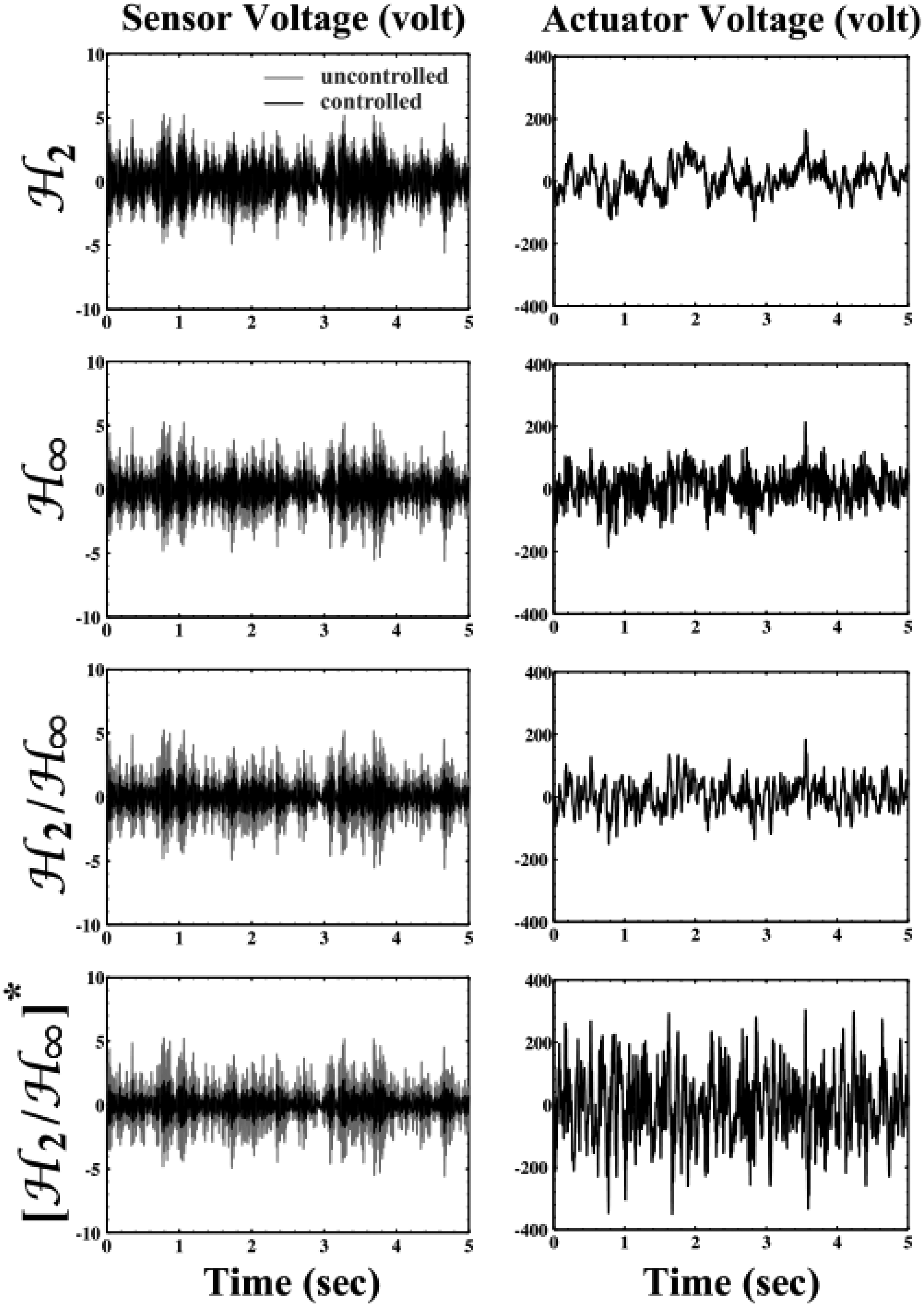
Figure 8 displays the disturbance rejection performance of the smart circular plate in the time domain for a broadband random (Gaussian white noise) mechanical disturbance applied over an annular region designated by on the top panel surface, while applying the mixed-norm , the , and the controllers to the identified extended model (see Figure 2(b)). The associated regulation voltages are shown in the second column of the figure. Also shown are results using a second mixed-norm strategy which excludes the regulated output channel associated with the performance (i.e. there is no restrictions on the actuator signal in the generalized plant), denoted in the figure by , with the robust stability constraint set as and the mixed sensitivity norm obtained as . The success of both mixed-norm robust active control strategies with a matched distributed actuator–sensor pair for proper rejection of the external random disturbance without causing any instabilities is clear. The time domain performance of the mixed-norm is slightly superior, however, at the expense of a higher actuator control effort.
The disturbance rejection performance of the smart panel in the time domain for a broadband random mechanical disturbance, along with the associated regulation voltages.
Conclusions
The 3D exact piezoelasticity theory and the multi-objective mixed control strategy are employed for robust active sound radiation reduction of an optionally thick, rigidly baffled, piezo-composite circular panel with constantly distributed matched sensor-actuator laminae, under broadband general (nonaxisymmetric) electromechanical excitations. In the first part of the numerical results, the important sound radiation and mechanical characteristics of the piezo-composite panel are briefly studied in two basic loading configurations. It is seen that, as the action area of the applied distributed load increases, the radiated sound pressure and interface normal stress levels notably increase, especially in the mid- to high-frequency range. Also, as the asymmetry of distributed loading is increased, increasingly more nonaxisymmetric structural modes appear in the radiated surface pressure and interface stress response spectrums. In the point loading configuration, the smallest effects are observed when the panel is excited exactly at its centre point, simply due to excitation of only the axisymmetric modes. As the excitation position is moved away from the panel centre point, the nonaxisymmetric modes also get involved, ultimately leading to observation of constructive/destructive interference effects, depending on the frequency of excitation. Moreover, it is seen in both (nonaxisymmetric) loading configurations that, while the sound radiation effects of nonaxisymmetric structural modes are very strong near surface of the panel, they markedly decline in (nearly disappear from) the far-field radiation spectrums. In the second part of the paper, system identification is conducted based on the low-frequency-coupled fluid–structure modes, and design/simulation of the control system is performed using reduced order (nominal) and extended models which are found to estimate the dynamics of the system very well within the targeted frequency range. An uncertainty profile (weighting) function sets an upper bound on the modelling error in the entire frequency range and reduces the effects of the neglected high-frequency residual modes in the closed-loop system. A low-pass filter is designed to reject the effect of the external disturbance on the error signal and set requirements on the control performance, while a high-pass filter is used to restrict the control signal amplitudes in order to avoid depolarization of the piezoelectric actuator as well as likelihood of residual mode excitation. It is found that the bandwidth frequency associated with the mixed-norm controller is at least about 50% larger than that of the or controllers. Also, the best tracking performance is observed for the closed-loop step response of the mixed-norm controller. Furthermore, the effectiveness of the adopted LMI-based multi-objective robust control strategy with a matched distributed actuator–sensor pair for proper rejection of the external disturbance (in the time domain), without causing any instabilities or actuator saturation problems, is demonstrated for the thick smart circular panel. Lastly, the main novelties/advantages of the proposed methodology may be summarized as follows:
Using the 3D linear piezoelasticity model in conjunction with the Rayleigh integral formula to develop an exact 3D analysis for the forced nonaxisymmetric fully coupled acousto-elastodynamic frequency response of a multi-layered piezo-composite circular plate of arbitrary thickness under heavy fluid loading, without applying any limiting (e.g. far-field, light fluid loading, and low-frequency) approximations, extendable for any arbitrary through-thickness variation of distributed material properties.
Applying an LMI-based multi-objective mixed-norm () robust control strategy for active low-frequency sound radiation control of the arbitrarily thick piezo-composite circular panel with satisfactory transient control performance and robust stability in the face of external disturbances and unmodelled dynamics (truncated modes).
Implementation of continuously distributed perfectly matched piezoelectric uniform force actuator and volume velocity sensor layers to effectively cancel the total volume velocity with the main contribution to the long wavelength acoustic power emission.
Footnotes
Declaration of conflicting interests
The author(s) declared no potential conflicts of interest with respect to the research, authorship, and/or publication of this article.
Funding
The author(s) received no financial support for the research, authorship, and/or publication of this article.
Appendix 1
References
1.
MagdenkovVA. The new type of constrained vibration-damping coating. J Low Freq Noise Vib Active Contr1996; 15: 107–113.
2.
HasheminejadSMKazemiradS. Dynamic viscoelastic effects on sound wave scattering by an eccentric compound circular cylinder. J Sound Vib2008; 318: 506–526.
3.
TokhiMOWoodR. Active noise control using multi-layered perceptron neural networks. J Low Freq Noise Vib Active Contr1997; 16: 109–144.
4.
KessissoglouNJPanJ. Active control of the structural and acoustic responses of a fluid-loaded plate; part I: analysis of the physical system. J Low Freq Noise Vib Active Contr1998; 17: 11–25.
5.
BozUAridoganUBasdoganI. A numerical and experimental study of optimal velocity feedback control for vibration suppression of a plate-like structure. J Low Freq Noise Vib Active Contr2015; 34: 343–359.
6.
WangBTBurdissoRAFullerCR. Optimal placement of piezoelectric actuators for active structural acoustic control. J Intell Mater Syst Struct1994; 5: 67–77.
7.
RosiGPaccapelliROllivierF. Optimization of piezoelectric patch positioning for passive sound radiation control of plates. J Vib Control2013; 19: 658–673.
8.
GardonioPElliottSJ. Smart panels for active structural acoustic control. Smart Mater Struct2004; 13: 1314–1336.
9.
BaumannWTHoFSRobertshawHH. Active structural acoustic control of broadband disturbances. J Acoust Soc Am1992; 92: 1998–2005.
10.
GharibMOmranAEl-BayoumiG. Optimal vibration control for structural-acoustic coupling system. J Vib Control2013; 19: 14–29.
11.
ChenKTChangSHChouCH. Active control by using optical sensors on the acoustic radiation from square plates. Appl Acoust2008; 69: 367–377.
12.
PohSBazABalachandranB. Experimental adaptive control of sound radiation from a panel into an acoustic cavity using active constrained layer damping. J Smart Mater Struct1996; 5: 649–659.
13.
VippermanJSClarkRL. Multivariable feedback active structural acoustic control using adaptive piezoelectric sensoriactuators. J Acoust Soc Am1999; 105: 219–225.
14.
CoxDEGibbsGPClarkRL. Experimental robust control of structural acoustic radiation. J Vib Acoust1999; 121: 433–439.
15.
SivriogluS. H∞ control for suppressing acoustic modes of a distributed structure using cluster sensing and actuation. J Vib Control2010; 16: 439–453.
16.
IorgaLBaruhHUrsuI. A review of H∞ robust control of piezoelectric smart structures. Appl Mech Rev2008; 61: 040802.
17.
ZhouKDoyleJCGloverK. Robust and optimal control, Upper Saddle River, NJ: Prentice Hall, 1996.
18.
SchererCGahinetPChilaliM. Multiobjective output-feedback control via LMI optimization. IEEE Trans Autom Contr1997; 42: 896–911.
19.
ClarkRCoxD. Active control design for acoustic radiation using mixed-norm optimization. J Acoust Soc Am2000; 108: 1345–1348.
20.
BoydSEl GhaouiLFeronE. Linear matrix inequalities in system and control theory, Philadelphia, PA: SIAM, 1994.
21.
ChilaliMGahinetP. H∞ design with pole placement constraints: an LMI approach. IEEE Trans Autom Contr1996; 41: 358–367.
22.
JungerMCFeitD. Sound, structures, and their interactions, New York: MIT Press, 1985.
23.
FahyFGardonioP. Sound and structural vibration: radiation, transmission and response, London: Academic Press, 2007.
24.
HasheminejadSMKeshavarzpourH. Active sound radiation control of a thick piezolaminated smart rectangular plate. J Sound Vib2013; 332: 4798–4816.
25.
FullerCR. Active control of sound transmission/radiation from elastic plates by vibration inputs I: analysis. J Sound Vib1990; 136: 1–15.
26.
MetcalfVLFullerCRSilcoxRJ. Active control of sound transmission/radiation from elastic plates by vibration inputs, II: experiments. J Sound Vib1992; 153: 387–402.
27.
DimitriadisEKFullerCR. Active control of sound transmission through elastic plates using piezoelectric actuators. Am Inst Aeronaut Astronaut J1991; 29: 1771–1777.
28.
Van NiekerkJLTongueBHPackardAK. Active control of a circular plate to reduce transient noise transmission. J Sound Vib1995; 183: 643–662.
29.
LeniowskaLLeniowskiR. Active attenuation of sound radiation from circular fluid-loaded plate. J Acoust Vib2001; 6: 35–41.
30.
RdzanekWZawieskaW. The total sound power radiated by a clamped-guided annular plate excited for vibrations by an external surface pressure. Arch Acoust2004; 29: 235–242.
31.
LeniowskaL. Modelling and control of structure-acoustic interaction problems via piezoceramic actuators. Mechanics2005; 24: 113–119.
32.
LeniowskaL. Effect of active vibration control of a circular plate on sound radiation. Arch Acoust2006; 31: 77–87.
33.
LeniowskaL. Influence of damping and fluid loading on the plate vibration control. Arch Acoust2008; 33: 531–540.
34.
WiciakJ. Modelling of vibration and noise control of a submerged circular plate. Arch Acoust2007; 32: 265–270.
35.
WiciakJ. Active control of a submerged circular plate. Hydroacoustics2008; 11: 441–448.
36.
JohnsonWRAslaniPSommerfeldtSD. Acoustic radiation mode shapes for control of plates and shells. Proc Meet Acoust2013; 19: 065036.
37.
ElliottSJJohnsonME. Radiation modes and the active control of sound power. J Acoust Soc Am1993; 94: 2194–2204.
38.
JohnsonMElliottSJ. Active control of sound radiation using volume velocity cancellation. J Acoust Soc Am1995; 98: 2174–2186.
39.
ArenasJP. Numerical computation of the sound radiation from a planar baffled vibrating surface. J Comput Acoust2008; 16: 321–341.
40.
GardonioPLeeYSElliottSJ. Analysis and measurement of a matched volume velocity sensor and uniform force actuator for active structural acoustic control. J Acoust Soc Am2001; 110: 3025–3031.
41.
Kim ES. Acoustic MEMS transducers for biomedical applications. In: IEEE international frequency control symposium 2010, Newport Beach, CA, 1–4 June, pp.71–76. Los Angeles, CA: IEEE.
42.
HalimDChengLSuZ. Virtual sensors for active noise control in acoustic-structural coupled enclosures using structural sensing: robust virtual sensor design. J Acoust Soc Am2011; 129: 1390–1399.
43.
HorowitzSBSheplakMCattafestaLNIII. A MEMS acoustic energy harvester. J Micromech Microeng2006; 16: S174.
44.
ZhouQLauS. Piezoelectric films for high frequency ultrasonic transducers in biomedical applications. Progr Mater Sci2011; 56: 139–174.
45.
HasheminejadSMMehdizadehS. Acoustic performance of a multi-layer close-fitting hemispherical enclosure. Noise Contr Eng J2006; 54: 86–100.
46.
HasheminejadSMKazemiradS. Scattering and absorption of sound by a compound cylindrical porous absorber with an eccentric core. Acta Acust Acust2008; 94: 79–90.
47.
TzouHSFuHQ. A study of segmentation of distributed piezoelectric sensors and actuators, part II: parametric study and active vibration controls. J Sound Vib1994; 172: 261–275.
48.
DubeGPDumirPCKumarCB. Segmented sensors and actuators for thick plates and shells part I: analysis using FSDT. J Sound Vib1999; 226: 739–753.
49.
JulaiSTokhiM. Active vibration control of flexible plate structures with distributed disturbances. J Low Freq Noise Vib Active Contr2012; 31: 123–150.
50.
LucifrediLNagemRJLucifrediF. Elasto-acoustic response of a rib-stiffened multi-layer Hull system. J Acoust Soc Am2012; 132: 2040.
51.
StammbergerMVossH. Variational characterization of eigen values of a non-symmetric eigenvalue problem governing elastoacoustic vibrations. Appl Math2014; 59: 1–13.
52.
DingHJXuRQ. Exact solutions for free vibrations of transversely isotropic circular plates. Acta Mech Sol Sin2000; 13: 105–111.
53.
DingHJXuRQChenW. Exact solutions for free vibrations of transversely isotropic piezoelectric circular plates. Acta Mech Sol Sin2000; 16: 141–147.
54.
BianZLimCChenW. On functionally graded beams with integrated surface piezoelectric layers. Compos Struct2006; 72: 339–351.
55.
XuRQ. Three-dimensional exact solutions for the free vibration of laminated transversely isotropic circular, annular and sectorial plates with unusual boundary conditions. Arch Appl Mech2008; 78: 543–558.
56.
Kirkup SM. Fortran codes for computing the acoustic field surrounding a vibrating plate by the Rayleigh integral method. In: Mathematical methods, computational techniques, non-linear systems, intelligent systems, 2008, pp.26–28. Corfu: WSEAS Press.
57.
ChristiansenTLHansenOThomsenEV. Modal radiation patterns of baffled circular plates and membranes. J Acoust Soc Am2014; 135: 2523–2533.
58.
LiSHuangQ. An improved form of the hypersingular boundary integral equation for exterior acoustic problems. Eng Anal Bound Elem2010; 34: 189–195.
59.
AartsRMJanssenAJ. Sound radiation quantities arising from a resilient circular radiator. J Acoust Soc Am2009; 126: 1776–1787.
60.
JensenFBKupermanWAPorterMB. Computational ocean acoustics, 2nd ed. New York: Springer New York, 2011.
61.
Warson TG. Investigation of the boundary conditions applicable to underwater, air-backed flexible-diaphragm transducers 1968; accession number: AD0838790. Monterey, CA: Defense Technical Information Center.
62.
MellowT. On the sound field of a resilient disk in free space. J Acoust Soc Am2008; 123: 1880–1891.
63.
ConwayJTCohlHS. Exact Fourier expansion in cylindrical coordinates for the three-dimensional Helmholtz Green function. Zeitschrift für angewandte Mathematik und Physik2010; 61: 425–443.
64.
AbramowitzMStegunIA. Handbook of mathematical functions, New York: Dover, 1972.
65.
RdzanekWPRdzanekWJEngelZ. Theoretical analysis of sound radiation of an elastically supported circular plate. J Sound Vib2003; 265: 155–174.
66.
GeraldCFWheatleyPO. Applied numerical analysis, 7th ed. New York: Pearson, 2003.
MaoQPietrzkoS. Control of noise and structural vibration, London: Springer, 2013.
69.
GibbsGClarkRCoxD. Radiation modal expansion: application to active structural acoustic control. J Acoust Soc Am2000; 107: 332–339.
70.
LeeJCChenJC. Active control of sound radiation from rectangular plates using multiple piezoelectric actuators. Appl Acoust1999; 57: 327–343.
71.
SahuKCTuhkuriJ. Active control of sound transmission through soft-cored sandwich panels using volume velocity cancellation. Proc Meet Acoust2014; 20: 040004.
72.
ChandrashekharaKTennetiR. Thermally induced vibration suppression of laminated plates with piezoelectric sensors and actuators. Smart Mater Struct1995; 4: 281–290.
73.
PreumontA. Vibration control of active structures: an introduction, 3rd ed. Berlin: Springer-Verlag, 2011.
74.
Van OverscheePDe MoorB. Subspace identification for linear systems: theory, implementation, applications, Dordrecht: Kluwer Academic Publishers, 1996.
75.
LjungL. System identification toolbox user’s guide: for use with MATLAB, Natick, MA: The MathWorks Inc., 2001.
76.
SkogestadSPostlethwaiteI. Multivariable feedback control: analysis and design, Ne York: Wiley-Interscience, 2005.
77.
KytkaPEhmannCNordmannR. Active vibration µ-synthesis-control of a hydrostatically supported flexible beam. J Mech Sci Technol2007; 21: 924–929.
78.
KarINMiyakuraTSetoK. Bending and torsional vibration control of a flexible plate structure using H∞-based robust control law. IEEE Trans Contr Syst Technol2000; 8: 545–553.
79.
You W, Chen H and He X. Tracking control research of high-order flexible structures on the H-infinity control method. In: 2nd international conference on advanced computer control 2010, Vol. 5, Shenyang, China, 27–29 March 2010, pp.111–115. New York: IEEE.
80.
BaiMRZeungP. Design of a broadband active silencer using μ-synthesis. J Sound Vib2004; 269: 113–133.
81.
RafaelyBElliottSJ. H2/H∞ active control of sound in a headrest: design and implementation. IEEE Trans Contr Syst Technol1999; 7: 79–84.
82.
YangJS. Robust mixed H2/H∞ active control for offshore steel jacket platform. Nonlinear Dyn2014; 78: 1503–1514.
83.
CaraccioloaRRichiedeiaDTrevisanibA. Robust mixed-norm position and vibration control of flexible link mechanisms. Mechatronics2005; 15: 767–791.
RdzanekWJRdzanekWPEngelZ. Asymptotic formulae for the acoustic power output of a simply-supported circular plate. Acta Acust Acust2001; 87: 206–214.
86.
ZawieskaWMRdzanekWPRdzanekWJ. Low frequency estimation for the sound radiation efficiency of some simply supported flat plates. Acta Acust Acust2007; 93: 353–363.
87.
WangYXuRDingH. Free axisymmetric vibration of FGM circular plates. Appl Math Mech2009; 30: 1077–1082.
88.
Morgan Matroc Incorporated. Guide to modern piezoelectric ceramics, Bedford, OH: Electro Ceramics Division, 1993.
89.
BruchJJCSlossJMAdaliS. Optimal piezo-actuator locations/lengths and applied voltage for shape control of beams. Smart Mater Struct2000; 9: 205–211.