
Abstract
Ear surgery was performed using daylight illumination and the naked eye through much of the 1800s. While simple microscopes, basically inverting telescopes, were known from Galileo’s time, few physicians took advantage of these primitive magnifying devices. The quality of lenses improved greatly in the later part of the 19th century with advances in glass technology and factories devoted to shaping high-quality optics. 1 Ophthalmologists employed single lens loupes to allow crude, but effective intraocular surgery. 2 These loupes commonly consisted of convex lens attached to the surgeon’s own prescription glasses. Simple loupes suffered from limitations in magnifying power and operating distance. In response, telescopic systems combining several lenses and prisms were devised.
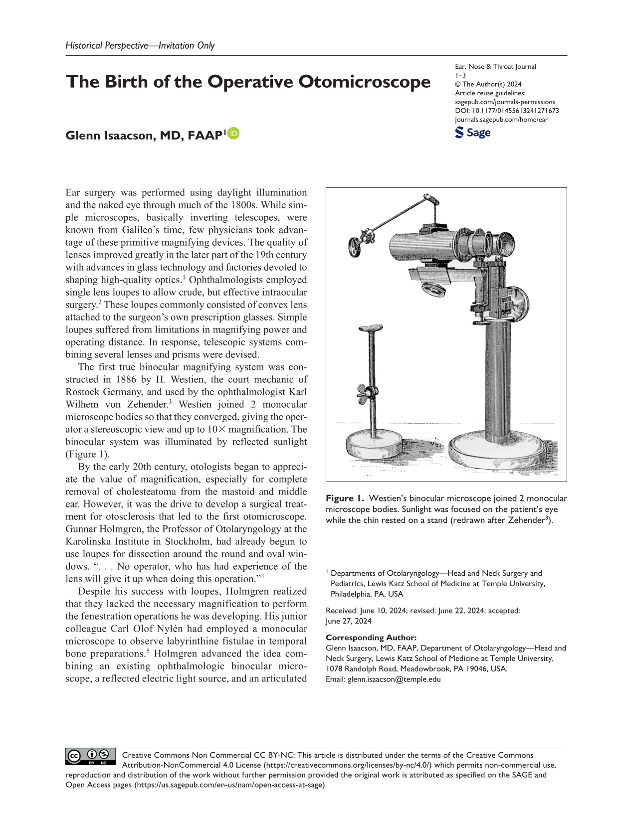
The first true binocular magnifying system was constructed in 1886 by H. Westien, the court mechanic of Rostock Germany, and used by the ophthalmologist Karl Wilhem von Zehender. 3 Westien joined 2 monocular microscope bodies so that they converged, giving the operator a stereoscopic view and up to 10× magnification. The binocular system was illuminated by reflected sunlight (Figure 1).
Westien’s binocular microscope joined 2 monocular microscope bodies. Sunlight was focused on the patient’s eye while the chin rested on a stand (redrawn after Zehender 3 ).
By the early 20th century, otologists began to appreciate the value of magnification, especially for complete removal of cholesteatoma from the mastoid and middle ear. However, it was the drive to develop a surgical treatment for otosclerosis that led to the first otomicroscope. Gunnar Holmgren, the Professor of Otolaryngology at the Karolinska Institute in Stockholm, had already begun to use loupes for dissection around the round and oval windows. “. . . No operator, who has had experience of the lens will give it up when doing this operation.” 4
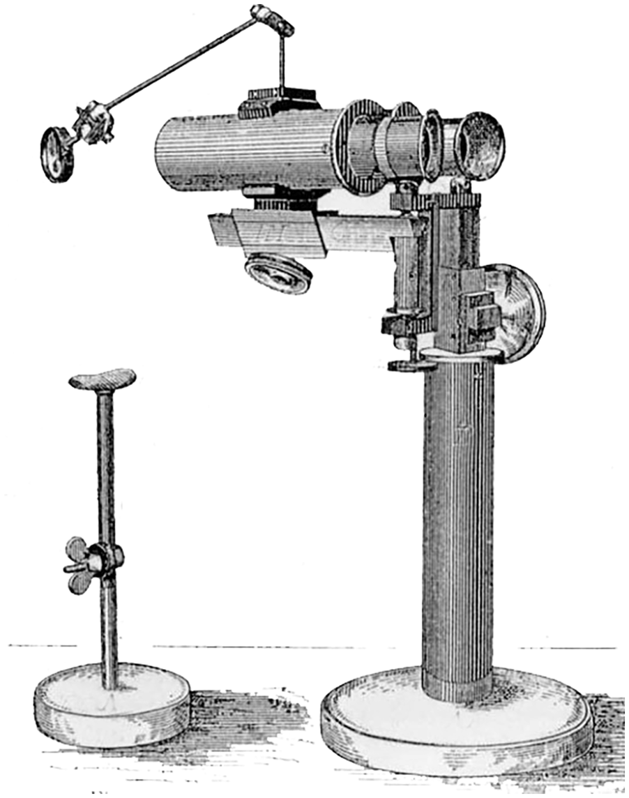
Despite his success with loupes, Holmgren realized that they lacked the necessary magnification to perform the fenestration operations he was developing. His junior colleague Carl Olof Nylén had employed a monocular microscope to observe labyrinthine fistulae in temporal bone preparations. 5 Holmgren advanced the idea combining an existing ophthalmologic binocular microscope, a reflected electric light source, and an articulated suspension (Figure 2). There were a number of deficiencies in this primitive system. The microscope’s suspension was awkward and the illumination was dim. The optics had a limited depth-of-field and the whole device had to be sprayed with formalin vapor to approximate antisepsis. Still, using the binocular microscope’s improved image detail, Holmgren successfully drilled openings in the promontory, and in the lateral and superior semicircular canals. His fenestration operations produced only temporary improvements in hearing, but the concept of the operative otomicroscope was born.
Holmgren combined an existing Carl Zeiss ophthalmologic binocular microscope, a mirror (M) and electric light source (L). An articulated suspension was attached to the operating table (from Holmgren 4 ).
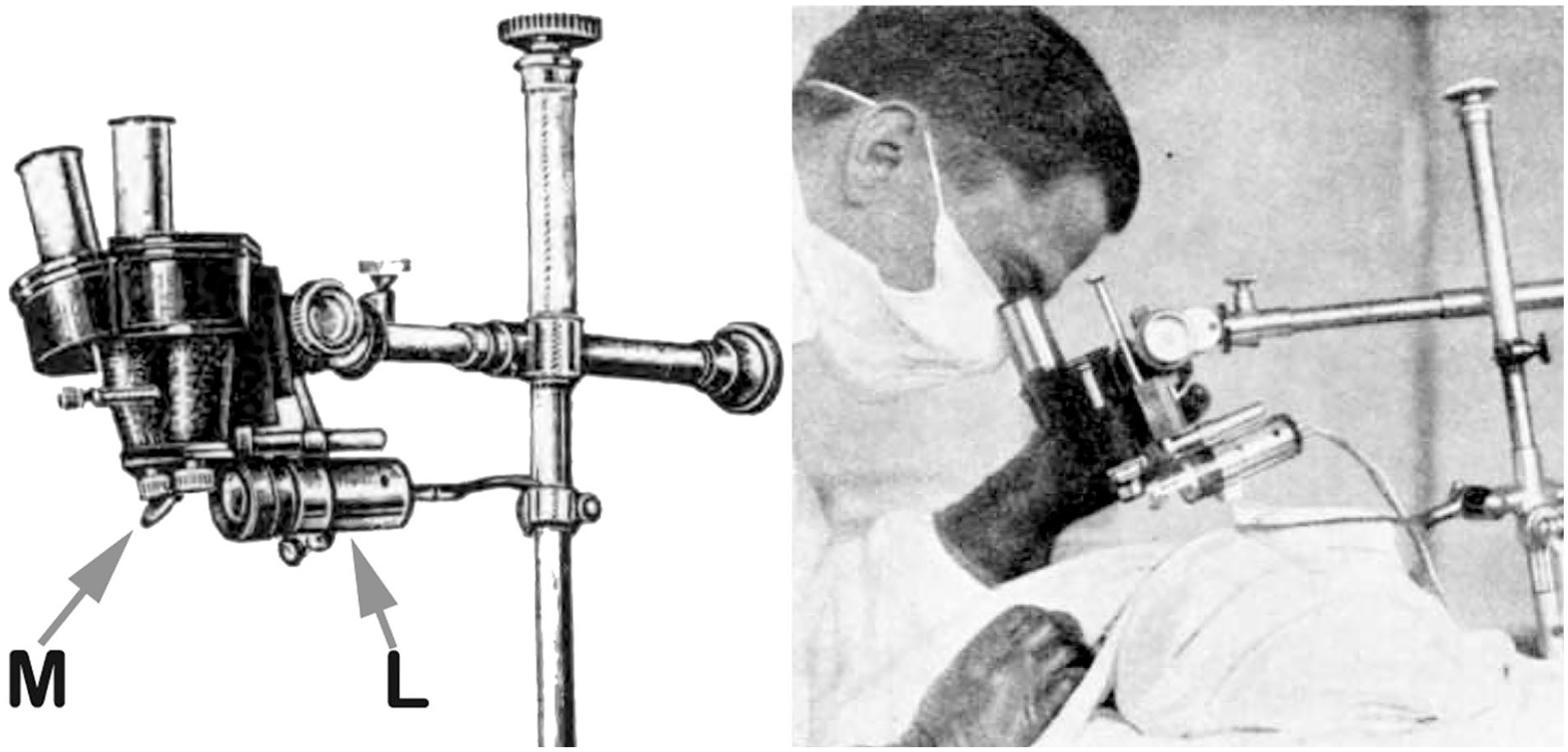
The early binocular microscopes were not widely accepted and most otologists continued using loupes and a headlight for middle ear work. This all changed in 1952 when Carl Zeiss, Oberkochen released the Zeiss-Opton microscope designed by Hans Littman 6 (Figure 3). The microscope head contained a series of double Galilean magnifiers that rotated into the optical tract and permitted rapid changes in magnification without refocusing. The following year, Littman modified the Zeiss-Opton collaborating with the otologist Horst Wullstein and the Operationsmikroskop-1 (OPMI-1) was born. The OPMI-1 used the Opton’s magnifying system but moved the hot incandescent bulb away from the operator and focused the light though the same objective lens as the observer optics, creating near-coaxial lighting (Figures 4 and 5). Equally important was the revolutionary floor stand. It consisted of a lead-weighted base on wheels; a tall smooth supporting column; a ring carriage attachment; and articulated arms with friction brakes on each articulation. This provided a steady base and permitted adjustment of the position and angle of the microscope head. A counterweight, located inside the floor stand column, allowed easy height adjustment during surgery. 7
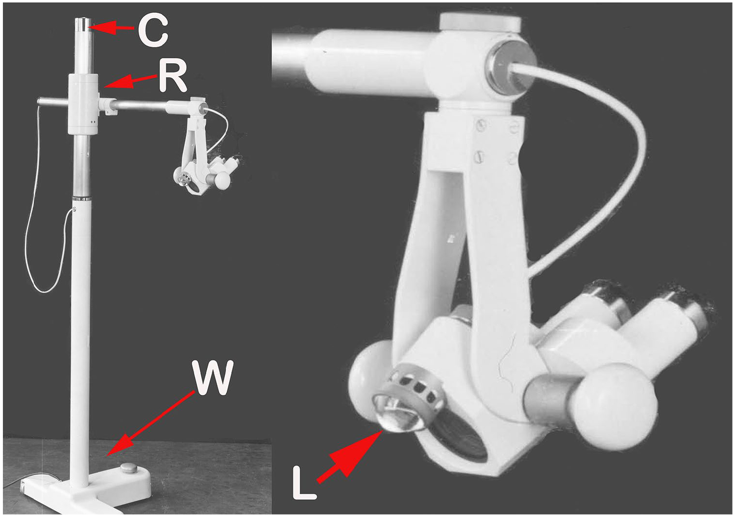
Zeiss-Opton. C, counterweight/pulley system; R, ring carriage; W, weighted base on wheels; L, direct illumination from incandescent bulb (by permission, Zeiss Archive).
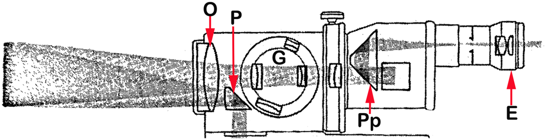
The OPMI-1 light path. Light from an incandescent bulb was directed by a prism (P) through the main objective lens (O). Reflected light from the subject passed through the objective, one of a series of rotating paired magnifiers (G) and was flipped by a porro prism (Pp) before arriving at the eyepiece (E) correctly oriented (redrawn after Littman 6 ). OPMI-1, Operationsmikroskop-1.
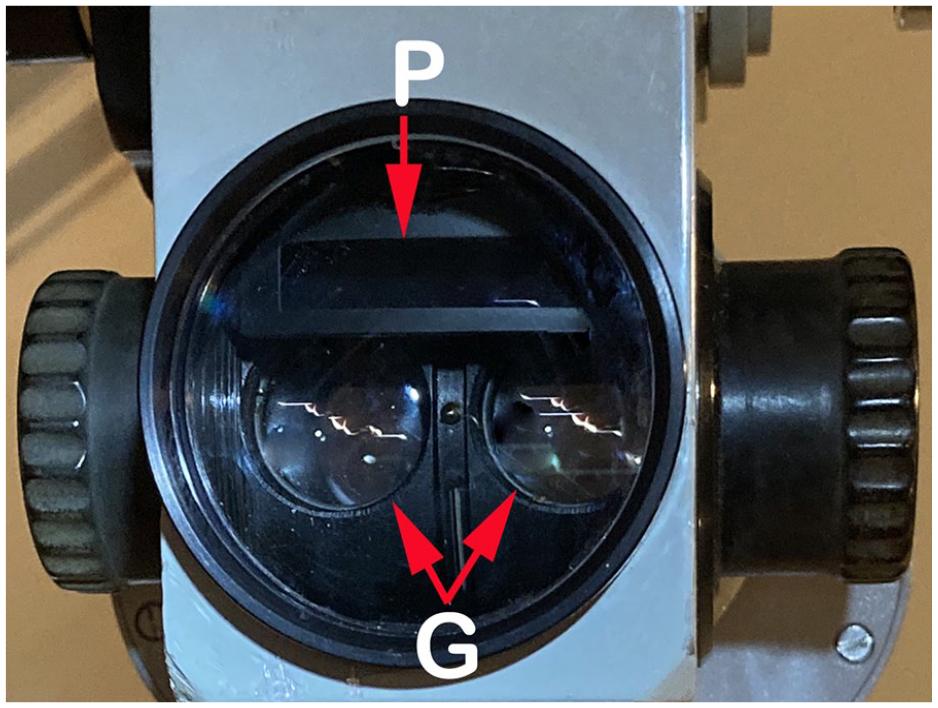
The OPMI-1 objective lens could be unscrewed and replaced to adjust operative focal length. The double Galilean magnifiers (G) and light source prism (P) are nearly coaxial. OPMI-1, Operationsmikroskop-1.
Within a few years, 2000 OPMI-1 microscopes were in use by otologists. 8 It was the 1950s and the stage was set for stapes mobilization, stapedectomy, tympanoplasty, and ossiculoplasty, each made possible by the operative otomicroscope.
Footnotes
Declaration of Conflicting Interests
The author declared no potential conflicts of interest with respect to the research, authorship, and/or publication of this article.
Funding
The author received no financial support for the research, authorship, and/or publication of this article.
Level of Evidence
5—expert opinion.