
Abstract
Direct steam generation (DSG) in linear parabolic collectors represents an effective pathway to improve solar-thermal energy utilization by eliminating the constraints of conventional heat-transfer fluids and enabling higher operating temperatures. This study develops a comprehensive energy and exergy modeling framework for a DSG solar collector receiver, integrating optical–thermal characteristics with detailed representations of radiative, convective, and conductive heat-loss mechanisms. The receiver performance is investigated under varying solar irradiance levels and mass flow rates, and the axial thermal behavior is resolved into three distinct regions corresponding to single-phase heating up to saturation, two-phase evaporation, and superheated steam heating. The numerical approach is validated through a grid-independence study, demonstrating solution stability beyond 1000 elements, and through consistency checks with published correlations for temperature evolution and two-phase pressure-drop behavior. The results indicate that, at a solar irradiance of 1000 W m−2 and an optical quality of 0.8, the receiver achieves a thermal efficiency of 92.17%. Exergy analysis reveals an overall receiver exergy efficiency in the range of 35–38% at 900 W m−2, assuming a reference temperature of 298 K, underscoring the impact of irreversibilities associated with finite-temperature heat transfer and environmental losses. The distribution of exergy destruction shows that radiative and ambient losses account for 44.9%, followed by conduction (31.8%) and convection (23.3%). These findings provide practical guidance for receiver design improvements and operational strategies aimed at more effective solar energy exploitation.
Introduction
Concentrated solar thermal (CST) power plants represent a promising pathway for large-scale renewable electricity generation. Among CST technologies, linear parabolic collectors (LPCs) have gained particular attention due to their economic advantages and technological maturity (Jahangiri et al., 2021; Wang et al., 2022a). Most LPC systems operate at temperatures around 400°C, utilizing hot oil as the heat transfer fluid (HTF) (Huang et al., 2021; Yu et al., 2023; Zhu et al., 2017). A substantial portion of previous research on LPCs has examined the Luz Company collectors employed in the Solar Electric Generating Systems (SEGS) located in Southern California (Li et al., 2023a; Wu et al., 2022). Although SEGS features a well-established design, its reliance on hot oil presents several drawbacks. Specifically, the use of thermal oil requires a heat exchanger to produce steam for power generation (Li et al., 2023b; Tian et al., 2023), and the oil must be periodically replaced due to thermal degradation, leading to increased operational costs (Yang et al., 2023a; Zheng et al., 2023).
While alternative receiver concepts—such as wick-assisted heat pipe collectors—have been explored for their passive thermal regulation and decoupled heat transfer mechanisms (Brahim and Jemni, 2012; Taoufik et al., 2013), direct steam generation (DSG) in parabolic trough systems remains the most promising option for high-temperature and utility-scale applications. DSG offers notable advantages, including simplified piping, elimination of intermediate heat exchangers, and the ability to achieve higher steam qualities under concentrated solar flux.
These limitations of hot oil have motivated the Luz Company, original developers of the SEGS system, to investigate DSG technology (Liu et al., 2023a, 2023b). In DSG systems, steam is produced directly within the absorber tube, removing the need for an intermediate HTF (Chen et al., 2023; Zhu et al., 2023). Compared with SEGS, DSG reduces fire and environmental risks associated with thermal oils, eliminates the need for strict oil-temperature control to avoid decomposition, decreases operational costs by removing oil replacement requirements, and reduces the frequency of defrosting procedures (Kuang et al., 2018; Yang et al., 2023b).
Three principal operating modes have been developed for DSG systems. In the circulating mode, water is heated and partially evaporated in one section and then superheated in a separate section (Cohen and Kearney, 1994; Lin et al., 2023; Wang et al., 2023, 2024). In the once-through mode, preheating, evaporation, and superheating occur sequentially in a single pass without phase separation (AlMallahi et al., 2022; Eck and Steinmann, 2002). The multistage water-addition mode injects water at multiple points along the absorber tube, also following a once-through sequence but with distributed water addition (Alwan et al., 2022; Saberi Shahmarvandi et al., 2022).
Although the once-through mode offers significant cost and design advantages, it introduces substantial challenges in predicting and controlling two-phase flow behavior inside the absorber tubes. To address this, several studies have examined the thermo-hydraulic characteristics of once-through DSG systems. Feldhoff et al. (2012) developed both a discrete finite-element model and a moving-boundary model to analyze system behavior. The moving-boundary model predicts fundamental system states using limited input data, while the discretized finite-element model relies on localized heat-transfer coefficients that assume a constant two-phase behavior.
Additional research efforts have addressed related aspects of solar thermal systems. Wang et al. (2019) proposed a novel concentrating photovoltaic/thermal (CPV/T) system based on a compact linear Fresnel reflector. Tiwari et al. (2020) performed a thermodynamic analysis of an Organic Rankine Cycle driven by a reversed-absorber hybrid PV/T compound parabolic concentrator. Wang et al. also examined a CPV/T system employing a spectral beam splitter. Knysh (2020) conducted thermo-fluid modeling of low-temperature parabolic trough systems using multiwalled carbon-nanotube/water nanofluids. Stanek et al. (2022) investigated the effect of solar-tracker errors on parabolic trough performance through optical and thermodynamic analysis. Several studies have explored the impact of nanofluids on CST systems (Aryanfar et al., 2022; Huang and Marefati, 2020; Natividade et al., 2019; Wang et al., 2022b), while others have examined the influence of enhanced heat transfer on LPC performance (Alayi et al., 2021; Bie et al., 2020). Fochang et al. evaluated corrugated absorber tubes and reported an 8.4% increase in the effective heat-transfer coefficient and a 13.1% reduction in maximum thermal strain. Li et al. (2019) analyzed direct steam production and observed that increasing solar irradiance expands the superheating region while reducing the preheating zone. Feng et al. (2019) proposed the use of a flash tank to mitigate two-phase instabilities in DSG systems, and Iodice et al. (2018) developed a mathematical model to optimize ambient conditions for improved DSG efficiency.
Considerable progress has been made in understanding boiling-related phenomena in solar absorbers. High-speed visualization has shown that boiling exhibits distinct regimes, each characterized by different heat-transfer mechanisms. Film boiling is of particular relevance in DSG systems, especially because of its relationship to the critical heat flux (CHF). CHF defines the maximum heat flux beyond which a sudden increase in wall temperature occurs due to surface dryout, imposing constraints on the safe operating range of solar receivers. This limit depends strongly on system design and the imposed heating profile (Ahn et al., 2010; Das et al., 2003).
Despite extensive research on DSG receivers, existing models often rely on simplified or quasi-steady assumptions and do not fully capture the spatial evolution of phase change under variable heat-flux conditions. To address this gap, the present study develops an enhanced homogeneous two-phase model that incorporates variable thermophysical properties, couples the solar heat-flux distribution with fluid dynamics, and employs a Look-Up-Table (LUT)-based method to accurately predict the CHF. This framework enables a more realistic evaluation of boiling behavior, heat transfer, and steam production within the absorber. Building on this modeling capability, the study also evaluates thermal-stress limitations to support the design and optimization of high-performance DSG receivers. The remainder of the article presents the proposed model, its validation, and a detailed analysis of the absorber's thermohydraulic and structural performance.
Materials and methods
Governing equations
This study employs water as the HTF, and the governing energy equations for the linear parabolic concentrator are derived from a thermodynamic standpoint.
Thermal model
Figure 1 illustrates the thermal-resistance network across the cross-section of a parabolic solar collector. During sunny conditions, incident solar radiation is reflected by the parabolic mirrors and concentrated onto the heat-collecting element. A portion of this concentrated energy is absorbed by the glass envelope

(a) Schematic view of the linear parabolic trough equipped with a metallic reflector that concentrates incident solar radiation onto the focal line. (b) Cross-section of the receiver illustrating the absorber tube with selective coating, the heat-transfer-fluid region, the vacuum annulus, the glass envelope, the end-cap and getter components, and the dominant heat-transfer pathways.
Part of the absorbed energy is transferred to the HTF through forced convection
The energy absorbed by the glass—via both convection and radiation—subsequently passes through the glass layer and is lost to the surroundings through external convection
For modeling, the heat transfer relations for each component of the linear parabolic concentrator system have been used, and the energy equation of the studied system can be seen in equation (1).

The finite volume method is used to discretize the domains and use the steady state energy in each control volume (CV) in steady state conditions. Considering two optional CVs, the heat balance can be written for the glass tube and wall.

The heat balance in the CV of the glass wall is in the form of the following relationship:

The convective flux from the tube to the fluid (a) will be established when the flow is of an internal flow type. The fluid in the internal flow is enclosed by the pipe wall. After the heat passes through the absorbent wall during conduction heat transfer, the heat is transferred to the fluid inside the tube. This transfer is of a displacement type and due to the confinement of the fluid by the pipe, the rules and fixed numbers related to the internal flow are used. Therefore, it can be written (Hachicha et al., 2013):


Conductive heat flux in the absorber (a) will be created when the heat energy to the absorber absorbs heat during radiant heat transfer and passes through the absorber wall through the conductive heat transfer process. In this case, it can be obtained through the following relationship (Natividade et al., 2019):

After the thermal energy reaches the glass through radiation, the heat passes through the glass wall during a conductive heat transfer, which for the tubular glass enclosure, the conductive heat flux in the glass

According to the principles of heat transfer, after reaching the absorber, according to its absorption coefficient, some amount of heat energy is absorbed by the tube, which passes through the wall and is transferred to the fluid by the conduction heat transfer mechanism. After absorbing this amount of heat, some amount is also reflected toward the glass according to the reflection coefficient of the absorber (tube) during two processes of displacement heat transfer of free and radiant type. In this case, the convective heat flux is transferred from the absorber to the glass

Also, the transfer heat flux from the glass to the absorber

In the above relationships, effective thermal conductivity and Rayleigh number will be obtained through the following relationships (Ghorbannejad et al., 2022; Hasanzadeh et al., 2021):


After two heat transfers from the absorber to the glass, the heat energy is transferred from the glass


The radiant heat flux from the absorber to the glass (a) will be expressed through the following equation (Hachicha et al., 2013):


The radiant heat transfer on the surface of the absorber

The radiation heat flux entering the glass

In equations (17) and (18),


Efficiency is usually interpreted as the ratio of energy that does useful work to the total energy received and is defined as follows for the current system (Hachicha et al., 2013):

Exergy analysis of the receiver section
The exergy analysis is restricted to the absorber region of the linear parabolic concentrator, where the heat is absorbed, transferred through the selective-coated wall, and delivered to the working fluid. The optical–thermal processes in this focal zone are characterized by large temperature gradients that cause notable exergy destruction. The analysis presented here evaluates these irreversibilities across the following domains: (i) solar irradiation, (ii) absorber metal wall, (iii) fluid–solid convection, and (iv) re-radiation to ambient.
Exergy of the incident solar radiation
The available exergy in solar radiation reaching the receiver surface is expressed by the Petela relation:

where Q˙solar = AcIηoptQ˙solar = Ac Iηopt, Ts = 5777 KTs = 5777 K is the sun temperature, and T0T0 is the ambient temperature (298 K).
Exergy transfer through the absorber wall
Assuming steady-state heat conduction through the metal tube wall:

The associated exergy flux is:

The exergy destruction due to conduction inside the absorber wall is obtained from:

Exergy transfer from wall to working fluid
Heat transfer to the fluid by forced convection inside the absorber tube is:

The corresponding exergy transferred to the fluid:

And the exergy destruction across the convective interface:

Exergy loss by re-radiation and convection to ambient
The total re-radiation and natural convection from the outer glass envelope to ambient air cause additional exergy loss:

Overall exergy efficiency of the receiver
The receiver exergy efficiency is defined as:

And the total exergy destruction ratio (to identify dominant losses) as:

With i = cond, conv, loss.
Single-phase flow model
The thermal model of water vapor inside the absorber tube can predict the heat transfer coefficient and pressure gradient. The pressure drop in pipes for single-phase flow can be calculated from the following equation:

In the above relationships, the friction coefficient is obtained through the following relationships for smooth and turbulent flow, respectively (Wang et al., 2022b):


Homogeneous two-phase flow model
If the fluid passing through the absorber is in a two-phase state, the pressure drop is obtained from the following equation:

In the above relationship, TP is the two-phase pressure drop and FO is the saturated liquid pressure drop or flow rate. Coefficient


Definition of problem and numerical solution method
The receiver model, which includes a set of heat receiver components, is shown in Figure 1, and in the previous section, the separation modes of the heat flux into the absorber tube are explained. The absorber chamber in this power plant is considered as two concentric tubes. The inner tube, which is absorbent, is made of steel, the outer tube is made of Pyrex, and the chamber is a glass tube concentric with the absorbent tube. In order to reduce heat loss, there is a relative vacuum between the two pipes. The one-time water mode is used for the DSG system. In the desired solar collector, the current is considered stable and the energy absorbed by the collector is proportional to the concentration of radiation. The intensity of incoming solar radiation is fixed
In this research, the surrounding environment is considered ideal. Also, the sky will be considered cloudless and clear, which is the environmental condition in most regions of Iran. Of course, the effect of changes in radiation intensity has been investigated. Slow wind conditions are assumed; because in real work conditions, in strong wind conditions, the system is usually turned off so as not to damage the system. By collecting weather data for a specific area in order to implement this system, a good estimate of the production power of this solar system can be obtained.
The discretization of the equations has been done by using the progressive Newton, which calculates the different parameters of the problem in each time interval and discretizes along the pipe and solves the problem. To solve the problem, several inner loops are used to determine the effect of parameter changes on the problem. Solving the problem by Newton's method makes its solution very simple and reduces the calculations for complex equations, and the accuracy of the problem can be increased by reducing the size of the temporal and spatial elements. But reducing the elements too much may cause calculation errors in computer problems. Figure 2 shows the overall flowchart of the algorithm. The production network is one-dimensional and the independence of the network has been investigated by dividing the spatial parameters over the length of the pipe. The results of grid independence show that when the number of elements reaches more than 1000, the results do not depend on the number of elements.

Flowchart of the general algorithm.
Grid independence study
To ensure that the numerical predictions are not influenced by the spatial discretization, a grid independence study was carried out. The computational domain of the absorber tube was discretized into several mesh configurations with progressively increasing numbers of nodes. For each grid, the model was solved under identical boundary and operating conditions, and key output variables—such as the outlet temperature, steam quality, and average heat flux—were compared. Grid convergence was assessed using the relative difference between successive mesh refinements, defined as:

where
The computational domain considered in this study consists of the absorber tube and the water/steam flow inside it. The corresponding numerical mesh is shown in Figure 3. The domain is discretized into a series of CVs along the flow direction in order to resolve the axial variation of pressure, temperature and phase quality. A sufficiently fine resolution is also adopted in the radial direction to capture the heat transfer between the absorber wall and the two-phase fluid. To ensure that the numerical results are independent of the grid resolution, several mesh configurations with different numbers of elements were tested under identical operating conditions, as summarized in Table 1. The selected mesh provides a good compromise between accuracy and computational cost.

Computational mesh of the absorber tube and heat transfer fluid (water/steam) used in the numerical simulations.
Grid independence analysis.

As shown in Table 2, the solution stabilizes as the number of elements increases. The variation in outlet temperature between Grid 4 and Grid 5 is less than 0.01%, indicating that further refinement yields no meaningful improvement in accuracy. Therefore, the mesh with 200 elements was selected for all subsequent simulations, as it provides an optimal balance between computational accuracy and execution time.
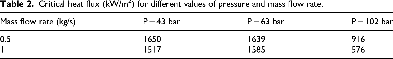
Critical heat flux (kW/m2) for different values of pressure and mass flow rate.
In this research, changes in water temperature and pressure along the length of the pipe are investigated for different parameters and conditions. In order to validate the results of these changes, two different studies have been used. The temperature changes validation is based on the work of Hachicha et al. (2013). For this purpose, all the parameters used in this research have been used. The only difference in this simulation is the use of an optical model. In Alwan et al., the simulation of the parabolic solar collector has been investigated as a single phase and the changes in the amount of radiation have been taken into account in a radial manner, but in the case of this research, the changes are an equation independent of the direction of radiation. It has been simplified. The results of the simulation of liquid and absorbent temperature changes along the length of the pipe for a pressure of 100 bar at an angle of 90° are shown in Figure 4. The results of the simulation show that the optical model used is in good agreement with the radial optical model stated in the research (Hachicha et al., 2013) for the 90° angle and the maximum difference of the results is close to 4.7% and the minimum is 1.5%.

Comparison of the results obtained for changes in liquid temperature and absorber temperature along the length of the pipe for an angle of 90° with the results of Hachicha et al. (2013).
Pye (2008) investigated the DSG technology in Fresnel solar power plants and obtained his numerical results in two phases. Therefore, Pye (2008) has been used to validate the results of pressure drop in two-phase flow. The results of the output pressure drop changes in terms of radiation changes have been compared with reference results Wang et al. (2019) in Figure 5 to determine the correctness of the results. In this figure, it can be seen that the results are very close to the results of Pye (2008).

Comparison of the results obtained for changes in output pressure drop in terms of radiation changes with Pye (2008).
Complete definitions of all symbols and parameter values used in the governing equations (equations (1)–(40)) are provided in Appendix A (Tables A) for clarity and reproducibility.
Results and discussion
Energy analysis of the receiver section
To evaluate the system performance, the proposed geometry was analyzed under various mass-flow rates and solar-irradiance levels. Figure 6 illustrates the evolution of the fluid temperature along the absorber length. In this simulation, the inlet temperature and pressure are 475 K and 60 bar, respectively, with a mass-flow rate of 0.5 kg/s and an absorber-tube diameter of 50 mm.

Fluid temperature changes along the length of the pipe for an inlet temperature of 475 K, an inlet pressure of 60 bar, and a mass flow rate of 0.5 kg/s.
As shown, the fluid temperature increases progressively along the pipe, exhibiting three distinct thermal regimes. In the first region, the working fluid is in the subcooled liquid state, where its temperature rises gradually until it reaches the saturation temperature of 550 K. In the second region, the fluid enters the two-phase zone. Here, the absorbed heat is primarily consumed by phase change according to the latent-heat relationship, causing liquid-to-vapor transformation without any further increase in temperature. In the third region, the fluid becomes fully vaporized, and subsequent heat addition raises the steam temperature once again along the remaining length of the absorber.
Figure 7 illustrates how steam quality evolves along the absorber tube under three different levels of solar irradiance (500, 750, and 1000 W/m2). The results clearly demonstrate the strong dependence of the phase-change process on the available solar energy.

Steam quality changes along the length of the pipe for different solar radiations at the inlet temperature of 475 K, inlet pressure of 60 bar and mass flow rate of 0.5 kg/s.
At all irradiance levels, the steam quality begins at zero, indicating that the working fluid enters the absorber in a fully liquid state. As the fluid flows downstream and absorbs heat, vapor formation gradually starts, and the steam quality increases monotonically with length.
At the highest irradiance (1000 W/m2), the steam quality rises rapidly and reaches values above 0.9 at 4 m, indicating nearly complete vaporization over a relatively short portion of the tube. This behavior reflects the high thermal input that accelerates the onset and completion of the phase-change process.
At moderate irradiance (750 W/m2), the slope of the quality curve decreases, and full vaporization occurs later, around 5.5 m. This delay shows that reduced heat input shifts the phase-change region downstream and decreases the vapor-production rate.
The lowest irradiance level (500 W/m2) exhibits the slowest quality increase. Under this condition, the liquid phase persists over a larger section of the tube, and high-quality vapor is produced only near the tube exit (around 7 m). This indicates that at low solar input, the DSG system requires significantly more tube length to complete the phase change.
Overall, the figure confirms two fundamental behaviors of DSG systems: Higher solar irradiance shortens the two-phase region and increases the outlet steam quality. Lower irradiance delays vapor formation, expands the liquid-dominant zone, and reduces the final vapor fraction.
Table 3 reports the absorber efficiency and the outlet steam quality for different irradiance levels. As evident from the table, both the steam quality and the absorber efficiency increase with higher solar radiation, owing to the enhanced rate of thermal energy absorption.
Absorber efficiency for different amounts of solar radiation and output steam quality at an inlet temperature of 150 °C and an outlet pressure of 43 bar.
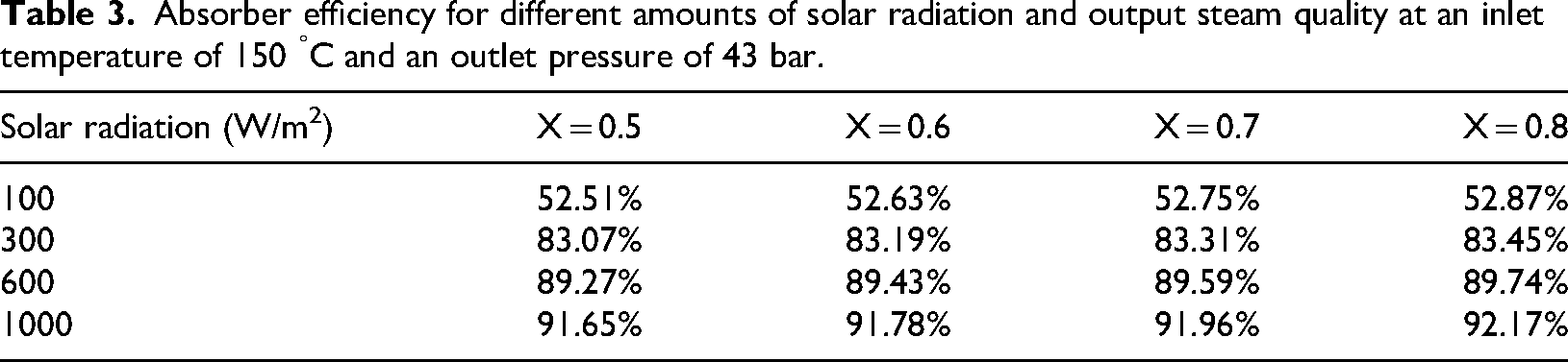
Figure 8 illustrates the pressure variation along the absorber tube under the specified inlet conditions. As shown, the pressure decreases gradually in the upstream section (0–3.8 m), where the working fluid remains in the single-phase liquid state. In this region, frictional losses are moderate, resulting in a smooth and relatively gentle decline in pressure.

Pressure profile along the length of the pipe for inlet temperature of 475 K, inlet pressure of 60 bar, and mass flow rate of 0.5 kg/s.
A pronounced steep drop occurs between 3.8 and 5.2 m, corresponding to the two-phase flow region. The sharp decrease in pressure is caused by vapor generation and the resulting increase in accelerational and interfacial shear stresses. This behavior is characteristic of two-phase flow, where hydrodynamic instabilities and strong density gradients significantly amplify the pressure losses.
Beyond about 5.2 m, the pressure gradient flattens as the fluid transitions into superheated steam. In this final section, the pressure decreases more smoothly, reaching 28–30 bar at the outlet.
The accurate prediction of the CHF is an essential aspect of designing a DSG system. Because thermal stresses in the solar absorber are strongly influenced by the local boiling regime, an appropriate CHF model is required to evaluate how design parameters affect both the stress level and the achievable steam production and heat-transfer rates. One reliable approach for determining CHF is the Groeneveld LUT. The LUT provides CHF values as a function of pressure, heat flux, and thermodynamic quality over a wide range of operating conditions.
Table 2 presents the CHF values obtained from the LUT for different pressures and mass flow rates. Although classical CHF correlations typically predict an increase in CHF with higher mass flux, the Groeneveld LUT exhibits several high-pressure and low-mass-flux regimes in which the opposite trend appears. The values in Table 2 fall within this specific region of the LUT, where CHF decreases as the mass flow rate and pressure increase. This behavior reflects the transition toward near-DNB conditions, in which wall superheat and local liquid availability dominate over inertial transport effects. Accordingly, the slight reduction in CHF reported here is consistent with the underlying structure of the Groeneveld 2006 LUT.
The absorber efficiency was evaluated at inlet temperatures of 150, 175, and 200 °C, and the results are shown in Figure 9 as a function of solar radiation. While higher operating temperatures typically increase thermal losses, the simulations indicate a slight rise in efficiency from 150 to 200 °C. This trend occurs because, within this temperature range, the absorber's overall heat-loss coefficient remains nearly constant due to the selective coating and evacuated-tube structure, which effectively limit radiative and convective losses. As a result, the additional heat loss at higher temperatures is minimal, whereas the useful absorbed energy remains essentially unchanged under the fixed mass-flow rate and optical conditions. Therefore, the highest efficiency is obtained at 200 °C, and the DSG mode yields the best overall absorber performance in this study.

Adsorbent efficiency in terms of solar radiation for different temperature values at 102 bar, mass flow rate of 1 kg/s, and steam quality of 0.8.
Exergy analysis of the receiver section
To complement the thermal analysis, an exergy-based assessment was performed for the receiver section of the parabolic solar collector. The exergy balance was formulated by accounting for the absorbed solar radiation, conductive heat transfer through the absorber wall, convective interaction with the surrounding air, and radiative losses to the ambient. The results are presented in Figure 10, which illustrates the distribution of the exergy destruction ratio among the major loss mechanisms.

Distribution of exergy destruction ratio in the receiver section at G = 900 W m−2 and T0 = 298 K; comparison of conduction, convection, and radiative losses.
As shown in Figure 10, radiative and ambient losses constitute the dominant contribution to the total exergy destruction, representing 44.9 % of the total. Conductive losses through the absorber wall account for 31.8 %, whereas convective losses contribute 23.3 %. The calculated overall exergy efficiency of the receiver section lies within the range of 35–38 %, which aligns well with typical performance reported for DSG receivers operating under a solar irradiance of 900 W m−2 and a reference temperature of 298 K.
This analysis demonstrates that radiative interactions between the absorber and its surroundings are the primary source of irreversibility. Consequently, enhancements in selective surface coatings and optimization of the glass envelope emissivity have significant potential to improve receiver performance. Furthermore, the relative contributions of conductive and convective losses suggest that improved thermal insulation and the integration of secondary heat-recovery strategies could further enhance the overall exergy efficiency under practical operating conditions.
Conclusion
This study investigated the boiling phenomenon in DSG systems integrated into parabolic trough solar collectors. Solar thermal power plants equipped with LPCs consist of long, parallel rows of concentrators. Each concentrator features parabolic reflective surfaces made of glass mirrors mounted on a structural support frame. The receiver unit comprises an absorber tube coated with a selective surface and enclosed within a Pyrex glass envelope positioned along the focal line. The receiver assembly is supported at both ends and attached to the main structural pylons.
In conventional plants, the use of thermal oil as the heat-transfer fluid introduces considerable maintenance challenges and environmental concerns. Consequently, the transition toward DSG technology has become increasingly attractive. In this research, an optical model for the parabolic reflector was first developed. Subsequently, the heat-transfer equations governing the absorber tube were formulated, and all relevant heat-loss mechanisms for this configuration were incorporated. The governing equations were then solved to evaluate the axial temperature distribution of water along the absorber.
Furthermore, based on two-phase flow pressure-drop correlations, the variation of pressure along the tube was determined. The optimal steam quality was identified according to the overall system efficiency. Using the predicted steam quality under different pressure and mass flow rate conditions, the CHF for the DSG system was evaluated, enabling the selection of an optimal pressure and mass flow rate to minimize thermal stress in the receiver. The main observations are as follows:
As the fluid moves along the pipe, its temperature increases, and due to the increase in the temperature of the collector components, their heat exchange with the environment increases. By adjusting the mass flow rate, the thermodynamic state of the working fluid at the outlet can be effectively controlled in terms of steam quality. For an irradiance level of 1000 W/m2, the fluid remains in the subcooled liquid state over approximately the first 100 mm of the tube. Further downstream, it enters the two-phase boiling region, where the vapor quality gradually increases along the flow direction until complete evaporation (x = 1) is attained at a distance of about 400 mm from the inlet. When the imposed solar irradiance is reduced, the available heat input decreases, leading to an extension of the subcooled liquid region toward the outlet and a corresponding delay in both the onset of boiling and the location at which dryout occurs. The pressure drop in the single-phase (only liquid (from 0 to 100 mm) and superheated (from 430 to 600 mm)) parts is very low compared to the two-phase area; But in the two-phase region (from 430 to 100 mm), sudden changes in pressure occur and the slope of these changes increases with the increase in steam quality. Accordingly, the pressure changes in the two-phase region are usually severe and this problem provides problems in the field of designing this type of facility. It was determined that the highest absorption efficiency was achieved in the direct steam production system.
Footnotes
Abbreviations
Ethics approval
No ethical approval was needed for this study, as it is based entirely on publicly available literature and involves no original experiments or personal data.
Funding
The authors received no financial support for the research, authorship, and/or publication of this article.
Declaration of conflicting interests
The authors declared no potential conflicts of interest with respect to the research, authorship, and/or publication of this article.
Availability of data and materials
The authors confirm that all data and materials used in this study are openly available and have been appropriately referenced in the article.