
Abstract
Grounding systems play a very important role in ensuring the safety of individuals and equipment against electric shock hazards, and they contribute to the performance of equipment and protection systems during fault occurrences in high-voltage substations as well as in distribution systems. In the design of an electrical grounding system, the total ground resistance, the layout of ground rods, and their dimensions must first be determined. Moreover, the grounding system should be designed in accordance with international standards. The authors of this valuable study address the practical problem of designing a 220/110 kV substation grounding grid that is more secure and trustworthy. Employing CYMGRD software aligns with the IEEE 80 standard, considering important subterranean elements such as soil resistivity and seasonal moisture fluctuations. Future studies must, however, look at how it behaves in unforeseen circumstances, such as shifting faults and climate conditions, to completely guarantee its dependability. Ground potential rise is effectively set at 5734.72 V by a modeled grounding scheme with a grid resistance of 0.147 Ω, satisfying safety demands. Step and touch voltages are kept within safe bounds without needless complication by the design's careful coordination of mesh size and ground rod location. The simulation-validated suggested design provides a workable and practical solution for substation grounding. In this article, design solutions for single-phase-to-ground and double-phase-to-ground faults that may occur in a plant and can lead to problems such as increased ground potential and consequently dangerous touch and step voltages, are proposed in compliance with the IEEE 80 standard. These solutions aim to correct the grounding network and are structured in such a way that the layout of ground rods is optimized to keep touch and step voltages within permissible limits, thereby increasing the reliability of the grounding network.
Keywords
Introduction
Protection schemes are of great importance for distribution networks, and distribution network equipment is still very expensive and requires large investments. The protection schemes created should increase the return on these large investments and increase the reliability of the grid (Guide, 2002). The grounding system in distribution networks is used to provide safety against electric shock and reduce damage to electrical and electronic equipment. The grounding system is also a predetermined path that can protect against leakage currents from faulty electrical equipment, lightning, transient harmonics, high-frequency noise, or electrical load return to generators or smart microgrids (Kamel and Kermanshahi, 2010). Therefore, the earthing system used to return fault currents or electrical loads at frequencies of 50 and 60 Hz, which are connected to the neutral of transformers and generators (Saini and Kapoor, 2012). Connecting the grounding system to the reference ground is one of the important goals in minimizing transient voltages.
The method of connecting the grounding system to the reference ground is created by burying electrodes at several points of the ground, which, if installed correctly, is considered an important factor in the grounding system (Scaddan, 2022). Soil plays a very important role in grounding systems. Each layer of soil can have a small electrical resistance to ground currents. Electrical resistance between soil layers plays a different role. The earthing system is very important in many countries of the world and is considered very important for the protection of domestic and industrial electrical equipment. The suggested precise and useful time-domain model demonstrates that soil resistivity dominates the grounding system's transient solution to lightning strikes, but conductor characteristics like conductivity and diameter have little to no effect (Liu et al., 2001). Providing a holistic framework is a limitation of the study. The PRED (Polynomial Regression from Database Method) technique is a groundbreaking computational approach validated through extensive simulation and implementation, using short-distance data to accurately compute touch/step voltages and earth resistance in urban substations (Raizer et al., 2017). Variations in grounding resistance, conductor sizing, and touch/step potential compliance across power station earthing layouts—evaluated using CYMGRID software and compared with IEEE 80-2000 analytical techniques—were analyzed, highlighting the hazards associated with over-dimensioning or underestimating grounding parameters (Ilenin et al., 2018).
Measures to minimize the risk of indirect contact, as outlined in general electrical installation guidelines, can be effectively implemented through proper earthing practices (Sunarto et al., 2022). Earthing system design formulas in international grounding standards, which are used to calculate electrical resistance for specific soil resistivity ranges, have been reviewed in detail (Al-Shawesh et al., 2021). The influence of earthing systems on domestic electrical installations in the San Yani Municipality of the Republic of Ghana was evaluated through a comprehensive assessment and prediction of earthing resistance (Nti et al., 2020). Microgrid protection performance under various grounding schemes—namely TN, TT, and IT—was analyzed, demonstrating that the TN grounding configuration connected to the main grid provides the most effective protection against different types of faults (Rashad Mohammedeen et al., 2011). The effects of soil structure, particularly the resistivity of the surface layer, on earth system impedance and ground potential rise (GPR) were investigated, emphasizing the significant impact of soil-layer parameters on grounding performance (Mohamad Nasir et al., 2021). The performance of earthing systems under challenging environmental conditions has been widely examined, including electrode placement strategies, the use of bentonite to reduce low-frequency resistance and increase conductivity, and the application of copper and steel electrodes in different soil conditions (Lim et al., 2013). The design, implementation, and measurement of a concrete-encased grounding electrode in a residential building have also been investigated to evaluate the practical performance of such systems (Shojaeian and Parhamfar, 2023). Soil resistivity and ground resistance at two distinct locations near a power substation were assessed using an earthing grid with and without rods, with results indicating that calculated and simulated values for both soil conditions fall within acceptable ranges, supported by average RMS errors of 0% for wet soil and 4.92% for dry soil (Salam et al., 2017). Further studies have shown that ground resistance decreases as electrode dimensions and ring radii increase, with calculated values closely matching experimental measurements and CYMGRD simulations, thereby validating the proposed estimation model (Akef et al., 2024). Comparisons between manual calculations and CYMGRD simulations for substation grounding design have revealed that simulation-based methods are more efficient, reduce computation time, and offer visual insights into safe and unsafe grounding areas (Amin et al., 2021). Potential limitations in previous research include uncertainties in soil resistivity measurements under varying environmental conditions, limited scalability of proposed grounding models across different soil types, dependency on software simulations without extensive field validation, and insufficient consideration of dynamic fault conditions that may influence grounding performance. The present study addresses these limitations by applying simulation-based methods aligned with IEEE 80 standards and evaluating electrode arrangements to control hazardous voltages and enhance grounding reliability, even without the use of a separation factor (IEEE, 2020). Electrical incidents remain a major contributor to occupational fatalities in the United States, particularly in construction and maintenance sectors, where a high number of injuries stem from interaction with energized equipment, inadequate personal protective equipment, and poor safety practices (ESFI, 2022). Trade-off analyses in grounding system configurations have shown that some designs effectively limit ground currents while having minimal impact on ground potential rise, whereas others reduce ground voltage but exert less influence on current distribution (Saleh et al., 2022). Additional simulations using the current-sphere method have modeled current distributions in vertical rods and grid conductors, demonstrating that well-designed grounding systems play a critical role in ensuring safety, stabilizing voltage, and minimizing harmonic interference (Abdel-Salam et al., 2025). The main contributions of the present study are summarized as follows:
Developed a grounding grid for a 220/110 kV substation using CYMGRD software, achieving a low grid resistance of 0.147 Ω and GPR of 5734.72 V.
Ensured that step and touch voltages remain within safe limits by optimizing mesh size and electrode placement. Addressed single-phase-to-ground and double-phase-to-ground faults by modeling fault current split factors and applying corrective grounding strategies. Conducted detailed soil resistivity measurements using the Wenner method and incorporated temperature correction to improve accuracy. Reduced the number of ground rods by applying bentonite around fence areas, lowering project costs while maintaining safety. Calculated appropriate conductor cross-sections for different fault scenarios using both BS7430 and IEEE 80 standards, ensuring thermal and electrical safety.
Across recent studies, optimized grounding grid geometries and configurations significantly reduce ground resistance, GPR, and touch and step voltages while improving overall safety margins (Mistry et al., 2025). Comprehensive review studies further indicate that advancements in grounding grid analysis increasingly emphasize shape optimization, multilayer soil modeling, and the integration of numerical simulation tools to enhance substation safety performance (Mistry et al., 2024). Advanced simulation-based designs validated under extreme conditions—such as lightning strikes, high fault currents, and applications in nuclear or fusion facilities—demonstrate robust performance even in compact or complex substations (Adail et al., 2024). In particular, multilayer soil representations combined with non-conventional grid layouts consistently outperform traditional designs in controlling surface potential gradients. Collectively, the literature confirms that integrated analytical–numerical approaches aligned with IEEE standards yield safer, more reliable, and economically optimized grounding systems for critical power infrastructures (Wang et al., 2024).
Problem statement
In this present article, when single-phase-to-ground (LG) and double-phase-to-ground (LLG) faults occur in a plant of the earthing system, these faults can cause fault injection in the downstream and upstream systems, which in the upstream system, that is, the high-voltage side, causes an increase in the ground potential and dangerous step and touch voltages, which is the total amount of fault current that is created, which is called the split factor. The split factor means the ability of the power system to separate the fault from the unbalanced current. Considering the absence of the separation factor, the problems previously introduced can be addressed using the methodologies outlined in the IEEE 80 standard (IEEE 80, 2000). Solutions involving the arrangement of electrodes are also applied to maintain step and touch voltages within permissible limits, thereby enhancing the reliability of the earthing network. Simulations are conducted using CYMGRD software. This article begins by presenting the problem statement, followed by a description of the assumptions and information provided by the employer. Subsequently, the simulation is carried out using CYMGRD software, and the results are analyzed. The design limitations are discussed, and the most suitable proposal is identified based on these constraints. Figure 1 illustrates an improved earthing system aimed at enhancing reliability.
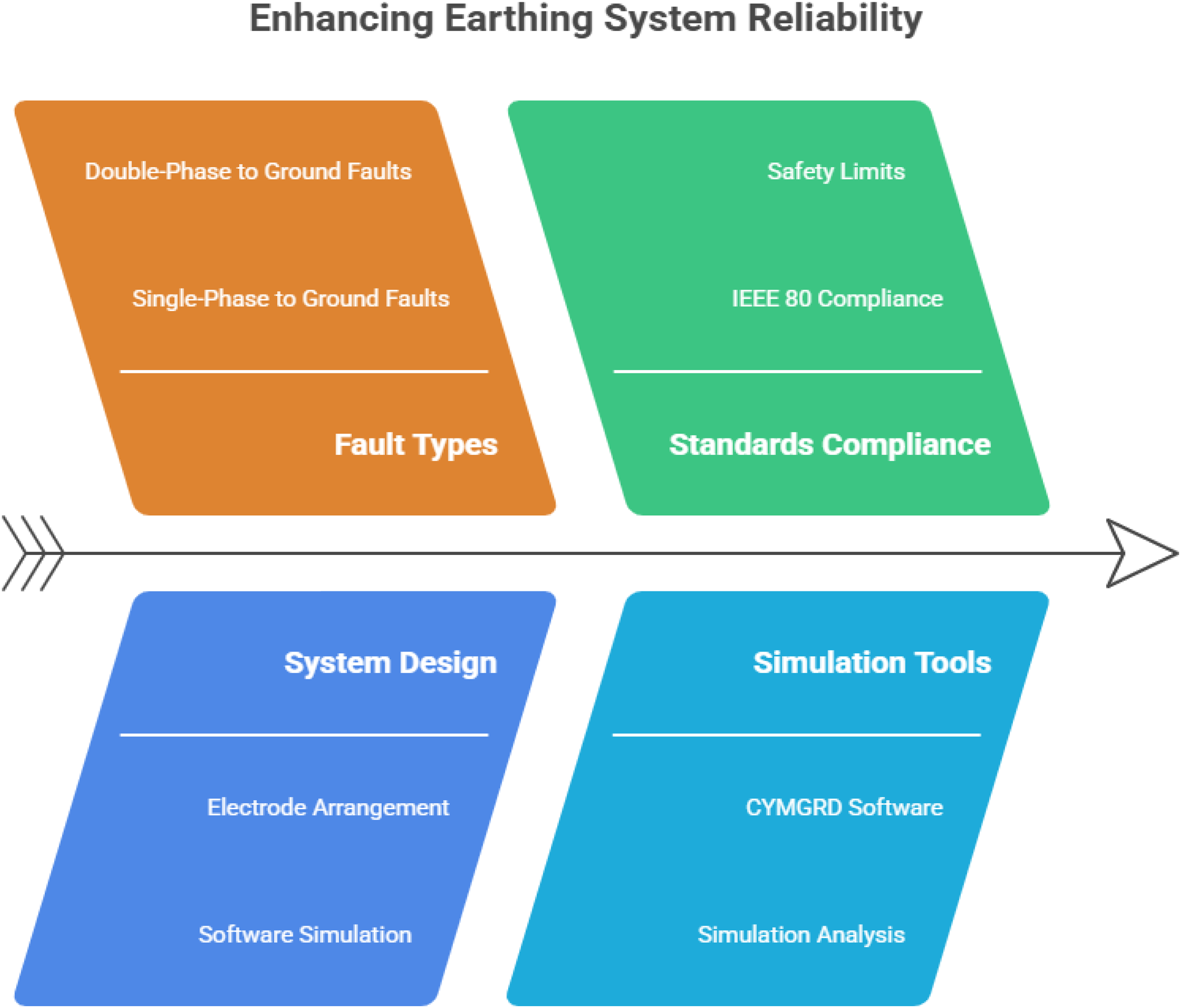
Enhancing reliable grounding systems.
Research challenge
As mentioned in this study, when single-phase-to-ground or two-phase-to-ground faults occur in the grounding system, they cause disturbances in both upstream and downstream sources. These faults in the upstream source result in issues such as increased ground potential and dangerous step and contact voltages. The high-voltage substation design for Georgia initially exhibited inappropriate step and contact voltages, and efforts were made to optimize these values using the provided solutions.
Foundational assumptions
This study presents the results of investigations conducted using the vertical electric method (Wenner) at a 220/110 kV substation. The primary objective of the survey was to determine the soil electrical resistivity. The test was carried out in April 2022, under conditions where no precipitation occurred during the survey period. The air temperature ranged from 14 °C to 17 °C. The surface soil is primarily composed of topsoil, moist lean clays, and crushed stone. The investigation, conducted using the Wenner method, is illustrated in Figure 2, where the distances between the electrodes (
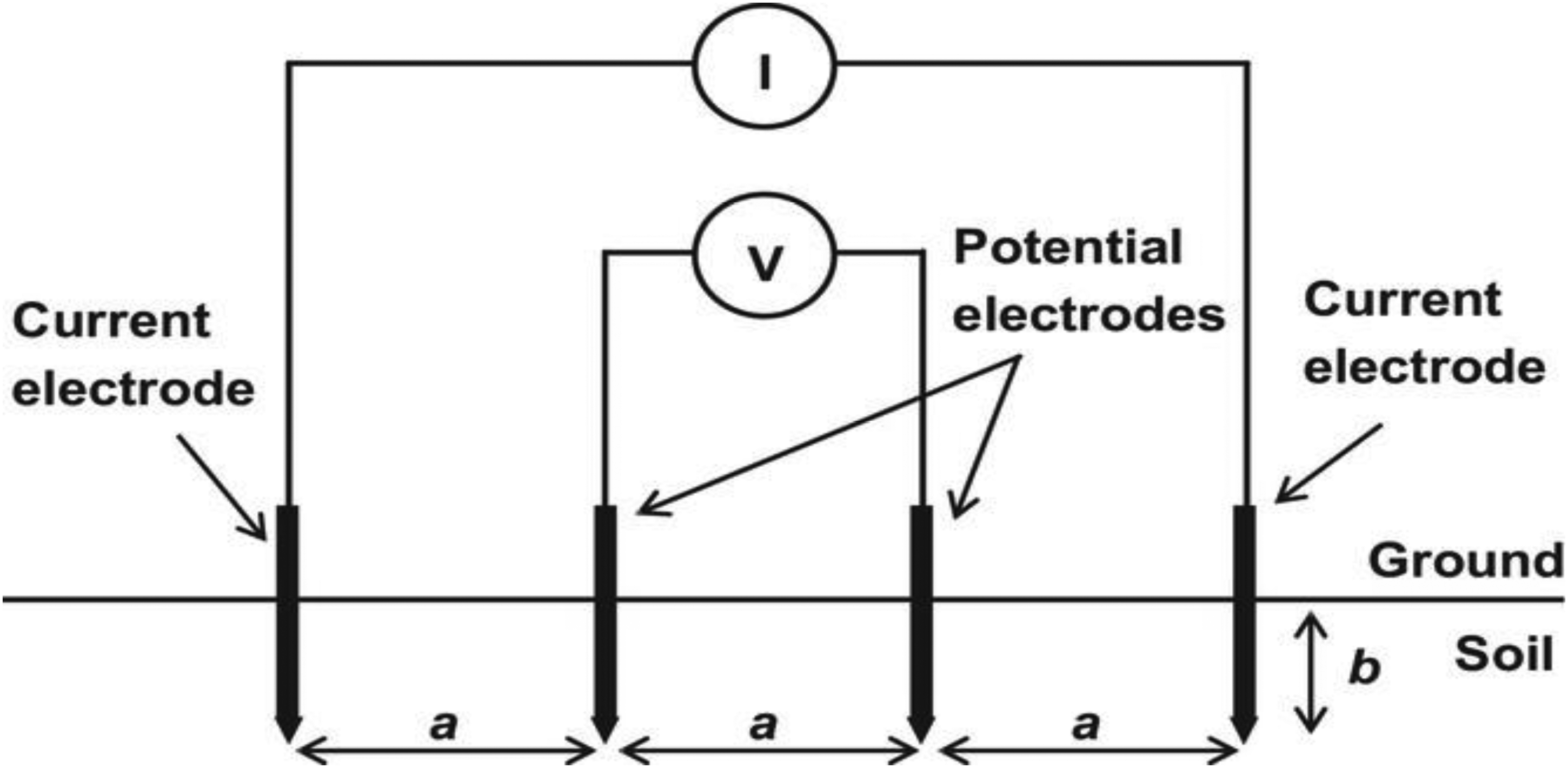
Scheme of soil resistivity measurement using the Wenner method.

Measuring apparatus: ARES-850 v5.50.
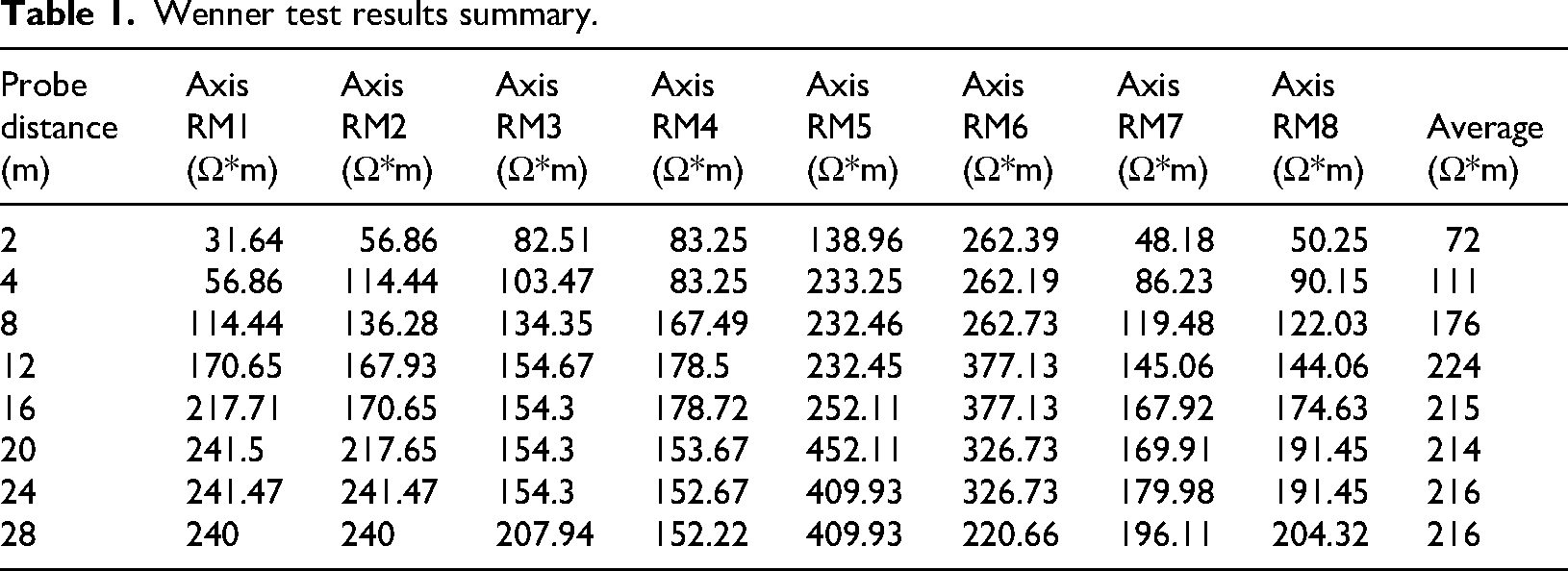
Wenner test results summary.
The calculation is based on a computer program called CYMGRD, developed by CYME International Inc. CYMGRD employs a finite element analysis algorithm, which provides greater accuracy compared to the approximate formulas outlined in IEEE 80-2000. This algorithm allows CYMGRD to analyze earthing systems with either symmetrical or asymmetrical configurations of ground conductors and rods.
The soil resistivity values used in this analysis are derived from the latest site soil investigation report, as referenced in Annex 2 (Soil Resistivity Report). Using the CYMGRD software, a soil resistance analysis is conducted, and as part of this analysis, the percentage of errors between the measured and calculated soil resistivity is determined.
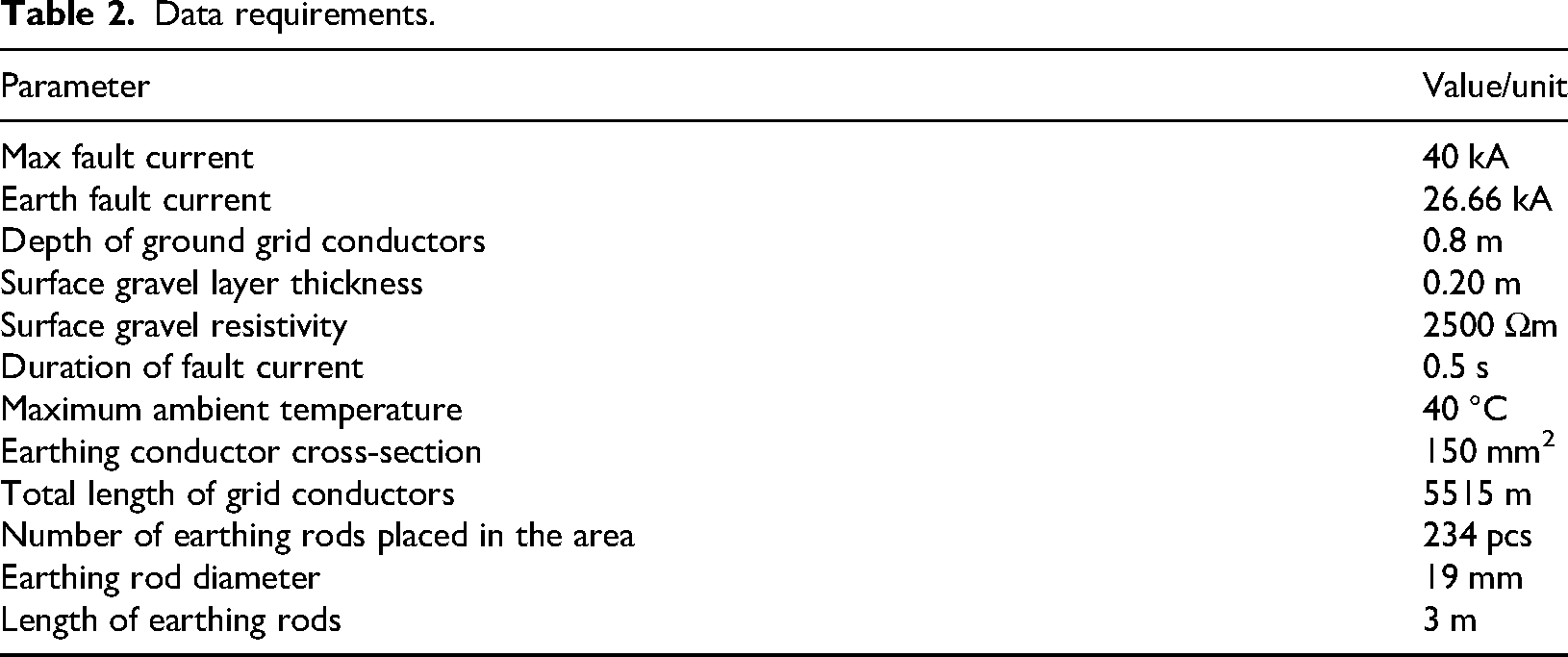
The next stage is inserting data; the following inputs are required for the calculation of step and touch potentials, as well as the grid resistance, which are presented in Table 2. The Earth grid calculation is based on a maximum earth fault current, denoted as 
Data requirements.
Here 
Substituting 
Material constant.
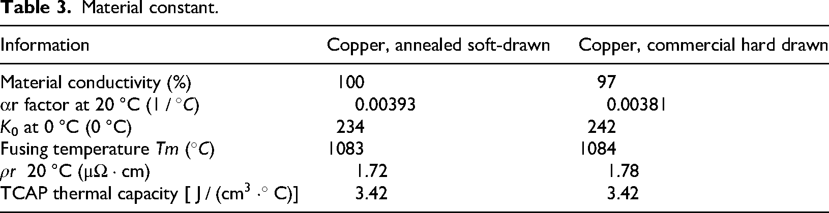
With (3), the required cross-sectional area S. The cross-sectional area of a conductor (mm2) is calculated to safely carry a given RMS current I (kA) for a duration t (seconds) without exceeding the maximum allowable temperature rise. The parameters include
Table 3 outlines material constants for two copper types, annealed, soft-drawn copper and commercial, hard-drawn copper, which are crucial in thermal and electrical performance calculations. These constants include material conductivity, resistivity, temperature factors, and fusing temperature, among others. Commercial hard-drawn copper has a material conductivity of 97%, an αr factor at 20 °C of 0.00381 (1/°C), and a fusing temperature of 1084 °C. Its resistivity (
Approach
Based on the absence of data regarding the upstream network and the plant's resistance (R) and reactance (X) values, the IEEE 80-2000 Annex C procedure is employed to address these limitations. Regarding the current contribution, four categories (A to D) are defined. Among these, the worst scenario corresponds to Category A, where 100% of the current contribution is assumed to be remote. Consequently, figures C.1 to C.16 are selected for the analysis, while figures C.17 to C.22 are excluded. For the transmission tower footing resistance, two categories are considered: (1) 15 Ω for transmission grounding (TRANS. GND) and 25 Ω for distribution grounding (DIST. GND), and (2) 100 Ω for transmission grounding and 200 Ω for distribution grounding. The most common case corresponds to the first scenario (15/25 Ω). Figure 4 presents the grounding category in this study based on IEEE (2020).
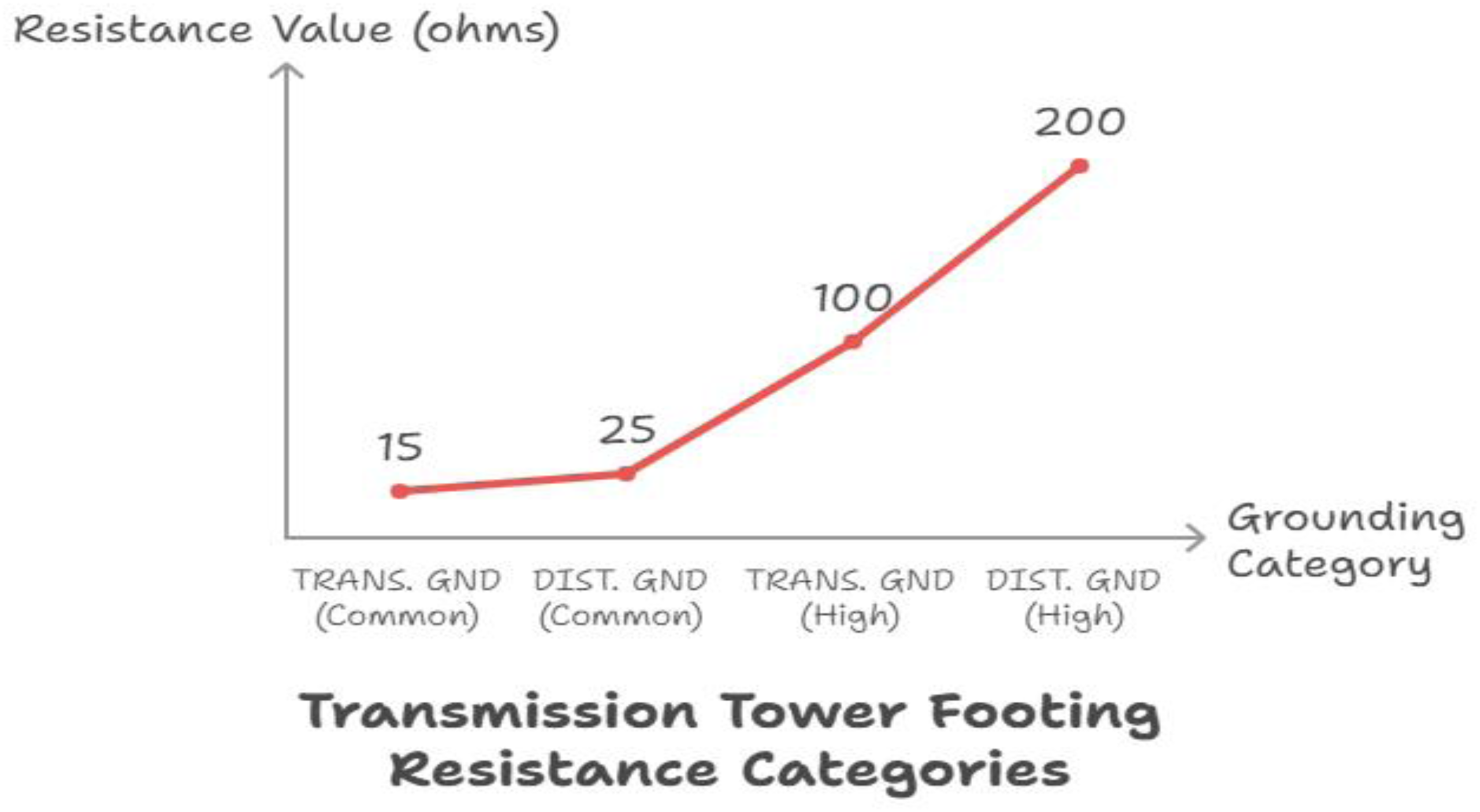
The grounding category.
Therefore, the odd-numbered figures from the selected set are utilized for further analysis. Finally, for the substation configuration, two scenarios are analyzed: (1) two transmission lines and six distribution feeders, and (2) four transmission lines and seven distribution feeders. The worst-case scenario, characterized by the higher split factor, is represented by the first scenario.
To ensure that touch and step voltages remain within permissible limits, additional ground rods were installed in the fence area. The horizontal axis of the Annex-C figures represents a grid resistance value of ∼0.147 Ω. The strategy used in this study is illustrated in Figure 4. Furthermore, the results of the consideration are illustrated in Figure 5.
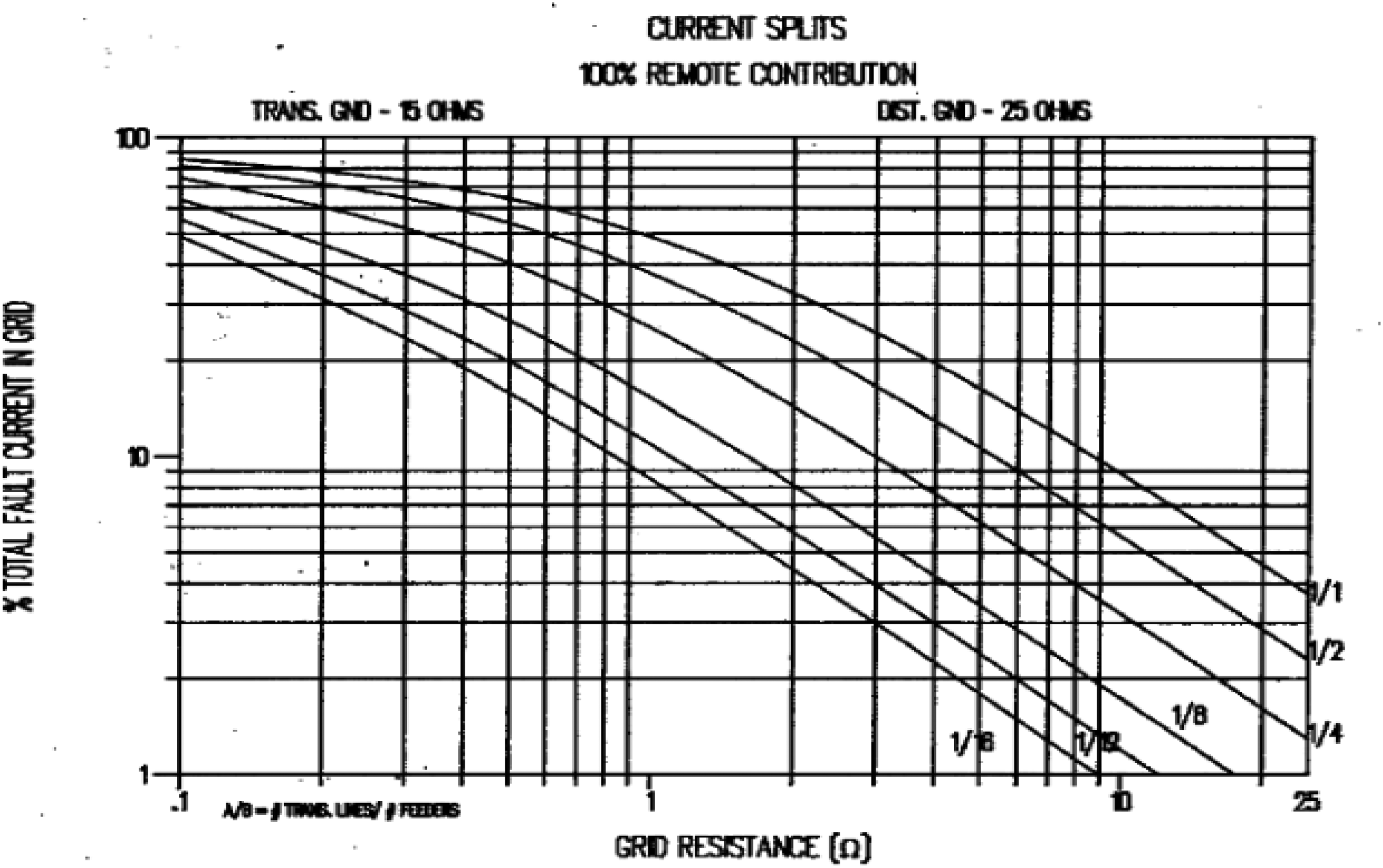
Split factor curve (IEEE, 2020).
As a safety margin, earthing compound (bentonite), which is considered a worst-case scenario, was applied around the fence area to reduce the resistance between the soil and the ground electrode. This approach minimized the number of ground rods required, thereby effectively reducing the overall project cost. The data were input into CYMGRD, which accounts for this feature exclusively for ground rods and not for horizontal conductors, although the latter also contributes to the reduction in resistance as part of the safety margin. Based on these considerations, the final grid resistance value of 0.147 Ω was achieved.
Measurement of soil resistivity
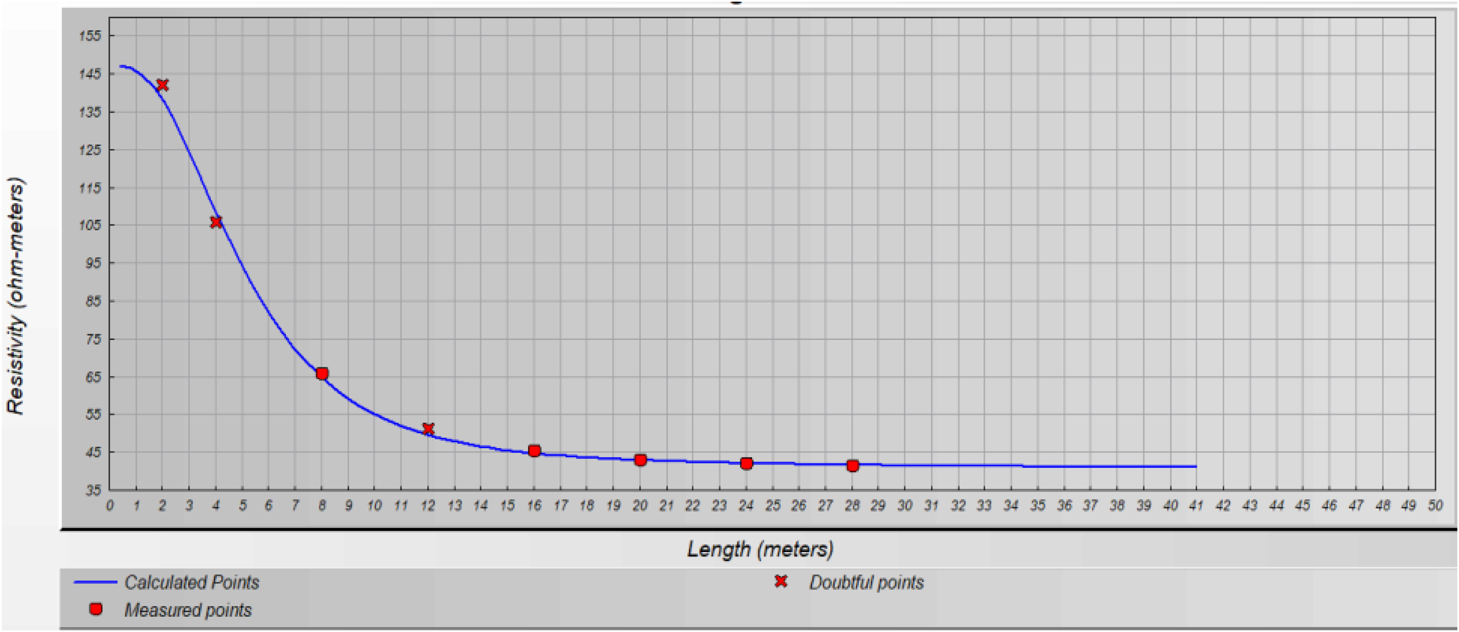
The eight measured points, along with their average value, were analyzed using the IPI2win software. Images showing the results before and after correction (inversion) are presented separately, accompanied by an error comparison table for both conditions. Additionally, the soil layer conditions for nine cases (eight measured points and one average case) were evaluated using the CYMGRD software. Figures 6 to 8 show soil layers in CYMGRD.
Examination of soil layers in CYMGRD.
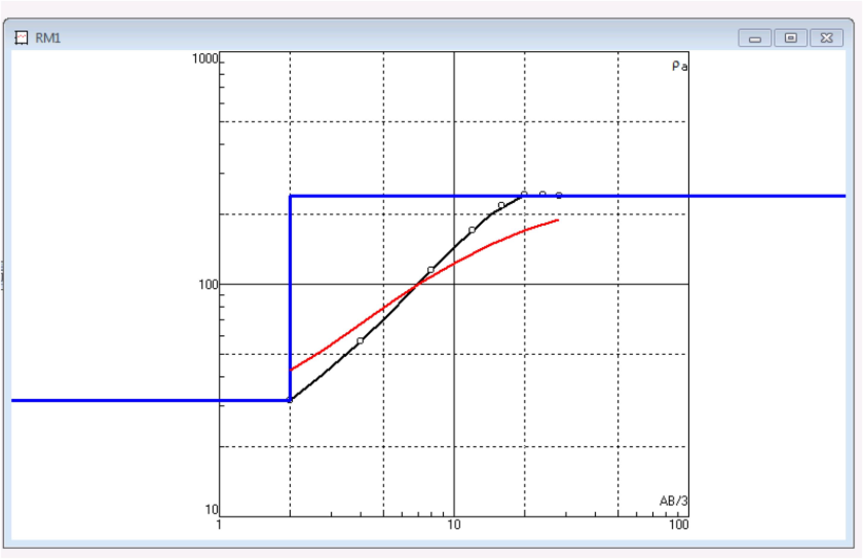
Check soil layers in IPI2win before inversion.
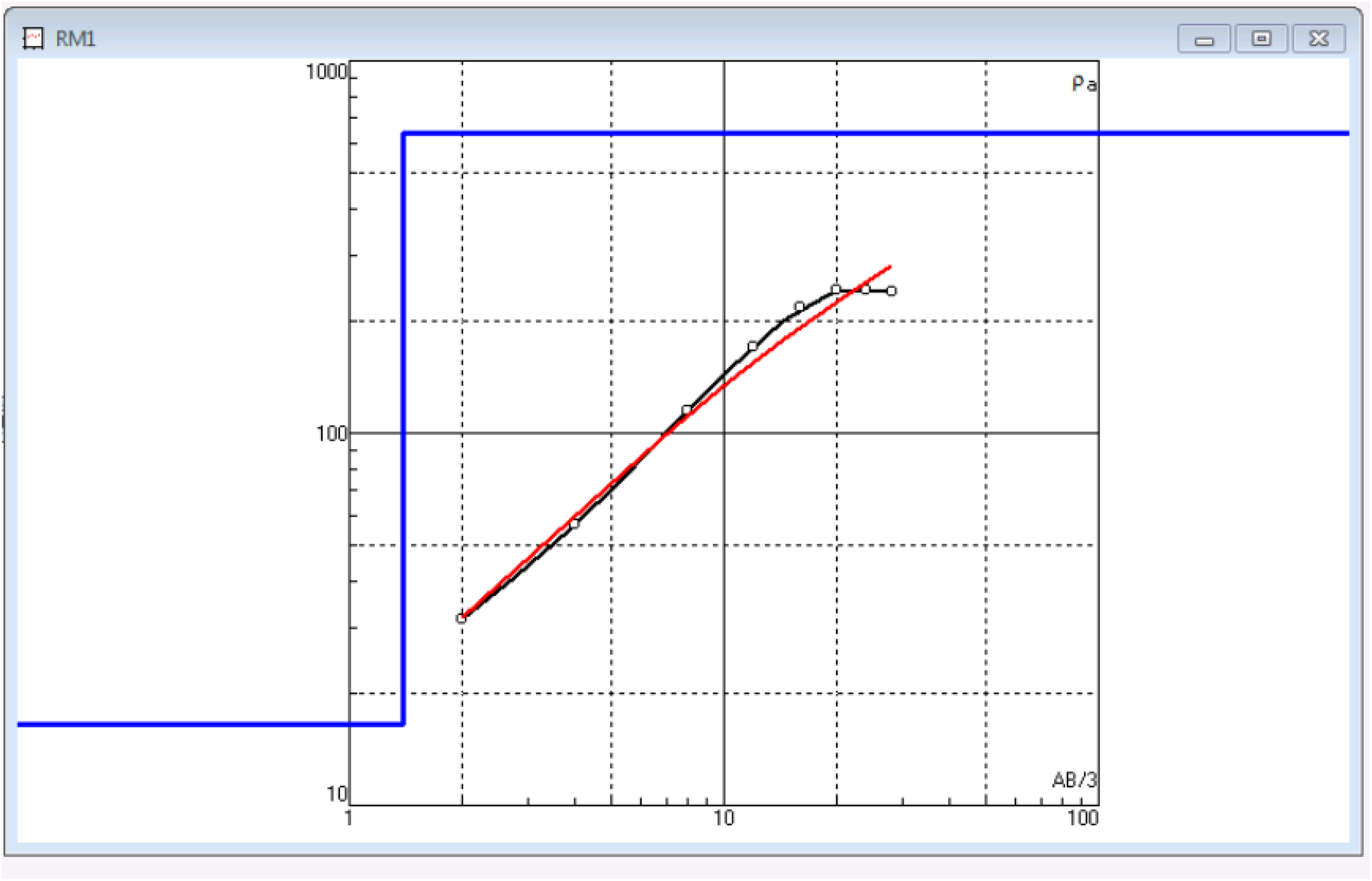
Check soil layers in IPI2win after inversion.
The temperature correction factor can play an important role in ensuring accurate measurements. It is based on the standard reference temperature of 20 °C, as specified in BS 1377-3:2018. When measurements are conducted, the temperature difference can be accounted for to maintain precision. This correction factor is particularly important for temperatures ranging between 5 °C and 30 °C, where deviations can otherwise impact the reliability of the results. Equation (4) accounts for temperature correction by adjusting the measured resistance 
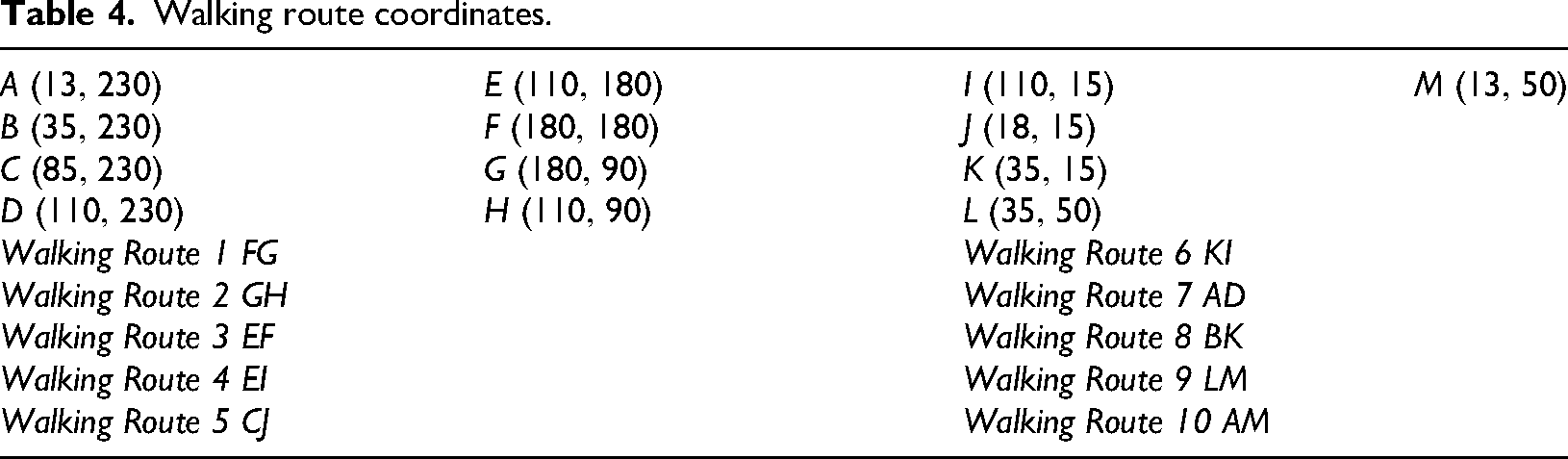
The graph of touch and step voltages and GPR has been investigated in 10 routes. The position of the beginning and end of each movement path is presented according to Table 4 and the following Figures 9 to 11, respectively.
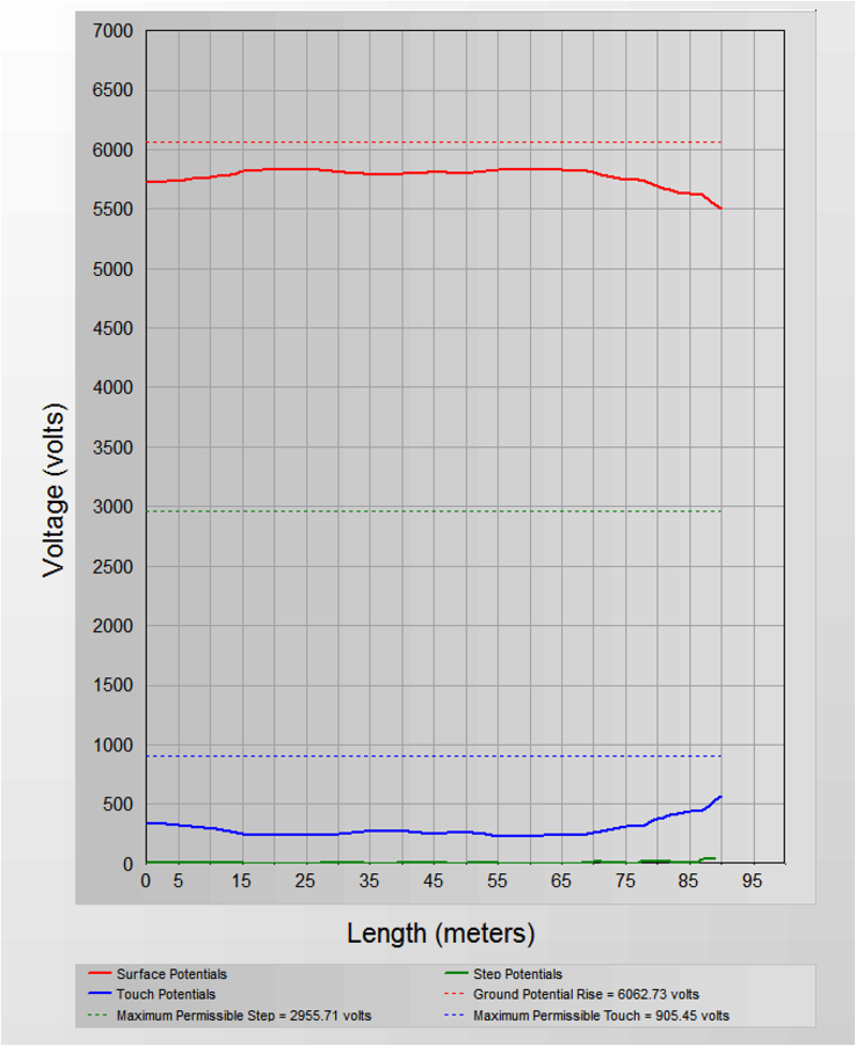
Potential profile WR1.

Walking route.

Point of origin for collecting information.
Walking route coordinates.
According to the IEEE80 standard, the best way to reduce the touch voltage of perimeter fences is to run a mesh network 1 m beyond the fences or a ring 1 m beyond the perimeter and connect it to the ground system. In some cases, to avoid the limits of the contact voltage, wall covering is used instead of a fence. The location of the fence relative to the grounding system significantly impacts touch voltage levels. If the fence is outside the mesh network and connected to the ground system, the touch voltage may exceed permissible limits. When the fence overlaps with the ground system, connecting it to the network keeps the touch voltage close to acceptable levels. However, if the fence is entirely within the grounding system, its connection ensures much lower touch voltage values, emphasizing the importance of proper positioning and integration for safety.
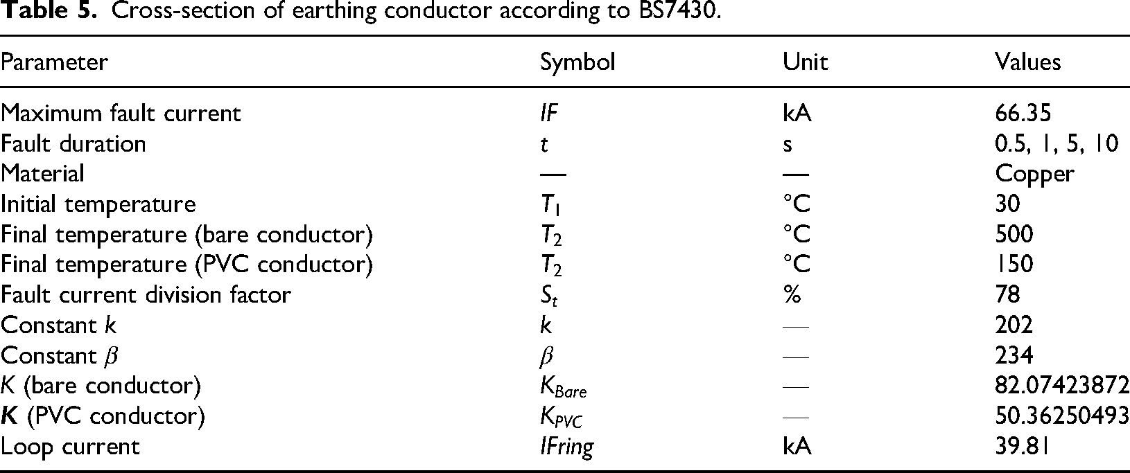
Proper consideration of the cross-section of grounding conductors can be crucial to ensure their ability to withstand fault currents and maintain system safety. In the system of connecting to the ground in the form of a grid network, considering that the current is discharged in two paths at the connection point, therefore, the dividing factor of 60%, as the current passing through the electrode ring or mesh is considered, and this conductor must be able to withstand this current. But in other branches, the division coefficient is not considered because the entire fault current will pass through this conductor. Therefore, the cross-section of the conductor ring or mesh will be different from the cross-section of the branches. On the other hand, in the place of branches, if it is required to use coated wire, considering the need to apply the heat tolerated by the coated conductor, this cross-sectional area should be reconsidered. Figure 12 illustrates a safe grounding fence. According to Table 5, the BS7430 standard, the cross-sectional area in the mesh equals 50.44 mm2, in the branches with uncoated wire, it equals 84 mm2, and in branches with coated wire, it will be equal to 143.7 mm2. The findings from cross-section calculations are presented in Table 6.

Safe grounding fence.
Cross-section of earthing conductor according to BS7430.
Results for cross-section calculations.
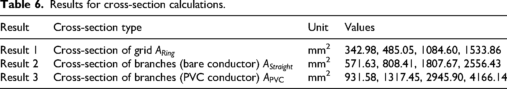
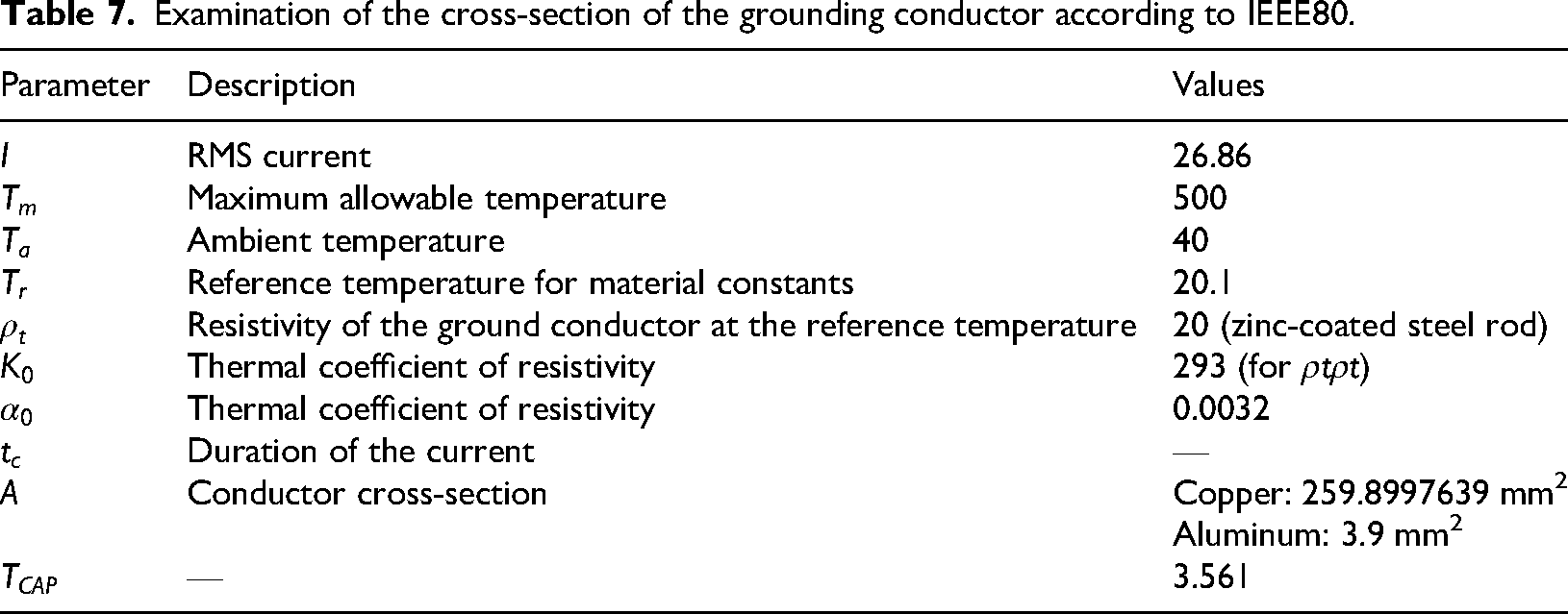
Table 7 provides parameters related to the cross-section of ground conductors, including current ratings, temperature limits, resistivity characteristics, and calculated cross-sectional areas for different conductor types, such as copper and aluminum, aligning with IEEE80. IEEE states that the cross-sectional area is somewhat more than BS7430.
Examination of the cross-section of the grounding conductor according to IEEE80.
Summary of modeling
IEEE 80 serves as a fundamental framework for the analysis and design of grounding systems. This standard incorporates a range of methodologies for evaluating grounding configurations to protect individuals and electrical equipment from hazards associated with unintended currents. One of the primary parameters assessed in grounding system design is the soil's electrical resistivity. Establishing an effective electrical connection between system components and the earth—allowing safe dissipation of fault and leakage currents—requires proper grounding system design and implementation. Different types of grounding systems may be adopted depending on the intended function, one of which is the efficient transfer of fault currents into the earth to ensure the safety of personnel and equipment across various facilities.
The ground electrode plays a key role in safely transferring electrical currents and loads into the soil. The earth itself is a conductive medium with a finite resistance, meaning that every buried electrode has an inherent resistance measured relative to a distant reference point, effectively at infinity. Several factors influence this resistance, including soil resistivity and the design, geometry, and placement of electrode components. Additionally, electrode resistance may be affected by surface potentials generated during fault events. Therefore, it is essential to thoroughly investigate soil properties as well as environmental and human-body electrical characteristics before constructing a grounding system to ensure overall safety and performance.
At Taraz Nir Adak Company, grounding system design is performed using specialized software and is guided by well-established international standards such as IEEE-80, IEEE-81, BS 7430, IEEE 142, and IEEE 1100. Numerous considerations related to grounding design and installation require reference to the appropriate standard depending on the specific application. Grounding systems are generally categorized into two groups: electrical grounding and protective grounding. Protective grounding takes precedence in all facilities due to safety requirements. Calculations of overall ground resistance and step and touch potential distributions are performed using the finite element method. The following parameters are required for designing a protective grounding system:
- Soil resistivity and soil type - Site dimensions - Maximum ground-fault current - Operating time of protective relays corresponding to fault current - Maximum tolerable voltage for personnel and equipment - Site layout
Three major factors influencing soil resistivity are soil moisture, salt content, and temperature. Moisture is the most influential of these, as it varies significantly with climate and tends to be much lower in rocky soils. Low temperatures can increase soil resistivity; thus, IEEE Standard 80 specifies an assumed frost depth of 80 cm.
The following three models are commonly used to calculate earth electrode resistance:
Uniform model: Soil resistivity remains constant with depth. Non-uniform model: Soil properties and resistivity vary with depth. Two-layer model: The soil is represented as an upper layer with resistivity ρ₁ and thickness h, above a deeper layer with resistivity ρ₂.
Identifying the appropriate soil model is critical in grounding system design, and the two-layer model is often used for high-voltage substations due to its ability to represent dominant resistivity gradients.
Mesh system analysis typically begins with a site visit to review the substation layout so that all equipment and structures can be accurately represented in the design. The initial grounding layout is then developed based on the following principles:
A continuous copper conductor is installed around the perimeter of the grounding area to prevent current concentration and reduce potential gradients at conductor endpoints. Within this loop, parallel uncoated copper conductors with a minimum cross-section of 50 mm2 are installed at depths between 0.5 and 1.3 m, depending on local frost depth. Conductors are spaced 3–7 m apart and are reliably interconnected at their intersections, preferably using exothermic welding. Ground rods may be placed at the corners and intersections of mesh conductors. In regions with multilayer soil or high resistivity, longer rods (up to 30 m) may be used or placed in drilled wells to reduce overall grounding resistance. Increasing the number of conductors in the mesh has only a modest effect on lowering grid resistance but significantly reduces surface potential gradients.
To further reduce ground resistance, resistivity-reducing materials such as bentonite and chemical backfills may be used. The CYMGRD software assists in the grounding design process by automatically recommending optimal mesh configurations and conductor sizes. This software was used in the present study.
Results and discussion
In the figures, one more ring has been added to the initial network, and the simulation has been performed again, and the voltage and step are within the range. Figures 13 and 14 display the results of the simulation and the three-dimensional output touch voltage, respectively (Table 8).

Potential contour plot.

Three dimensiona (3D) output touch voltage.
Grid analysis report.
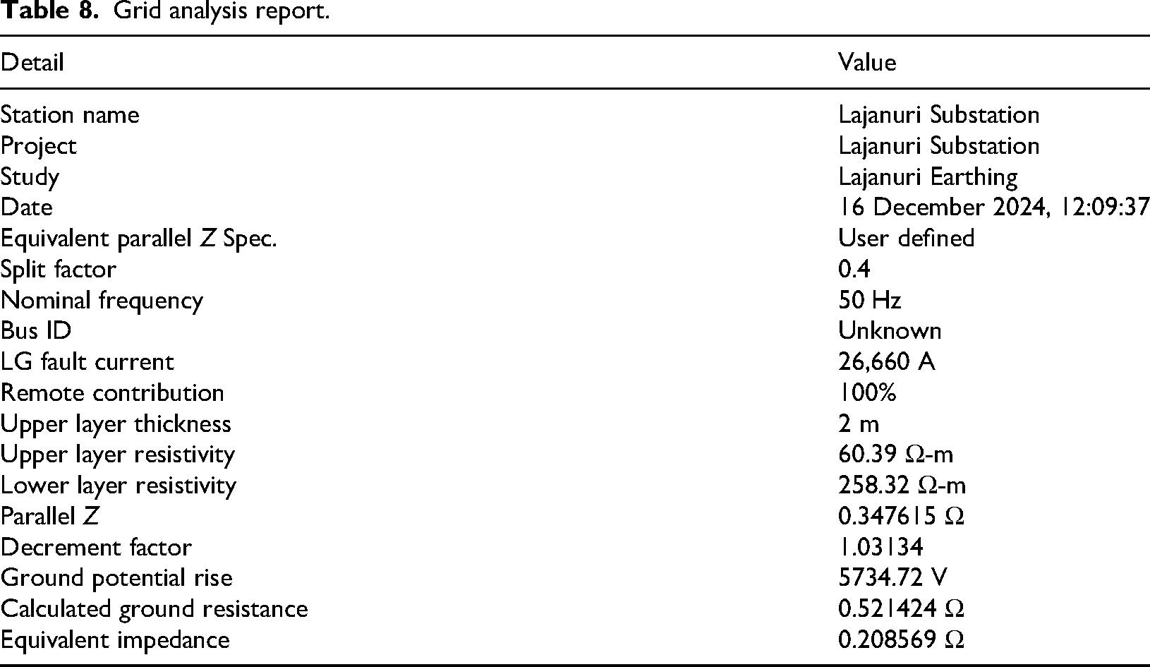
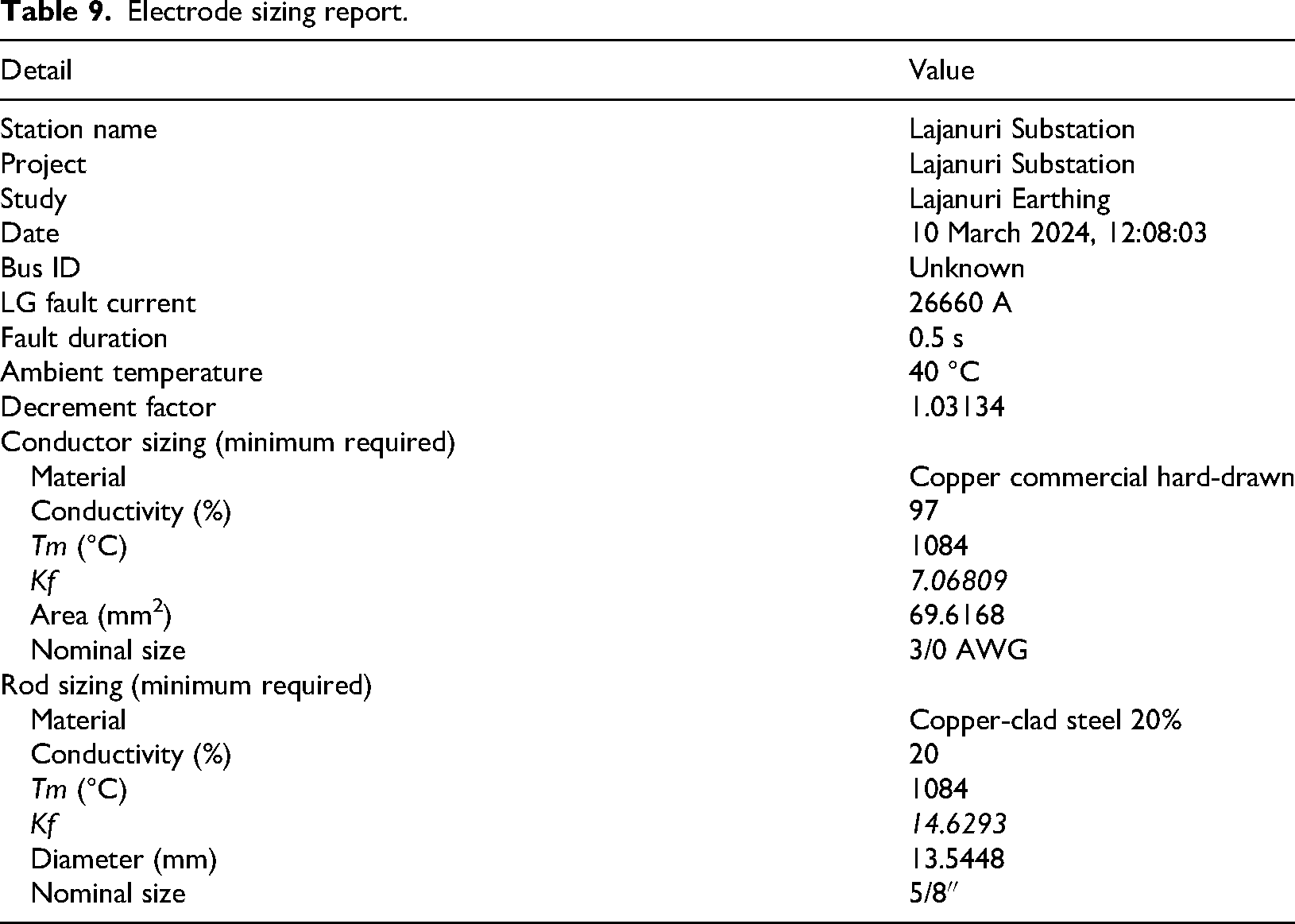
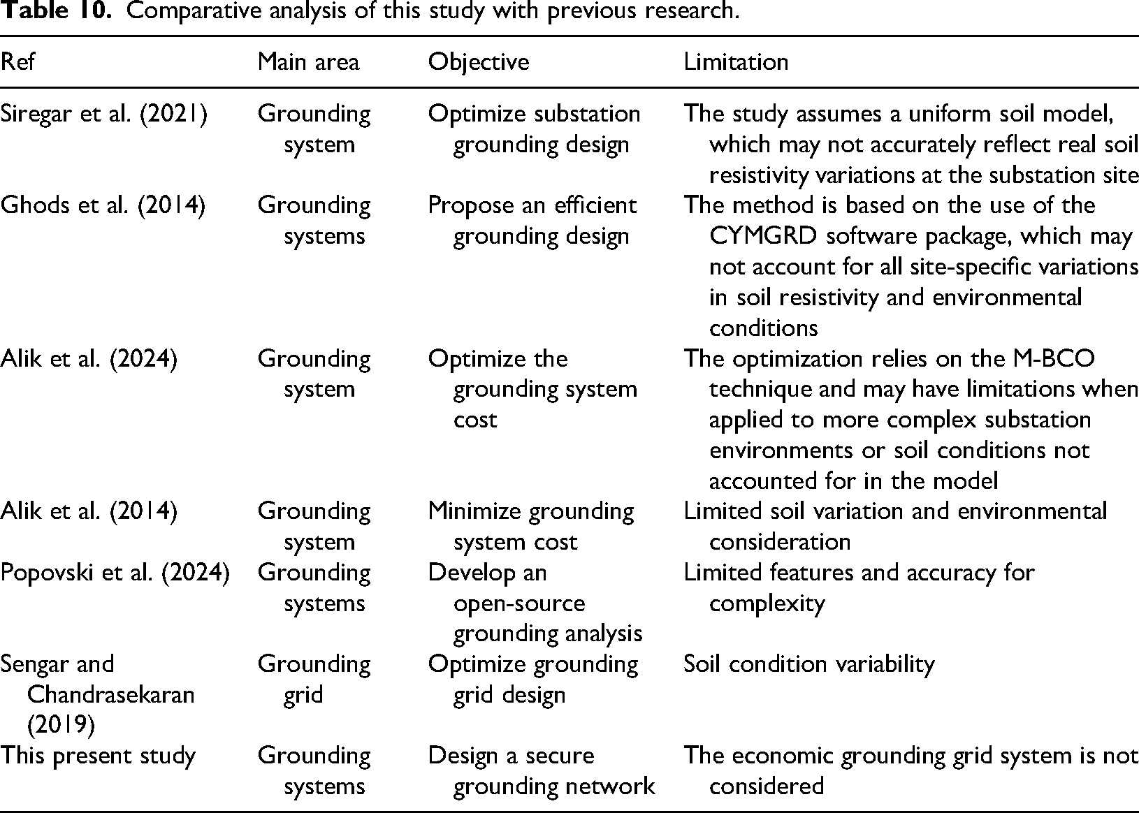
Table 9 indicates that due to the LG fault current at the Lajanuri Substation, the dimensions of conductors need to be thoroughly analyzed for effectiveness as well as safety. To ensure proper conduction and minimize losses, the AWG size should be at least 3/0. The improved design reduces harmful contact and step voltages, ensures low ground resistance, and lowers GPR to 5734.72 V. While a comprehensive photovoltaic plant design was presented in previous work, its main limitation was the absence of an earthing system design, which the present study aims to address (Parhamfar and Zabihi, 2025). Although increasing power output is crucial for any power system installation, the grounding system also plays a fundamental role in ensuring protection and operational safety, a topic that was only partially examined in earlier research (Zabihi et al., 2024). Table 10 provides a comparison between the present study and previous studies. Future work may incorporate cost analysis and optimization techniques to develop an improved and more effective grounding design.
Electrode sizing report.
Comparative analysis of this study with previous research.
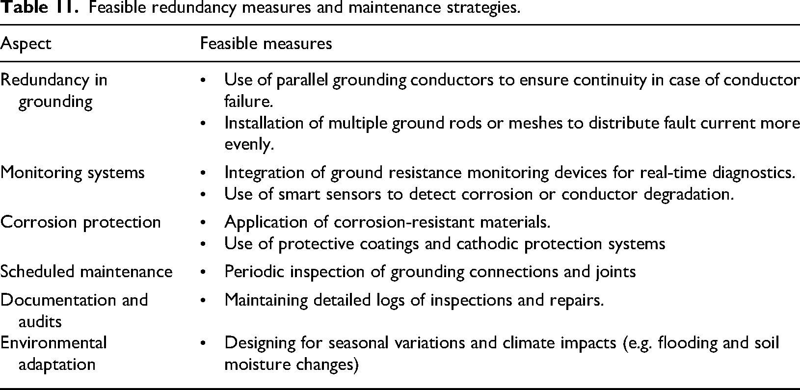
This present study presents a comprehensive grounding design for a 220/110 kV substation that not only complies with IEEE 80 standards but also introduces practical enhancements tailored to site-specific conditions. Unlike conventional designs, it integrates detailed soil resistivity profiling using the Wenner method with temperature correction and applies bentonite strategically to reduce electrode count and project cost, demonstrating a novel approach to economic optimization. While CYMGRD simulation is a core tool, the study goes further by analyzing fault scenarios, conductor sizing, and mesh configurations to ensure safety under worst-case conditions, achieving a low grid resistance of 0.147 Ω and GPR of 5734.72 V. These results validate the design's effectiveness in controlling touch and step voltages, and highlight its relevance for future implementations, especially in regions with variable soil and fault conditions. Future research could build upon the current findings by conducting a comprehensive economic analysis of substation grounding system designs. This would involve evaluating the cost-effectiveness of various electrode configurations, soil enhancement techniques, and material selections, as demonstrated in this study. By integrating life-cycle cost assessments and quantifying the financial benefits of optimized rod placement and reduced grid resistance, such analyses would provide valuable insights for utility planners and engineers seeking to balance safety, performance, and budget constraints in large-scale infrastructure projects. Table 11 provides strategies that not only reinforce system reliability but also align with suitable practices for asset management and operational safety.
Feasible redundancy measures and maintenance strategies.
The present grounding design introduces several advancements beyond conventional CYMGRD-based approaches. First, it integrates temperature-corrected, multilayer soil modeling using both Wenner measurements and IPI2win inversion, whereas most CYMGRD studies rely on uncorrected or uniform soil assumptions. Second, the design combines IEEE-80 Annex-C split-factor analysis with site-specific grid optimization, enabling more accurate worst-case LG and LLG fault evaluations. Third, the study employs targeted bentonite applications to reduce the number of ground rods, a cost-optimization technique rarely incorporated in CYMGRD simulations. Fourth, conductor sizing is assessed using both BS7430 and IEEE-80 standards, providing dual-validated thermal and mechanical safety margins. Finally, the design extends beyond static simulations by evaluating fence interaction effects, mesh extensions, and walking-route voltage profiles, offering a more comprehensive safety assessment than conventional CYMGRD-only analyses.
The split factor plays a critical role in determining how much of the fault current flows into the grounding grid, and, therefore, directly influences GPR as well as touch and step voltages. As the split factor increases, a greater portion of the upstream fault current enters the substation grid, leading to a proportional rise in GPR. For instance, at the modeled design value of 0.40, the GPR is 5734.72 V. If the split factor increases to 0.60, the injected fault current rises by 50%, which would raise GPR by approximately the same proportion, potentially exceeding 8500 V under the same soil and grid resistance conditions. Touch and step voltages exhibit similar sensitivity: higher split factors increase local potential gradients, especially near conductor intersections and fence boundaries, pushing them closer to or beyond IEEE-80-permissible limits. Conversely, as the split factor decreases toward 0.20–0.30, reductions in GPR and surface potentials improve safety margins, often eliminating the need for additional electrodes or soil enhancements. This qualitative analysis highlights that the grounding system's robustness is strongly influenced by split-factor uncertainty, underscoring the importance of Annex-C evaluation in the absence of upstream impedance data.
Soil moisture strongly modulates apparent soil resistivity and, therefore, the effective grid resistance, GPR, and local step/touch potentials. Increased moisture (wet season) generally lowers near-surface resistivity, reducing grid resistance and GPR for the same fault current; conversely, dry conditions raise resistivity and can substantially increase GPR. For the present site, if the near-surface resistivity increases by a factor of 1.5–3.0 in dry months (a conservative and site-dependent range), the effective grid resistance and resulting GPR would scale approximately by the same factor—for example, a baseline GPR of 5734 V could rise toward ≈8.6–17.2 kV under much drier conditions if grid geometry and all other parameters stay unchanged. Higher resistivity also steepens local potential gradients, increasing maximum touch and step voltages and enlarging unsafe zones around electrodes and fences. Seasonal resistivity swings, therefore, justify designing to the worst credible (dry-season) case or applying mitigations such as deeper conductors/rods, denser mesh near perimeters, increased use of bentonite or other soil conditioners, targeted watering or moisture-retention layers, and improved fence bonding.
Conclusion
This study presents a comprehensive grounding system design for a 220/110 kV substation, addressing critical safety challenges arising from single-phase-to-ground (LG) and double-phase-to-ground (LLG) faults in high-voltage networks. Such fault conditions significantly increase ground potential and result in hazardous touch and step voltages, posing serious risks to personnel safety and equipment integrity. To mitigate these risks, the design strictly adheres to IEEE 80 standards, integrating advanced simulation techniques with real-world soil characterization. Using CYMGRD software, the proposed grounding layout incorporates site-specific parameters, including multilayer soil resistivity measured via the Wenner method, seasonal moisture variations, and temperature corrections. The resulting model achieves a ground potential rise (GPR) of 5734.72 V and a grid resistance of just 0.147 Ω—both well within the IEEE 80 safety thresholds. This demonstrates the effectiveness of the electrode mesh optimization and conductor sizing strategies applied in the study. Additionally, the use of bentonite in targeted fence zones proved to be a cost-effective enhancement, reducing the number of required ground rods while maintaining electrical performance. The design's ability to maintain safe voltage levels under worst-case fault scenarios confirms the reliability and practicality of the proposed approach, especially in substations with complex or variable soil conditions. This work provides a replicable and scalable grounding methodology for energy infrastructure projects. Future research could extend this approach by incorporating dynamic fault behavior, long-term soil corrosion modeling, life-cycle cost analysis, and AI-based optimization techniques to further enhance safety, resilience, and economic efficiency in grounding system design.
Footnotes
Author contributions
Mohammad Parhamfar: writing–review and editing, validation, supervision, software, and resources. Aykut Fatih Güven: writing–review and editing, writing–original draft, resources, formal analysis, data curation, and conceptualization. Mohit Bajaj and Mebratu Sintie Geremew: project administration, supervision, resources, and writing–review and editing.
Funding
The authors received no financial support for the research, authorship, and/or publication of this article.
Declaration of conflicting interests
The authors declared no potential conflicts of interest with respect to the research, authorship, and/or publication of this article.
Data availability statement
The data supporting this study's findings are available from the corresponding author upon reasonable request.