
Abstract
Undesirable power quality issues, such as harmonics, can lead to overheating of transformers, malfunctions of sensitive loads, increased power losses, and a significant reduction in the distribution system's efficiency. Nonlinear devices in the power distribution network cause current and voltage harmonics. Consequently, there is a strong need for mitigating harmonics in power networks, which is addressed worldwide through the wide application of shunt active power filters (SAPFs). The SAPF operates using three control techniques: one for regulating the DC-link voltage, another for generating reference current (RCG), and a third for producing switching pulses. These control loops influence the effectiveness of the SAPF in generating adequate compensatory current. However, the behavior of the SAPFs is directly affected by the voltage across the DC link. In SAPF, the voltage across the DC link is typically high, fixed, and power-dependent. In light-load conditions, the DC-link voltage may become high, increasing switching noise and switching losses. Hence, in this article, as a solution to the above problem, a well-managed solar photovoltaic (PV) system is integrated across the DC-link side of the SAPF, which will maintain the DC-link voltage under any load-changing conditions. Similarly, an adaptive hysteresis current control technique is used to manage the voltage source converter switches, and a modified synchronous reference frame scheme is used for reference current generation. This research addresses the shortcomings of the conventional DC-link voltage control method by presenting an advanced PV-SAPF system. Under various load circumstances, the suggested technique's efficacy is assessed in both ideal and non-ideal grid voltage scenarios. A set of simulation-based investigations are used to compare the proposed control approach with other existing techniques. The offered techniques have yielded superior results in terms of total harmonic distortion.
Keywords
Introduction
Energy is a key component of a healthy economy and is the engine that propels a country's social and economic development. The energy source is reliable, safe, and environmentally beneficial. Since most energy comes from traditional sources that increase pollution, renewable energy sources (RESs) are becoming increasingly common as the world's demand for electricity rises (Ahmadizadeh et al., 2024). Thus, the use of RESs is promoted by the government. Integrating several RESs to create a hybrid energy system (HES) would offer a workable way to address the global power demand and the current electricity scarcity. The most popular RESs are fuel cells (FCs), photovoltaic (PV), and wind turbines (WTs) due to their benefits, which include little environmental impact and great overall efficiency (Belkhier and Oubelaid, 2024). Using power electronics-based interfaces or nonlinear loads causes unwanted severe power quality (PQ) concerns. Any anomalous behaviors on a power system that emerge as voltage or current, and issues with the regular functioning of electronics or electrical devices, are referred to as a PQ issue. Voltage swell, voltage sag, voltage flicker, harmonics, and so on, are a few examples of PQ issues (Singh et al., 2022). Out of these, the presence of harmonics results in the failure of highly sensitive loads, transformer overheating, and drastically decreased power distribution efficacy. Hence, harmonics minimization has become essential. Passive filters have historically been used to adjust for reactive power and harmonics. According to the device performance filters used are heavy and difficult to modify. Shunt active power filters (SAPFs) have been used extensively recently to mitigate harmonics in power systems and are now a common method of achieving higher PQ levels in power systems (Popescu M et al., 2024). At the electric power system's common coupling point, the SAPF introduces a suitable compensating current to reduce harmonics in the source current. However, the functioning of three control loops used for reference current generation (RCG), DC-link voltage (
The power balance of the system is maintained by using a capacitor connected across the DC link of the SAPF (Boopathi and Indragandhi, 2024). When the load is greatly increased, the capacitor discharges and supplies power, therefore enabling the source and load power balance to be attained. Likewise, the capacitor overcharges and maintains the power stability when the load is suddenly removed. Modulating the
The RCG control loop plays a crucial role in generating the desired compensating current to nullify the harmonics present in the system (Barik et al., 2023). Hence, its proper design is crucial from SAPF's point of view. As reported in the literature, there exist many control approaches for RCG, each of them having its unique merit, and all of these are improved versions of two basic control techniques. Instantaneous active and reactive power theory (also known as p–q theory) (Aguilera et al., 2024) and SRF theory, also known as d–q theory (Rai et al., 2024; Boopathi and Indragandhi, 2024), form the foundation of the fundamental control strategies. Because of its up-front design and ease of use, the SRF approach is more commonly recognized than the other one. The need for a reference phase angle produced by a phase-locked loop (PLL) for synchronization, however, is a significant disadvantage of the aforementioned method. The PLL block's design needs to be carefully implemented when the source voltages are distorted and/or unbalanced (Alturki et al., 2024; Patel et al., 2022). Barik et al. (2024) have presented a modified synchronous reference frame (MSRF)-based PLL approach for RCG. The addressed technique helps to adjust the small power losses occurring due to the additional harmonic current. However, the MSRF strategy uses similar methods to the standard SRF system. The calculation of the theta angle required for synchronization, however, is where the biggest difference lies (Zorig et al., 2024). The main advantage of this approach is that the theta angle can be calculated directly from the supply, which makes it frequency-independent and unaffected by changes in load. Because of its inherent benefits, the authors of this work have also incorporated the widely reported MSRF approach for RCG into the SAPF model that is being studied.
The production of appropriate switching pulses for the SAPFs’ voltage source inverter (VSI) is another crucial element in lowering harmonics. The literature reports on a variety of switching pulse-generating strategies, such as hysteresis current controller (HCC) (Chavali et al., 2024) and adaptive hysteresis current controller (AHCC) (Barik et al., 2024; Mohanty et al., 2024). Researchers by Alhamrouni et al. (2024) and Hamouda et al. (2024) suggested a feedback control technique for PWM pulse production that eliminates harmonics of higher orders and requires less time to stabilize voltage during load change. According to Barik et al. (2024) and Chavali et al. (2024), HCC-based approaches are easier to implement than other ones, although they exhibit uneven switching frequency. As reported by Barik et al. (2023), the regulated switching frequency used in the HCC approach results in increased losses during switching and the introduction of noisy frequencies and harmonics into the electrical system current. The AHCC performance, which employs an adjustable hysteresis band (HB) for tracking system current, is suggested as a solution to the drawbacks of HCC. Mohanty et al. (2024) suggested an AHCC technique for SAPF to reduce the THD of the source current, where AHCC amends the bandwidth (BW) as per the
In order to increase grid stability, the PV combined with the SAPF's DC-link capacitor lowers the power converter's rating and improves PQ by offsetting the undesirable elements of unbalanced and nonlinear loads (Hamouda et al., 2024). The majority of researchers nowadays are working on SAPF, using various theories and methods created to locate control signals and address problems with PQ. The FLC and AHCC control strategies for SAPFs are developed in this study. The key techniques PV PV-based SAPF are systematically compared in order to determine the main advantages and disadvantages of to that of normal SAPF.
The key contributions to the research article are given below:
To examine the effectiveness of MSRF-based RCG in aligning with FLC and AHCC for voltage across the DC-link management and switching pulse generation strategies of SAPF, respectively, in terms of improving PQ under different source and nonlinear load conditions. To develop a novel solar PV-based voltage control across the DC-link capacitor approach for maintaining a steady value of voltage across the DC-link capacitor. The performance of SAPF is evaluated in combination with MSRF and AHCC approaches in extracting the three-phase reference currents for harmonics mitigation under various source and load conditions in comparison with solar PV-based SAPF.
This document offers an exhaustive, methodical process for implementing a PV-integrated SAPF. This article is formatted as follows: Modeling of SAPF, along with its control techniques, is described in the Design of SAPF section. The PV system is explained in the Solar PV System section with a solar-powered integrated SAPF. The findings and discussion are shown in the Results and discussion section. The conclusion drawn by the study is given in the Conclusion section.
Design of SAPF
An active power filter is used to address issues with voltage and current harmonics. They are also able to handle issues with reactive power compensation and low power factor. Shunt, series, and hybrid active filters are the different categories of active filters. Series active filters are used to compensate for voltage harmonics, SAPF recompense harmonics due to current, and hybrid APFs are used to compensate for both voltage and current harmonics (Hamouda et al., 2024). The SAPF will be the main topic of this study to address issues with current harmonics. A fundamental schematic of a SAPF is shown in Figure 1. As seen, a SAPF functions as a current control device source, injecting a compensating current with a 180° phase shift to the source current (Xie et al., 2023).
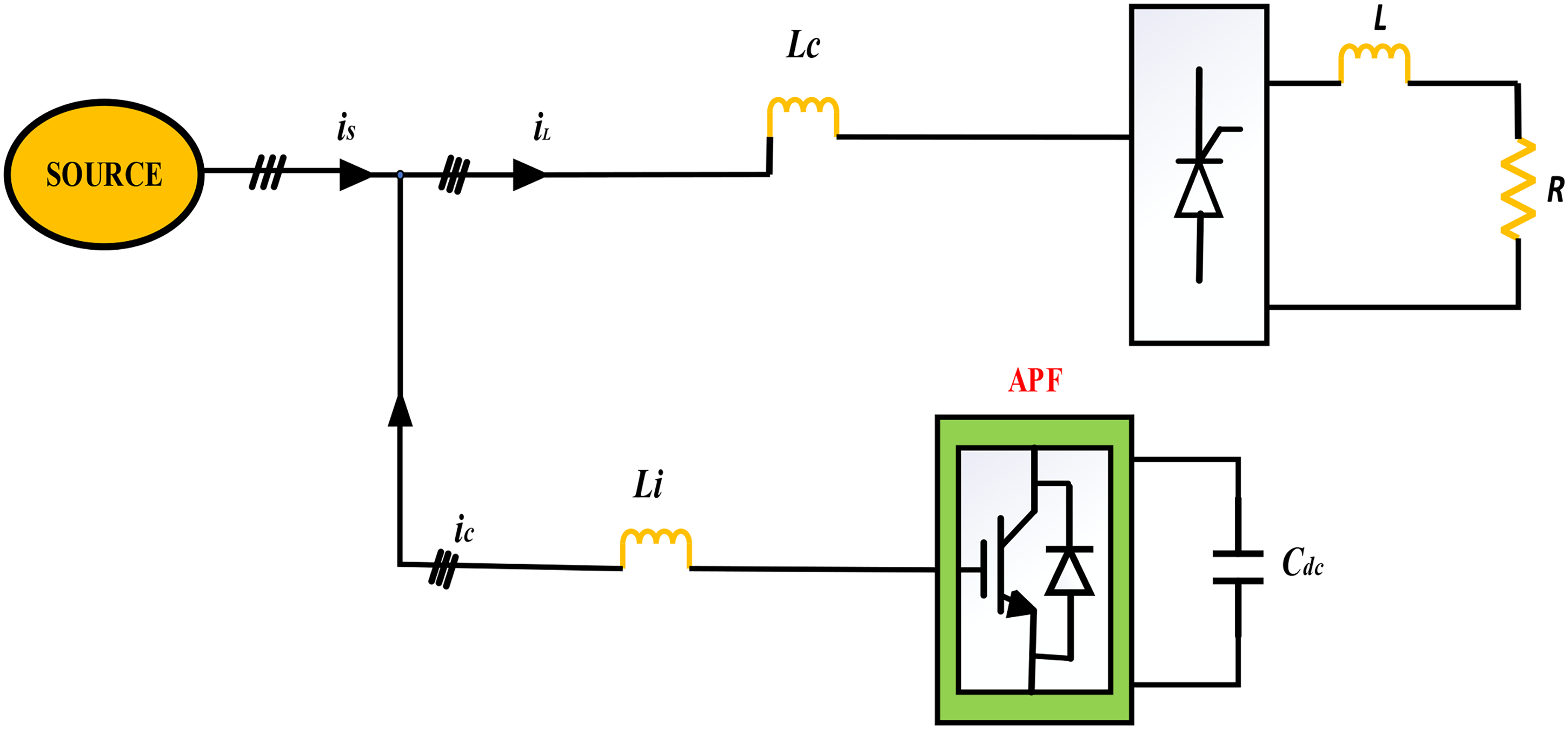
Shunt active power filter (SAPF) structure.
We get the utility voltage from the following equation:

Equation (2) provides the instantaneous value of source currents at the PCC.

Equation (3) represents the combination of the elementary and harmonic components that make up the

The power delivered by the load can be computed as per the following equations:


The source current provided by the SAPF after compensation can be given by the following equation:

SAPF control scheme
The control circuits involved with the SAPF are designed in such a way that their coordinated actions inject a current to compensate for the harmonics present, thereby enhancing the performance of the system (Patnaik and Panda, 2023). As mentioned earlier, the present work focuses on the performance of SAPF under the various combinations of control methods used for RCG, DC-link voltage control, and switching pulse generation. Hence, firstly, the outdated control tactics for RCG are detailed in this section. Thereafter, a fuzzy and PI controller-based strategy for
Reference current generation (RCG)
Control mechanisms for producing compensation currents can be implemented in either the frequency or time domain (Amini et al., 2023). Fourier analysis of the current signals is the control method for obtaining compensating current under the frequency domain approach. However, this approach requires complex mathematical computations, which might result in a longer turnaround time. However, the time domain approach is easier to use and has a simpler mathematical foundation. The two commonly utilized, simple, and easy-to-implement fundamental techniques, the SRF method and the MSRF method, are the foundation for the control strategy realization in this work. The following subsections provide a brief discussion of each of these topics.
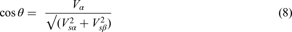
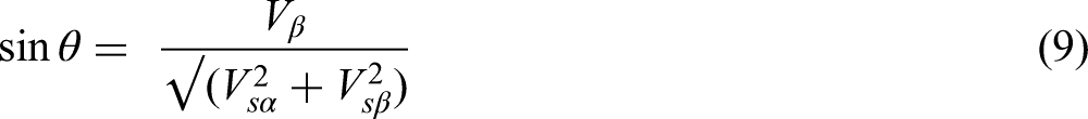
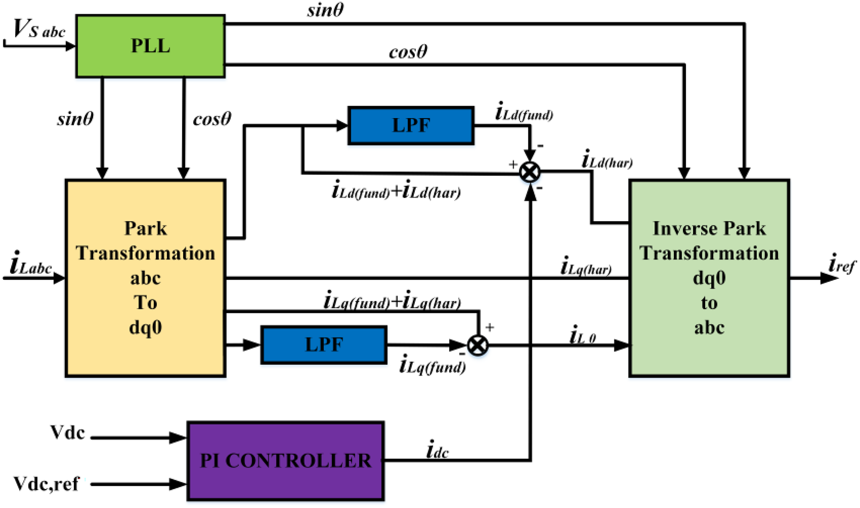
(a) SRF technique: Real-time SAPF control is achieved using the SRF theory-based control technique, which operates in both steady-state and transient modes (Belkhier and Oubelaid, 2024). As determined, the load's current draw is Harmonic reduction, power factor correction, and wattless power compensation are the uses of current components on the d-axis. The signals have been synchronized at a point by using a PLL called a common coupling point (PCC). A PLL is needed to obtain the phase information of periodic and physical control (Zorig et al., 2024). To obtain the DC elements of (b) MSRF method: MSRF uses a generating strategy of a unit vector to achieve synchronization, as the SRF methodology uses a PLL to achieve synchronization (Gude et al., 2023). MSRF design can be described by using the schematic diagram in Figure 3. Here,
Synchronous reference frame (SRF) method block diagram.
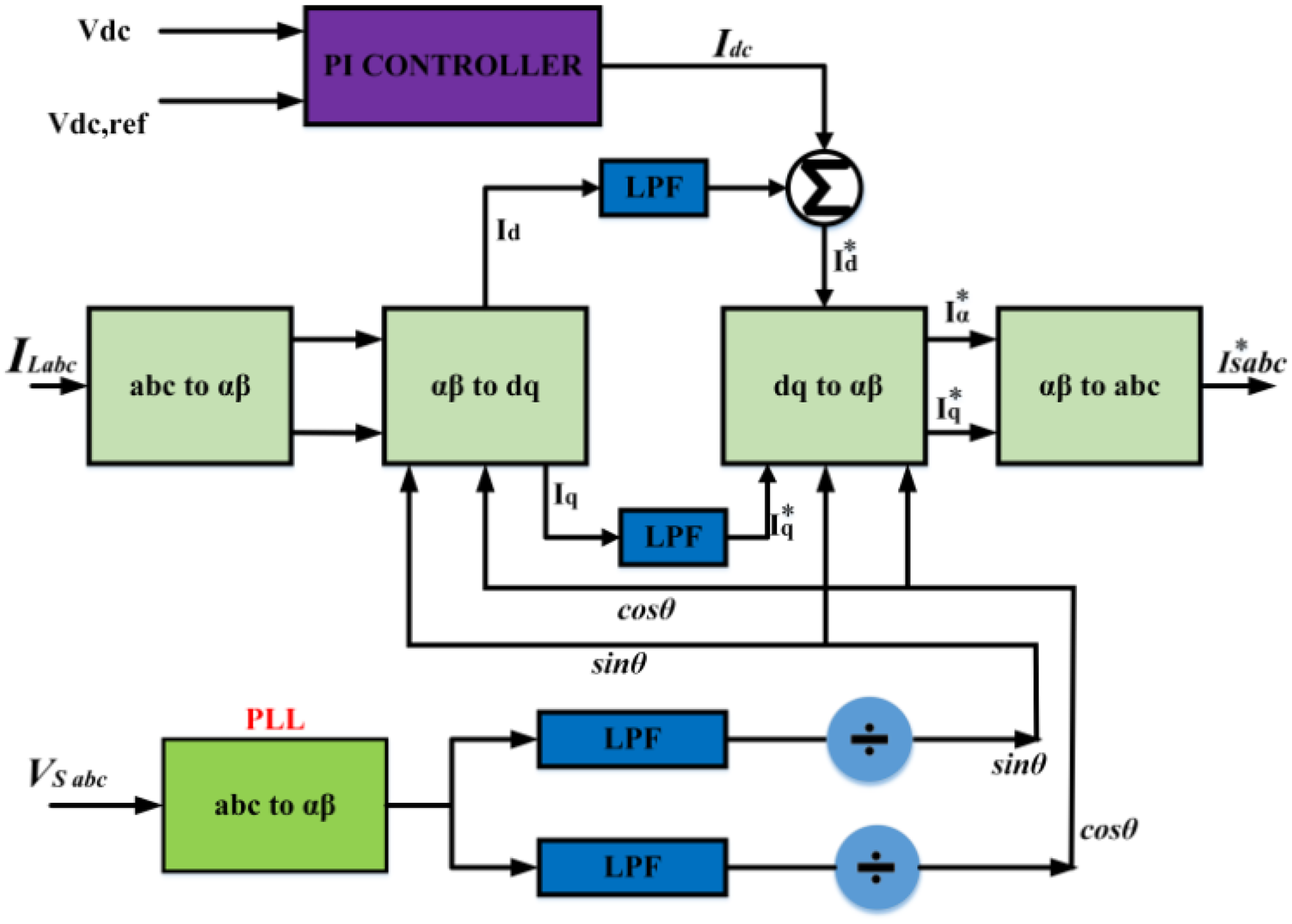
Modified synchronous reference frame (MSRF) design.
To extract the d–q axis currents (
Control technique for DC-link voltage
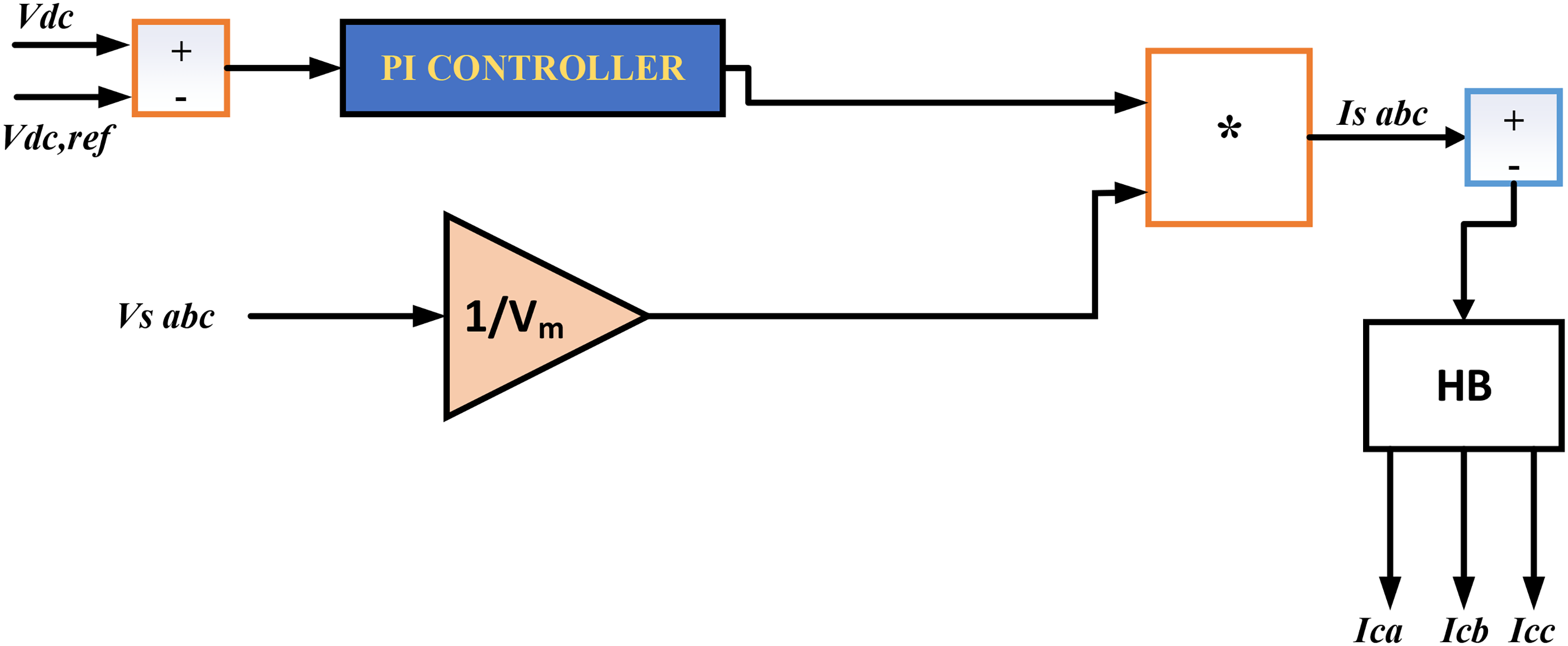
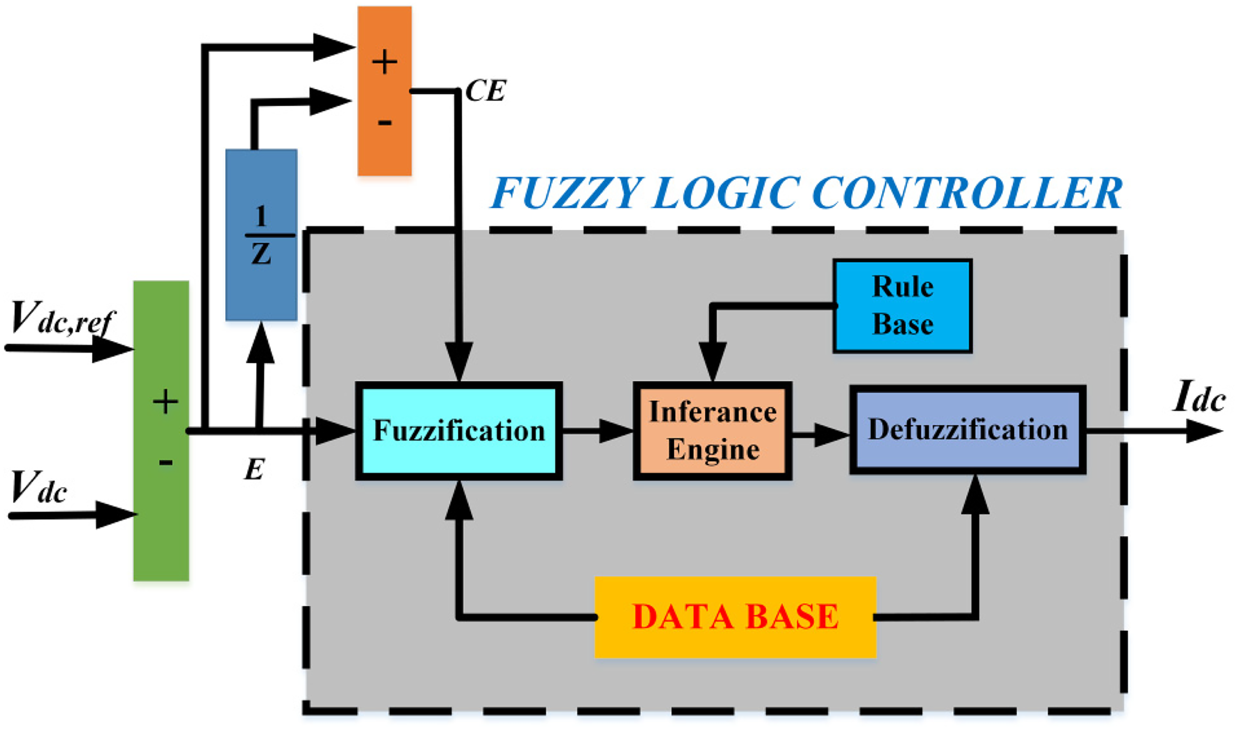
Because (a) PI (b) Fuzzy logic controller (FLC): Zadeh first presented FLC in 1965, and operational features can be described using fuzzy logic theory (Hosseini et al., 2024). The transitions between association and non-association functions are developed in fuzzy set theory. As a result, the borders or limitations of fuzzy sets might be ill-defined and unclear, which makes them helpful for designing approximate systems. In a closed loop, the observed capacitor voltage of the DC-bus is compared with the required value of reference voltage to carry out the FLC algorithm for a SAPF (Amini et al., 2023). A low-pass filter processes this calculated error signal Fuzzification: Fuzzification is the process of using language variables in place of mathematical variables in logic (Liu et al., 2024). The inaccuracy between the reference signal and the output signal in a control system can be classified as PH, PM, NL, ZE, PL, NH, or NM. Fuzzification procedures change genuine numerical variables into fuzzy numbers, which are linguistic variables. Rule elevator: The control gains of conventional controllers, such as PID and PI, are combinations of numerical values. Linguistic variables are used by the fuzzy logic controller in place of numerical ones. To evaluate fuzzy set rules, three fundamental fuzzy logic operations are needed: AND (∩), OR (∥), and NOT (−). It is defined as AND for intersection, OR for union, and NOT for complement functions, respectively. Defuzzification: The required output in language variables is generated by the fuzzy logic rules in real-time in response to demands (Han, 2024). It is necessary to convert the language variables to clear numerical values. This strategy's choice strikes a balance between computational effort and precision. Data and rule base: The triangle membership value definition, which is used by the fuzzifier and defuzzifier, is kept in the database. The language control rules that the rule evaluator (decision-making logic) uses are stored in the rule base. This suggested controller makes use of the 49 rules, as listed in Table 1. The peak reference current

Schematic diagram of voltage control across the DC link.
Fuzzy controller design.
Rule for the FLC method.
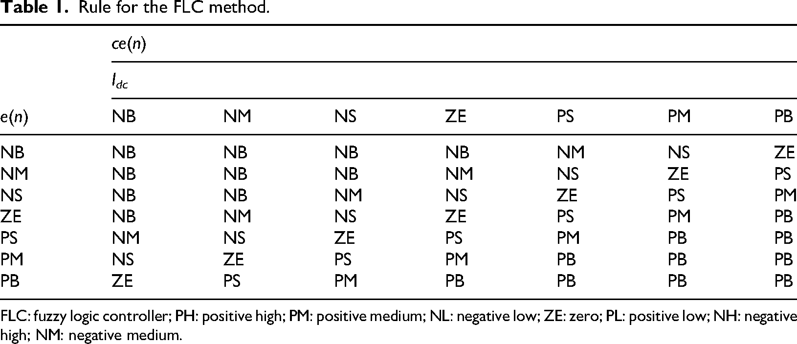
FLC: fuzzy logic controller; PH: positive high; PM: positive medium; NL: negative low; ZE: zero; PL: positive low; NH: negative high; NM: negative medium.
Switching pulse generation technique
Numerous pulse generation approaches, including space vector PWM, sinusoidal PWM, sinusoidal PWM with instantaneous current control, HCC-based PWM, selective harmonic elimination-based PWM, and others, are accessible in the literature.
Hysteresis band current control (HCC): It is a controller that makes the computed reference current Adaptive hysteresis band current control (AHCC): The present study proposes AHCC as a solution to the fixed-band HCC's shortcomings (Hamouda et al., 2019). By constructing an instantaneous hysteresis bandwidth based on voltage and current variation for compensation, AHCC builds smooth switching speeds and significantly fixes frequency switching. Equation (11) presents the correlation between the HB and fs based on the system topology, is shown in Figure 7. The switching pattern in this method is determined by the rising and falling currents within the HB. The minute the current error exceeds the top boundary of HB in this system, the bottom adjustment becomes active. When the incorrect current surpasses HB's lower limit, the higher switch is activated. The definite source current is therefore limited to following the reference current within the HB:

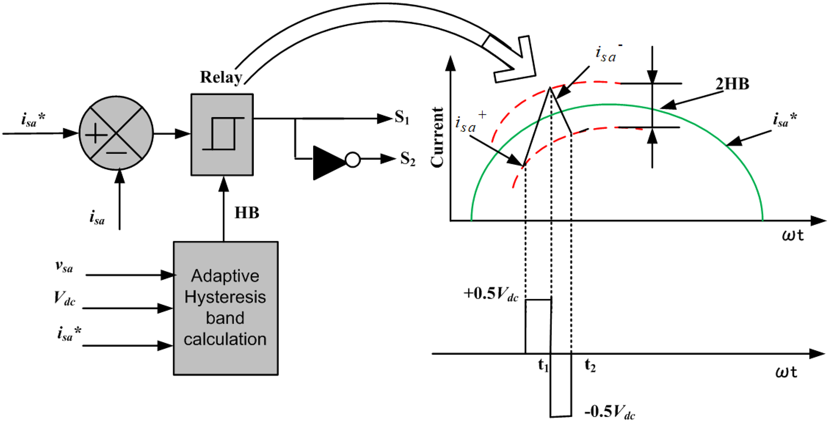
Model layout of the hysteresis current controller (HCC) scheme.
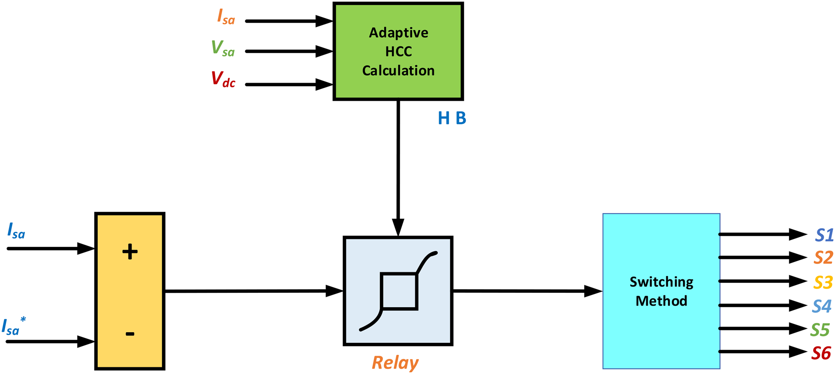
Schematic diagram of the adaptive hysteresis current controller (AHCC) scheme.
Solar PV system
A system that uses photovoltaic cells generates electricity from solar radiation using one or more solar panels. It is composed of several parts, such as the photovoltaic modules, mountings, and connections (both mechanical and electrical), and devices for controlling and/or adjusting the electrical output (Lucchi, 2024).
PV array
As shown in Figure 8, the nonlinear V–I characteristics of PV cells vary with temperature and solar radiation. For this reason, it is crucial to monitor the array's maximum power output. An MPPT-based algorithm is used by the author to regulate the duty cycle of a step-up converter so that most power can be extracted. Power from the PV array is channeled into a step-up converter. The SAPF's DC bus is where the step-up converter's output is attached. The step-up converter gives an increased output voltage of 700 V, whereas the PV array produces an output voltage of 274.4 V. The diode current (


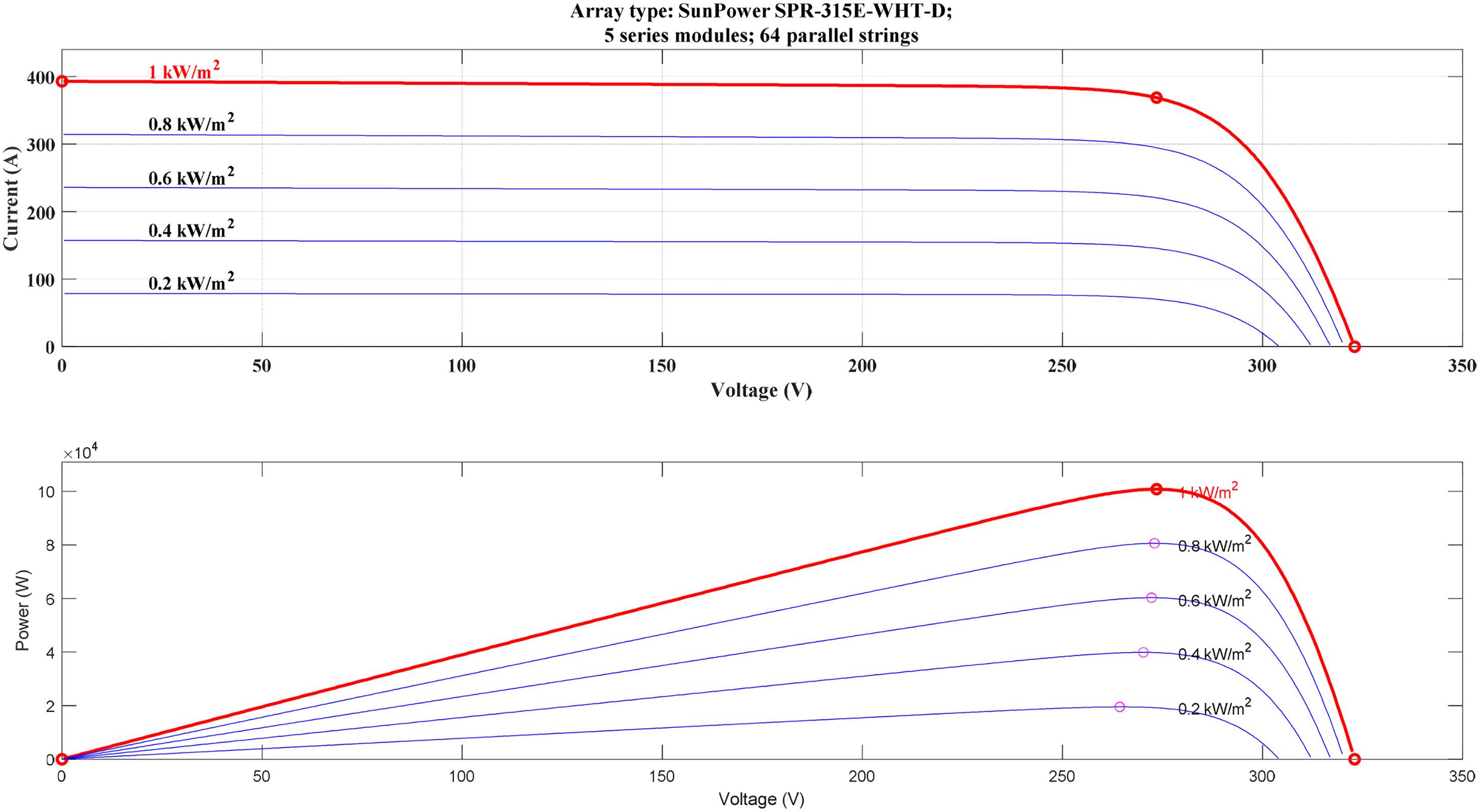
V–I and P–V characteristics of photovoltaic (PV) cells.
Control of step-up converter to achieve MPPT
An MPPT algorithm is used to operate a step-up converter. Power and voltage variations are the proposed MPPT algorithm's inputs, while duty cycle variation is its output. This algorithm produces an appropriate duty cycle that matches MPP. In this work, the MPPT algorithm is used to track MPP. This technique's primary benefit is that it will seek MPP regardless of the surrounding conditions. Every boost has its own MPPT in charge. A 750 V DC bus output is associated with the output of the step-up converter (Yadav et al., 2024). Figure 9 shows the SPV with a boost converter and MPPT.
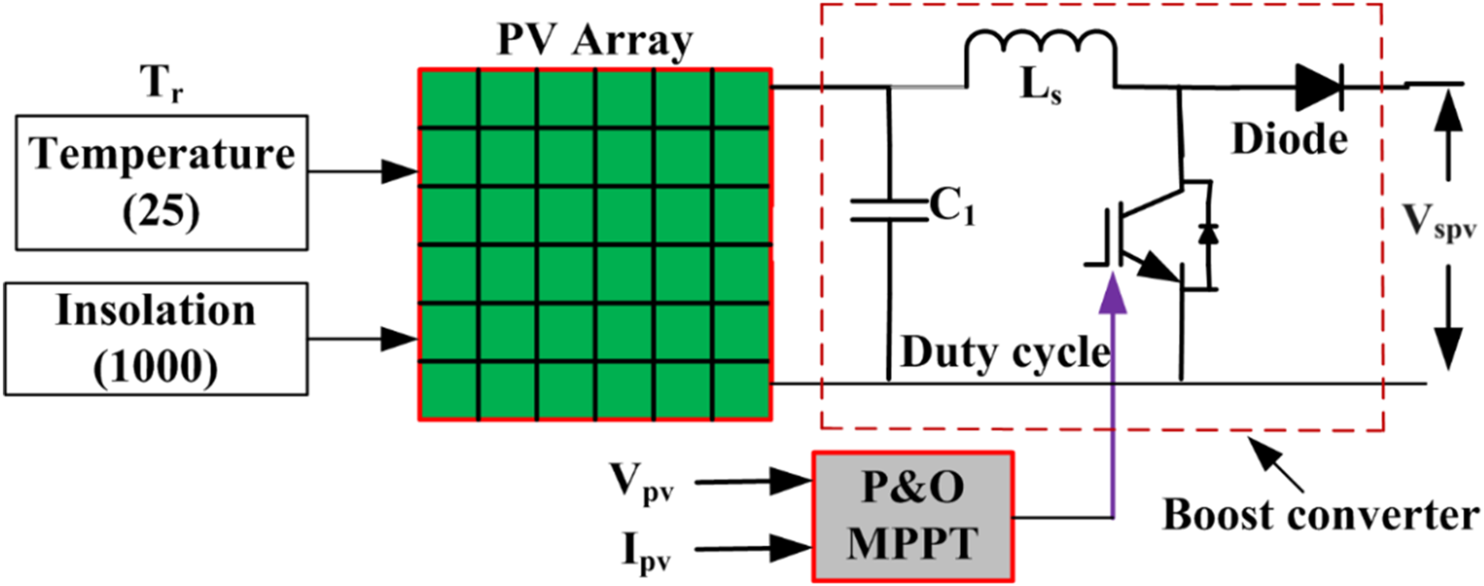
SPV with step-up converter and MPPT.
The step-up converter's construction
The step-up converter is required to employ the MPPT algorithm and supply solar PV electricity to the common DC link. Equation (15) is used to construct the step-up converter inductor.
The voltage associated with the PV array is
Selection of DC-link reference voltage
The minimum voltage 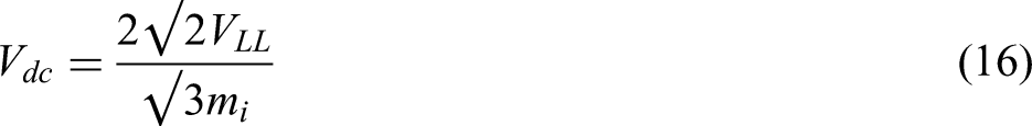
Designing an intermediate circuit capacitor (DC link)
The value of capacitors attached to the DC link, that is,
The following formula is used by the capacitor attached to the DC link to calculate the variance in stored energy, as given in the following equation:
Choosing the inductance of the filter
The compensating current of the SAPF includes the reactive and harmonic parts that make up the load current. Harmonic currents of the load ought to be able to enter the PCC through the inductor. Additionally, it will prevent high switching frequency harmonic currents from entering the PCC as a result of voltage source inverter (VSI) switching, as shown by the relationship below; that value may be computed as follows: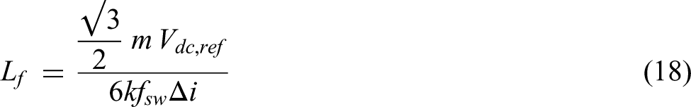
Results and discussion
In Figure 10, the proposed configuration is shown below. The PV module and step-up converter are the system's main components. The performance of SAPF with and without SPV on the DC-link side is examined in this section under various source and load-changing scenarios. A SAPF is in addition to the observed control algorithms (i.e. MSRF methods) for RCG to improve harmonic filtering. In addition to the aforementioned, the current FLC techniques and AHCC scheme are used to generate PWM pulses and regulate them, respectively. The combinations of schemes using the traditional MSRF approach (for RCG) in this study, FLC controller (for control), and AHCC (for PWM signal generation) used for producing compensating current are referred to as MSRF-FLC-AHCC techniques without SPV on the DC-link side. On the other hand, the combination MSRF-FLC-AHCC technique is used with SPV on the DC-link side.
Proposed SPV-based SAPF.
Under various controller actions and loading situations, the performance studies of the system under study are examined both with and without SAPF and are referred to as distinct scenarios to consider. The results of interest under each scenario are highlighted in bold in the respective table.
Scenario 1: Performance analysis without SAPF and with SAPF employing the MSRF-FLC-AHCC scheme under normal source conditions. Scenario 2: Performance analysis without SAPF and with SAPF employing MSRF-FLC-AHCC scheme under distorted source conditions. Scenario 3: Performance analysis with SAPF employing MSRF-FLC-AHCC scheme under distorted source condition, implementing SPV across the DC-link side.
Performance study under Scenario 1
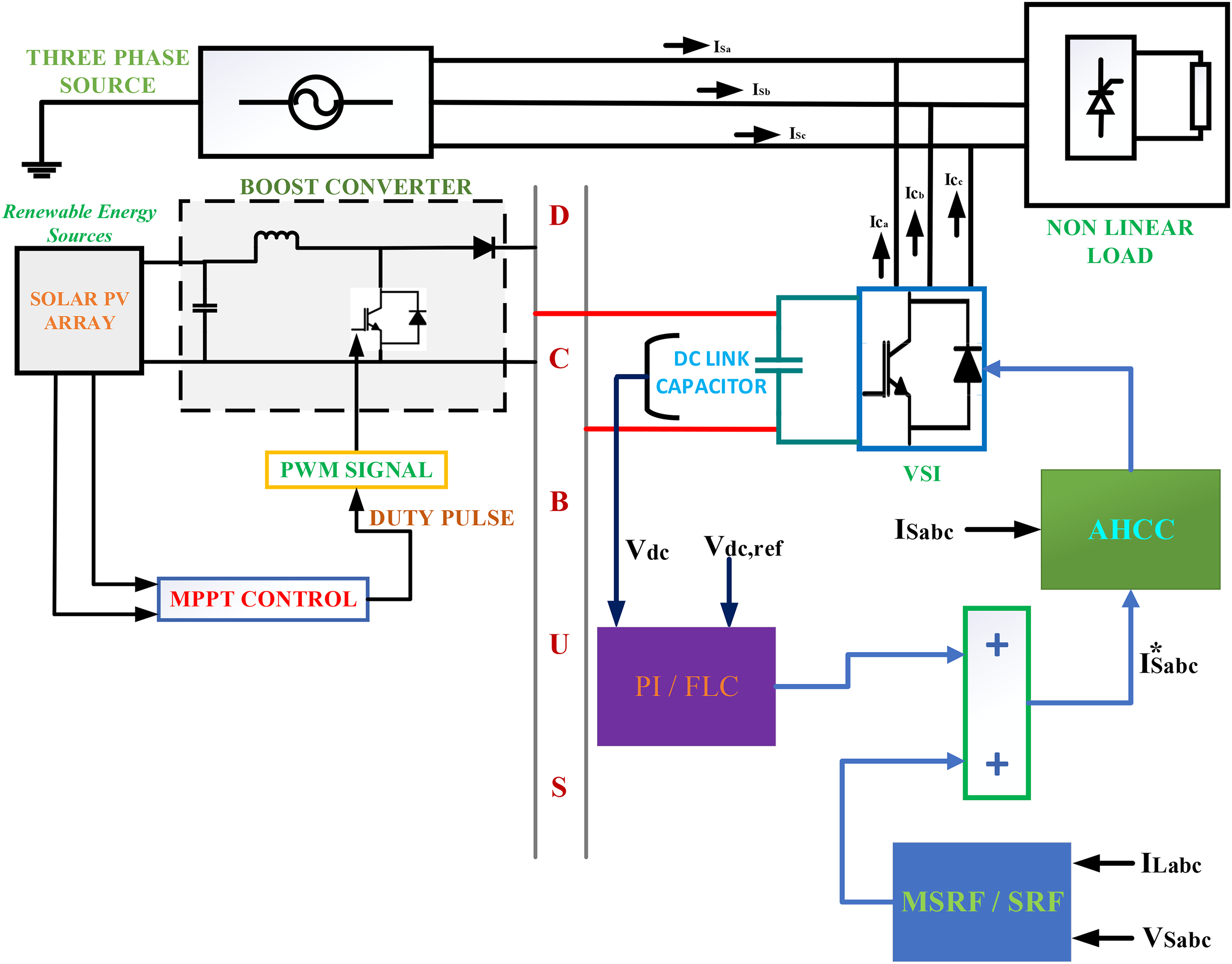
First, with a diode bridge-type nonlinear inductive load, we check the THD of the source current (Is) without SAPF, assuming a normal source voltage. The source voltage (Vs) waveform, the waveform, and THD under this condition are offered in Figure 11(a) to (c), respectively.
Profiles attained during RL-load without SAPF normal source: (a)
It is observed from Figure 11(c) that the wave shape THD of 26.74% for the RL-load. However, in the case of RC-type nonlinear load as viewed from Figure 12(c), the THD of the waveform is very large at 30.05%. Figure 12(a) and (b) shows the corresponding Vs and Is waveforms, respectively.
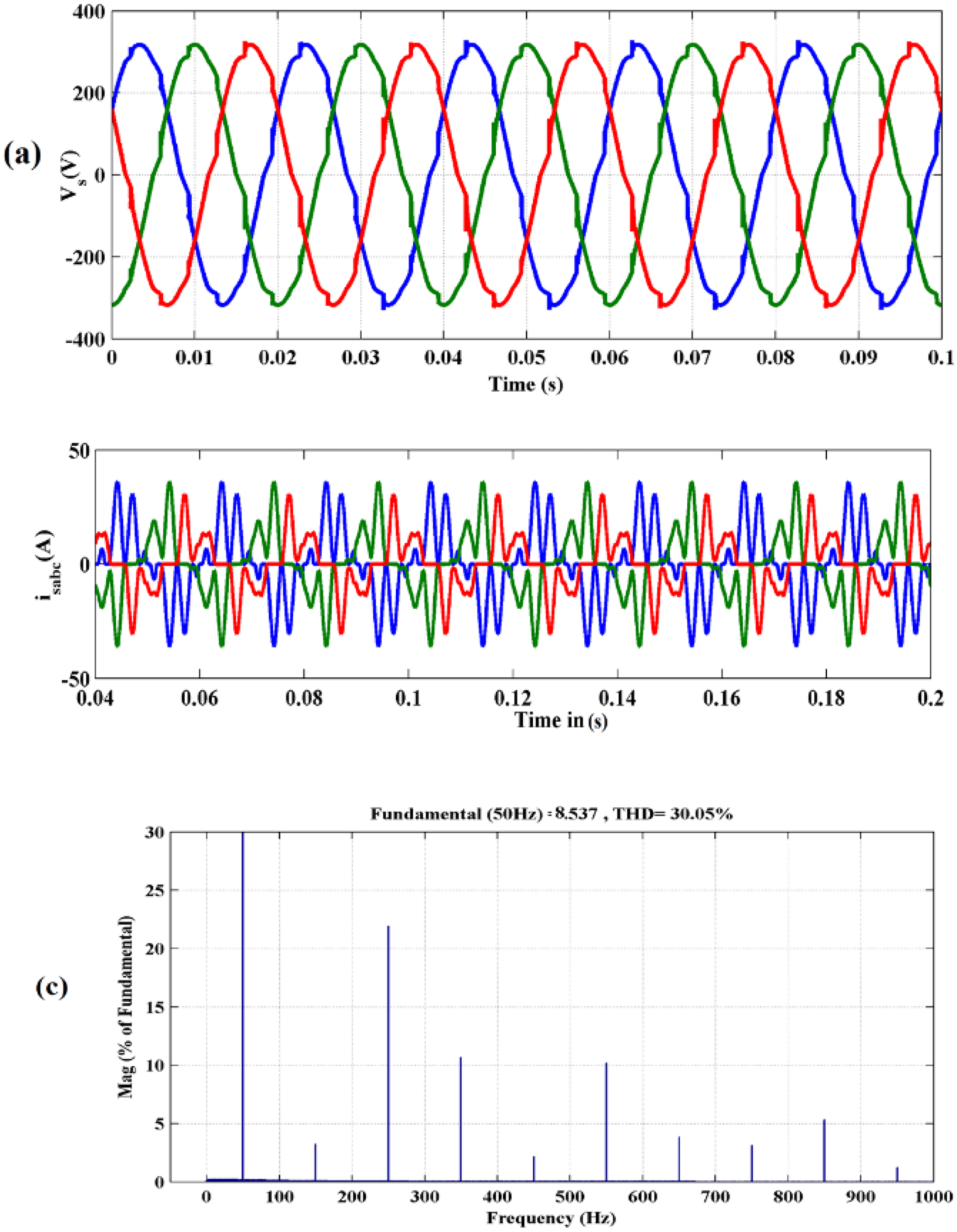
Profiles attained during RC-load without SAPF normal source: (a)
To test the competency of the proposed controller, the SAPF will generate the using MSRF-FLC-AHCC techniques under RL and RC load conditions. This, as given in Figures 13(a) and 14(a), reduces the THD of and improves its waveform quality by injecting it at PCC. The waveform and its compensated THD current are illustrated in Figure 13(b) and (c) for the case of RL-load and Figure 14(b) and (c) for RC-load, respectively. It is observed from Figure 13(c) that the THD value of reduced to 2.35% (Liu et al., 2024; Patel et al., 2022) in the RL-load. Similarly, for the case of RC-load, the THD reduces to 2.15% (Liu et al., 2024; Patel et al., 2022) as presented in Figure 14(c).
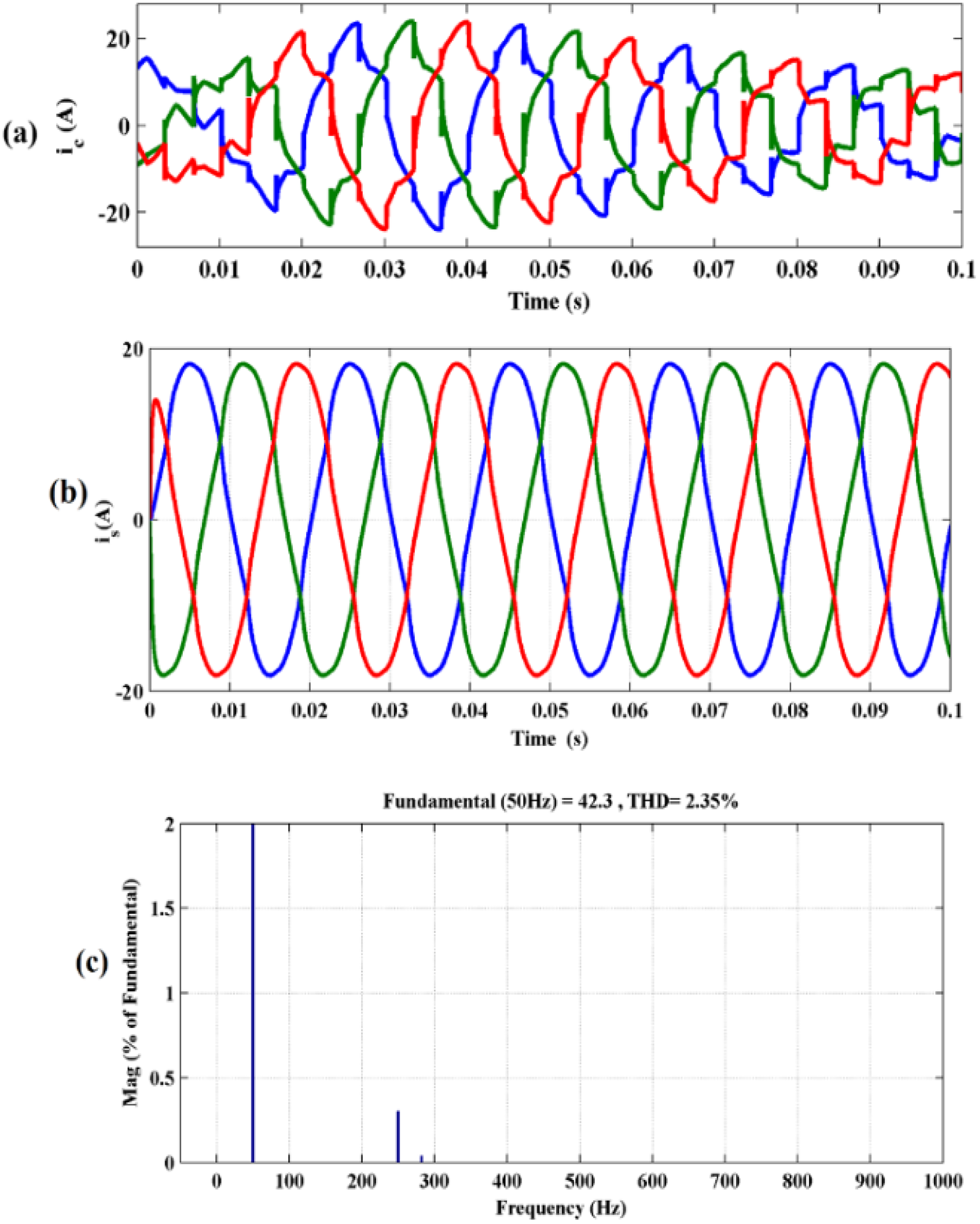
Profiles attained with RL-load with SAPF normal source: (a)
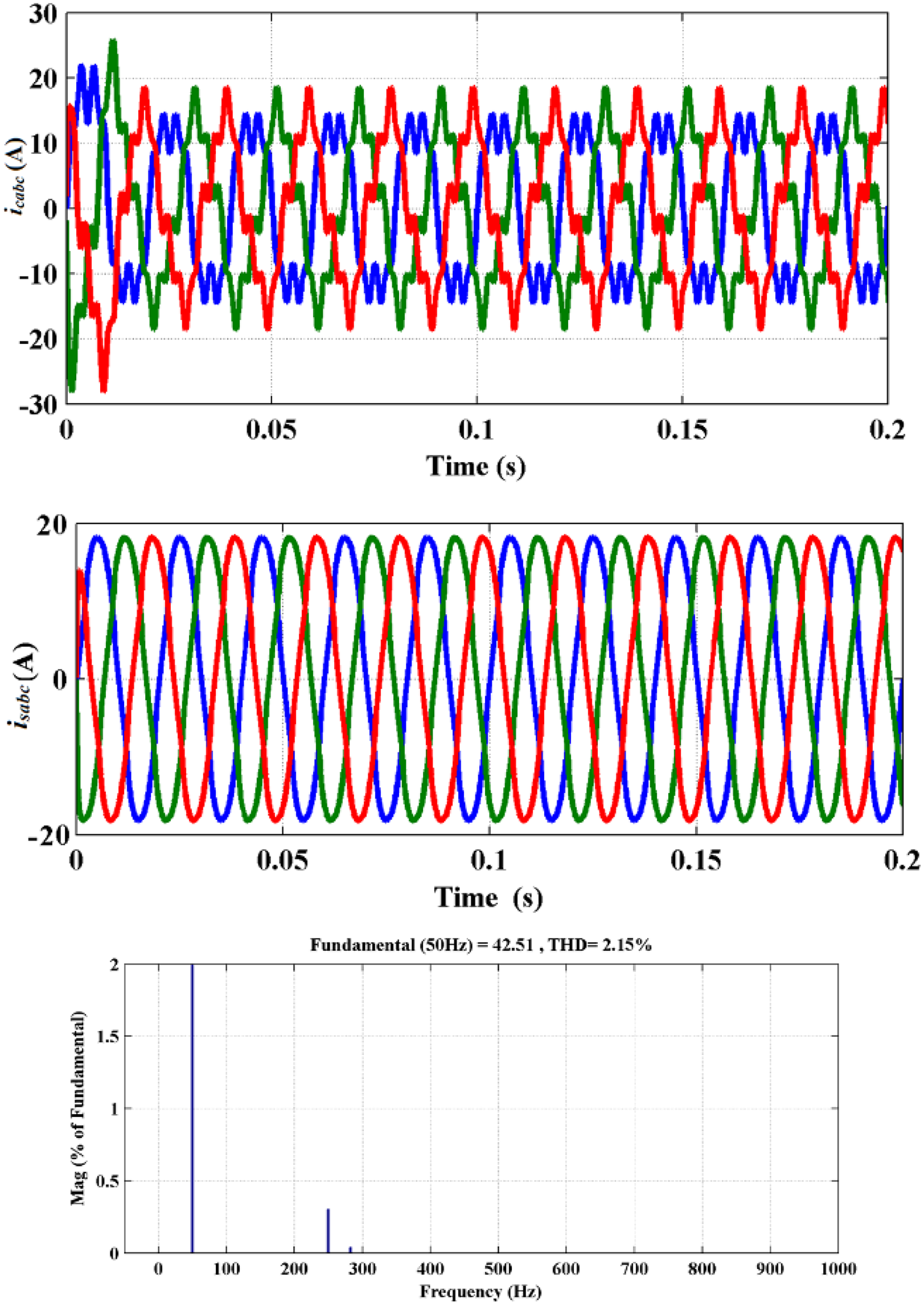
Profiles attained by RC-load with SAPF normal source: (a)
Performance study under Scenario 2
In this instance, the THD has also been checked under distorted source conditions, considering both the RL and RC loads. The distorted source wave shape, wave shape, and THD under this condition are presented in Figure 15(a) to (c) and Figure 16(a) to (c), considering without SAPF for R-L and R-C loads, respectively. It is viewed from Figure 15(c), that the THD of Is the waveform is very large, 38.15% for R-L load and 40.05% for R-C load, as presented in Figure 16(c). To test the performance of the proposed controller under distorted source conditions, the SAPF will be generated using MSRF-FLC-AHCC techniques under RL- and RC-load. This, as given in Figures 17(a) and 18(a), reduces the THD of and improves its waveform quality by injecting it at PCC. The waveform and its compensated THD current are presented in Figure 17(b) and (c) for the case of RL-load and Figure 18(b) and (c) for RC-load, respectively. It is observed from Figure 17(c) that the THD value reduces to 3.42% (Liu et al., 2024; Patel et al., 2022) in the RL-load. Similarly, for the case of RC-load, the THD reduces to 3.12% (Liu et al., 2024; Patel et al., 2022), as presented in Figure 18(c). It is revealed from the results that under distorted source conditions, the THD mitigation of the SAPF is not up to the mark. Hence, the THD may be further reduced by controlling the DC-link voltage of the SAPF by using an SPV system across the DC-link side of the SAPF.
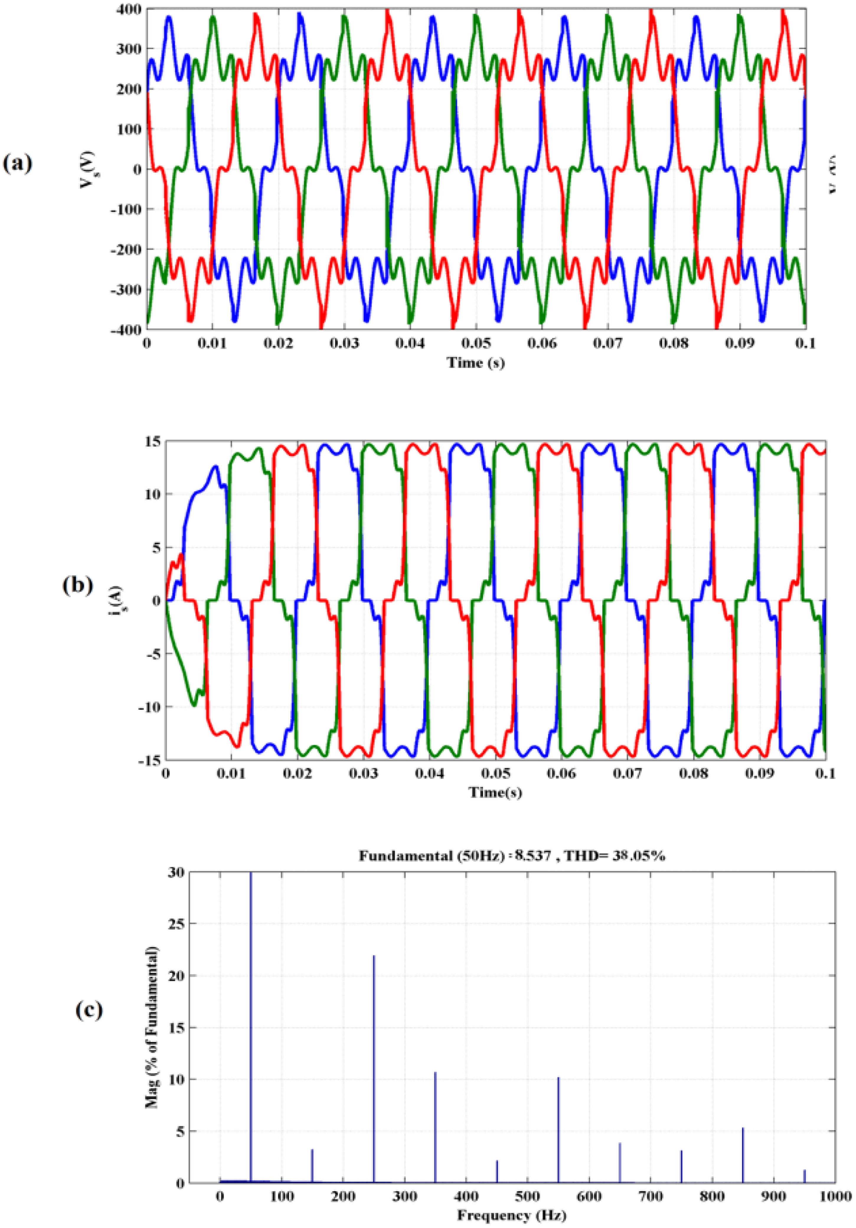
Profiles attained by RL-load without SAPF distorted source: (a)
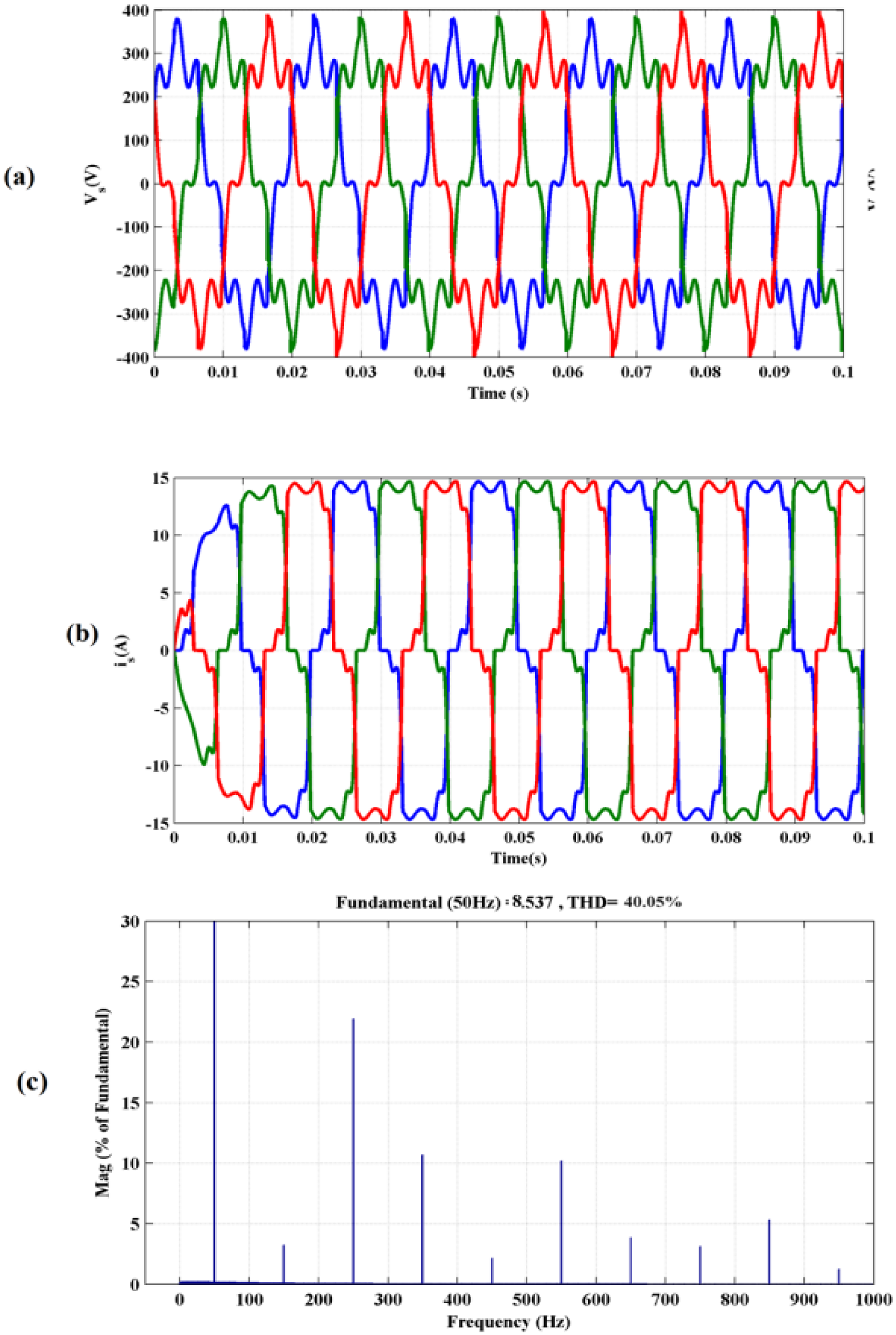
Profiles attained by RC-load without SAPF distorted source: (a)
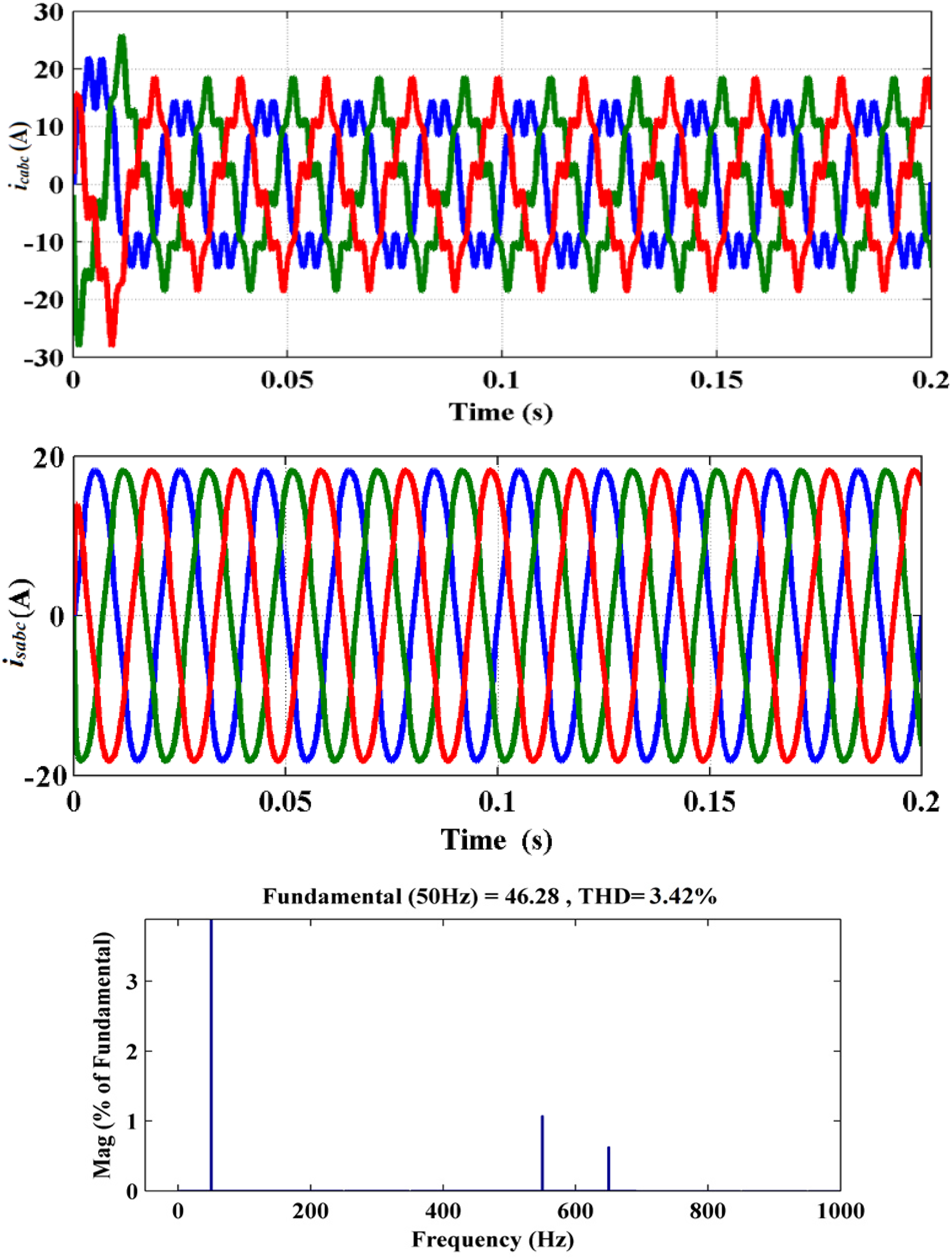
Profiles attained by RL-load with SAPF distorted source: (a)
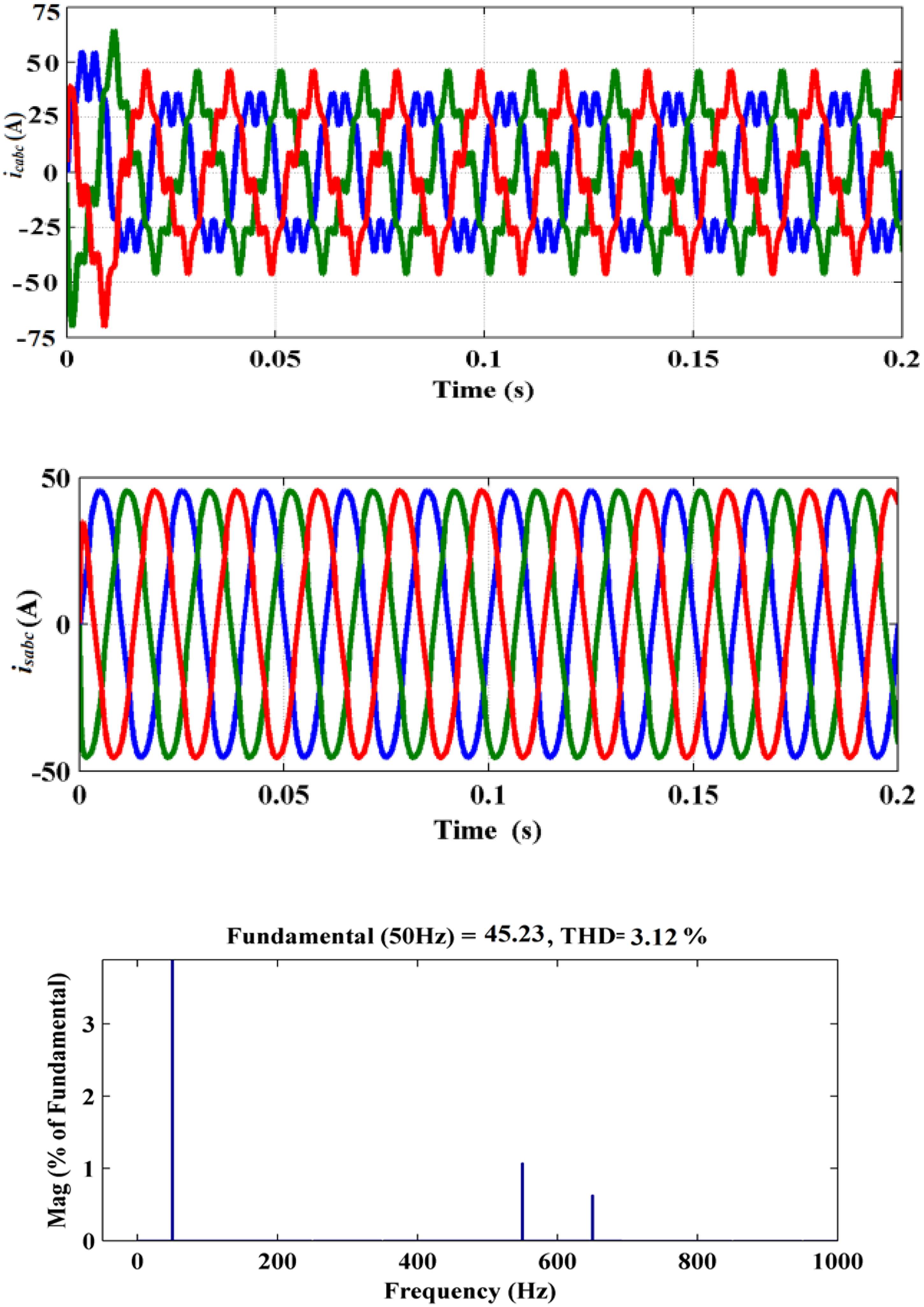
Profiles attained by RC-load with SAPF distorted source: (a)
Performance study under Scenario 3
In this state, the act of the SAPF has been analyzed by integrating SPV across the DC-link side of the SAPF under distorted source conditions. The performance is evaluated considering two parameters, that is, (1) THD comparison and (2) DC-link voltage regulation comparison.
THD analysis
The profile produced by the MSRF-FLC-AHCC-based scheme is revealed in Figure 19(a) for both R-L and R-C-type loads. Figure 19(b) illustrates the waveform obtained after compensation for each type of load. The THD inquiry reports (with SAPF) for individual loads are accessible in Figure 19(c). The results demonstrate that the signal is virtually sinusoidal, exhibiting low THD values of 1.20% and 1.15% obtained for R-L- and R-C-type nonlinear loads, respectively, in the presence of MSRF-FLC-AHCC-based technique under normal source conditions and THD values of 2.22% and 2.15% obtained for R-L- and R-C-type loads, respectively, under distorted source conditions. Figure 20(a) to (c) represents the corresponding waveforms under distorted source conditions. The THD comparison result is presented in Table 2. It is visible from Table 2 that the proposed SPV-based SAPF with MSRF-FLC-AHCC control algorithm gives the best THD result as compared to others, both under normal and distorted source conditions.
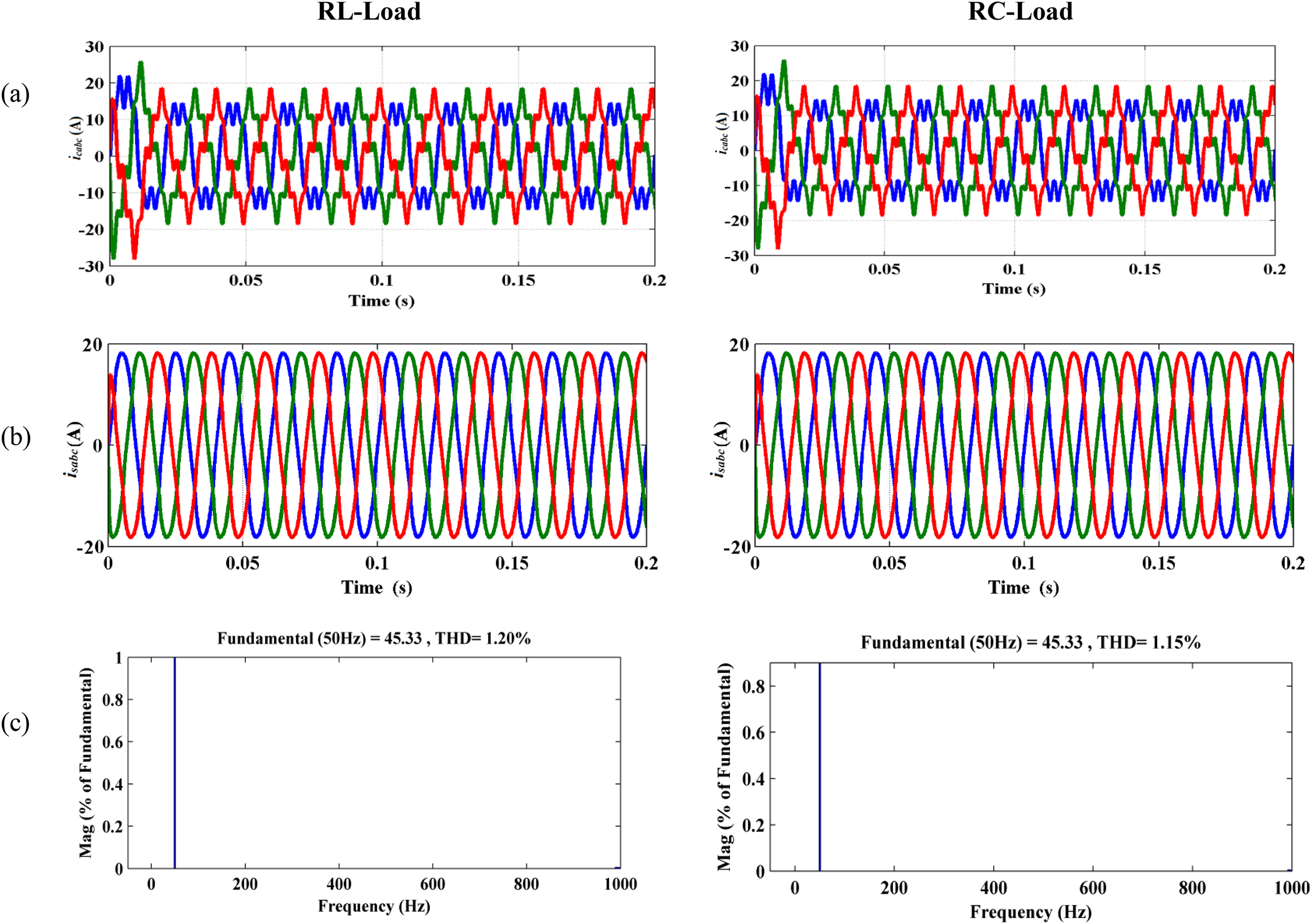
Profiles attained with SPV-based SAPF considering normal source: (a)
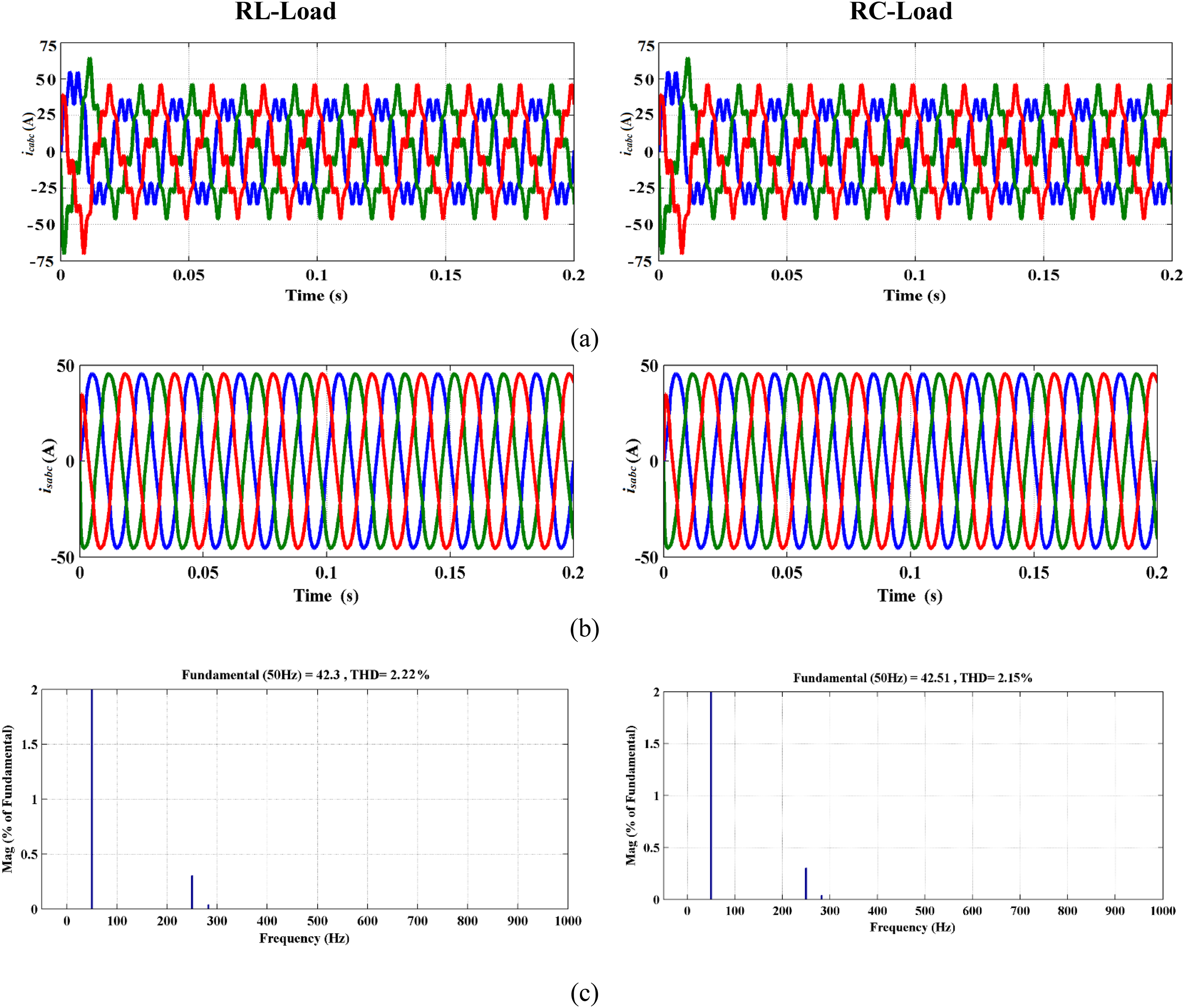
Profiles obtained under SPV-based SAPF considering distorted source (a)
THD comparison of
R-L: resistor-inductor; R-C: resistor-capacitor; THD: total harmonic distortion; SPV: solar photovoltaic; SAPF: shunt active power filter.
regulation
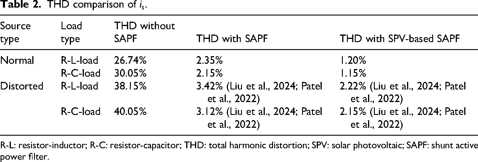
In this case, the act of the anticipated SPV-based SAPF with MSRF-FLC-AHCC control strategy is compared without SPV-based SAPF in regulating 
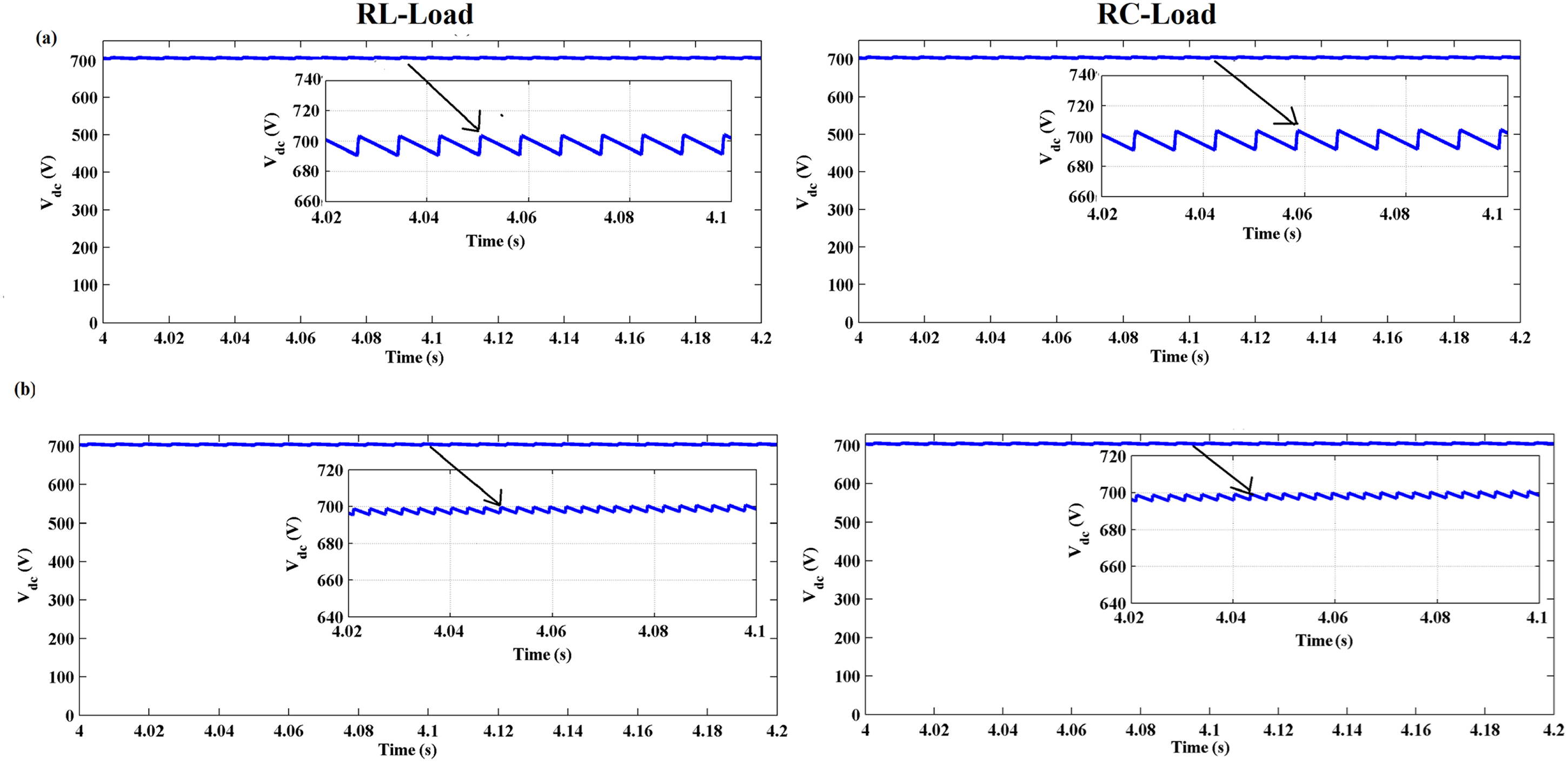
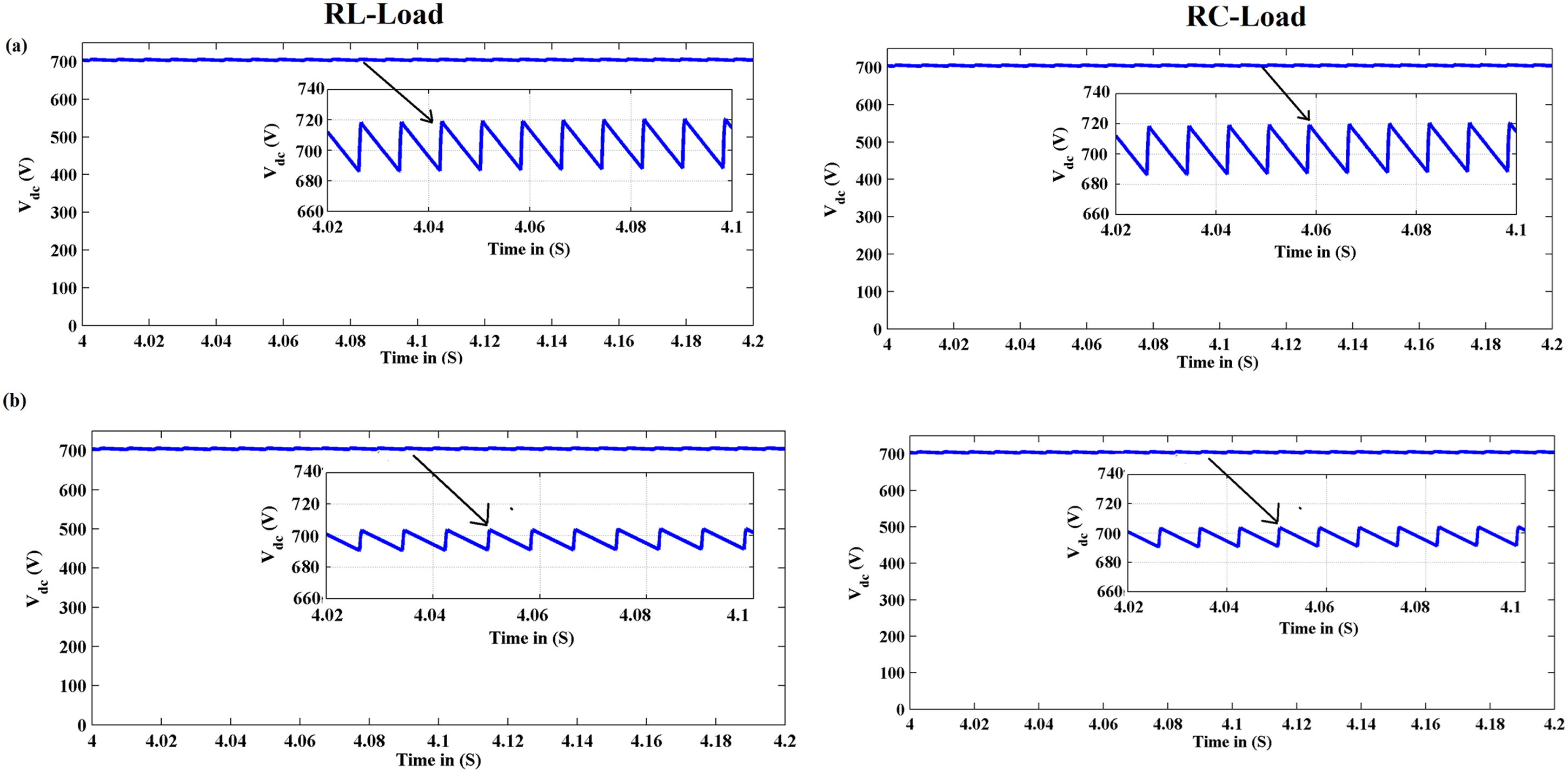
It is evident from Figure 21 and Table 3 that under normal source conditions, the maximum deviation of 18 and 20 V in the wave shape is perceived under the MSRF-FLC-AHCC approach without SPV-based SAPF for R-L- and R-C-load types, respectively. Also, the %ACC of 97.50% and 97.20% are found for R-L- and R-C-load types, respectively. However, the proposed SPV-based SAPF with MSRF-FLC-AHCC control topology offers the least deviation of 4 and 3 V with further improvement in %ACC to 99.42% and 99.57% for R-L- and R-C-type nonlinear loads, respectively. Similarly, under distorted source conditions, the maximum deviation of 24 and 28 V in the wave shape is observed under the MSRF-FLC-AHCC approach without SPV-based SAPF for RL- and RC-load types, respectively, as given in Figure 22. Also, the %ACC of 96.54% and 96.00% are found for RL- and RC-load types, respectively. However, the proposed SPV-based SAPF with MSRF-FLC-AHCC control topology offers the least deviation of 6 and 7 V with further improvement in %ACC to 99.15% and 99% for RL- and RC-type nonlinear loads, respectively.
Comparison of
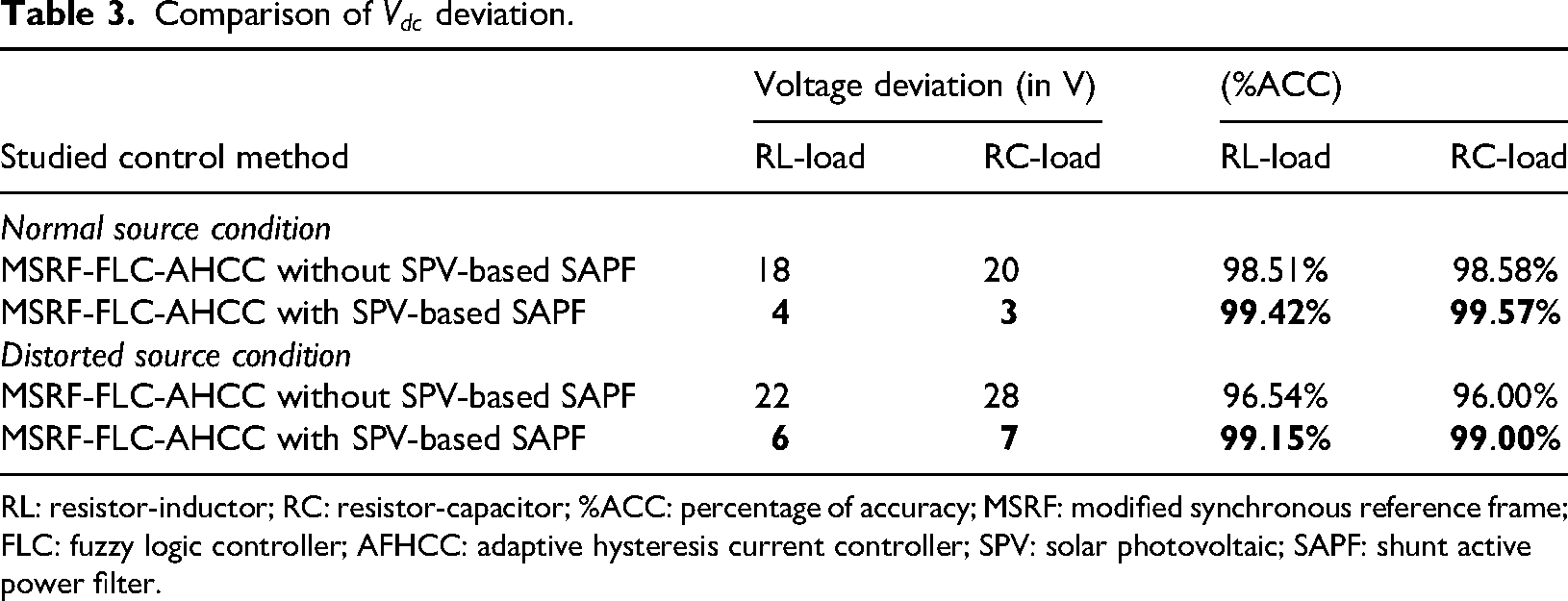
RL: resistor-inductor; RC: resistor-capacitor; %ACC: percentage of accuracy; MSRF: modified synchronous reference frame; FLC: fuzzy logic controller; AFHCC: adaptive hysteresis current controller; SPV: solar photovoltaic; SAPF: shunt active power filter.
Conclusion
This study investigates the system's harmonic mitigation under the influence of the suggested MSRF-FLC-AHCC-based realized SAPF, taking into account both SPV-based SAPF and without SPV-SAPF. In addition, the optimal combination of RCG, regulation, and switching pulse generation mechanisms for VSI has been identified and contrasted. By deploying the SPV system across the DC-link side of the SAPF, the suggested MSRF-FLC-AHCC control technique beats its counterparts in terms of reducing deviation and settling time in the profile and mitigating harmonics, according to the results of sequences of simulation-based experimentations. In light of R-L- and R-C-type nonlinear loads, the comparative numerical findings show that the suggested SPV-based SAPF performance lessens the source current harmonics to 1.20% and 1.15% under normal source conditions, and 2.22% and 2.15% under distorted source conditions, respectively. The best outcomes in terms of mitigating harmonics have thus been provided by the suggested control structure. Furthermore, we intend to integrate additional renewable energy sources, such as wind and fuel cells, to analyze the system's behavior under varying operating conditions. The limitations related to scalability and PV intermittency will also be addressed and discussed in future work to enhance the overall robustness and applicability of the proposed system. As the present work is entirely simulation-based, we acknowledge the importance of experimental validation to strengthen the practical relevance of the proposed control scheme. In our future research, we plan to extend this study by incorporating hardware-in-the-loop testing and small-scale experimental implementation to evaluate real-time performance.
Footnotes
Funding
The authors received no financial support for the research, authorship, and/or publication of this article.
Declaration of conflicting interests
The authors declared no potential conflicts of interest with respect to the research, authorship, and/or publication of this article.