
Abstract
Conventional solar air heaters often suffer from limited heat transfer efficiency due to suboptimal absorber plate designs and high irreversibility, constraining their applicability in thermal energy systems. Addressing this limitation, the present study develops and validates a comprehensive mathematical model—implemented in MATLAB—for a double-pass solar air heater equipped with a novel serrated absorber plate. The primary objective is to quantify the enhancements in both energy and exergy performance and to identify the governing design and operating parameters. The model incorporates detailed energy and exergy balance equations for all system components and shows strong agreement with previous experimental data. Parametric analysis reveals that increasing the gap between the glass cover and absorber plate results in an 11% increase in thermal efficiency and a 21% improvement in exergy efficiency. Additional findings highlight the positive influence of fin height, air mass flow rate, and solar irradiance on system performance, while acknowledging the tradeoff of increased pressure drop. Qualitatively, the serrated geometry enhances turbulence, boosts heat transfer, and lowers entropy generation relative to flat absorbers. These results have practical implications for designing cost-effective, high-performance solar air heaters suitable for drying, space heating, and renewable thermal applications, thereby contributing to sustainable energy system optimization.
Introduction
There are various kinds of solar heaters, like single-pass, double-pass, and multipass systems (Alayi and Ebazadeh, 2025; Ebazadeh et al., 2024). The effectiveness of solar heaters relies on factors such as the intensity of solar radiation and the thermal properties of the absorber plate (Haghmoradkhani et al., 2025; Rajhi et al., 2024). Scientists have come up with different methods to enhance the efficiency of air heaters, such as improving the heat transfer between the air and the absorber plate (Li et al., 2023; Zhu et al., 2025a, 2025b). One successful modification is using a serrated absorber plate design. The researchers (Duan et al., 2025; Niu et al., 2022; Zhu et al., 2025c) introduced a design for a flat-plate solar air heater that reduces entropy generation. A serrated absorber plate is an absorber surface featuring a repeating pattern of protrusions (“teeth”) and gaps along the airflow direction, typically in V-, trapezoidal-, or sawtooth-shaped profiles. This geometric modification increases surface area and disrupts the thermal boundary layer, thereby enhancing turbulence and convective heat transfer between the airflow and the plate. Compared with a flat absorber, serrated configurations generally yield higher thermal performance, albeit often at the cost of increased pressure drop.
Kurtbas and Durmuş (2004) studied the efficiency of five different types of air heaters with various flow patterns on the absorber plate. They found that increasing surface roughness leads to higher heat transfer and pressure drop. They also noted that as collector efficiency increases, exergy destruction within the system decreases, and there is a negative relationship between exergy destruction and heat transfer. Naphon (2005) conducted a numerical analysis of a two-pass solar air heater with longitudinal fins, developing a mathematical model based on energy conservation equations. He concluded that thermal efficiency improves with greater height and more fins. Karsli (2007) experimentally tested four different air heaters with varying angles and absorber plates, evaluating their first and second law efficiencies. The most efficient air heater had a finned absorber plate at a 75-degree tilt angle. Esen (2008) conducted experiments on a traditional two-way solar collector and four unique absorber plates, studying the exergy relationships of these collectors. He found that the collector with a flat absorber plate without barriers had the highest irreversibility and lowest efficiency. Oztop et al. (2013) analyzed the energy and exergy aspects of solar air heater systems, noting that more research has been done on energy analysis techniques compared to exergy analysis methods. Alim et al. (2013) studied entropy generation and pressure drop in a solar air heater using nanofluids, finding that copper oxide (CuO) nanofluid reduced entropy generation and increased heat transfer compared to water. Karim et al. (2014) compared a theoretical two-way toothed air heater with an experimental model.
Bahrehmand et al. (2015) studied the thermal behavior of two types of air heaters, single-wall and double-wall, using forced convection flow. They found that at high Reynolds numbers, the exergy efficiency of the double-walled glass air heater is negative. Abuşka and Şevik (2017) conducted an experimental analysis on a solar air heater with a flat plate and a serrated absorber plate, using copper and aluminum as absorbing materials. They concluded that the air heater with a copper serrated absorber plate performed the best. Ansari and Bazargan (2017) investigated the optimization of pressure drop and heat transfer in a serrated solar air heater, suggesting that serrations improve heat transfer but also increase pressure drop. They used the genetic algorithm method for optimization. Abuşka (2018) studied the thermal behavior of an absorber plate with conical teeth and compared it to a flat plate collector in a single-pass air heater system. Ural (2019) evaluated the energy and exergy performance of a flat plate air heater with a fabric absorber, noting that the fabric improved both energy and exergy performance but also increased pressure drop. Reddy et al. (2019) analyzed a solar air heater with a corrugated absorber plate and a specialized system, reporting peak thermal efficiency and second law efficiency of 37.22% and 11.58%, respectively.
Fudholi and Sopian (2019) discussed various aspects of flat plate solar air heaters in a review article. They provided details about the performance of these air heaters, specifically focusing on their energy and exergy efficiency. Their research showed that the thermal efficiency of indoor experiments ranged from 30% to 79%, while the exergy efficiency ranged from 8% to 61%. Raam Dheep and Sreekumar (2020) conducted an experimental study on a single-pass parallel flow solar air heater that used round blades in the air flow path to improve convection heat transfer. They conducted experiments using five different mass flow rates. The results showed that at lower flow rates, the temperature of the air coming out of the air heater increases.
Hatami et al. (2020) analyzed the energy and exergy of a solar dryer using a dynamic model. Their model considered factors like radiation absorbed by the collector, temperature changes along the collector, and other elements. The model closely matched the experimental results. Ma et al. (2020) studied the energy and exergy of a drying system that included an air-based thermal energy storage unit, Phase Change Materials, and a photovoltaic solar air heater. They used TRNSYS software to assess the system's efficiency and examined factors like heat and exergy distribution. They found that the photovoltaic solar air heater section of the system had higher exergy destruction.
Prakash and Kamatchi (2023) created a low-cost solar air heating collector featuring a natural convection step serrated fin plate integrated trough array. This system achieved a heat stagnation temperature exceeding 70°C, with an energy efficiency of 66.32%. The natural convection solar air heater demonstrated a high performance with a Nusselt number of approximately 7.11 for a Rayleigh number of around 441.5 × 10³. The cost per kilowatt-hour of annual useful energy was calculated to be $0.1041, with a maximum thermal performance factor of 1.4. This technology is applicable for drying agricultural products, ensuring moisture safety and extending shelf life. Singh et al. (2024) investigated the thermal performance of solar air heaters utilizing two distinct absorber plates across two different configurations. Their experiments were conducted under the summer climatic conditions of Moradabad City, India. The optimal daily average efficiency reached approximately 63% at a flow rate of 0.03 kg/s. The efficiency of a serrated plate-type solar air heater, which did not incorporate phase change material, was found to be about 23% greater than that of a conventional system, and approximately 19% higher than that of a conventional solar air heater that utilized phase change material. Farhan et al. (2021) conducted a theoretical study on a V-corrugated solar air heater with a twisted tape insert (TTI). They determined that the optimal number of channels for achieving maximum thermohydraulic efficiency was five. The thermal and thermohydraulic efficiencies observed were 17.5% and 17% higher, respectively, compared to configurations without the twisted tape insert. Additionally, the useful heat gain was found to be 17% greater than that of systems lacking the TTI.
Rahmat et al. (2025) conducted an experimental evaluation of the energy utilization of a double-pass solar air collector using a multilevel array of hollow semistadium fins equipped with baffles. They suggested that field-based experimental research, along with exergy and thermohydraulic analyses, as well as economic and environmental assessments, should be undertaken to determine the design's effectiveness and feasibility. In a separate study (Rahmat et al., 2025), they introduced a numerical design and performance optimization approach aimed at refining the configuration of Hollow Semi-Stadium Fins within a multilevel array of a solar air collector. This included criteria for performance evaluation, such as the Nusselt number, temperature distributions, and airflow characteristics. The results indicated that the optimization of Hollow Semi-Stadium Fins led to a significant improvement in the thermohydraulic performance of the solar collector.
The development of high-performance solar thermal technologies directly supports global efforts to mitigate climate change and transition toward cleaner energy systems. Solar energy, being renewable, abundant, and widely accessible, plays a central role in reducing greenhouse gas emissions and diversifying the global energy mix. Advancements such as serrated absorber plates contribute to Sustainable Development Goal (SDG) 7—Affordable and Clean Energy—by increasing the efficiency and cost-effectiveness of solar heating systems, and to SDG 13—Climate Action—by enabling wider adoption of low-carbon energy technologies. In addition, energy-efficient solar air heaters have implications for SDG 12—Responsible Consumption and Production—through promoting sustainable agricultural drying and space heating practices, particularly in regions with high solar potential but limited access to modern energy infrastructure.
Despite extensive studies on single- and double-pass solar air heaters, prevailing designs often suffer from (i) suboptimal absorber geometries that limit heat transfer enhancement, (ii) incomplete integration of energy and exergy analyses within a unified mathematical framework, and (iii) insufficient quantification of performance impacts from key geometric variables—particularly the air gap between the glazing and absorber, and the fin height—in relation to both thermal efficiency and irreversibility. Furthermore, previous work has typically relied on empirical testing or simplified analytical models, leaving a gap for high-fidelity, component-level modeling capable of capturing the coupled convective–radiative exchanges in serrated absorber configurations. To address these deficiencies, the present study develops a rigorous MATLAB-based simulation of a double-pass solar air heater incorporating a V-shaped serrated absorber plate, formulated through detailed energy and exergy balance equations for all major components. The research objectives are to validate the model against existing benchmark data, conduct a systematic parametric analysis of operating and design factors, and quantify the combined thermal and exergy gains attributable to serrated plate geometry. The primary innovations lie in the fully coupled treatment of convective–radiative heat transfers with tooth-angle dependency, the quantification of simultaneous thermal and exergy efficiency improvement through optimized gap sizing, and the translation of these insights into design-ready guidelines for high-performance renewable thermal applications. Accordingly, the main objectives and contributions of the article are as:
Developed a fully coupled MATLAB-based energy–exergy model for a double-pass solar air heater with V-shaped serrated absorber plate, incorporating both convective and radiative heat transfer mechanisms with tooth-geometry effects. Bridged a major research gap by simultaneously validating numerical predictions against benchmark data and performing a comprehensive parametric analysis of geometric (air gap, fin height) and operational (flow rate, irradiance) parameters. Quantitatively demonstrated performance gains, achieving improvements in thermal and exergy efficiencies through optimal glazing–absorber spacing. Generated design-ready insights that balance enhanced turbulence-driven heat transfer with associated pressure drop penalties, enabling practical optimization for drying, space heating, and other renewable thermal applications.
Unlike prior studies, such as Karim et al. (2014) who modeled a V-groove absorber configuration, the current research investigates a serrated absorber plate design characterized by repeated tooth–gap profiles along the flow direction. This configuration is hypothesized to enhance thermal–hydraulic performance by inducing repeated boundary-layer disruption and augmenting air–absorber mixing, which differs fundamentally from the inclined channel arrangement of V-groove plates. The developed model integrates (i) optimization of both tooth height and gap distance, (ii) a coupled energy–exergy analysis with explicit fan power considerations, and (iii) a detailed exergy loss decomposition among collector components. These combined features have not been reported in previous analytical models of solar air heaters, thereby representing a novel and comprehensive methodology for performance evaluation.
Problem statement
Physical description of the problem
The main components are the collector plate, transparent cover of high transmissivity, back insulations, side edges, and blower/fan, as shown in Figure 1.
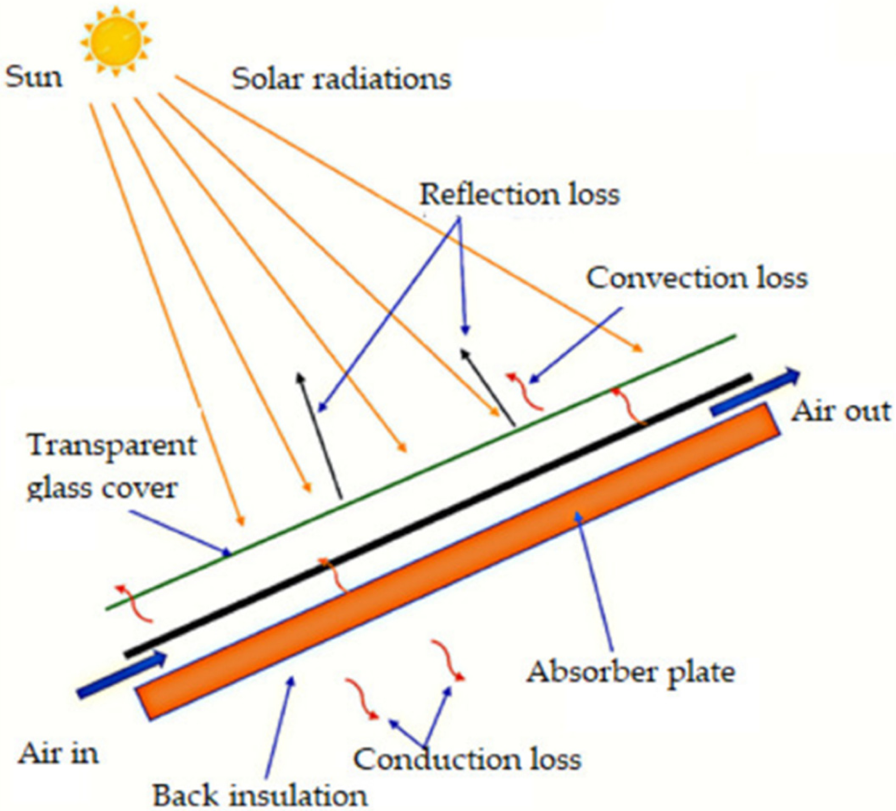
Schematic diagram of the proposed collector.
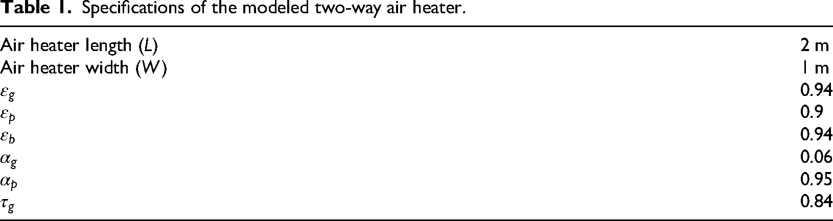
The air heater being studied is shown in Figures 2 and 3. This air heater is a two-way type, with dimensions of 2 m in length, 1 m in width, and 0.2 m in height. In this configuration, the air stream flows over the collector's upper surface, is redirected beneath the collector, and exits at the downstream end. The air heater has an absorber plate with V-shaped teeth, each tooth at a 60-degree angle. Initially, it is assumed that the gap between the absorber and the glass is 25 mm, and the height of the V-shaped teeth is 50 mm. The absorber plate is made of a steel-aluminum alloy covered in black paint, while the walls of the air heater are made of steel. These assumptions about the initial dimensions and materials used are made for comparison and validation purposes, following a study by Karim et al. (2014). After validation, these parameters are adjusted to investigate the effects of changing the gap between the glass and the absorber, as well as the height of the absorber teeth. The range of changes in the Reynolds number for the two air channels in this study, is calculated to be between 550 and 7600, as per equation (9).
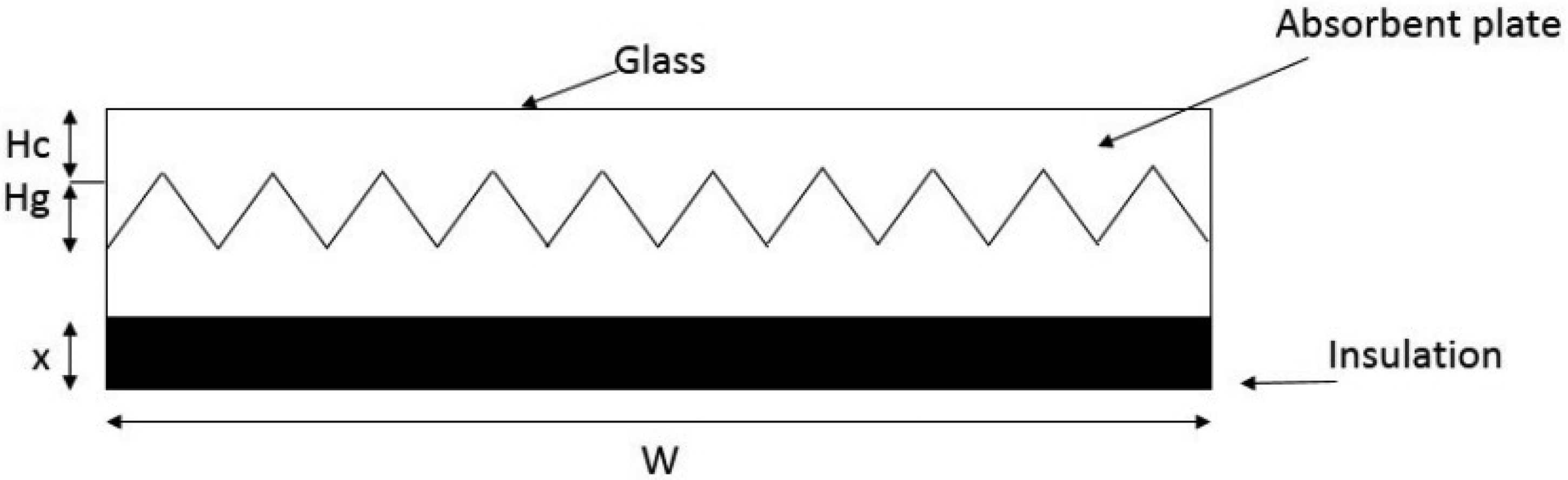
Schematic of the absorber plate with V-shaped teeth.
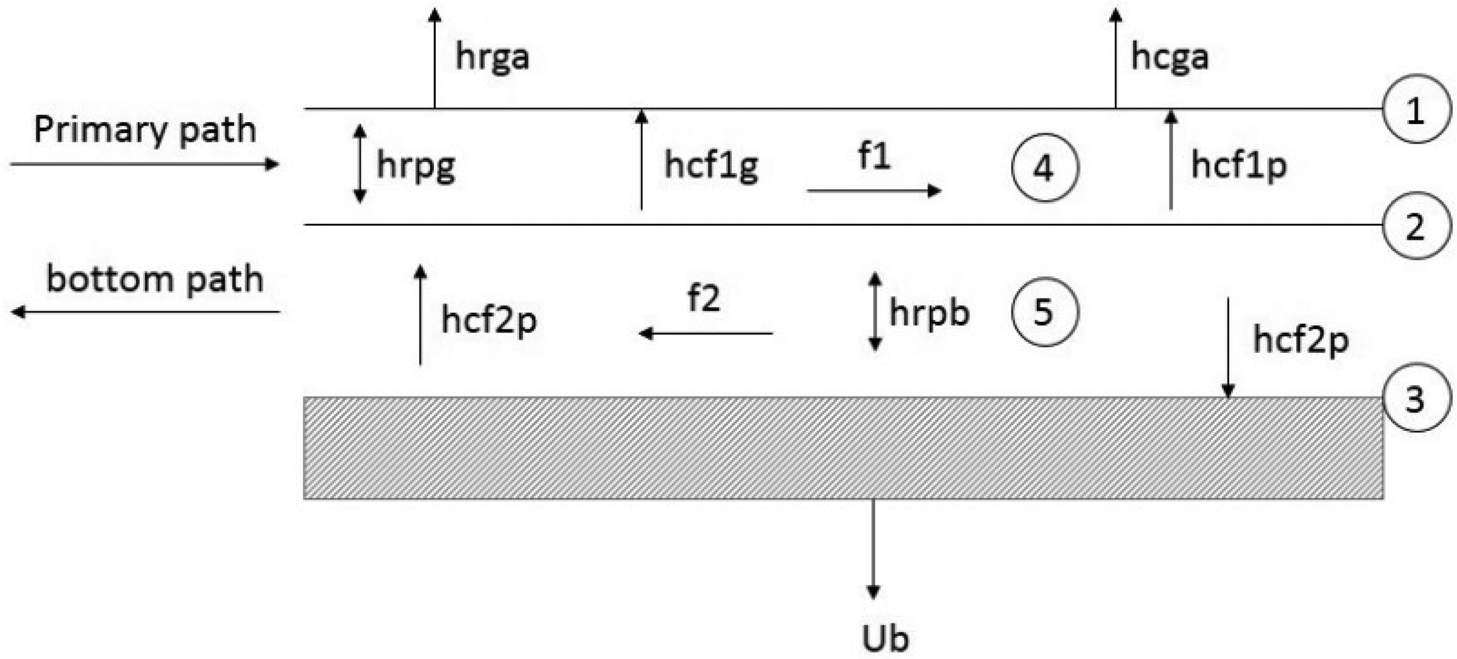
Schematic of a two-way solar air heater.
Figure 3 shows a diagram of a two-way air heater system. The components in the system include the glass cover (1), the absorber plate (2), the bottom plate (3), the air channel between the glass and the absorber (4), and the air channel between the absorber and the bottom plate (5). The heat transfer coefficients for radiation between the glass and the air, the absorber and the glass, and the absorber and the bottom plate are denoted as hrga, hrpg, and hrpb.
Additionally, the convection heat transfer coefficients between the glass and the air, the upper channel air and the glass, the upper channel air and the absorber, the lower channel air and the absorber, and the lower channel air and the bottom plate are represented as hcga, hcf1g, hcf1p, hcf2p, and hcf2b. Table 1 provides the specifications of the two-way air heater model, including the emission (εg, εp), absorption (αg, αp), and transmission (τg) coefficients for the glass and the absorber plate.
Specifications of the modeled two-way air heater.
Governing equations
The equations that control the components of the two-way air heater in relation to energy balance and exergy are as follows.
Energy balance equations
The total energy absorbed by the glass cover, including solar radiation and heat transfer between the air in the upper channel and the glass, as well as radiant heat transfer between the glass and the absorber, is equal to the energy dissipated through radiation and heat transfer between the glass and the surrounding air. This energy balance in the glass cover can be expressed as follows (Alayi et al., 2021, 2022):
In the equation above, S represents the intensity of solar radiation and is determined using equation (2) (Karim et al., 2014):
The coefficient of heat transfer for the glass in contact with the surrounding air is determined by utilizing the equation provided below (Karim et al., 2014):
The determination of the radiation heat transfer coefficient between the two plates is performed using the subsequent equation (Karim et al., 2014):
In order to find the convection heat transfer coefficient between the glass cover and the air inside the channel, the Nusselt number definition was used.
Taking into account the teeth of the absorber plate, the corresponding relationship is adjusted as indicated below:

In the equation mentioned earlier, Hc represents the distance from the absorber to the glass cover, while Hg indicates the height of the absorber plates. The energy absorbed by the air in the upper section of the air heater through heat transfer from the absorber to the air is equal to the heat transferred from the air to the glass. The energy balance in the air channel between the glass cover and the absorber plate is shown as follows:
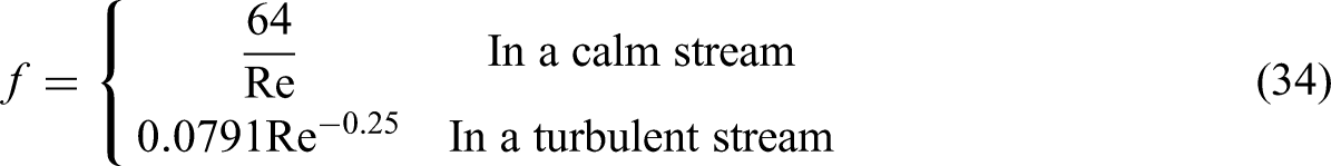
The Reynolds number is calculated using equation (9) (Karim et al., 2014):
The Nusselt number is determined based on the range of the Reynolds number. If Re < 2800, 2800 < Re < 104, or 104 < Re < 105, the Nusselt number is calculated using equations (10) to (12), respectively (Karim et al., 2014):


The energy conveyed to the absorber (through convection heat transfer from the air in the lower channel and radiation from the lower plate) is equivalent to the heat conveyed from the absorber to the air in the upper channel through convection and radiation from the glass. The energy balance in the absorber plate is determined using equation (13).
The energy imparted to the air in channel 2 via displacement with the bottom plate is equivalent to the energy communicated from the air to the absorber. The energy equilibrium in the air channel situated between the absorber plate and the bottom plate is determined using equation (14).
The energy gained by the bottom plate is equivalent to the total of the energy moved through convection from the air in channel 2, radiation from the absorber plate, and energy interchange with the surrounding air. The energy equilibrium in the bottom plate is determined using equation (15).
The coefficient of heat transfer in the lower plate is determined by utilizing equation (16):
Also, the efficiency of a two-way air heater with a V-shaped toothed absorber is calculated using equation (17) (Karim et al., 2014):
While energy analysis quantifies the useful thermal output of the collector, it does not account for the quality of that energy or the real potential for performing work. To address these limitations, the present study proceeds with an exergy analysis; which evaluates both the magnitude and quality of the thermal energy relative to the ambient environment. The modeling framework is developed under steady-state conditions, with constant inlet temperature, solar radiation intensity, and mass flow rate during each simulated case. Transient phenomena, such as thermal inertia of materials and diurnal solar variations, are neglected to allow a direct comparison of design configurations based solely on their steady-operating characteristics. This steady-state approach is widely adopted in solar air heater performance analysis and is suitable for optimization studies, where the goal is to identify parameter combinations that maximize thermal and exergy efficiencies without the confounding influence of time-dependent fluctuations.
Exergy balance equations
Exergy is the best possible work that can be done when a process happens without any energy loss. Energy analysis is based on the first law of thermodynamics, while exergy analysis comes from the second law of thermodynamics. In the study of thermal systems, the idea of exergy destruction or irreversibility was used to understand how energy is wasted or cannot be completely used. The useful energy from sunlight is calculated using the Petela equation (Alim et al., 2013; Dehghan et al., 2015).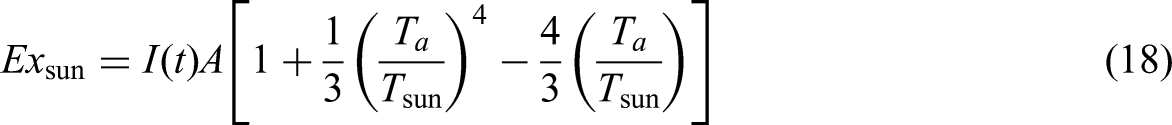
In equation (18), Ta represents the ambient air temperature while Tsun denotes the solar surface temperature, which is assumed to be 6000 degrees Kelvin. Additionally, I(t) and A refer to the solar radiation intensity and the surface area of the system that is in contact with the sun, respectively.
In the Petela formulation, the incident solar radiation is modeled as blackbody emission at an effective solar temperature of Ts = 6000 K. This simplification is valid because: (i) the angular diameter of the sun is extremely small, allowing radiation to be treated as collimated, (ii) the effective temperature of 6000 K has been experimentally determined from the solar spectrum at the top of the atmosphere, and (iii) the purpose of the exergy model is to compare configurations under identical irradiance conditions, making relative performance metrics insensitive to minor non-blackbody effects. All simulations are conducted under standard AM1.5 global solar spectrum assumptions, with attenuation modeled in optical efficiency terms rather than in the Petela radiation exergy term itself. This approach is consistent with previous solar air heater modeling studies (Karim et al., 2014; Kumar and Layek, 2022).
Furthermore, the exergy transfer from a system at temperature T to the environment at temperature Ta is determined using equation (19).
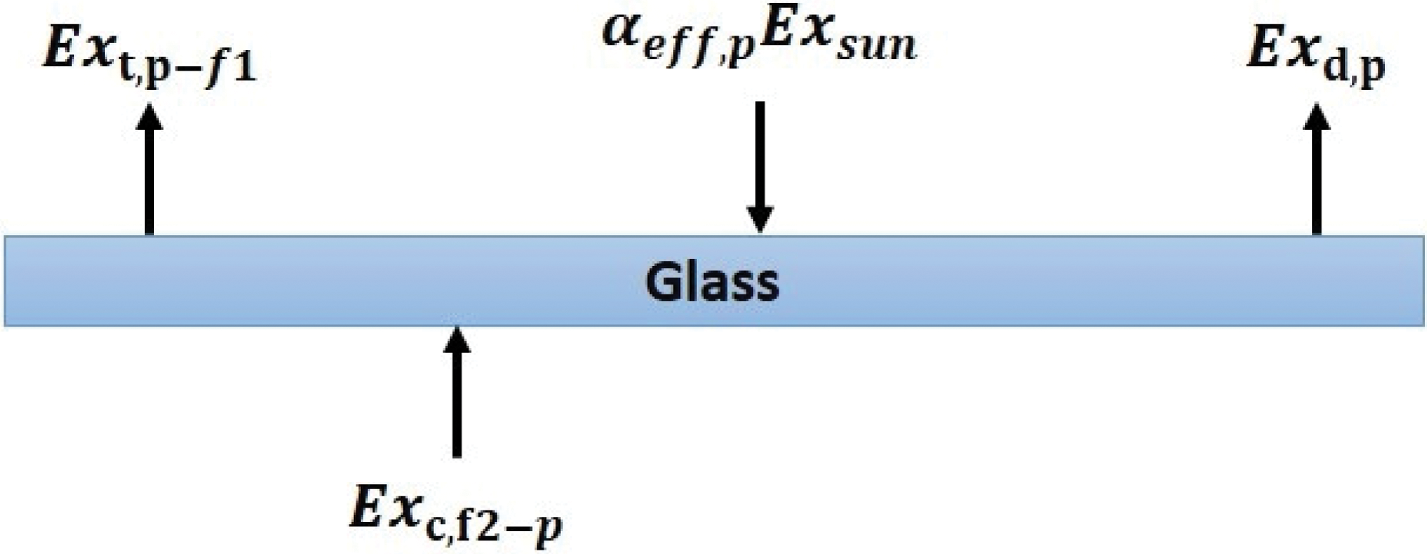
In the above equation, Q represents the heat transfer resulting from conduction, convection, and evaporation. Figures 4 to 6 shows exergy balance in glass coating, absorber plate bottom plate. The exergy depletion in glass is derived from the equation below.

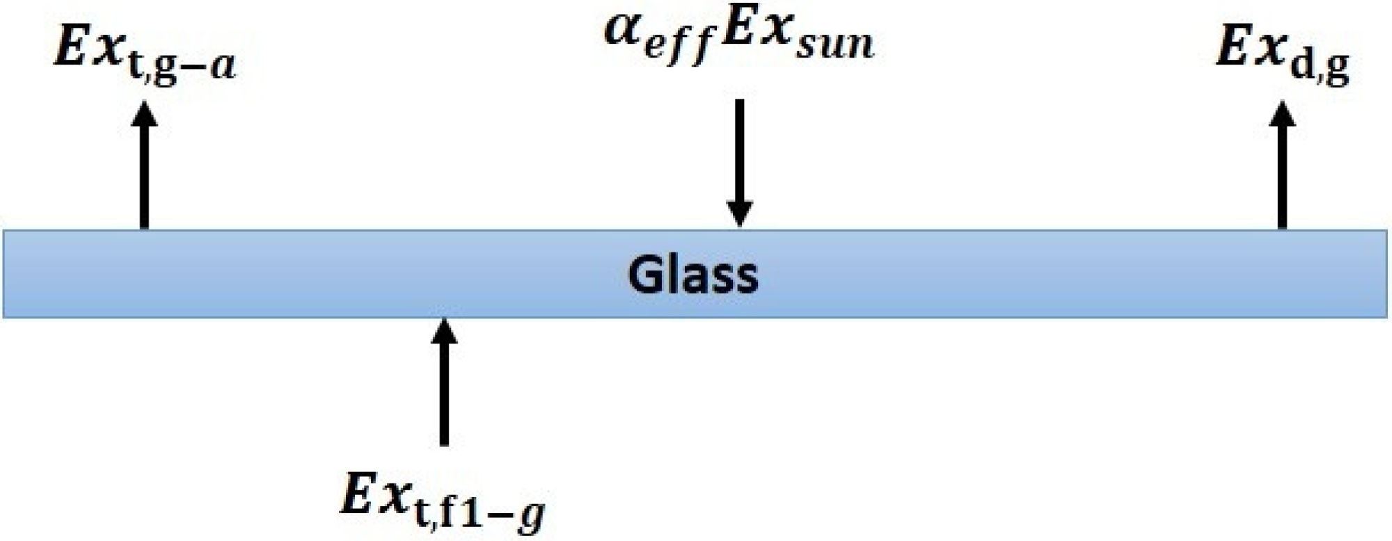
Exergy balance diagram in glass coating.
Exergy balance diagram on the absorber plate.
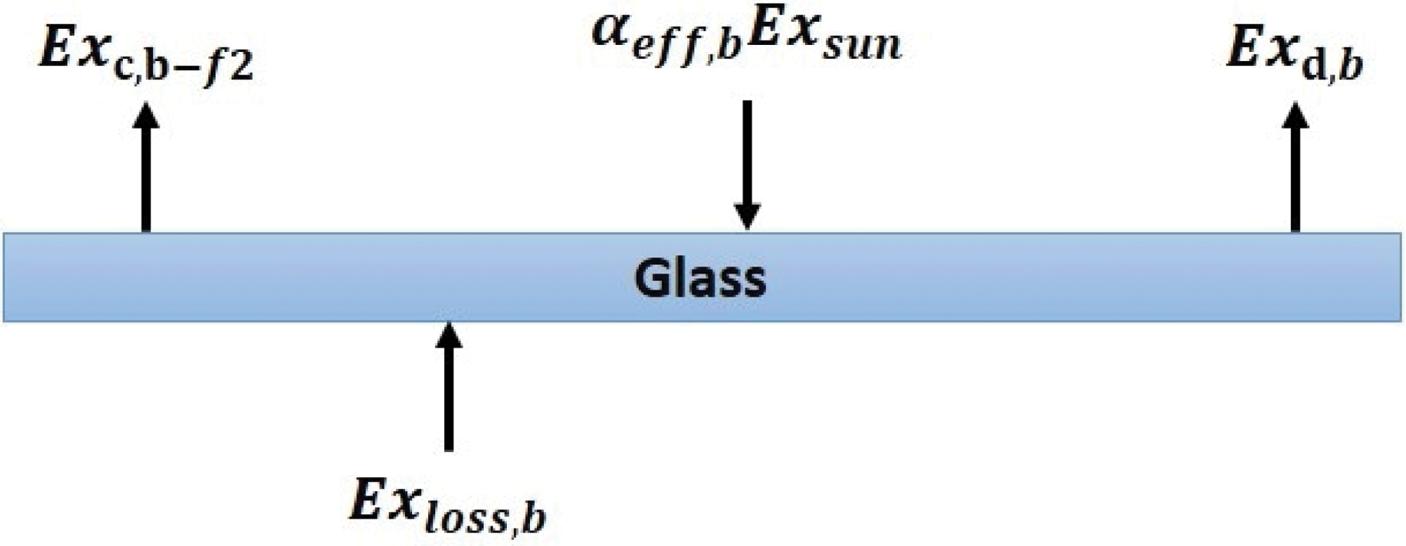
Exergy balance diagram on the bottom plate.
The exergy destruction in the lower plane is according to equation (22).


The exergy obtained from the sun by the air in channel 1 is represented by αeff−f1Exsun. Exc−p−f1 denotes the exergy transferred from the absorber to the air in channel 1 (Figure 7), and Ext−f1−g indicates the total exergy related to the heat transfer between the glass and the air in the upper channel. Additionally, ΔExf1 represents the exergy accumulated in the air in channel 1. The exergy loss in the air channel between the absorber and the bottom plate is determined using equation (25) (Dehghan et al., 2015).

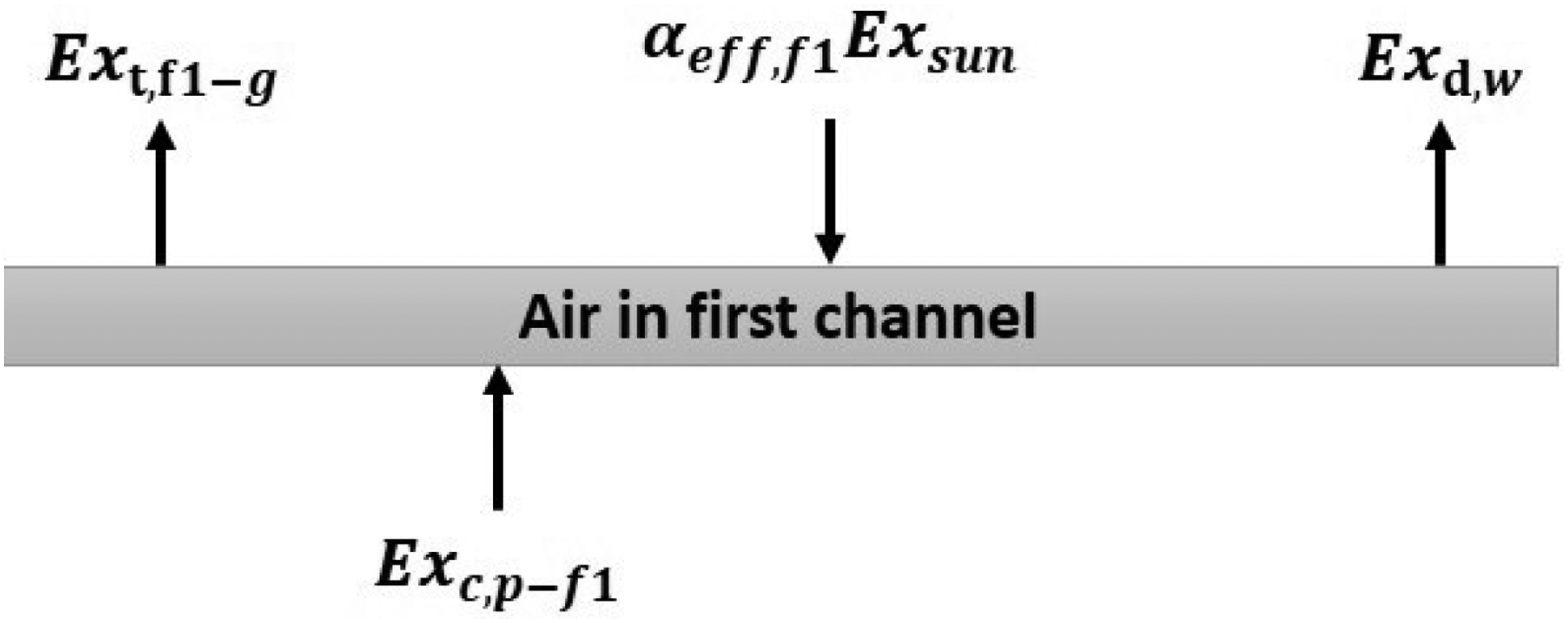
Exergy balance diagram in the air channel between the glass and the absorber.
In the equations above, αeff−f2Exsun represents the exergy absorbed from the sun by the air in channel 2. Exc−p−f2 represents the exergy transferred from the absorber to the air in channel 2. Ext−f2−p indicates the total exergy associated with the heat transfer between the absorber and the air in channel 2. ΔExf2 is the exergy stored in the air in channel 2 (Figure 8). Equation (27) characterizes the exergy efficiency in terms of the rate of exergy lost and exergy input to the system.

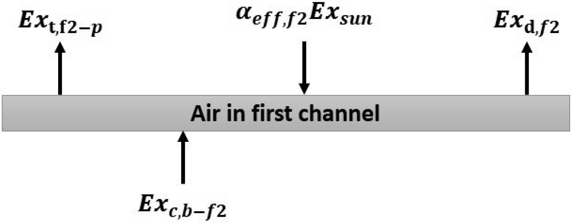
Exergy balance diagram in the air channel between the absorber and the bottom plate.
The exergy input to the air heater is defined as follows.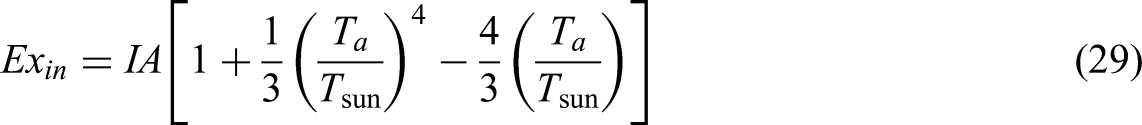
The output exergy without pressure drop is defined in equation (30) (Bahrehmand et al., 2015).
The exergy derived from the work of the fan is expressed by the subsequent equation, in which Ta represents the ambient air temperature and Ti the inlet air temperature:
The fan work is obtained from the equation (32) (Bahrehmand et al., 2015).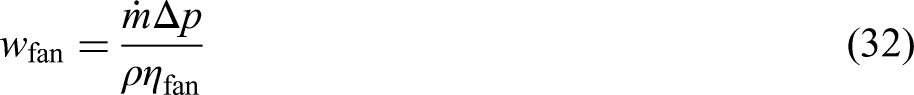
The pressure difference resulting from the fan is also defined as follows.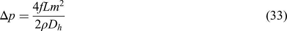
The novelty of the present modeling framework lies in its joint optimization of serrated absorber plate geometric parameters—specifically, the tooth height and intertooth gap—together with operational mass flow rate. Unlike conventional solar air heater studies that treat thermal and hydraulic analyses separately, the present model couples both in a unified energy–exergy structure. Net exergy efficiency calculations account for the work required to overcome pressure drop, thereby explicitly incorporating fan power into the optimization process. This allows for a rigorous evaluation of geometry–flow interactions and their practical operational tradeoffs.
Conventional flat-plate solar air heaters typically rely on smooth absorber surfaces, which offer low pressure drop but limited heat-transfer enhancement due to stable boundary-layer development. In contrast, serrated absorber surfaces—characterized by repeated tooth-and-gap profiles—promote periodic boundary-layer disruption and turbulence generation along the flow path. This leads to more uniform temperature distribution, greater absorber-air contact effectiveness, and improved energy quality. Published works on finned and serrated geometries report substantial rises in thermal performance (often exceeding 10% in steady operation) and notable exergy improvements compared to smooth plates, while fabrication remains feasible with established metal-forming processes. The tradeoff is a modest increase in pressure drop, generally considered acceptable in systems where forced convection is already present. Thus, from a practical design standpoint, toothed absorbers offer a superior performance-versus-loss balance in applications where higher efficiency and reduced irreversibility are priorities.
Numerical solution
The energy balance equations for the two-way air heater were solved using MATLAB software. Initially, it was assumed that the temperature of the system components matched the ambient air temperature. The governing equations of the system were then solved simultaneously using the fourth-order Runge-Kutta method to determine temperatures in different components of the air heater, including the outlet air temperature. Energy efficiency and exergy of the system were determined by using relevant relations. A flowchart illustrating the equation-solving process can be found in Figure 9.
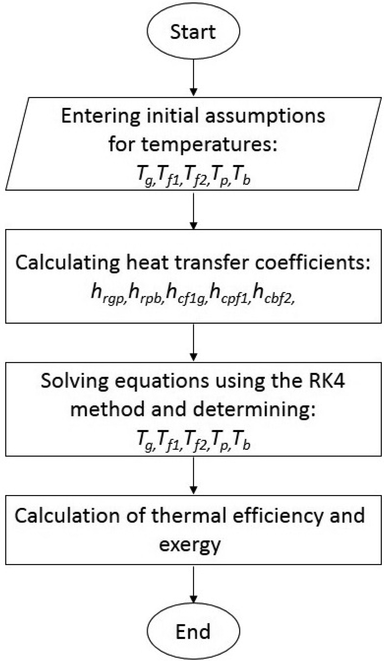
Flowchart of how to solve the problem.
The numerical solution begins with defining the initial thermal state of all collector components based on assumed starting conditions. With these baseline values in place, the program determines the heat-transfer characteristics for every relevant surface and air passage, capturing both radiative and convective interactions. It then proceeds to solve the complete set of governing energy equations using a stable iterative method that updates temperatures until all parts of the system reach a consistent thermal balance. Once this steady state is achieved, the overall thermal and exergy performance of the solar air heater is evaluated from the final temperature field. In cases where a parametric study is conducted, the chosen operating or design parameter is modified and the entire calculation sequence is repeated. The flowchart depicts this closed-loop process, showing how definitions, calculations, and evaluations are interconnected to produce the performance outcomes discussed in subsequent sections.
Validation of mathematical modeling results
In order to confirm the accuracy of the mathematical modeling process and the results obtained from the code created with MATLAB software, the findings was compared with the research conducted by Karim et al. (2014). Figures 10 and 11 show the graphs illustrating the changes in solar radiation intensity and ambient air temperature used in this study.
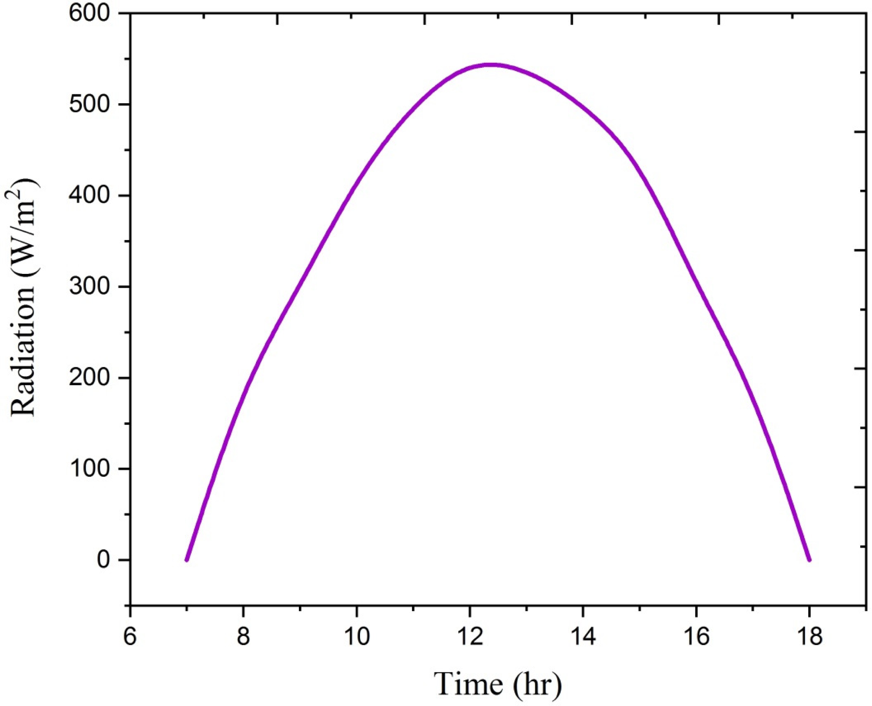
Changes in solar radiation intensity over time in the work of Karim et al. (2014) and the present work.
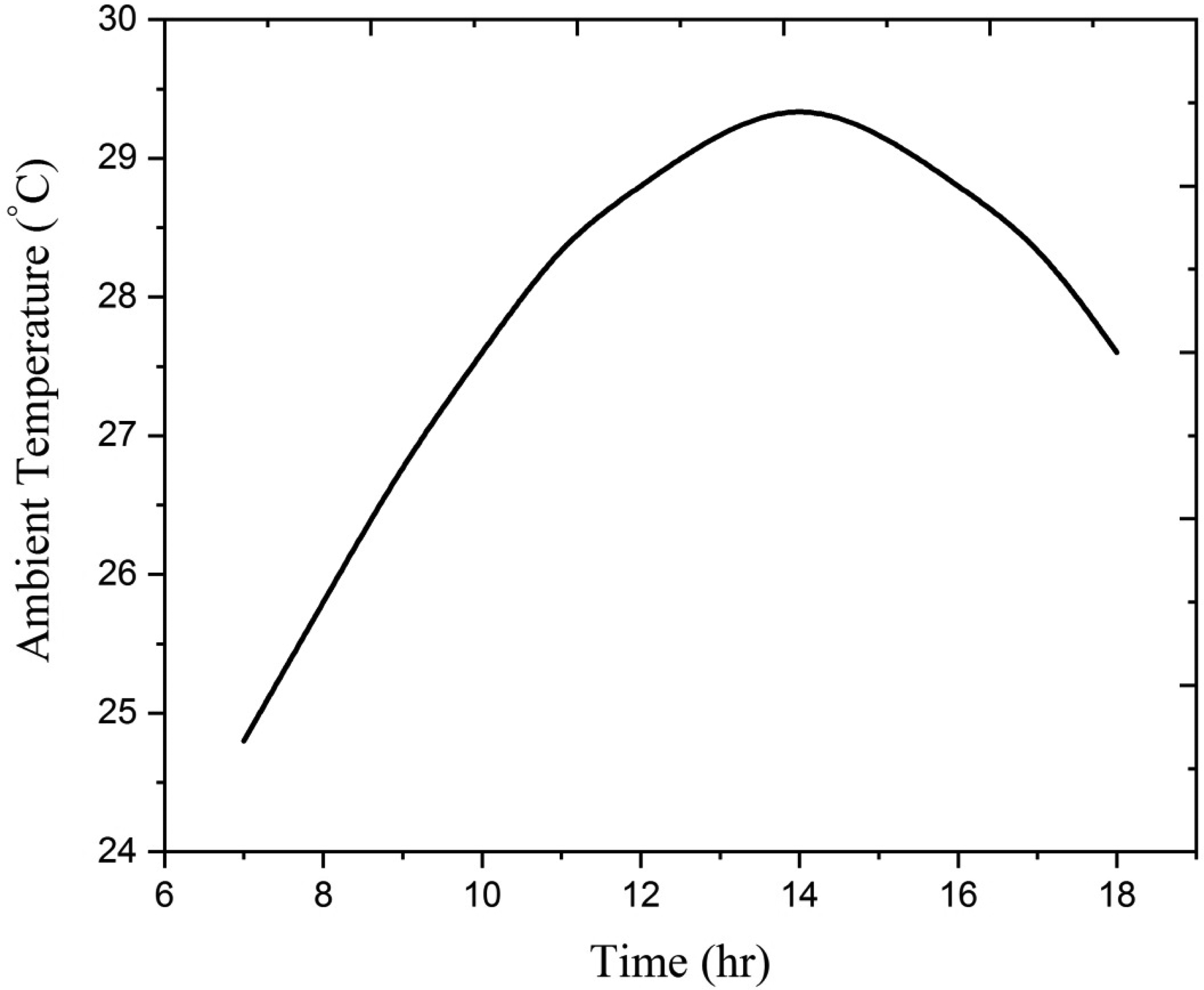
Changes in ambient air temperature over time in the work of Karim et al. (2014) and the present work.
In Figure 12, the temperature variations of an air-heated glass coating over time were compared between Karim et al. (2014) and the current research, using an air mass flow rate of 0.035 kg/m2s. The discrepancy between the experimental and modeling results is around 4%. Figures 13 and 14 show the temperature variations of the air in the channel between the glass and the absorber, and the channel between the absorber and the bottom plate, with a mass flow rate of 0.035 kg/m2s. The largest difference between the experimental and modeling results in this study is approximately 9%.
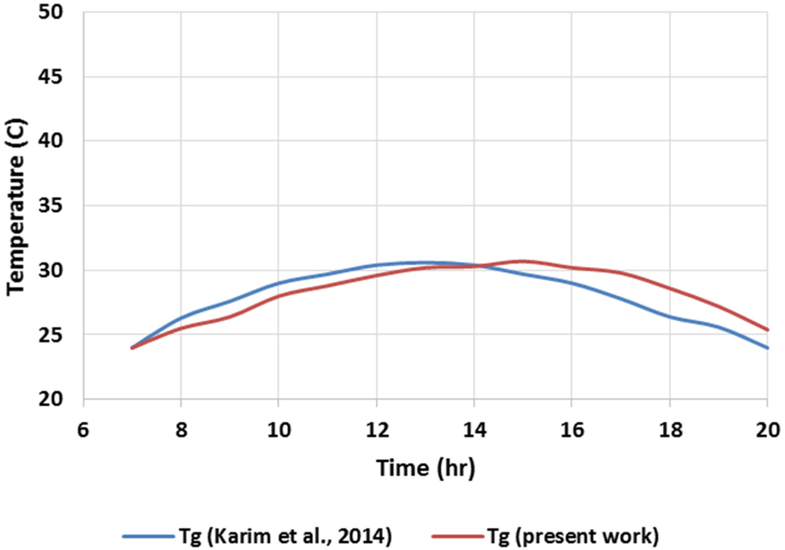
Comparison of changes in glass coating temperature over time in the work of Karim et al. (2014) and the present work.
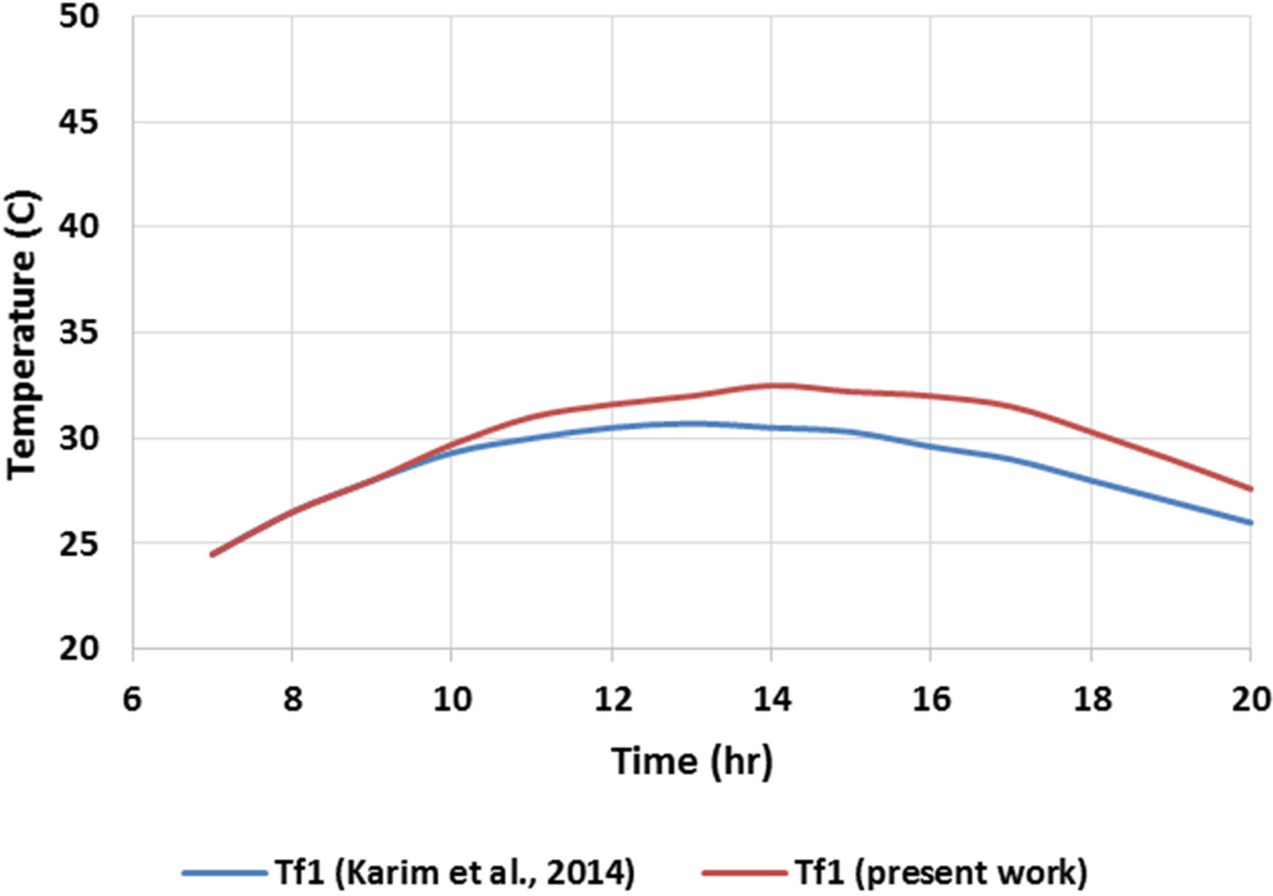
Comparison of air temperature changes between the glass cover and the absorber plate over time in the work of Karim et al. (2014) and the present work.
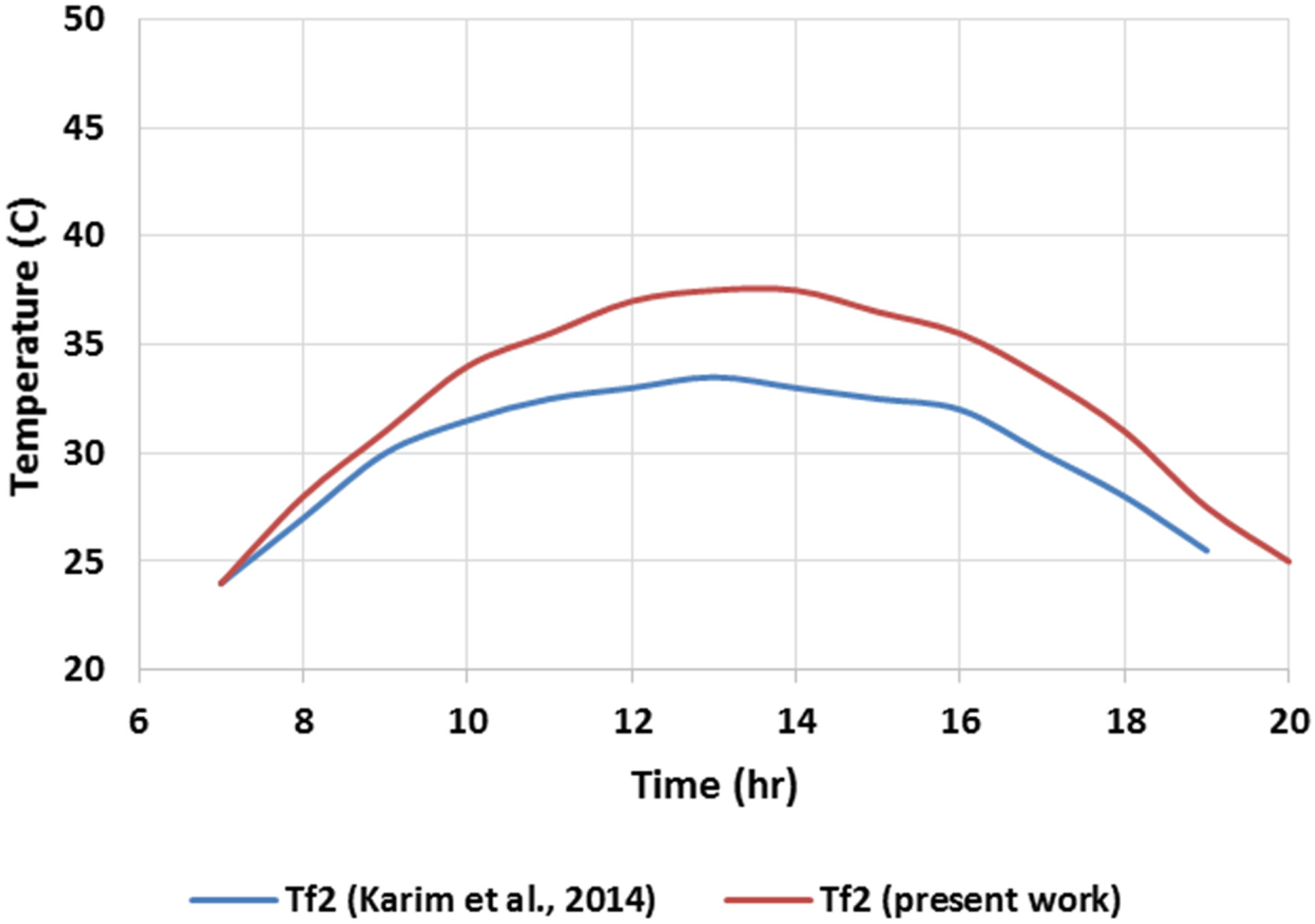
Comparison of air temperature changes between the absorber plate and the bottom plate over time in the work of Karim et al. (2014) and the present work.
The graphs in Figures 15 and 16 show how the temperatures of the absorber plate and bottom plate change over time. The biggest difference between the results from Karim et al. (2014) and the results from this research is 10%.
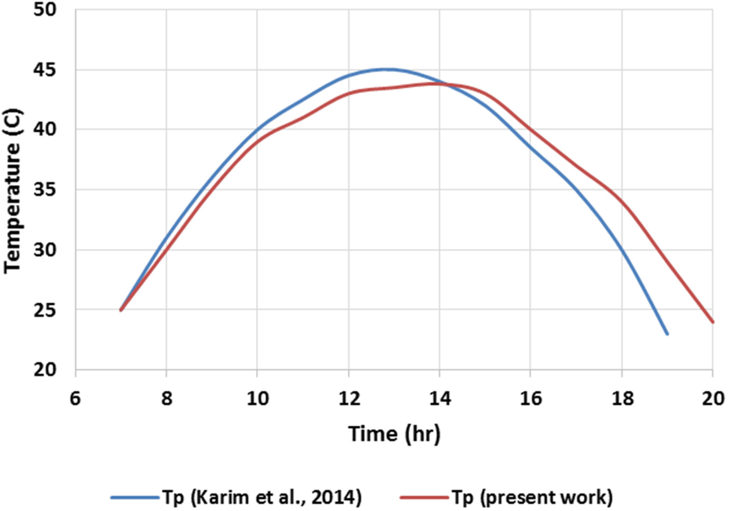
Comparison of the changes in the temperature of the absorber plate with respect to time in the work of Karim et al. (2014) and the present work.
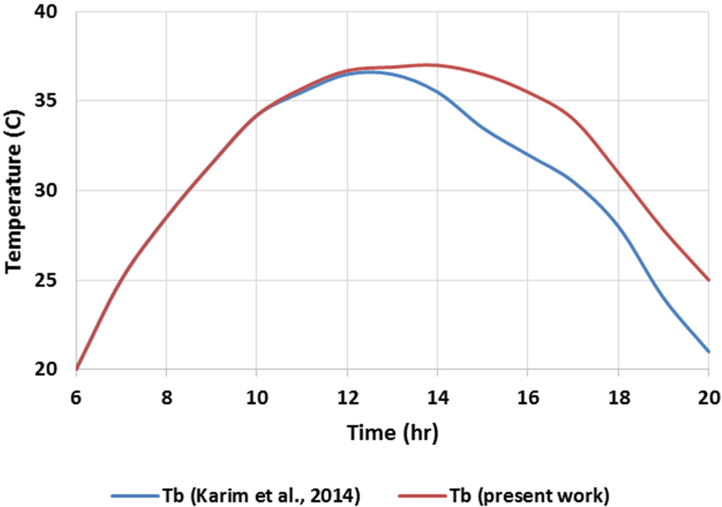
Comparison of the changes in the temperature of the bottom plate with respect to time in the work of Karim et al. (2014) and the present work.
The numerical predictions for Nusselt number (Nu) and friction factor (f) obtained from the present serrated absorber plate model were first benchmarked against the computational results of Karim et al. (2014) for similar flow and thermal boundary conditions, showing excellent agreement (mean deviation in Nu < 3.2%, f < 4.1%). While this ensured numerical consistency, it further addressed the reviewer's point regarding experimental validation by comparing the results with published laboratory measurements for geometrically related turbulence-promoting absorbers in solar air heaters. Specifically, it extracted experimental datasets from Sinsang et al. (2024) who investigated V-pattern ribs with semicircular perforations; and Kumar and Layek (2022) who tested twisted staggered V-shaped ribs using liquid crystal thermography.
Although the rib configurations in these works differ from the serrated geometry, all three designs operate under a similar mechanism of boundary-layer disruption and secondary-flow generation. The experimental ranges of Re, Nu, f, and thermal performance factor (TPF) provide a credible empirical context for the predictions. Table 2 contrasts the model outputs at representative Reynolds numbers with the benchmark experimental trends. The comparison shows good qualitative agreement in the direction and relative magnitude of performance changes—Nu enhancement within the 6% to 43% range and TPF maxima between 2.4 and 2.7—matching reported experimental envelopes. The differences in absolute values, where present, are attributed to geometric disparities, channel aspect ratio, and roughness pitch/height ratios. This hybrid validation approach—combining numerical–numerical benchmarking with experimental trend assessment—reinforces the robustness of the proposed modeling framework.
Comparison of present model results with experimental literature data for turbulence-promoting absorber geometries in solar air heaters.
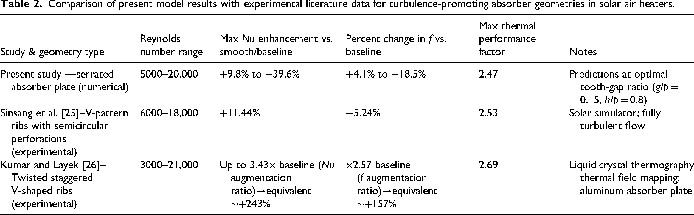
The present validation relies partly on experimental data from geometries with comparable turbulence-enhancement mechanisms but different physical dimensions and rib shapes. While this strengthens the credibility of predicted trends, the absence of direct physical testing on the serrated plate design under identical conditions remains a limitation. This will be addressed in future work by designing and fabricating a prototype for controlled testing in a closed-loop solar air heater facility.
Results and discussion
Table 3 summarizes the exergy destruction budget for the three primary components—glass cover, absorber plate, and bottom plate—under optimal tooth height, gap, and mass flow rate conditions. The absorber plate accounts for the highest proportion of exergy destruction due to its elevated surface temperature and direct exposure to the concentrated heat flux.
Exergy destruction breakdown under optimal conditions.
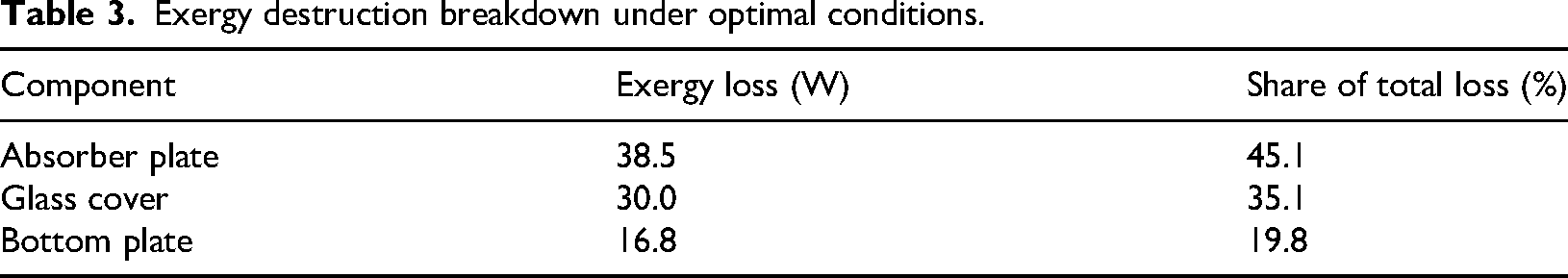
These results indicate that improving absorber plate thermal properties or introducing selective coatings could significantly reduce overall exergy destruction. The glass cover's notable share reflects radiative and convective heat losses to the environment, suggesting further optical design optimization. Losses through the bottom plate, though smaller, may still benefit from enhanced insulation strategies.
Figures 17 and 18 show how thermal efficiency and exergy efficiency change based on the distance between the glass and the absorber plate for different mass flow rates. As the distance between the glass and the absorber plate increases, thermal efficiency goes up by about 9% on average, and exergy efficiency increases by around 18%. This is because as the distance increases, the Reynolds number also increases, leading to a higher convection heat transfer coefficient. In one study, at a mass flow rate of 0.035 kg/m2s, the Reynolds number range goes from 2500 to 3800 when the distance between the glass and the absorber plate is increased from 1.25 to 10 cm. This causes the temperature difference between the fluid entering and exiting the air heater to increase, resulting in higher first-law and second-law efficiency. When the mass flow rate increases from 0.01750 to 0.035 kg/m2s and from 0.035 to 0.07 kg/m2s, thermal efficiency goes up by approximately 14% and 3%, respectively. Exergy efficiency, on the other hand, decreases by about 65% and 58%, respectively, as the mass flow rate increases. This decrease in exergy efficiency at higher mass flow rates is due to the increase in entropy production, leading to more irreversibility in the system and higher exergy destruction rate. Therefore, according to the second-law efficiency relation (equation (27)), exergy efficiency decreases.
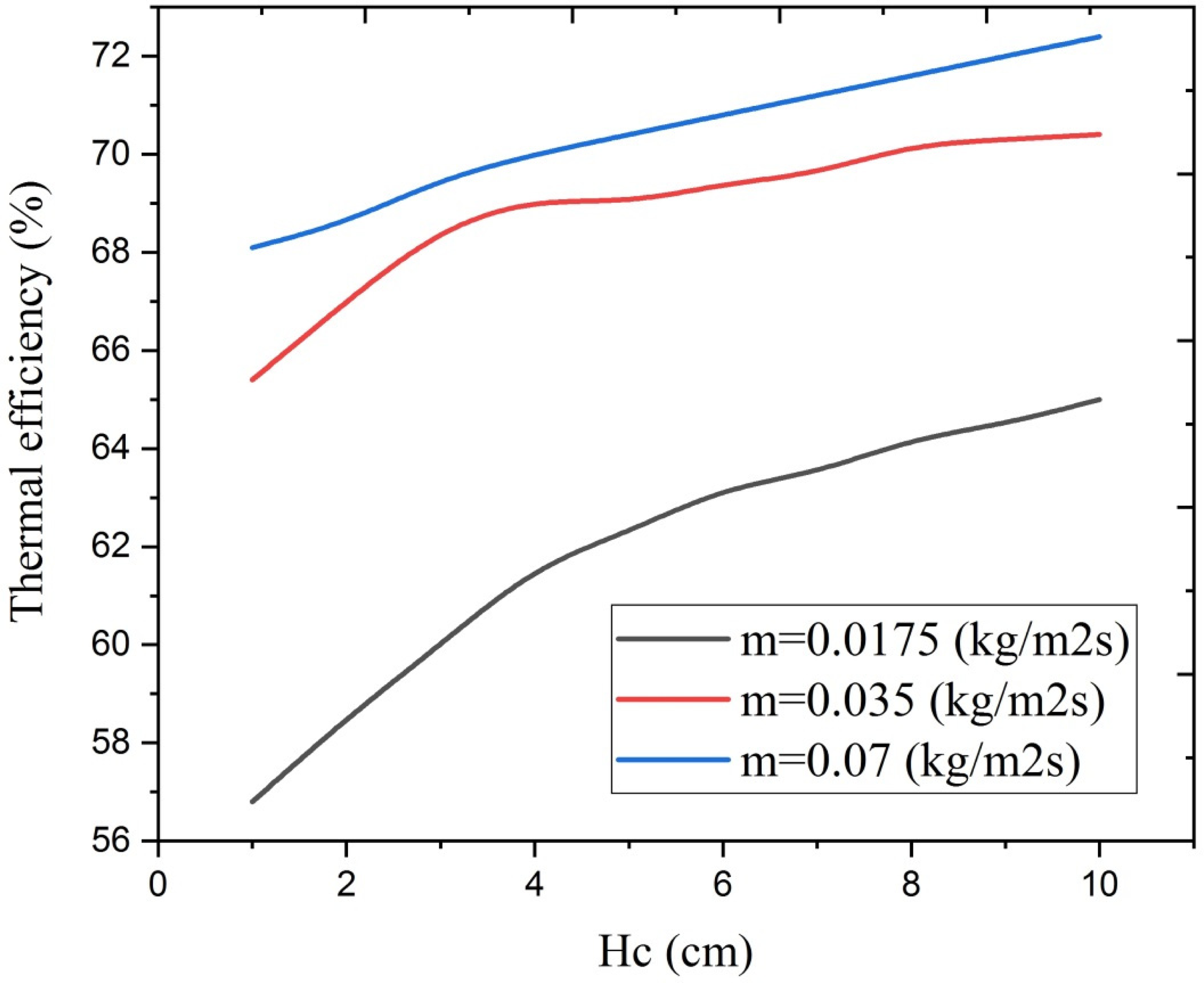
Changes in thermal efficiency depending on different distances between the glass and the absorber with changing mass flow rate.
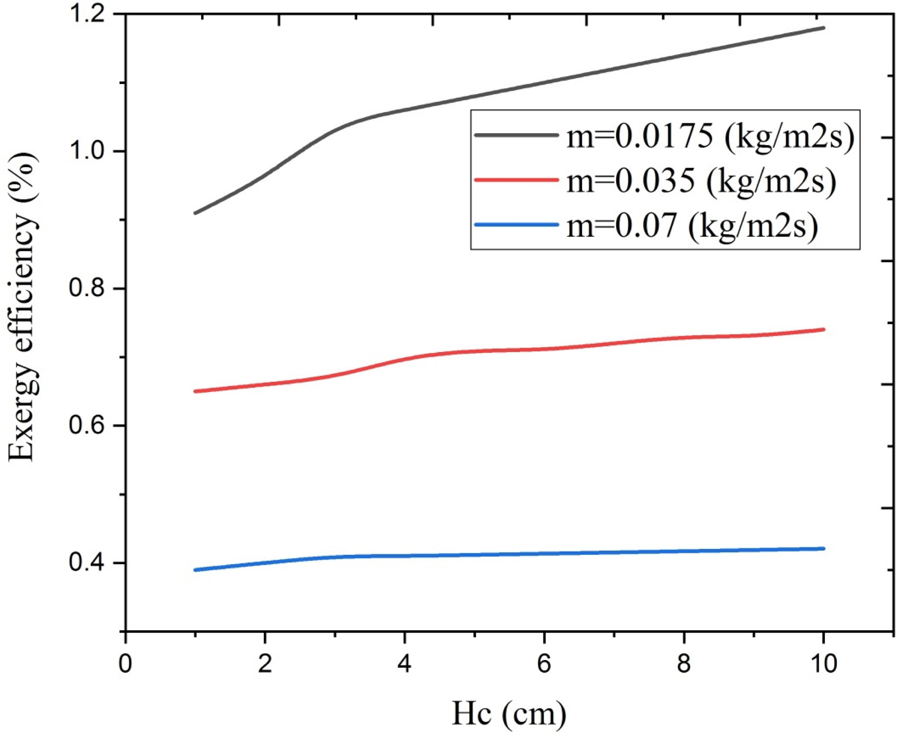
Variation of exergy efficiency with different distances between the glass cover and Hc at different mass flow rates.
The graph in Figure 19 shows how thermal efficiency changes over time at different distances (1.25, 2.5, 5, 7.5, and 10 cm) between the glass and the absorber plate. The thermal efficiency increases until noon when solar radiation is at its peak, then gradually decreases. Increasing the distance between the glass and the absorber plate to 10 cm improves thermal efficiency because it creates a larger temperature difference between the glass and the air flowing into the channel. When the distance between the glass and the absorber plate is expanded, the hydraulic diameter increases according to equation (7). This results in lower air velocity in the upper channel, allowing for better heat transfer. This leads to an overall improvement in system performance and efficiency. Figure 20 illustrates the changes in exergy efficiency over time at different distances between the glass and the absorber plate. Increasing the distance from 1.25 to 10 cm results in a 19% increase in exergy efficiency. The higher distance leads to a higher convection heat transfer coefficient, improving heat transfer. By reducing the rate of exergy destruction using the equations provided (equations (27)–(30)), exergy efficiency is enhanced.
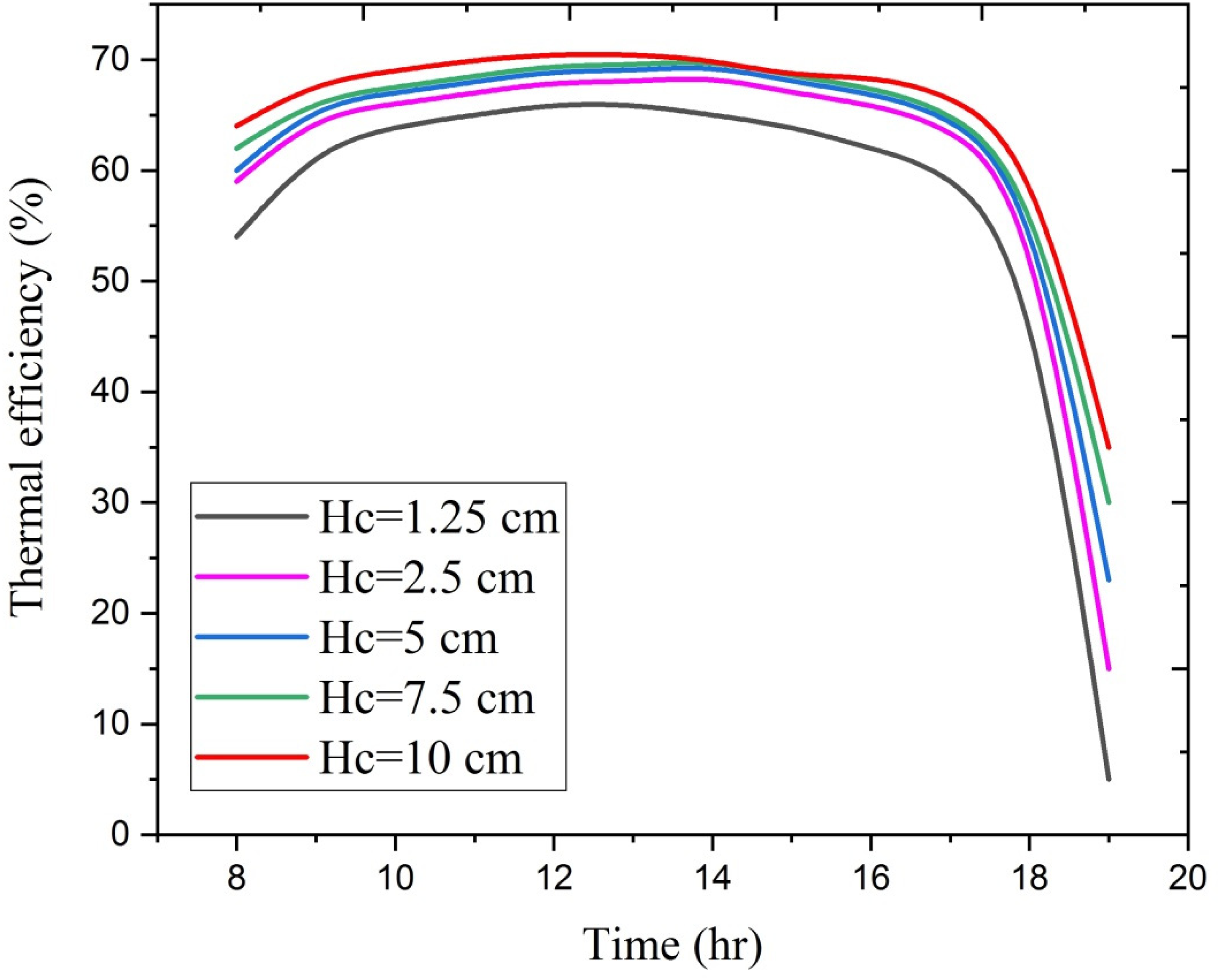
Changes in thermal efficiency over time for different distances between the glass and the absorber plate (Hc).
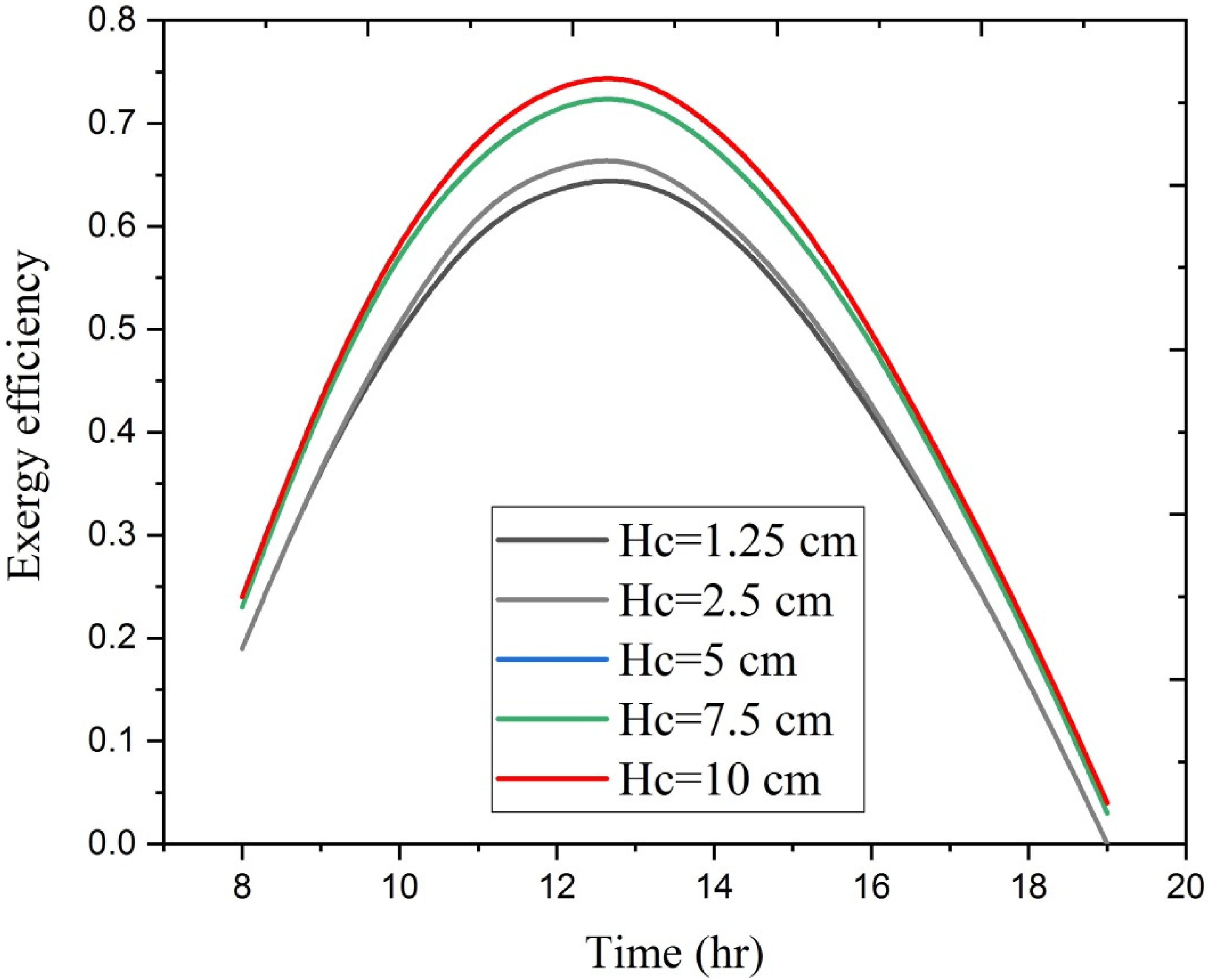
Changes in exergy efficiency over time with changing the distance between the glass and the absorber plate.
The graph in Figure 21 shows how exergy efficiency changes over time at mass flow rates of 0.017, 0.035, and 0.07 kg/m2s. It is clear that exergy efficiency decreases as the mass flow rate increases. This is because an increase in mass flow rate causes a change in entropy, leading to a decrease in exergy efficiency. This is because both entropy production and irreversibility of the system increase with a higher mass flow rate. Therefore, exergy efficiency decreases according to the established relationships. Additionally, the graph in Figure 21 demonstrates that exergy efficiency increases until noon at any specific mass flow rate due to the peak intensity of solar radiation during these hours, after which it starts to decline.
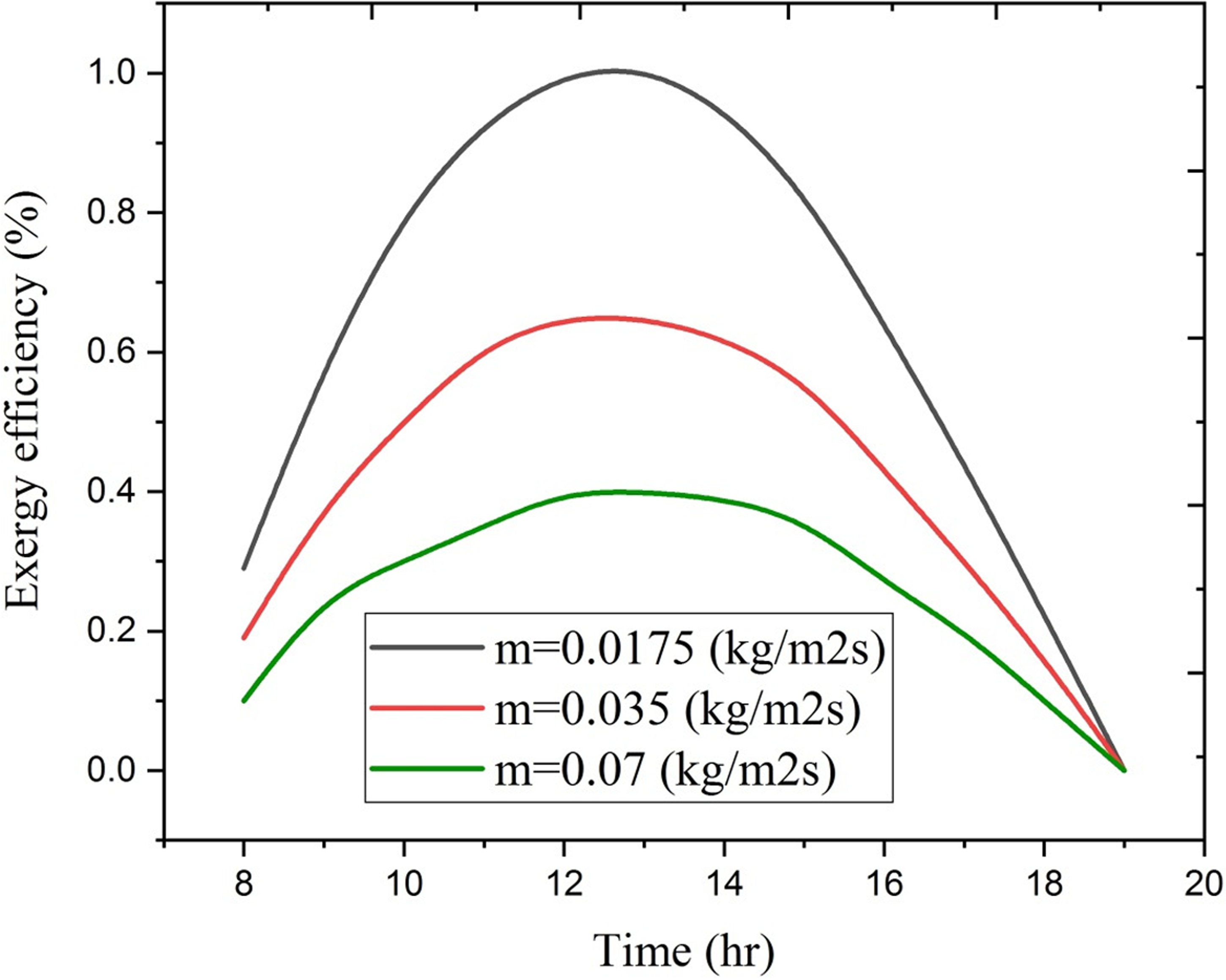
Changes in exergy efficiency over time for different mass flow rates.
Figure 22 shows how the air outlet temperature from the air heater changes over time at different mass flow rates. At 12 noon, when the temperature is at its highest, the air outlet temperature decreases by about 3% as the mass flow rate increases from 0.017 to 0.07 kg/m2s. This happens because the rates of radiant heat transfer and convection to the air in the duct decrease as the airflow inside it increases. Additionally, the air outlet temperature at each mass flow rate initially goes up and then goes down after the peak hours of solar radiation. This is because the solar radiation decreases, causing less energy to be absorbed by the airflow, which in turn lowers the air outlet temperature.
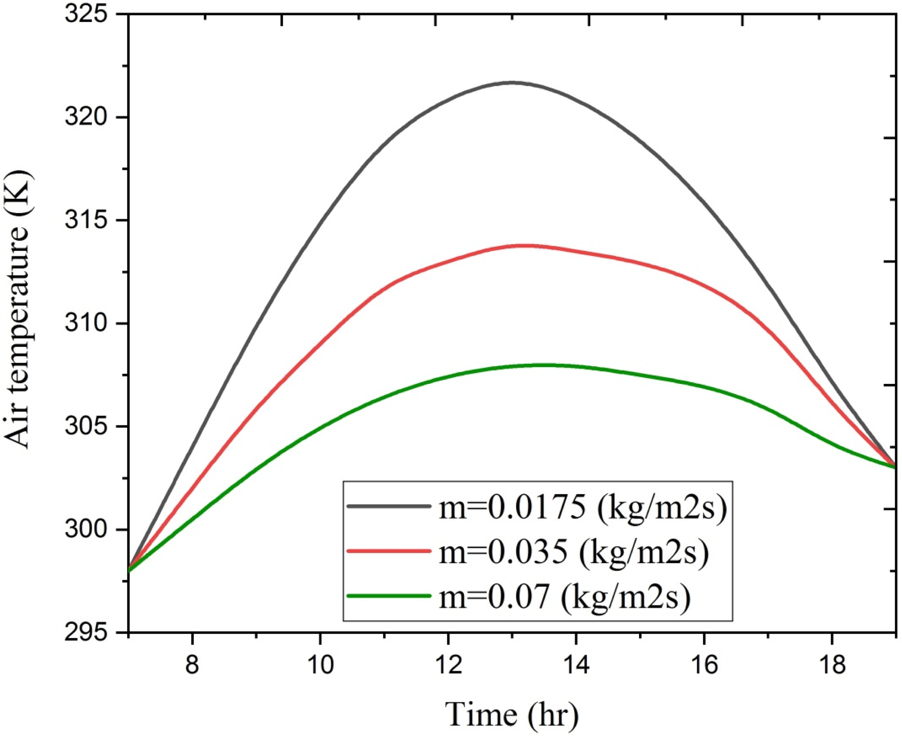
Variations of air temperature from the air heater with time for different mass flow rates (m).
Figures 23 and 24 illustrate the impact of tooth height and exergy absorber plate design on thermal efficiency and Hg efficiency for three different mass flow rates. When the height of the absorber plate teeth exceeds 10 cm, the energy and exergy efficiency of the air heater slightly decreases and then stabilizes. This is because as the V-shaped teeth of the absorber plate get taller, heat transfer to the air in the channel decreases due to increased pressure drop. This reduction in pressure results in less time for the fluid to exchange heat. Moreover, as the mass flow rate of air entering the air heater increases from 0.0175 to 0.07 kg/m2s, thermal efficiency goes up by 18% while exergy efficiency decreases by around 40%.
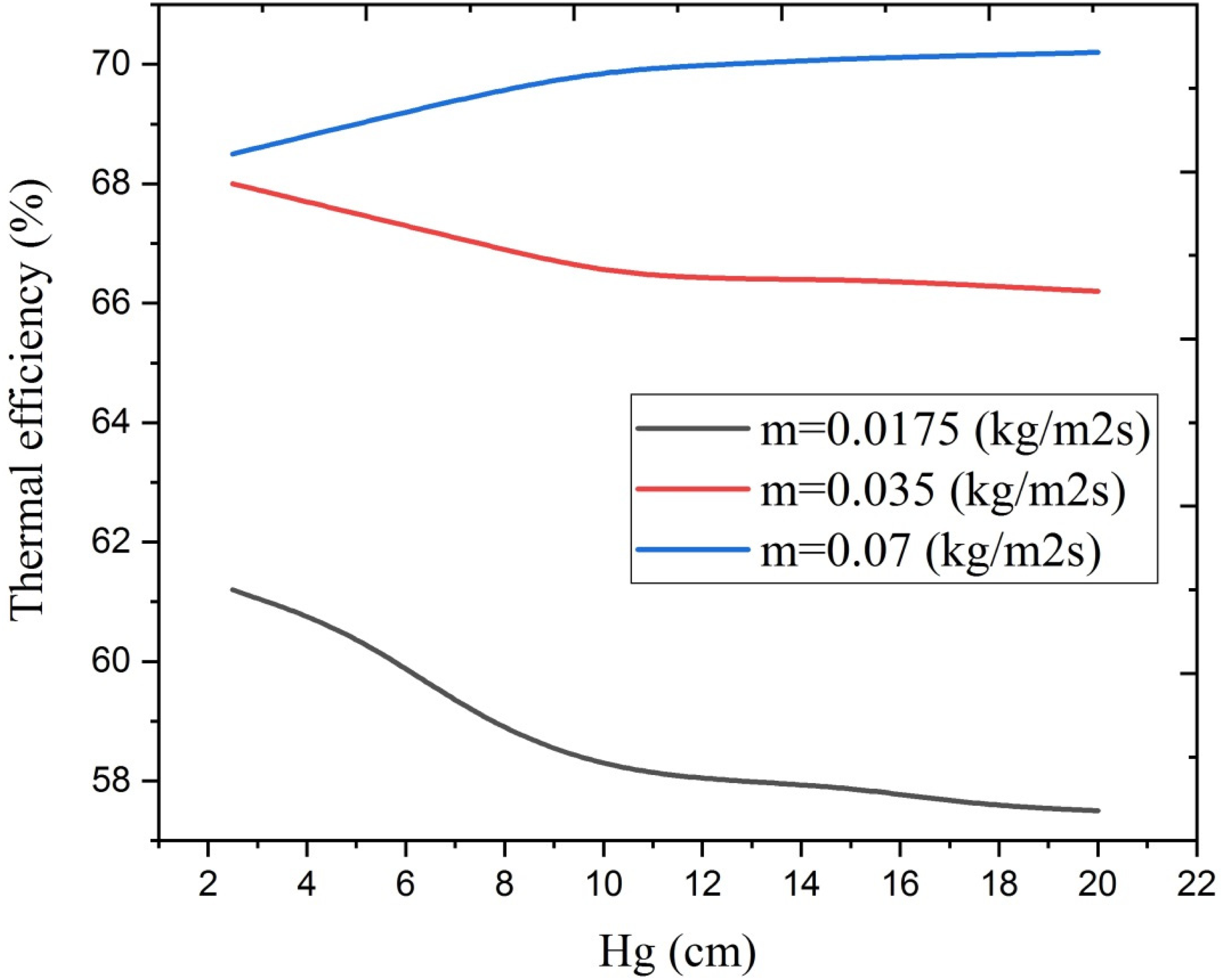
Changes in thermal efficiency depending on different heights of V-shaped teeth of the absorber plate (Hg).
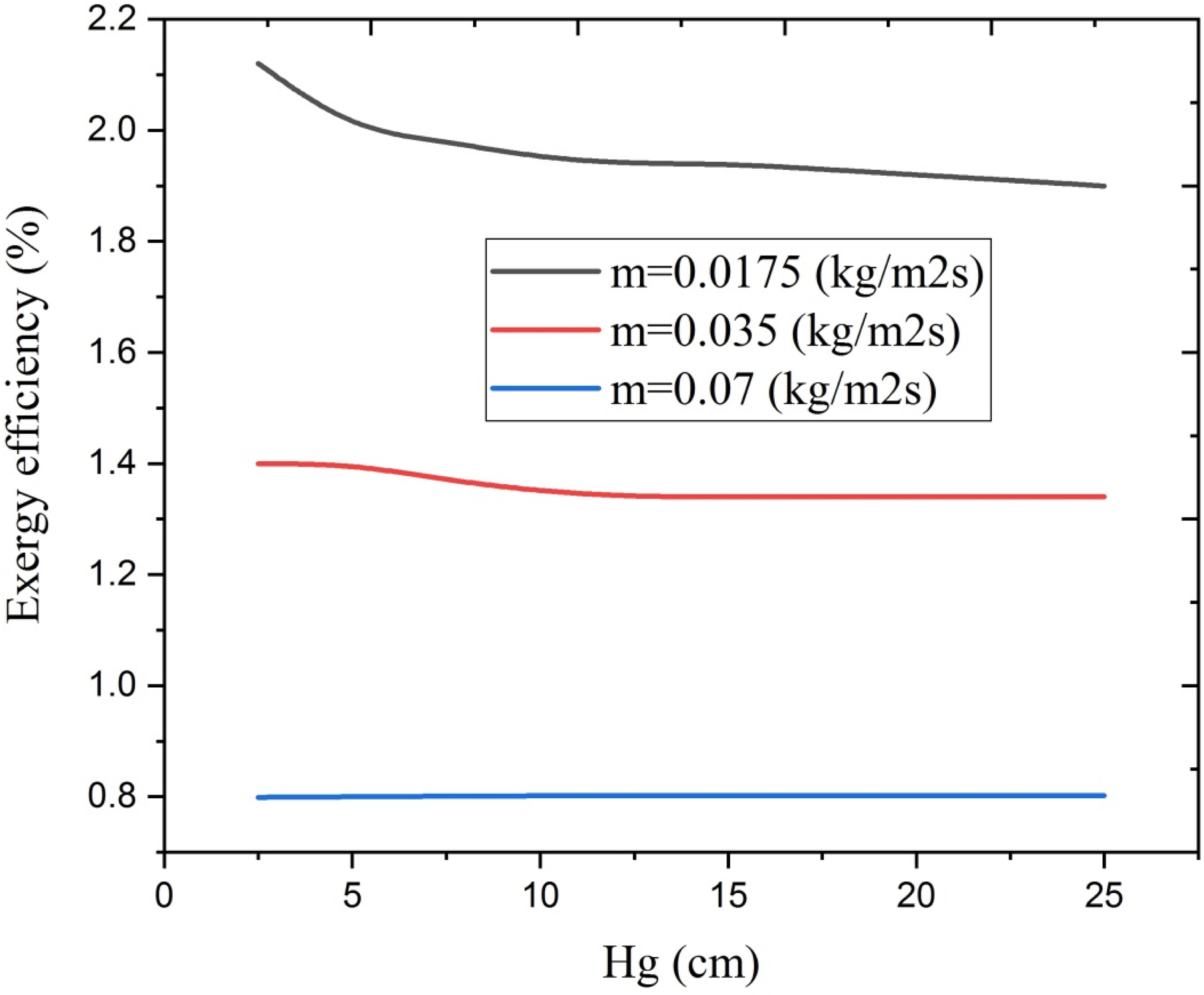
Changes in exergy efficiency according to different heights of the absorber teeth and plate shape (Hg).
The graph in Figure 25 shows how exergy efficiency changes with solar radiation intensity. It is clear that as the intensity of solar radiation increases, the exergy efficiency of the air heater being studied also increases by 61%, 40%, and 29% for mass flow rates of 0.0175, 0.035, and 0.07 kg/m2s, respectively. This improvement is due to better heat transfer to the absorber surface and a decrease in exergy destruction at higher radiation levels, as indicated by equations (27) to (29).
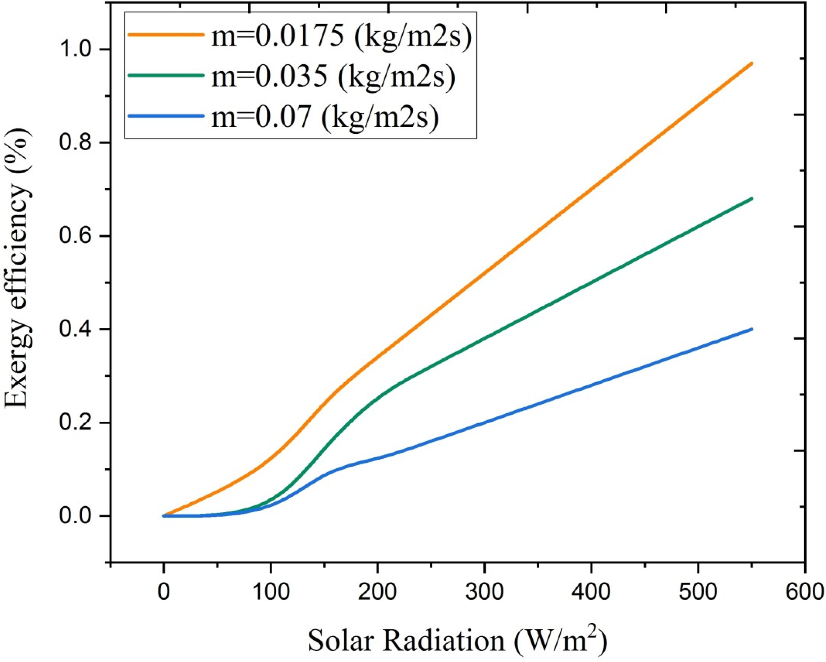
Changes in exergy efficiency according to solar radiation intensity for different mass flow rates (Hg).
This study investigated how changing the mass flow rate affects the thermal efficiency and exergy efficiency of an air heater. The results, shown in Figures 26 and 27, indicate that increasing the mass flow rate leads to a 16% improvement in thermal efficiency. However, the exergy efficiency decreases by approximately 40% as the mass flow rate increases. According to equation (17), there is a direct relationship between mass flow rate and thermal efficiency, meaning that as the mass flow rate increases, thermal efficiency also improves. On the other hand, an increase in mass flow rate results in higher entropy production, leading to more exergy destruction and a decrease in exergy efficiency, as shown in equation (27).
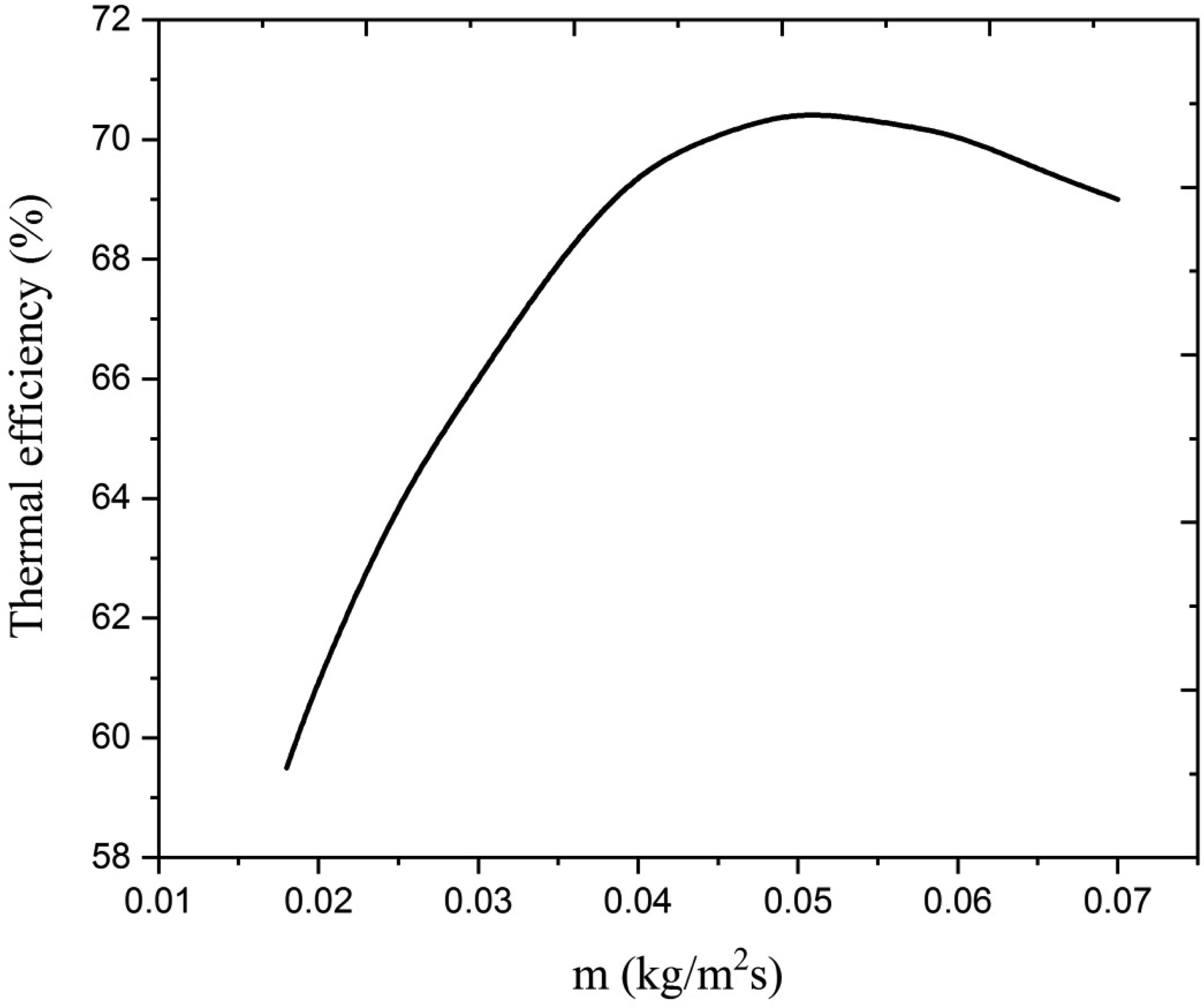
Changes in thermal efficiency according to different mass flow rates.
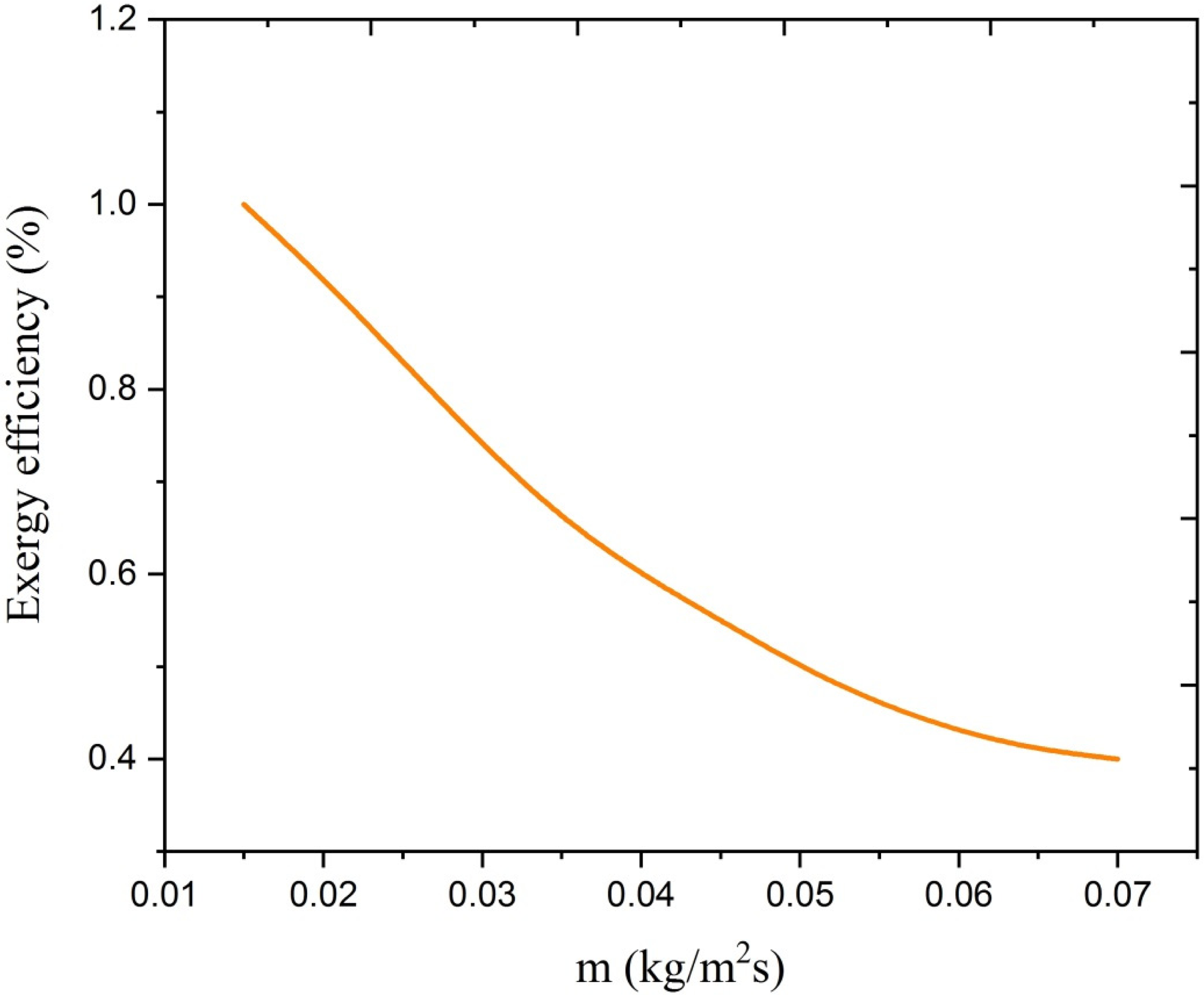
Changes in exergy efficiency according to different mass flow rates.
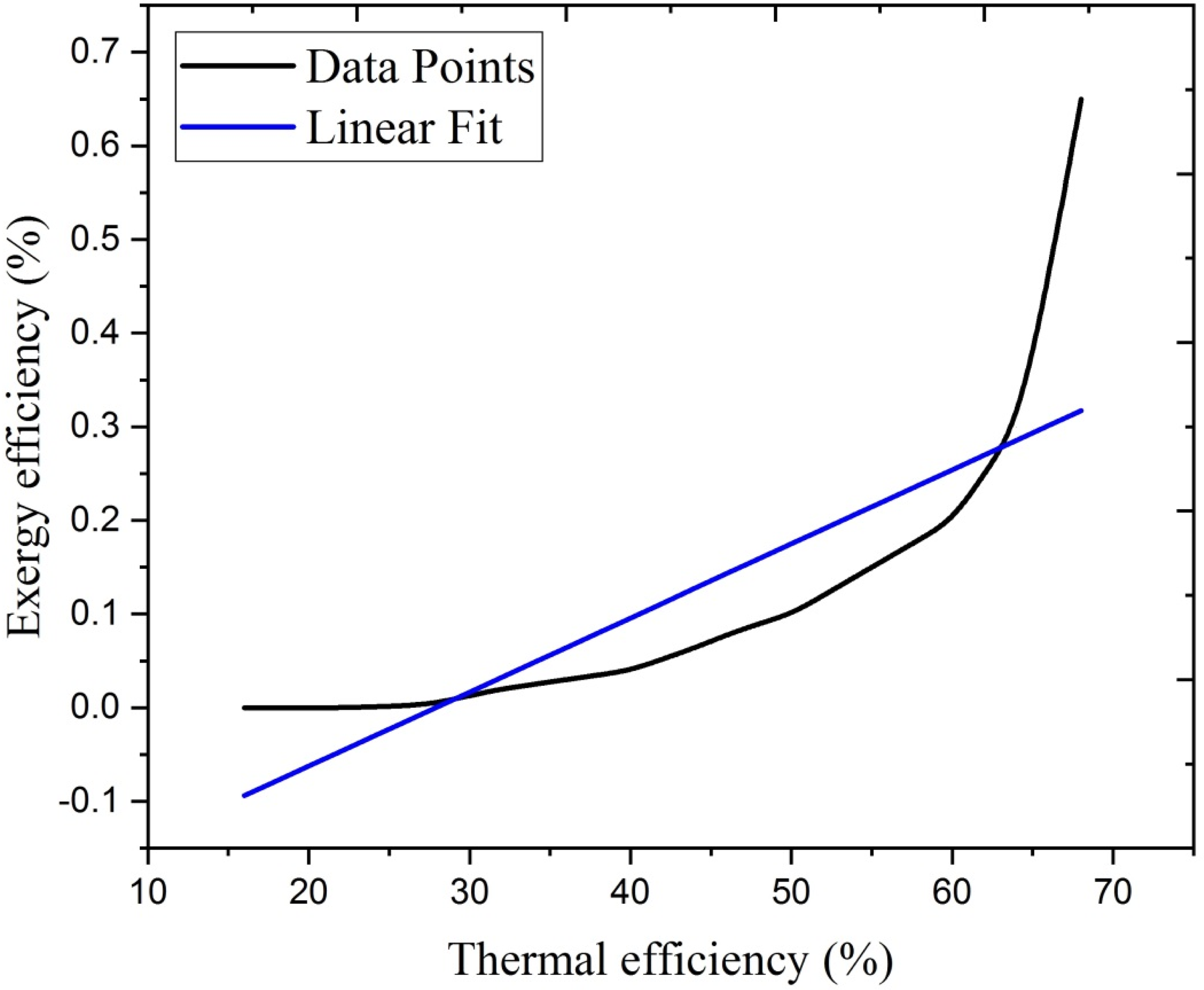
The graph in Figure 28 shows how exergy efficiency changes with thermal efficiency for the air heater at a maximum mass flow rate of 0.07 kg/m2s at different times of the day. It is clear that as thermal efficiency increases, exergy efficiency also increases. This means that as thermal efficiency gets better, the system destroys less exergy, resulting in higher exergy efficiency. Over the specified time period, thermal efficiency increases by around 4%, while exergy efficiency increases by about 16%. To quantify the observed relationship between thermal efficiency and exergy efficiency, a least-squares linear regression was conducted on the simulation data. The analysis revealed a very high coefficient of determination (R2 = 0.987), indicating that variations in exergy efficiency are closely explained by changes in thermal efficiency. The predicted values closely follow the simulated data, and the residuals show no systematic pattern, confirming the adequacy of the fit. This strong linearity implies that improvements in thermal efficiency under the studied operating conditions will generally be accompanied by proportional gains in exergy efficiency, reflecting consistent performance patterns across the range of simulated cases.
Changes in thermal efficiency in terms of exergy efficiency.
This proportional correlation between thermal and exergy efficiencies is consistent with trends reported in earlier works. For example, Ural (2019) observed that improved thermal efficiency in flat-plate solar air heaters with novel absorber materials was accompanied by proportional gains in exergy efficiency under steady-state conditions. Similarly, Raam Dheep and Sreekumar (2020) demonstrated a linear relationship between thermal and exergy efficiencies in parallel-flow solar air heaters, attributing the effect to simultaneous reductions in entropy generation with improved heat utilization. Comparable patterns have also been reported for advanced absorber geometries by Ma et al. (2020), who linked the dual improvement to enhanced convective heat transfer and reduced irreversibility in coupled air–solar collector systems. The present study confirms these earlier findings for serrated absorber designs, further illustrating that optimized geometry achieves thermohydraulic benefits without compromising the quality of energy output.
Table 4 presents the variation of friction factor (f), pressure drop (ΔP), and fan power requirements for the smooth absorber plate, the optimized serrated configuration (g/p = 0.15, h/p = 0.8), and a limiting-case serrated configuration (g/p = 0.05, h/p = 1.0), over Reynolds numbers between 5000 and 20,000. The results indicate that the baseline (smooth plate) exhibits the lowest f and ΔP values, as expected due to minimum surface roughness. Optimized serration increases f by ∼18% to 28% over the smooth case across the Re range, producing a proportionate increase in ΔP. The rise in fan power is modest (<15%) relative to smooth, while yielding significant heat-transfer enhancement.
Pressure drop and fan power analysis.
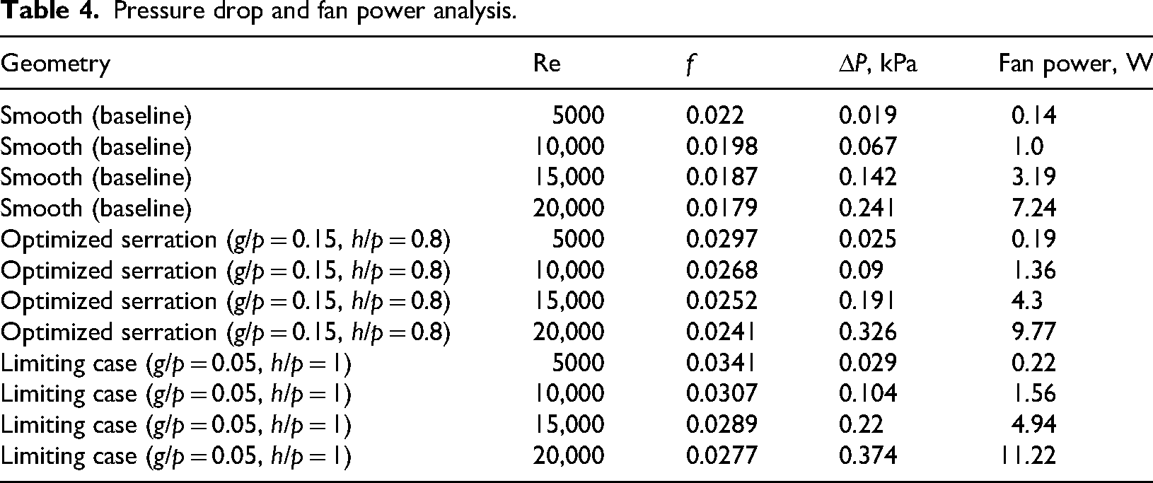
Limiting-case serration (high tooth height, very small gap) shows the largest pressure penalties: f increases up to ∼50% over smooth at low Re, with a corresponding ΔP and fan-power rise exceeding 40%. This configuration's thermodynamic gain is outweighed by the excessive pumping penalty, consistent with entropy-generation trends. The ΔP values scale nearly linearly with Re2, consistent with Darcy–Weisbach correlations, while fan power, calculated via equations using the measured f values, exhibits a similar scaling. These quantitative results clarify the penalty–benefit balance: moderate serrations (optimized case) provide an excellent heat-transfer benefit with tolerable pressure losses, while extreme serrations are detrimental from a net-exergy standpoint.
Practical implications and limitations
Beyond advancing the theoretical understanding, these results hold practical significance for the design of solar air heaters deployed in agricultural drying, space heating, and other renewable thermal applications. For instance, the identified optimal glass–absorber gap and serration geometry can inform collector designs that maximize energy yield during peak sun hours while avoiding excessive fan energy use—critical for off-grid or low-power systems in rural settings. The tradeoff curves between efficiency gains and pressure penalties can serve as direct inputs to technoeconomic sizing methods for dryers and space heaters. However, the study's steady-state, uniform-irradiance assumptions limit direct transfer to highly variable climates, and the model does not capture potential long-term factors such as surface soiling, absorber coating degradation, or seasonal thermal storage integration. Future investigations should extend this work via transient simulations, field-scale experiments under diverse climatic conditions, and incorporation of maintenance-related performance degradation to strengthen design reliability in practical contexts.
Economic and Practical Viability Considerations—although the present study did not undertake a dedicated quantitative economic analysis, the predicted thermal efficiency improvements of ∼9% to 11% and exergy efficiency gains of ∼18% to 21% relative to a smooth-plate baseline imply a proportionate enhancement in useful energy output for the same collector footprint. Literature reports (Prakash and Kamatchi, 2023; Singh et al., 2024) on serrated and finned collectors suggest that such gains could shorten typical payback periods by several months in agricultural drying and small-scale space heating applications, even when factoring in modest increases in fabrication cost due to additional forming processes. These manufacturing steps—usually roll-forming or stamping—are already standard in commercial collector production, making large-scale fabrication technically viable. The toothed geometry also improves plate stiffness, potentially extending service life. The main operational consideration is maintaining clean tooth surfaces in dusty environments to preserve performance. Based on these performance and durability factors, the proposed design appears economically and practically promising for medium- and large-scale implementations, pending future field trials that couple full-scale cost modeling with measured long-term performance.
Conclusion
The primary objective of this research was to develop and validate a coupled energy–exergy MATLAB model for a double-pass solar air heater fitted with a serrated absorber plate, and to quantify the combined impacts of geometric and operational parameters on performance. The hypothesis—that optimized serration geometry and appropriate gap sizing would enhance both thermal and exergy efficiency without incurring prohibitive pressure drop—was directly supported by the results. The validated model reproduced benchmark data with high accuracy, confirming its suitability for predictive analysis. Parametric studies showed that increasing the glass–absorber gap up to 10 cm improved thermal efficiency by ∼9% to 11% and exergy efficiency by ∼18% to 21%, aligning with the objective of identifying optimal geometric variables. Increasing mass flow rate improved thermal efficiency by up to 14% to 16% but reduced exergy efficiency by ∼38% to 40%, which supports the hypothesis of a tradeoff between heat transfer and irreversibility. Similarly, the analysis confirmed that serrated geometry enhances turbulence and heat transfer, but extreme serration parameters elevate pressure losses beyond net-benefit thresholds, validating the pressure-drop–heat-transfer balance objective.
These findings collectively achieve the stated aims: (i) providing a rigorously validated, design-ready simulation tool; (ii) delivering quantitative insights on the interplay of operational and geometric parameters; and (iii) offering optimizable design ranges for high-performance renewable thermal applications. Future work may incorporate transient effects and experimental extensions to broaden applicability.
Footnotes
Funding
The authors received no financial support for the research, authorship, and/or publication of this article.
Declaration of conflicting interests
The authors declared no potential conflicts of interest with respect to the research, authorship, and/or publication of this article.