
Abstract
To improve the recovery rate of thin coal seams under complex geological conditions and to investigate overburden failure and migration during pillarless mining, a study was conducted at a fully mechanized coal mining face in the Yuwang Coal Mine. Based on key strata theory and the “110” mining method, the research integrated theoretical analysis, physical similarity experiments, and numerical simulations. Strain and infrared monitoring systems were used to observe the deformation characteristics of the overlying and surrounding rocks in the roadways during roof cutting and pressure relief. Monitoring focused on two aspects: the displacement field and the temperature field. The study optimized roof cutting parameters for thin coal seam working faces in complex geological settings and proposed a surrounding rock control technique for gob-side entry retention, based on mine pressure monitoring data. Results indicate that the roof cutting angle significantly affects roof movement. Optimal conditions for minimal roof displacement and subsidence were observed at a cutting angle of 75°and an average cutting height of 7 m. Asymmetric movement of the overburden was observed on both sides of the cutting seam, with a short-arm beam structure forming upon roof cutting, which helped slow the overburden movement. Preferential collapse occurred on the cutting seam side, resulting in greater subsidence displacement compared to the non-cutting side, thereby relieving roof pressure. The implementation of the “cutting roof pressure relief NPR cable stress compensation” technique effectively addresses the stability issues of surrounding rock in pillarless mining by mitigating roof pressure through controlled roof cutting.
Keywords
Introduction
Coal, as a cornerstone of China's energy sector, is projected to maintain its dominant role in national energy consumption over the next three decades (Yan et al., 2013; Ye et al., 2018; Zhao et al., 2023). As coal seam mining continues to advance, there is an increasing necessity to widen reserved coal pillars to uphold the stability of adjacent rock strata and supporting structures. This requirement becomes particularly critical in the extraction of thin coal seams under complex geological conditions, where the use of wider coal pillars can lead to significant wastage of valuable coal resources (Guan et al., 2017; Guo et al., 2023; Zhao et al., 2011).
The traditional mining method is the one that involves leaving coal pillars. This method not only wastes coal resources but also is prone to cause dynamic disasters in the coal pillars or adjacent tunnels. Domestic and foreign scholars have conducted numerous studies on rock masses with joint fractures. In terms of laboratory experiments: Tang and Song (2019) conducted research on the joint inclination angles and concluded that when the inclination angle is large, the rock has obvious brittle properties. In terms of theoretical analysis: Zhou et al. (2020) proposed a new algorithm for extracting and segmenting joint fractures by studying the distribution characteristics of joint fractures within the rock; Shen (1994) proposed the F criterion based on the G criterion. With the continuous development of computer technology, numerical simulation techniques such as finite-element method, boundary element method, and finite-difference method have continuously been integrated into engineering application analysis (Wang et al., 2025). They visually analyzed the stability of the slopes using on-site data. Feng et al. (1986) evaluated the regional engineering geological zoning for stability using the fuzzy comprehensive evaluation method. They determined the instability of the slopes through the comprehensive factors of multiple indicators. Meng et al. (2025) conducted an engineering geological zoning evaluation using the GIS method, combining the GIS platform with mathematical methods to analyze the stability of the surrounding rocks. Dong et al. (2022) utilized travel time tomography technology to identify abnormal areas in rock masses, providing new insights for the safety and stability of rock masses. Wu et al. (2022; 2023) determined the stiffness of yield lining by studying the hardening characteristics of shotcrete.
In 2009, Academician He Manchao innovatively developed the negative Poisson's ratio (NPR) anchor cable and introduced the concept of roof cutting for pressure relief. This innovation capitalized on the fragmentation of the roof and expansion of the roadway, as the mechanical compensation effect of the NPR anchor cable shifted stress concentrations away from the roadway. This breakthrough led to the development of the “110” mining method, which effectively addresses support costs and material-related challenges (He et al., 2018a, 2018b, 2023). The 110 method utilizes directional drilling and blasting techniques to precisely cut the roof of the mined-out area, cutting off the pressure transmission of the roof rock mass, forming a “stress isolation zone,” thereby avoiding the damage to the roadway caused by mining-induced pressure. Through roof cutting for pressure relief and the support of NPR anchor cables, the roadway is maintained intact.
Wang et al. (2018a) found that the 110 mining method, by optimizing the mining layout, increases the minimum principal stress of the rock mass while reducing the maximum principal stress. This ensures that the Mohr stress circle of the rock mass remains well below the damage envelope, thereby significantly reducing the risk of rock failure and surface collapse and improving overall rock mass stability. Ma et al. (2023a) demonstrated the effectiveness of the 110 mining method by comparing the full compression-collapse process of the rock mass under both the traditional 121 method and the 110 method. Their findings confirmed the 110 method's advantages in controlling rock deformation and mitigating surface subsidence. By reducing overburden deformation in mining areas, the 110 method plays a crucial role in maintaining underground space stability.
Additional research has further reinforced the theoretical and practical foundation of the 110 method. Zhang et al. (2024) studied overburden damage from an energy perspective, providing guidance for stope parameter design. Guo et al. (2024) proposed the “combined simply supported beam” and “masonry beam” models to address coordinated mine pressure control in extra-thick coal seam mining. Du et al. (2021) utilized optical fiber technology in model experiments to study the development of water-conducting fracture zones, offering a novel monitoring approach. Li (2023) examined surface settlement caused by short-distance coal seam mining using physical and numerical simulations, corroborated with field data. Ge et al. (2023) using FLAC3D simulation, found that continuous mining of very closely spaced coal seams poses greater technical challenges than single-seam mining due to intensified stress interference—an essential factor in thick seam pressure control. Wang et al. (2023) identified roof movement patterns in self-contained roadways without coal pillars using structural mechanics models. Yang et al. (2019) analyzed the deformation patterns of the basic roof rock mass through numerical simulation. At present, research on the 110 mining method's roof cutting and pressure relief techniques mainly focuses on roadway formation mechanisms and the mechanical behavior of support structures (Sun et al., 2024; 2025; Wang et al., 2013). However, roof-cutting and pressure-relief mining without coal pillars remain in the stage of technical exploration, particularly under complex geological conditions (Han et al., 2022; Ma et al., 2023b; Ning et al., 2013).
Building upon this context, the present study—carried out at the Yuwang Coal Mine—employs physical similarity experiments and numerical simulations to explore the performance of the NPR active support system. Specifically, it investigates changes in the temperature field, stress–strain field, and displacement field during the roof-cutting and pressure-relief process in a pillarless mining setup. The aim is to provide theoretical support for implementing the 110 mining method in thin coal seams under complex geological conditions.
Engineering background
The Yuwang Coal Mine is located in the southwestern part of the No. 4 Exploration Area within the Laochang Mining District of Fuyuan County. The fully mechanized working face, designated 1010201, operates at depths ranging from 465 to 600 m. It spans 215 m along the strike and 207 m along the dip. The entire long-arm strike is mined simultaneously, focusing on the extraction of the C2 coal seam.
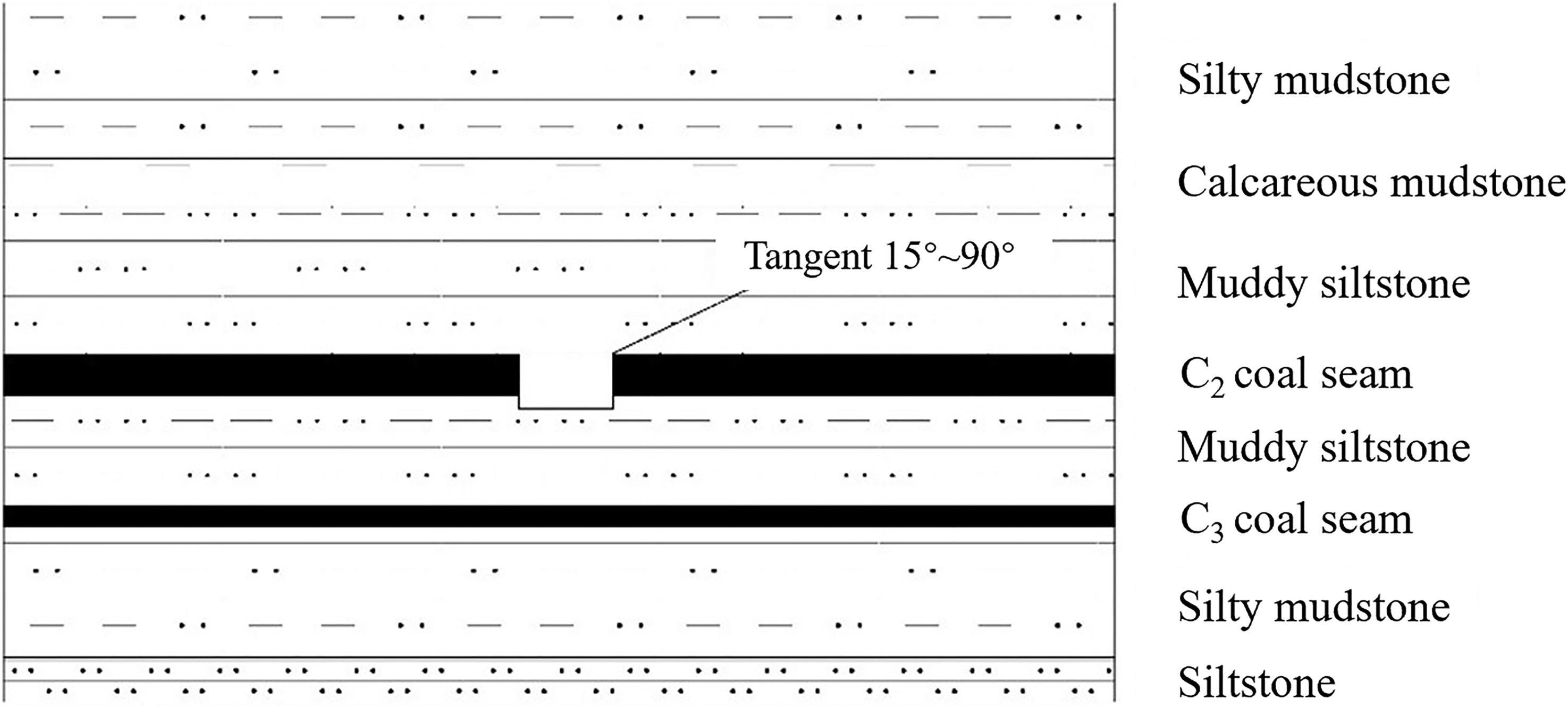
The C2 coal seam has a dip angle between 5° and 12° and a mining height of 1.3 m. Both the roof and floor of the seam are composed of siltstone, as illustrated in Figure 1. The working face revealed significant geological complexity, with 31 faults exhibiting vertical displacements greater than 1 m. Among these, two faults had displacements exceeding 50 m, and one fault exhibited a throw between 20 and 50 m. The faults included 28 normal faults, two reverse faults, and one fold, reflecting the challenging geological conditions of the mining area.
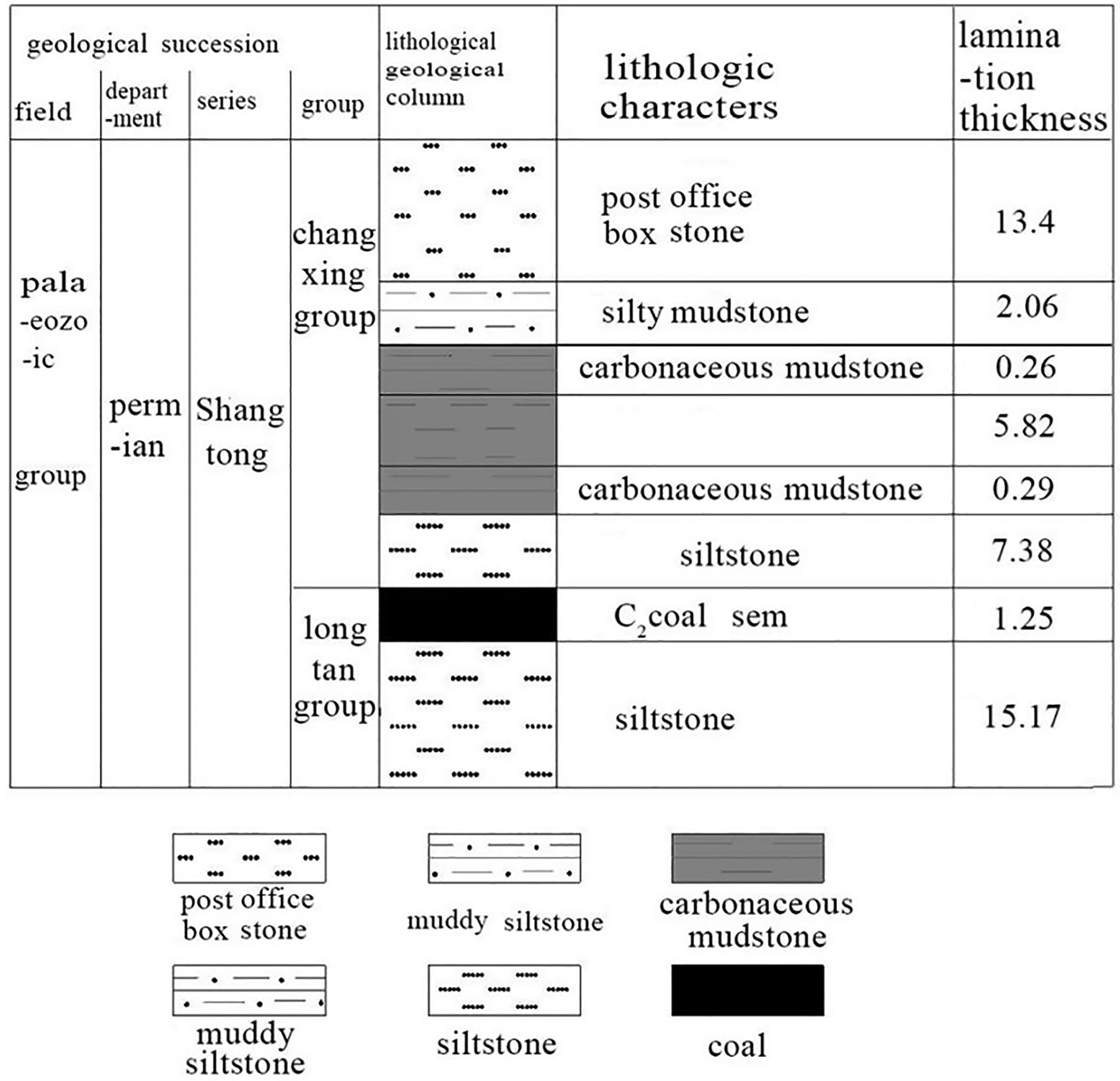
Histogram of the stratigraphic composite.
“110” theory of work methods
The 110 mining method is an innovative mining technique developed by the academician He Manchao, based on the theory of roof cutting and arm beam shortening (He et al., 2016; Ji, 2025; Wang et al., 2024). This methodology involves advancing the working face between two roadways without leaving the coal pillars. Initially, NPR anchor cables were used to reinforce the roadway roof.
This was followed by directional blasting at the top of the mining side to induce pre-cracking and cutting (Miao et al., 2022; Peng et al., 2015; Qian et al., 2018; Wang et al., 2018b). This process severed the stress transmission between the roadway and the goaf roofs, prompting the premature collapse of the overlying strata in the goaf. The resulting caving gangue formed a gangue slope along the goaf-retaining roadway. The fragmentation properties of the gangue facilitate the filling of the operating face, effective support is provided to the overlying strata, and successful retention of the roadway is ensured (Xia et al., 2021). As shown in Figure 2, the 110 mining method was based on a specific operational principle (Xue et al., 2023; Yan et al., 2016; Yang et al., 2020).
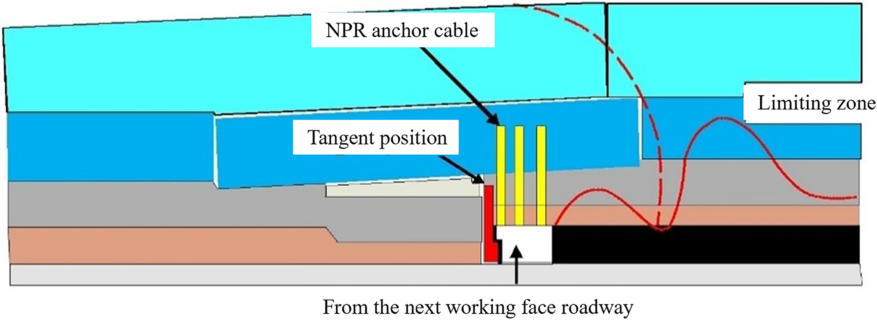
“110” Principle of construction method.
The 110 mining method is based on the principle of offsetting the dynamic pressure exerted by the roadway roof to minimize the deformation of the surrounding rock mass. The NRP cable exhibited an NPR effect (Figure 3), maintaining its Poisson’s ratio without necking or notable reduction, making it well-suited for effectively controlling large deformations in the tunnel surrounding rock. The strength of ordinary anchor cables is insufficient, and they are prone to breakage during the supporting process. The mechanical response of an NRP cable is primarily manifested in three stages: elastic material deformation, structural deformation, and ultimate deformation (Zhu, 2019; Zhu et al., 2025).
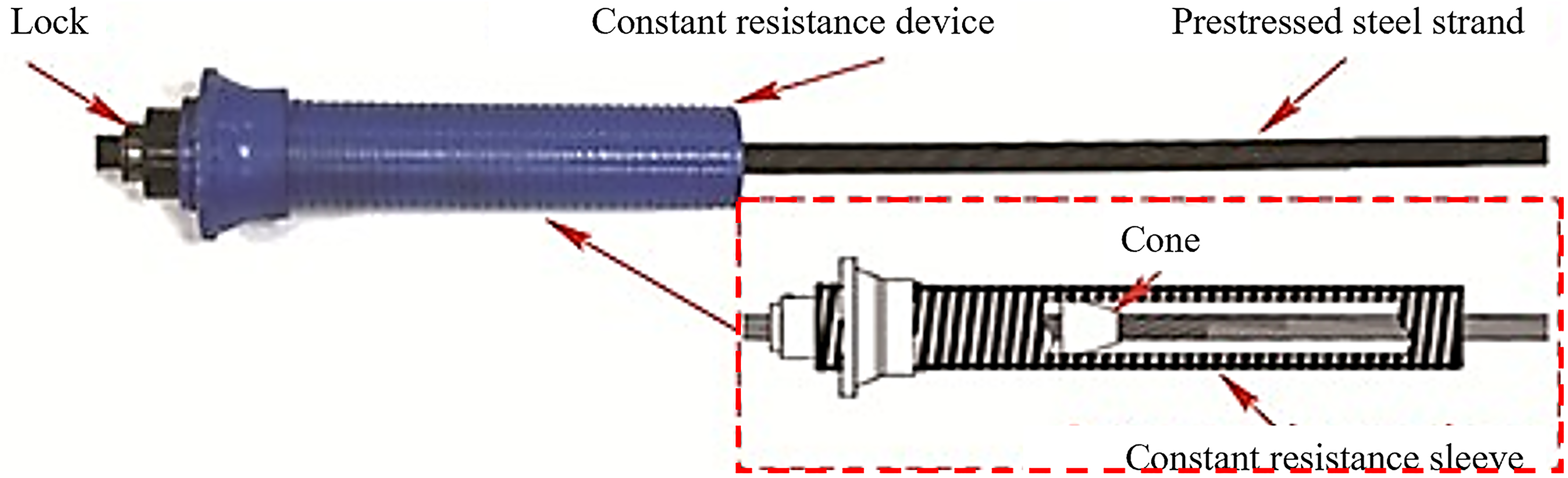
Structural diagram of the NPR anchors.
Modeling the structural evolution of the roof slab along a hollow tunnel with a cut roof
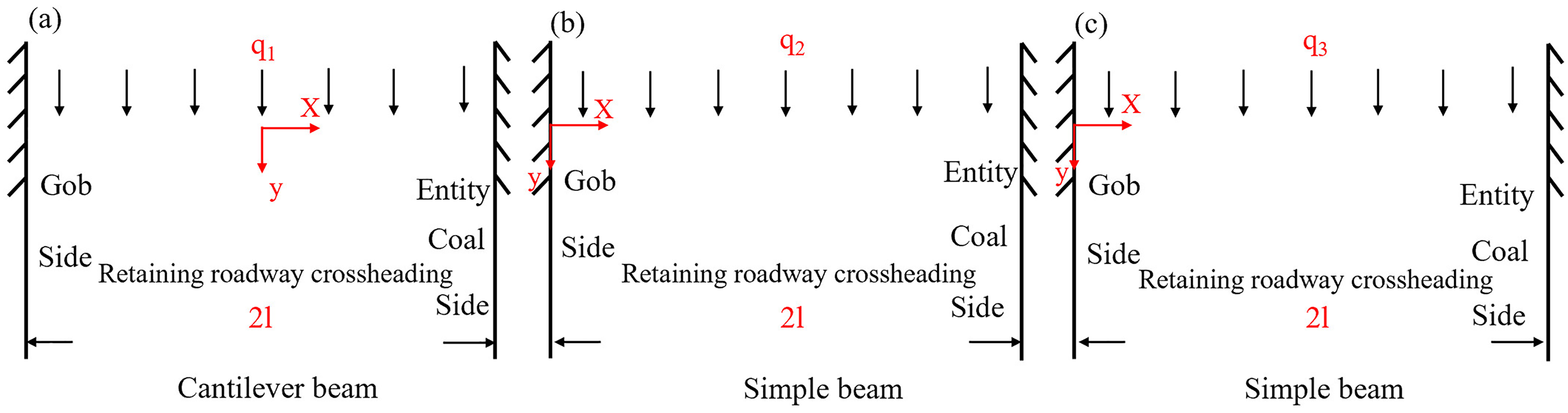
The evolution of the roof and roadway-side hinge structures in the goaf-retaining roadway can be divided into three main zones: the working face leading area, the dynamic pressure area, and the stable area of the roadway section (Ji 2025; Peng et al., 2015). In this model, the roadway width is denoted as 2l, the height of the key stratum as h, and the equivalent load acting on the roof as q1. The roof rock beam serves as the reference point, with the x-axis aligned parallel to the roof and the y-axis oriented vertically. Figure 4 depicts the progression of the mechanical model of the roof at the working face.
The roof slab in the overrun zone of the working face was kept stable under the fixed support of the supporting structure. The deflection vc of the key beam of the roof slab was calculated using the following formula:
where vc is the deflection of the key beam of the roof plate (m); E is the elastic modulus of the key beam (MPa); q1 is the equivalent load of the roof plate (MPa); x is the axial displacement (m); h is the height of the key beam of the roof plate (m); and 2l is the width of the roadway (m). The deflection of the key beam in the middle of the roadway (x = 0) was the largest and was prone to tensile damage.

Mechanical model of the top plate in the ahead zone (modified after Ji, 2025; Peng et al., 2015).
Equation (1) shows that the deflection in the middle of the roadway (x = 0) is the largest and is prone to tensile damage, and the two-arm support structure of the roadway can maintain its stability.
The dynamic pressure zone is the stage of roof collapse and sinking after cutting the roof, and the roof plate in this zone is in the hanging wall beam structure. The deflection of the key beam of the roof plate knot vd is calculated as follows:
where vd is the deflection of the dynamic pressure zone (mm), q2 is the equivalent load of the roof plate in the dynamic pressure zone (MPa), and the remaining symbols are the same as above.
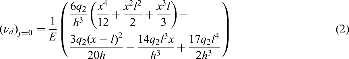
From Equation (2), the maximum deflection of the roof plate (x = 1) is located at the end of the hanging wall beam on the mining side, and effective countermeasures should be taken when leaving the roadway.
The stabilization zone of the tunnel is located behind the dynamic pressure zone, and the rock collapsed from the cut roof has a certain bearing capacity; the key beam in this zone can be simplified into a “simply supported beam structure.” The key beam deflection vw is calculated as follows:
where q3 is the equivalent load on the roof plate (MPa), and the rest are the same as above.
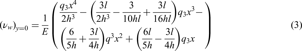
The stabilized zone of the tunnel formation forms a new balanced structure under the support of the compaction of the hollow zone, and the stability is improved. The stability of the surrounding rock in a cut-top lane is closely related to lane-formation zoning.
Experimental scheme
Numerical simulation of slit angles
A geological model for retaining roadways in the goaf of No. 1010201 working face at the Yuwang Coal Mine was established based on geomechanical parameters. This study investigated the displacement characteristics of the surrounding rock under varying roof cutting angles by simulating an overburden load of 9 MPa at the actual buried depth.
Numerical simulation scheme and steps
(1) Geological model
Geological model: A model with dimensions of 50 m × 5 m × 32 m, including a roadway measuring 5 m × 5 m × 3 m. The model incorporated support NPR anchor cables (9 m long) on the roof.
(2) Numerical simulation
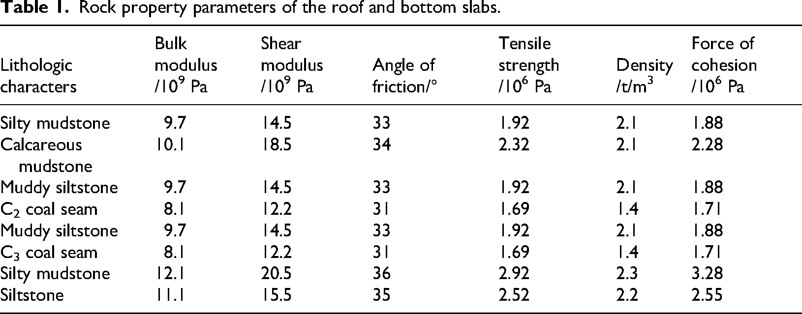
Numerical simulation: The FLAC3D software was used to confine the bottom and periphery of the geological models. A vertical load of 9 MPa is applied to the roof. The simulation investigated the roof displacement behavior under varying slit lengths (7 m) and angles (15°, 30°, 45°, 60°, 75°, and 90°), providing a foundation for the execution of physical model experiments. As shown in Figure 5, Table 1 lists the mechanical properties of the formation.
Schematic of the numerical simulation model.
Rock property parameters of the roof and bottom slabs.
Simulation results of the top-cutting angle
As shown in Figures 6 and 7, a cutting joint angle below 45° results in a significant displacement above the joint, with a mean value of approximately 4.89 × 10⁻⁵ m. Conversely, when the cutting joint angle exceeds 45° and approaches 90°, the displacement gradually decreases to approximately 4.79 × 10⁻⁵ m. Alignment with the right side of the roadway occurs at a 90° cutting joint angle, resulting in narrowing of the extent of the collapse of the air-sealed area to the right of the cut, which prevents the expansion of the collapse of the rock mass. For cutting joint angles of 60° and 75°, the maximum displacement was observed at a 75° angle, measuring approximately 4.7 × 10⁻⁵ m. As illustrated in 6 and 7, the displacement in the X-direction was minimal at a cutting joint angle of 75°, indicating that 75° represents the optimal angle for the kerf (Huo et al., 2024).
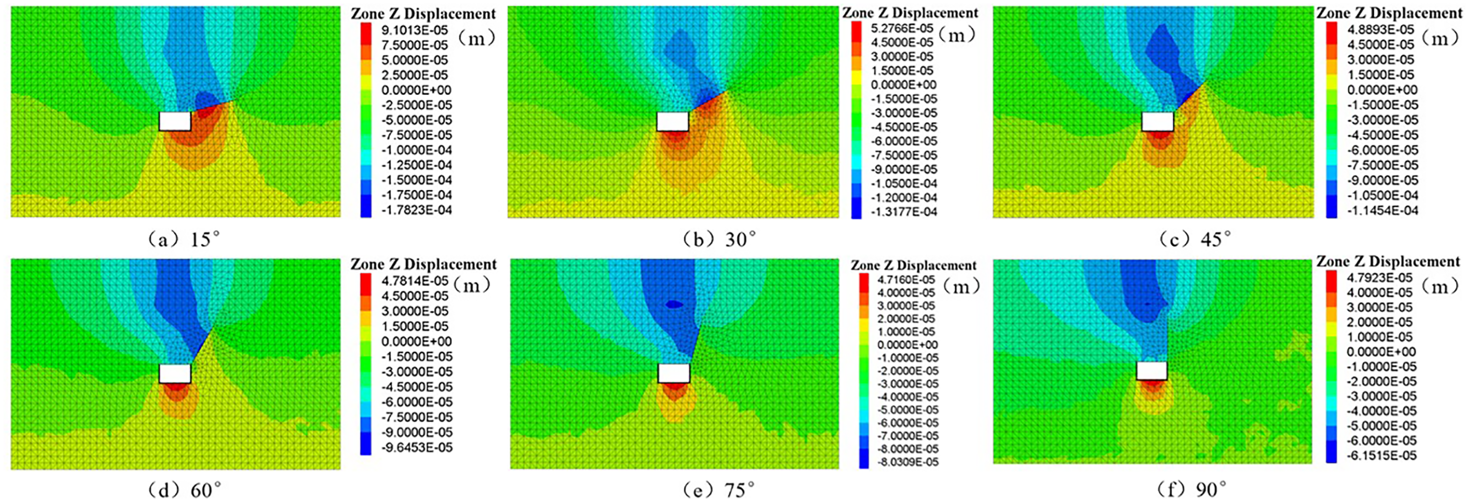
Variation in cloud maps in the Z-direction of the rock body at different angles.
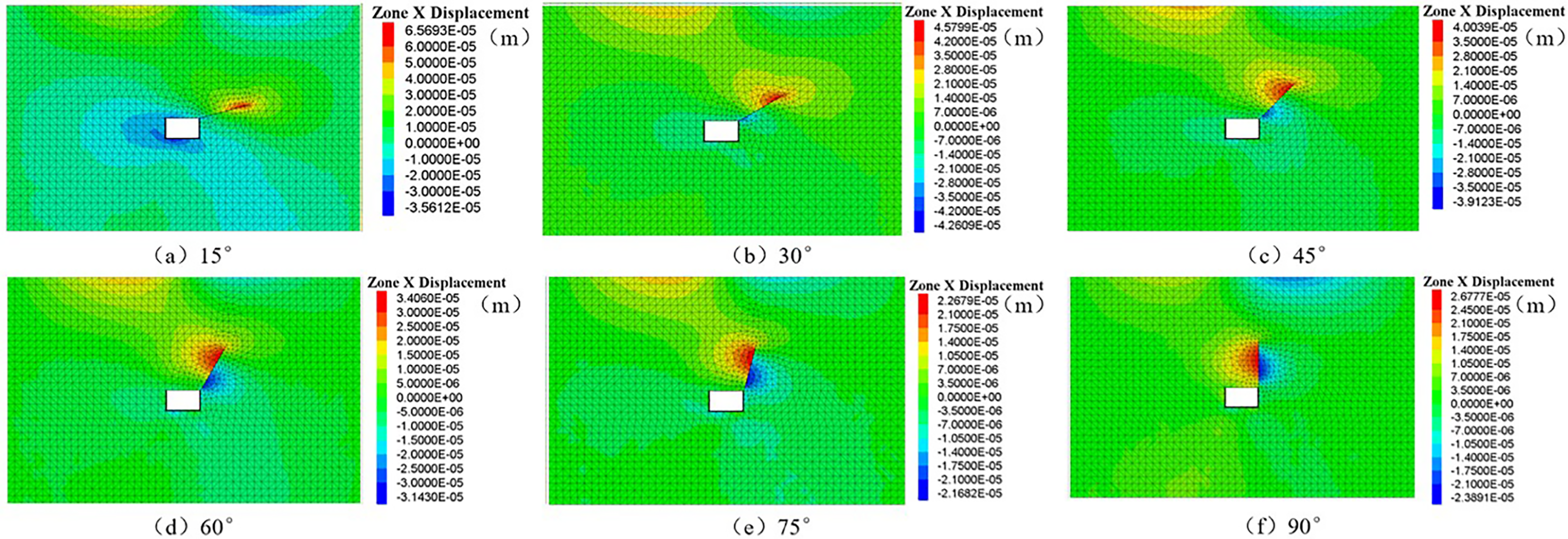
Variation in the X-direction displacement of the rock mass under different slit angles.
Physical simulation experiment of cutting top and staying lane
Based on the optimal angle determined from the numerical simulations, a physical experiment was conducted to simulate roof cutting and pressure relief.
The experimental setup employed a physical model test system designed to simulate the failure processes of deep soft-rock roadways (Li et al., 2023a, 2023b). This experiment was conducted using a three-dimensional physical pressure model. This system consists of a main structural unit, a hydraulic control console, and ancillary components, allowing for both continuous and discontinuous loading conditions. The monitoring system included digital image correlation (DIC) to track the movement patterns of the overlying rock mass above the excavated coal seam, an infrared thermal imaging system, and instruments for stress–strain data acquisition, such as strain gauges and earth pressure boxes. The similarity scale of the experiment was set at 1:50, as shown in Figure 8.
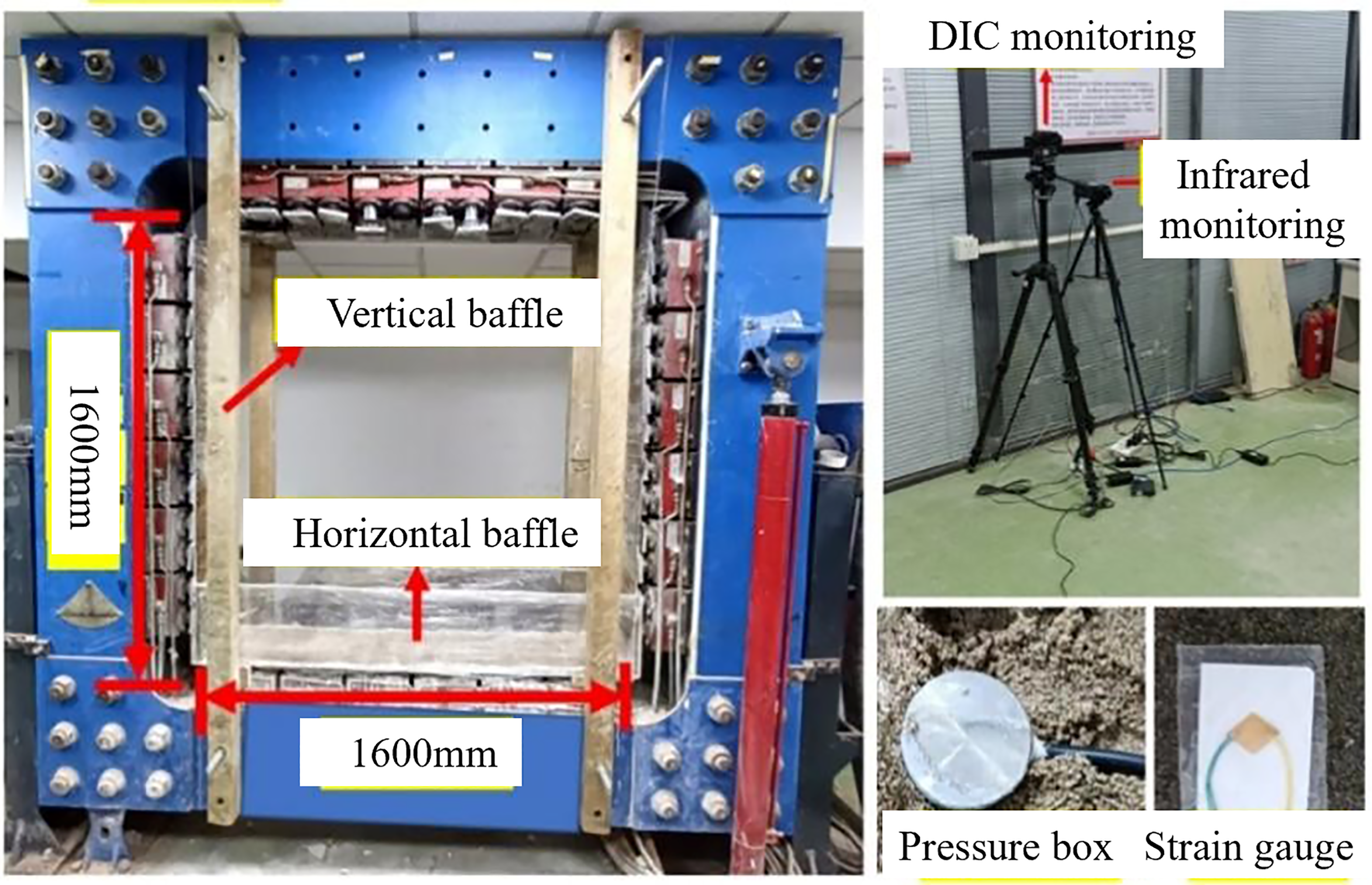
Test and monitoring equipment.
The NPR anchor cable design followed a proportional scaling scheme. Initially, static tensile tests were conducted on full-scale macro NPR anchor cables using a static tensile testing machine, yielding an actual ultimate tensile resistance of 350 kN. Subsequently, static tensile testing was performed on 3D-printed NPR anchor cables using a small indoor tensile machine. A physical model test using six of these 3D-printed NPR anchor cables—each subjected to a load of approximately 60 N—was carried out.
The model excavation proceeded from right to left along the coal seam roof in the C2 seam area. Displacements of the roof on both sides of the roadway were monitored throughout the process, as illustrated in Figure 9.
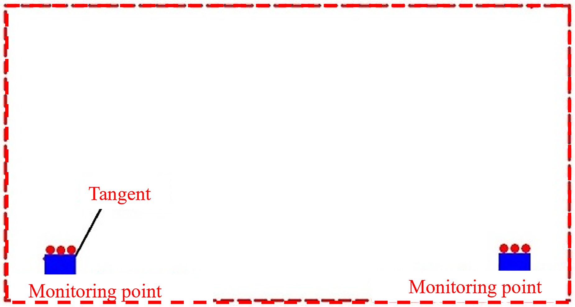
Layout of monitoring points.
As demonstrated by the engineering geological data, the burial depth of the C2 coal seam is precisely 470 m. σv is 11.2 MPa, σh is 15 MPa, the initial σv of the model is set to 0.1 MPa, and σh is 0.2 MPa, according to the stress similarity ratio. The loading process, as depicted in Figure 10, was carried out in stages. In the initial stage, two steps were employed to load the model to its original rock stress state, with a loading gradient of 0.05 MPa. Following pressure stabilization for a designated period, roadway and working face excavation was conducted in Stage B. The duration of pressure stabilization was approximately 15 min for each loading step.
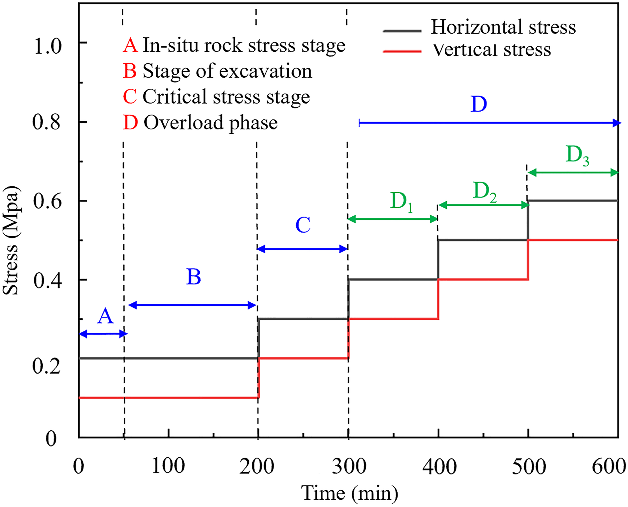
Stress loading path.
Stages C and D included the loading process designed to simulate the deformation and failure characteristics of the 110 mining method under varying stress conditions. It is evident that the simulated pressurization in Stage C corresponds to the actual formation pressure. Furthermore, the simulated burial depth is 470 m. In Stage D, the stress conditions were increased as follows:
Results and discussion
Stress–strain analysis
To simulate the slit, a plastic sheet was inserted into the model at the designated slit angle and then removed during the experiment. The stress and strain monitoring results are presented in Figure 11. Displacement measurements near the slit were noticeably lower than those in the area without a slit. Analysis revealed that displacement was more pronounced near the working face, indicating that the overlying rock mass experienced more intense movement in this region, while displacement in more distant areas was more gradual (Li et al., 2023a).
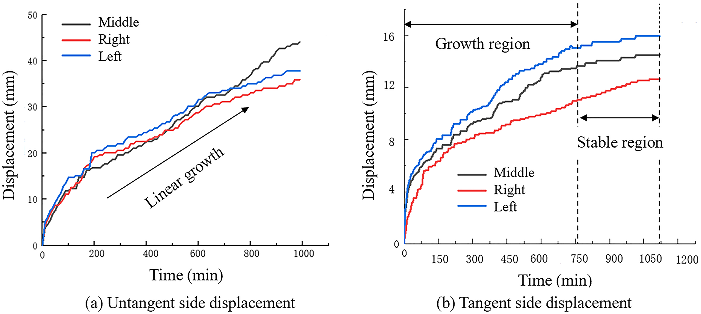
Monitoring displacement curves.
The maximum displacement on the non-slit side measured approximately 46 mm, whereas on the slit side, it was only about 16 mm. This observation highlights the significant role of slits in limiting deformation of the surrounding bedrock.
A comparison of the empirical data revealed a substantial reduction in maximum displacement due to the presence of the notch, thereby enhancing overall stability. This finding holds important implications for guiding the selection and design of reinforcement measures for surrounding rock in practical engineering. Such insights can help engineers more effectively manage and reduce surrounding rock deformation, thus improving project safety and stability.
In conclusion, the notch, as a simple and efficient reinforcement measure, demonstrated a notable ability to restrain surrounding rock deformation, warranting further research and application.
Analysis of DIC displacement monitoring results
Figure 12 illustrates the collapse behavior of the model, which can be categorized into two distinct types: direct collapse and basic collapse. In the model, direct roof collapse refers to the failure of the rock mass that forms a collapse zone. In contrast, basic roof collapse primarily involves the development of fractures, forming what is known as the fracture zone, characterized by a relatively extensive fracture network (Li et al., 2023a).
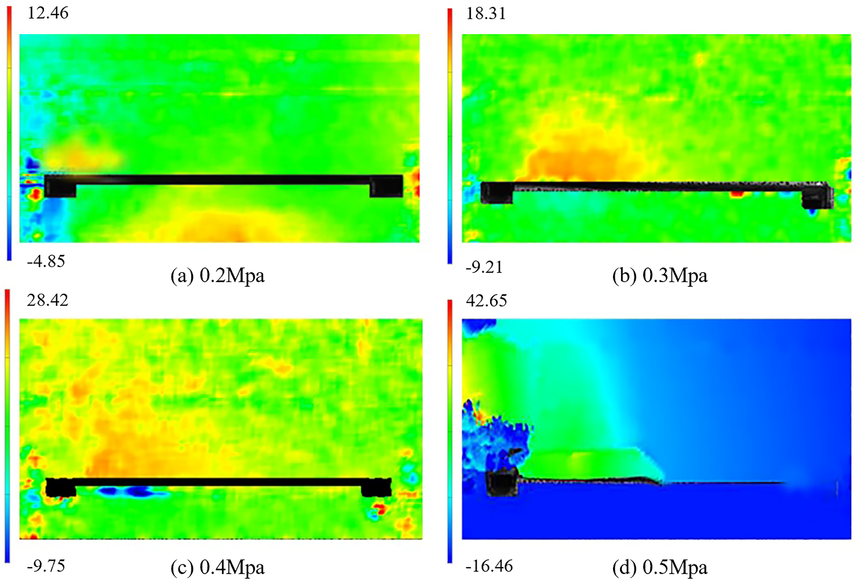
Speckle monitoring vertical displacement imaging diagram.
Displacement and subsidence on the slit side were notably greater than those on the non-slit side. Specifically, at a vertical stress σv of 0.2 MPa, the greatest overburden displacement occurred near the left kerf, reaching approximately 12 mm. When σv was set to 0.3 MPa, displacement became concentrated on the right side of the slit, with a maximum displacement of around 17 mm, accompanied by the onset of localized collapse. The reason for this phenomenon is that the existence of the tangent line interrupts the transmission of stress, causing the surrounding rock to undergo asymmetric failure.
With further increases in vertical stress—from 0.4 to 0.5 MPa—the direct roof transitioned from partial to extensive collapse. The fractured side of the slit exhibited improved filling capacity due to enhanced fracture propagation. As the direct roof delaminated, large cracks appeared in the basic roof, and greater displacement was observed on the left side of the roof compared to the right.
In summary, the immediate collapse of the roof occurred primarily after the slit was cut, followed by the subsequent collapse of the underlying roof, accompanied by extensive fracturing. The greatest displacement and subsidence were observed in the central-left area, followed by the cutting (slit) area, with the non-cutting side experiencing the least displacement. This behavior is mainly attributed to the fragmentation and expansion of the rock mass.
The goaf-filling process was initiated upon the collapse of the immediate roof on the cutting side, resulting in substantial early-stage displacement and negligible displacement in the later stages. This was followed by gradual settling of the underlying roof.
Analysis of the temperature field infrared monitoring results
Following roof cutting and pressure relief, deformation, fracturing, and movement of the overburden result in the formation of collapse and fracture zones, which in turn cause changes in the temperature field. In this experiment, infrared imaging was used to observe temperature variations in the region above the roadway and goaf. As shown in Figure 13, red and yellow hues indicate high-temperature areas, corresponding to high-stress zones, whereas dark blue and light blue shades represent cooler, low-stress regions (Li et al., 2023a).
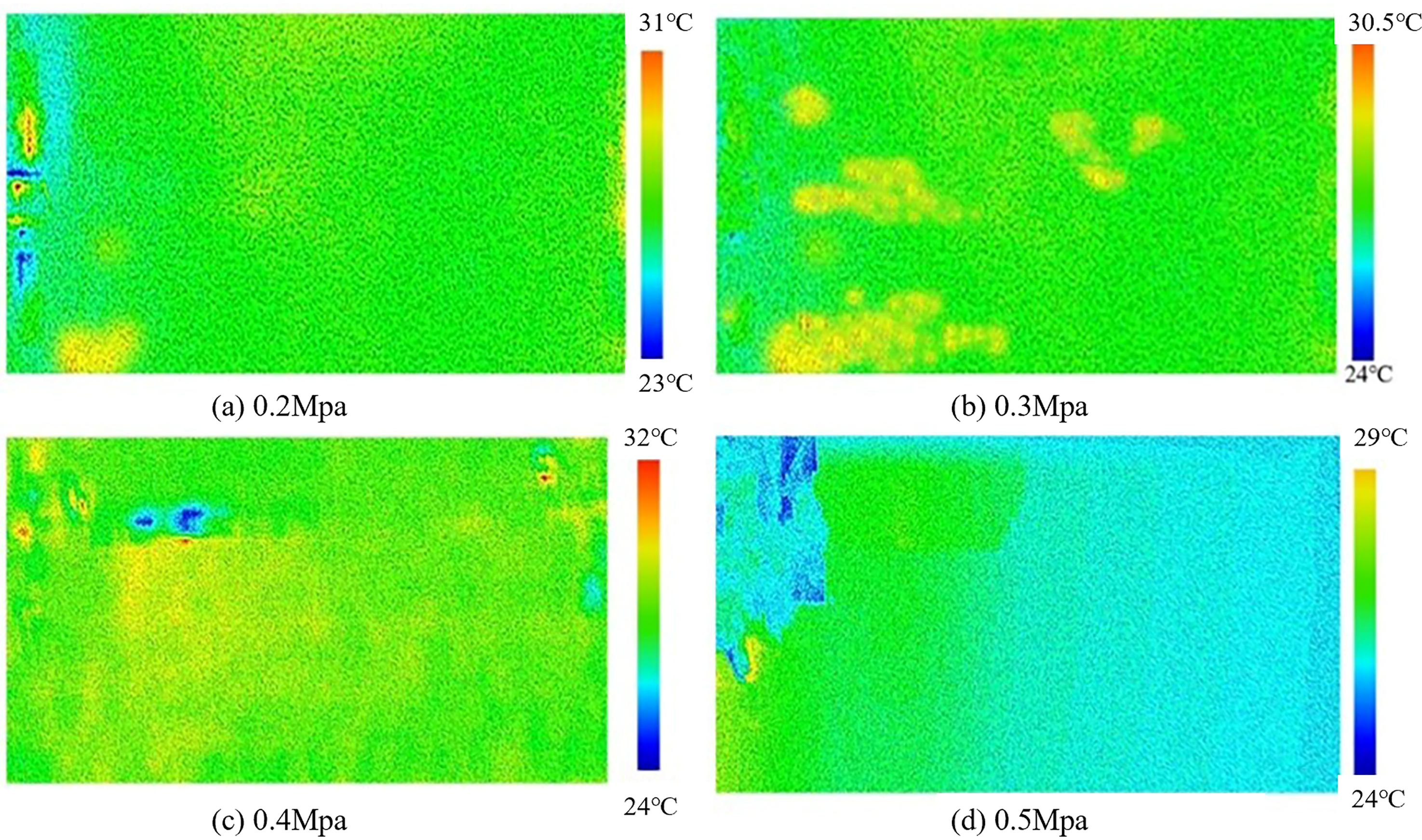
Temperature field monitoring diagram.
Subsequent to the excavation of the roadway and working face, a high-temperature zone was observed, predominantly located on the cut seam side. This is attributable to frictional sliding caused by shear stress at the seam. As pressure increased, the high-temperature zone gradually expanded. During this stage—characterized by the development of a fracture zone—the overlying rock mass remained largely intact.
It has been shown that continued pressure increases eventually lead to roof collapse. At a vertical stress of 0.5 MPa, partial collapse occurred, with the upper-left area clearly showing signs of rock mass failure, as indicated by lower surface temperatures. In contrast, the high-temperature zones in the middle and right sections showed less pronounced collapse. In these areas, the middle strata tended to collapse vertically or experienced minimal displacement, resulting in lower levels of friction and heat generation compared to the left side.
Motion analysis of asymmetric structures in overlying rock layers
Figure 14 illustrates that following roof cutting and pressure relief, the phenomenon of overburden movement follows the behavior predicted by the asymmetric structure model (Li et al., 2023a). The movement process can be divided into four distinct stages: ① NPR cable super-support process for the roof; ② Direct roof caving without compaction; ③ Basic roof fracture failure; ④ Progressive development of the fracture zone leading to gangue cave-in and effective filling on the cut seam side. At a vertical load of 0.2 MPa, local collapse occurred at the notch, with minimal overall roof displacement. When the vertical load increased to 0.3 MPa, localized collapse of the immediate roof strata took place at the seam, leading to an uncompacted working face. At 0.4 MPa, collapse of the basic roof on the left side was observed, accompanied by noticeable layering and separation near the direct roof, along with crack development in the upper rock mass—more pronounced on the left side than the right. Increasing the load further to 0.5 MPa caused continued collapse of the left-side basic roof and further crack propagation, again more concentrated on the left. At this point, the NPR anchor cable became exposed.
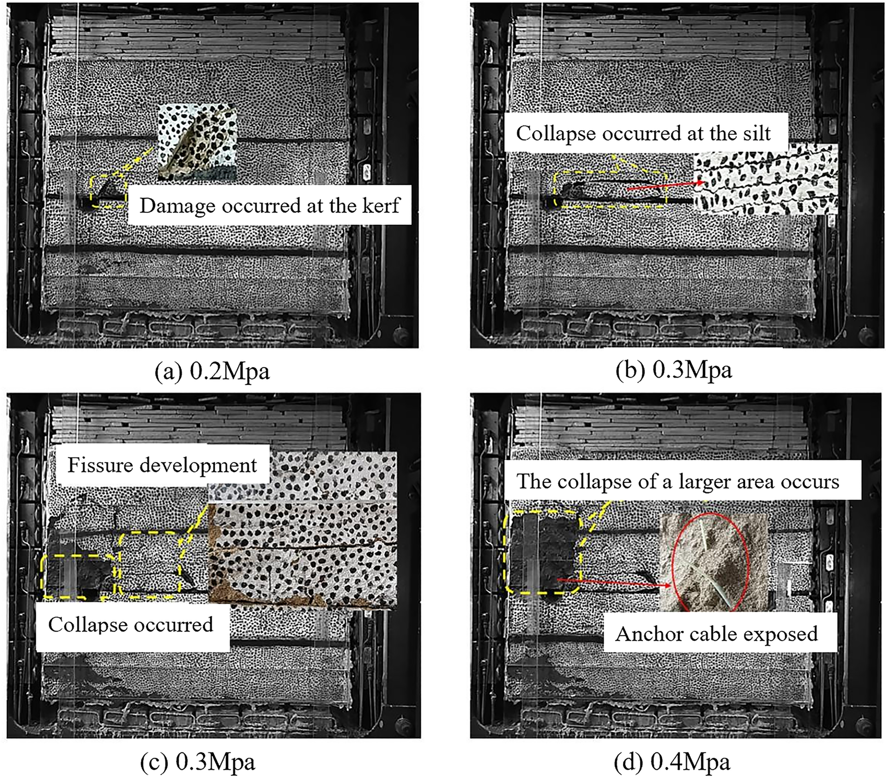
Motion diagram of the pressure model.
Nevertheless, there was a marked preservation of structural integrity: the rock mass between the uppermost point of the roadway roof and the lowest point of the NPR support zone remained largely intact, demonstrating the effectiveness of the support system. The internal structure of the rock mass in this zone showed a degree of stability.
In summary, the 110 mining method exhibits distinct characteristics of asymmetrical motion:
Asymmetrical collapse timing: The collapse time of the overlying rock mass is significantly influenced by the presence of slits. The rock mass on the slit side collapses earlier, whereas the non-slit side shows a delayed response.
Settlement displacement asymmetry: Preferential collapse on the slit side leads to more effective filling compared to the non-slit side. This is reflected in greater settlement displacement, more frequent crack occurrence, and more developed fractures on the slit side. As a result, the displacement capacity of the overlying rock mass is progressively reduced, causing a gradual shift of the fracture line toward the goaf.
Highly asymmetric fissure development: In traditional mining, the fracture zone of the roof typically extends up to eight times the mining height. However, the 110 mining method shows enhanced filling on the cutting side, resulting in a significantly lower fracture zone height than that of conventional methods.
Conclusions
Based on this background, this study (conducted at YuWang Coal Mine) explored the performance of the NPR automatic support system through physical similarity experiments and numerical simulations, and reached the following conclusions:
The overburden movement associated with thin coal seam roof cutting and pressure relief along the gob-side entry is characterized by asymmetric collapse timing, asymmetric settlement displacement, and asymmetric residual fracture development height. As the burial depth and vertical load increase from 0.2 to 0.5 MPa, the direct roof collapse evolves from initial localized collapse to complete collapse at the notch, accompanied by basic roof failure, separation, and stratification.
With the advancement and dynamic disturbance of the working face, the movement of the overlying rock mass under slit pressure relief and the mechanical compensation effect of the NPR system primarily exhibits earlier collapse and larger settlement displacement on the slit side. This preferential collapse effectively reduces the pressure on the roof slab. A clear asymmetry is observed between the cut-seam and non-cut-seam sides, with the non-cut-seam side exhibiting significantly higher displacement and stress. Under the influence of the NPR anchors’ strong mechanical compensation, the surrounding roof rock is effectively controlled, and the performance of the gob-side entry retaining system is notably improved.
Footnotes
Funding
The authors disclosed receipt of the following financial support for the research, authorship, and/or publication of this article: This research was supported by the Shanxi Province Natural Science Research Project (No. 202203021221230), the Shanxi Province Natural Science Foundation Youth Project (No. 202203021212475).
Declaration of conflicting interests
The authors declared no potential conflicts of interest with respect to the research, authorship, and/or publication of this article.
Data availability statement
Data sharing not applicable to this article as no datasets were generated or analyzed during the current study.