
Abstract
A variable-pitch small wind turbine has lots of energy assurance, which is harnessed from wind and can be made available for domestic application. These small wind turbines can be employed for electrical power generation by mounting them on house roofs, building towers, highway roadsides, gardens, and parks. Employing a pitching mechanism to make a variable pitch turbine has more scope for electricity production by rotating the turbines by the wind. Initial starting difficulty, along with improvement of the performance in terms output power of the turbine, is addressed by variable pitch small turbine. This research work explains the aerodynamic behavior of the turbine obtained by simulation code. It also compares tangential forces for constant/fixed and changeable pitch turbines. The Six Variable Pitch Curves, which are designed for maximum power coefficient, are used for this turbine, and performance analysis of these variable pitching is carried out. Mathematical models: single and multiple stream tubes are introduced for the present analysis. The six optimized pitch curves, namely BPS-1 to BPS-6, are studied in the six ranges of tip speed ratios with 0.5 intervals. The 54% to 75% gain of power coefficient is reported from the present variable pitching analysis.
Keywords
Introduction
The conversion of suitable form of energy from wind is familiar in addition to accessible in the modern world due to more concern for research and development of the wind turbine field (Rasappan et al., 2022). Wind is available anywhere and at any time on the earth. Wind is a clean and pollution-free energy source, renewable, free of cost, and available for conversion to electrical energy (Cholamuthu et al., 2022). The primary application of wind energy is electricity generation through large grid-connected farms (Carlos et al., 2016). Wind turbines are engineering marvels that interact with the wind and transfer their energy to the mechanical energy of the rotor (Nivedhitha et al., 2025). It is a wind energy converter. In consideration of the point of reference of revolving axis of rotor blades, two models existed: one is HAWTs (Horizontal Axis Wind Turbines) and other one VAWTs (Vertical Axis Wind Turbines) (Mohammed, 2013). VAWT is broadly identified as drag and lift-based rotors, which are commonly known as Savonius and Darrieus rotors, respectively (Kamoji et al., 2008a). In combination with both, Savonius and Darrieus are referred to as a Hybrid turbine. In recent developments, hybrid turbines have played an essential role in the creation of electric power through the application of wind on turbine blades (Kamoji et al., 2009a). The scientist S. J. Savonius investigated a drag-based rotor, which is popularly known as the Savonius turbine (Kamoji et al., 2008b). According to the literature survey (Golecha Kailash and Prabhu, 2012), the researchers (Chen and Lian 2015; Edwards et al., 2012) have studied Savonius rotors for different combinations and different designs. Spiral turbines, single and multistage turbines, and Savonius turbines with flaps are the new developments in the field of Savonius turbines (Elkhoury et al., 2015; Kamoji et al., 2009b). According to a literature survey (Zhang Feng et al., 2010), this type of turbine is less efficient than the Darrieus because its output energy in terms of coefficient of power output varies from 0.12 to 0.22.
When reputed scientist Darrieus was coupled with Savonius, it became a hybrid turbine. Many researchers (Wei Kou et al., 2011) carried out experimental and analytical studies on hybrid turbines. The hybrid turbine is formed by combining three straight-bladed Darrieus turbines and Savonius turbines (Rassoulinejad et al., 2013). It is concluded from the literature review (Gupta et al., 2008) of hybrid turbines that the Savonius turbine's initial start is quite good at low speed, and it could be more efficient (Robert et al., 2010). It is observed that (Samanoudy et al., 2010) to compensate for the disadvantage of the Darrieus turbine and add the advantage of the Savonius turbine, attempts have been made to design a hybrid turbine (Abdul and Mustafa, 2016). The constant or rigid pitch Darrieus rotor is an essential option in the wind energy field to grab electrical energy from the wind, which is available free of charge all over the globe (Kalakanda and Nallapaneni, 2016). The attention of researchers should be on the performance of the turbine; the constant or rigid pitch and variable pitch rotors are being studied by much research (Mahdi et al., 2016) In the studies (Robert et al., 2010), constant or rigid pitch turbines are less efficient and do not produce initial force/torque require for starting rotor/turbine by itself (Brusca et al., 2014). On the other hand, it is proved that variable pitch turbines are efficient and self-start at the beginning of the turbine (Ivanov et al., 2017). Therefore, variable pitch turbines are more attractive for researchers, and lots of development has happened in variable pitch turbines (Du and Wu, 2015). Benedict et al. (2013) investigated the possibility of a changeable pitch control system for VAWT to develop initial torque for initial rotating capacity, improve turbine performance in the terms of output power which is designed as coefficient of turbine power, and expand working choice of turbine in terms of TSRs (tip speed ratios) (Mohamed and Mohamed, 2015). The sinusoidal pitch schedule is one of the options used by some researchers (Biadgo et al., 2013). The energy gain of turbine cannot extract only with restricting pitching with sinusoidal curves (Suryavanshi et al., 2025). The energy output of turbine can be increased through putting the turbine blades in pitching mode with the Best Pitch Schedule (Tareq et al., 2020). In the research work (Svorcan et al., 2019) six Best Pitch Schedules (BPS-1 to BPS-6) are designed and presented in the presiding section.
The energy output of any rotor/turbine mainly depends on wind flow interactions with turbine blades (Rasuo et al., 2014). The shape of the blade is essential to lift generation at the tip of the blade (Chaougule and Soren, 2014). Therefore, generally, symmetrical airfoil shapes are preferred (Biadgo and Aynekulu, 2017). The basic design theory and execution of this type of turbine are derived from the first principle of mass conservation and the conservation of energy in wind flow (Rasuo and Bengin, 2010). The essential performance aspects of rotor/turbine are resolute with wind smooth/aerodynamic forces generated on blades (Rasuo et al., 2010). The fundamental theory of rotor/turbine was originally presented with the Albert Betz, German Engineer in the 1930s (Paraschivoiu et al., 2009). The essential momentum theory and computational models applied to VAWTs are explained in the preceding part of this research article (Alessandro et al., 2016). The survey clearly shows that the Darrieus-type turbine is probably essential as a first-class turbine device to produce electricity (Paul and Kennedy, 2004). However, less research was reported on fixed-pitch and variable-pitch Darrieus turbines (Kirke and Paillard, 2016). The mechanisms used for pitching turbine blades are in progress, and more awareness is needed of the appropriateness and viability of variable-pitch turbines (Zhang et al., 2014). In view of the above literature survey, very little standard design data and parametric study of turbines are available (Kavade and Ghanegaonkar, 2022) According to the latest literature survey, some researchers have worked on the power coefficient of rotor/turbine with most excellent arrangement with pitching of blades at various TSRs by analytical models approximating single stream tube (SST) and double multiple stream tube models (DMST) (Kavade and Ghanegaonkar, 2018a). Also, the optimized concert of VAWTs is reported in many research papers (Kavade and Ghanegaonkar, 2018b). While variable pitching is a known technique, our contribution specifically demonstrates that without synchronizing the pitch angle dynamically with the TSR, the power output cannot be significantly improved. The proposed method involves tailoring the pitch angle variation to the operating TSR range through optimization, which enhances aerodynamic performance and energy extraction efficiency. This integrated approach of coupling optimized pitch profiles with TSR variation represents a key advancement over previous studies.
Aerodynamics basic theory
Aerodynamic theory is analyzed by considering airflow stream tubes and their control surfaces (Kavade and Ghanegaonkar, 2017). Two sections of the stream tube are in Figure 1. In this theory, the turbine is measured as a compact actuator dislocated in a flow part, which creates the discontinuities of the pressure of air passing over the compact disk (Kavade and Ghanegaonkar, 2019, 2023). In this study, flow of fluid/air/wind is considered an ideal, fixed, noncompressible flow (Kavade et al.). The Betz limit and related terms are discussed in the following section. The formulae for the calculations are as follows (Kavade et al., 2023; Willy Tjiu et al., 2015):
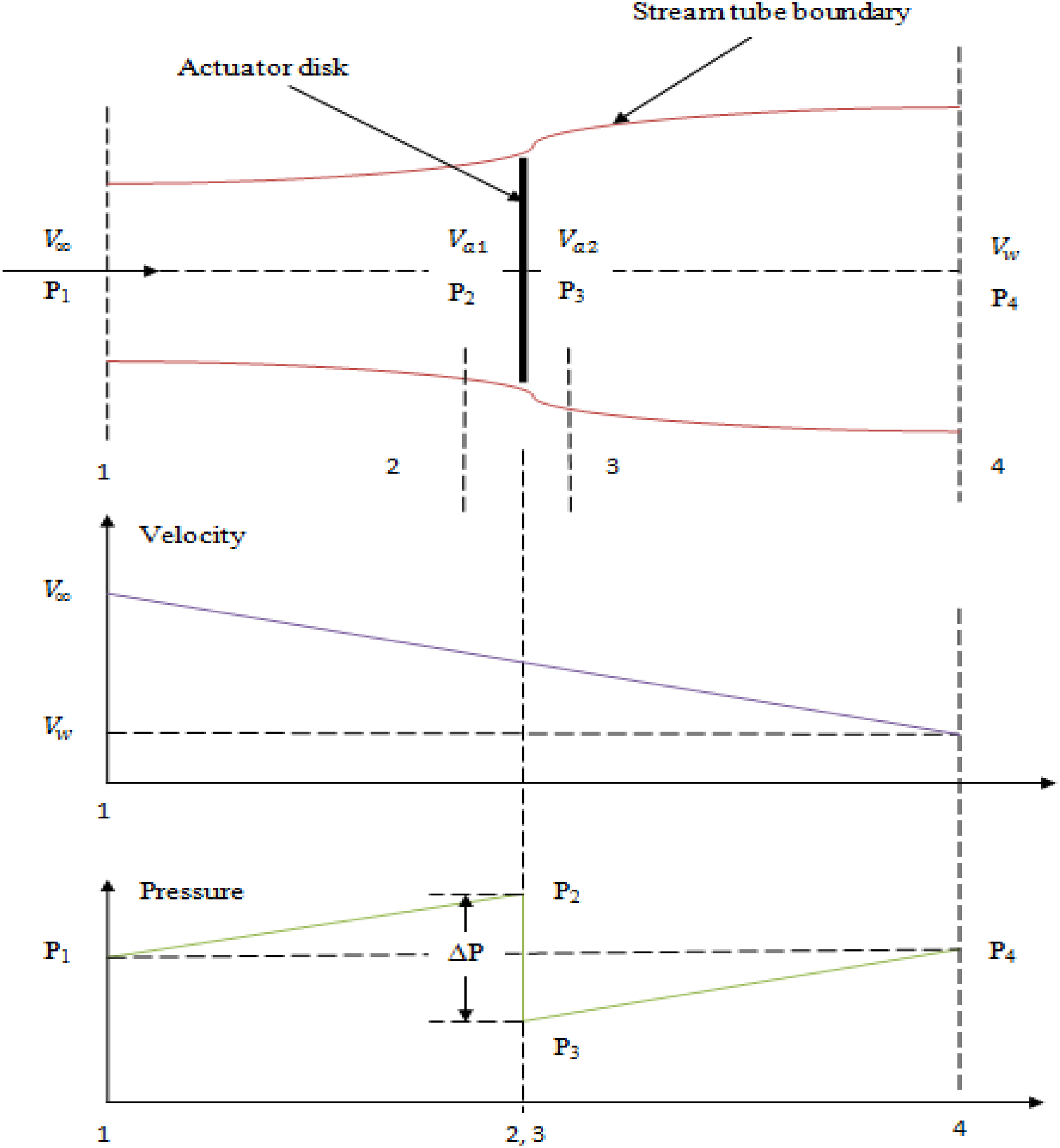
Actuator disc, pressure and velocity variations (Abdul and Mustafa, 2016; Kalakanda and Nallapaneni, 2016).
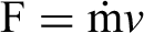
Force, F as,
Thrust, T as,


By applying Bernoulli's principle at two sections as upstream and downstream we have,


As,

In addition, thrust is,

By substituting equation (4) into equation (5) we have,

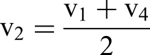
By equating equations (1) and (6), velocity at the disc plane can be calculated as,
The partial reduce in velocity is recognized as axial initiation factor, “a” furthermore it is articulated as,
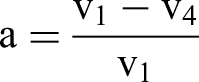
Therefore,


Putting the values of

The turbine power given as,
Also,

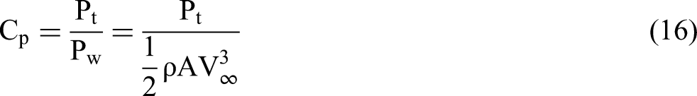
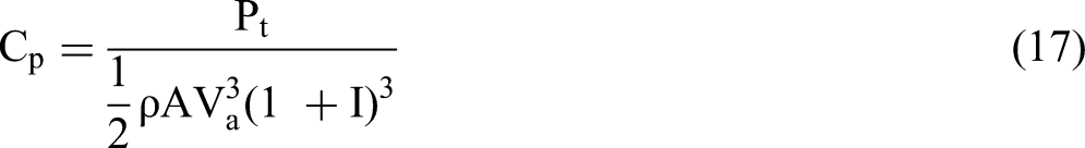
Power coefficient,
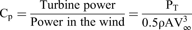
Using equation (10) and

Differentiating equation 11 one can get maximum power coefficient as,

where,
For the ideal turbine, maximum power coefficient is equal to 0.59 and it's known as Betz Limit.
Analytical models
In the present study, two models, namely, the SST and DMST are employed in the present article for estimation the concert of the turbine. These models have certain advantages, like quick, reliable, and accurate results, as mentioned in (Sakiru Folarin Bello et al., 2024; Tao Hai et al., 2024). Templin presented the SST model in 1974. It is simple, in addition to a dependable model, to compute an assortment of smooth/aerodynamic distinctiveness of VAWTs. The energy principle with turbine blade element hypothesis is presented in SST. Concerned same model is explained in the form of a flowchart, and it is represented in Figure 2. There in the flow, velocity of wind decreases and it is calculated by factor known as induction factor. This induction factor is calculated as, 1. Calculation of Thrust
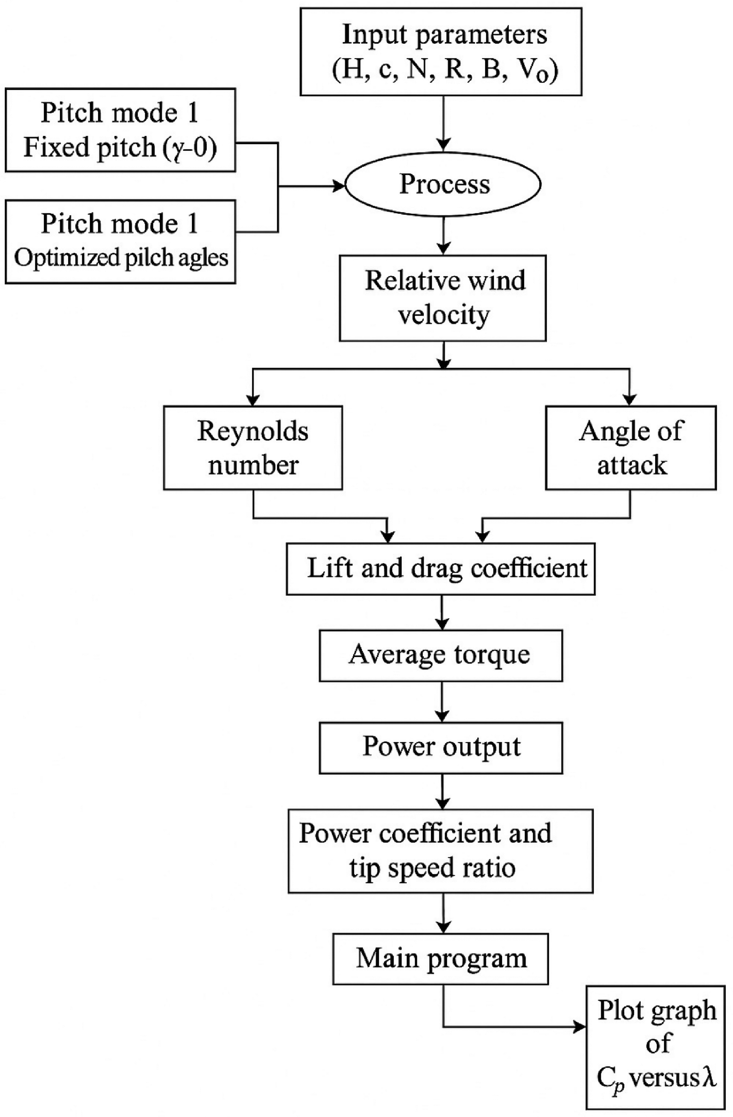
Flowchart of SST model. SST: single stream tube.
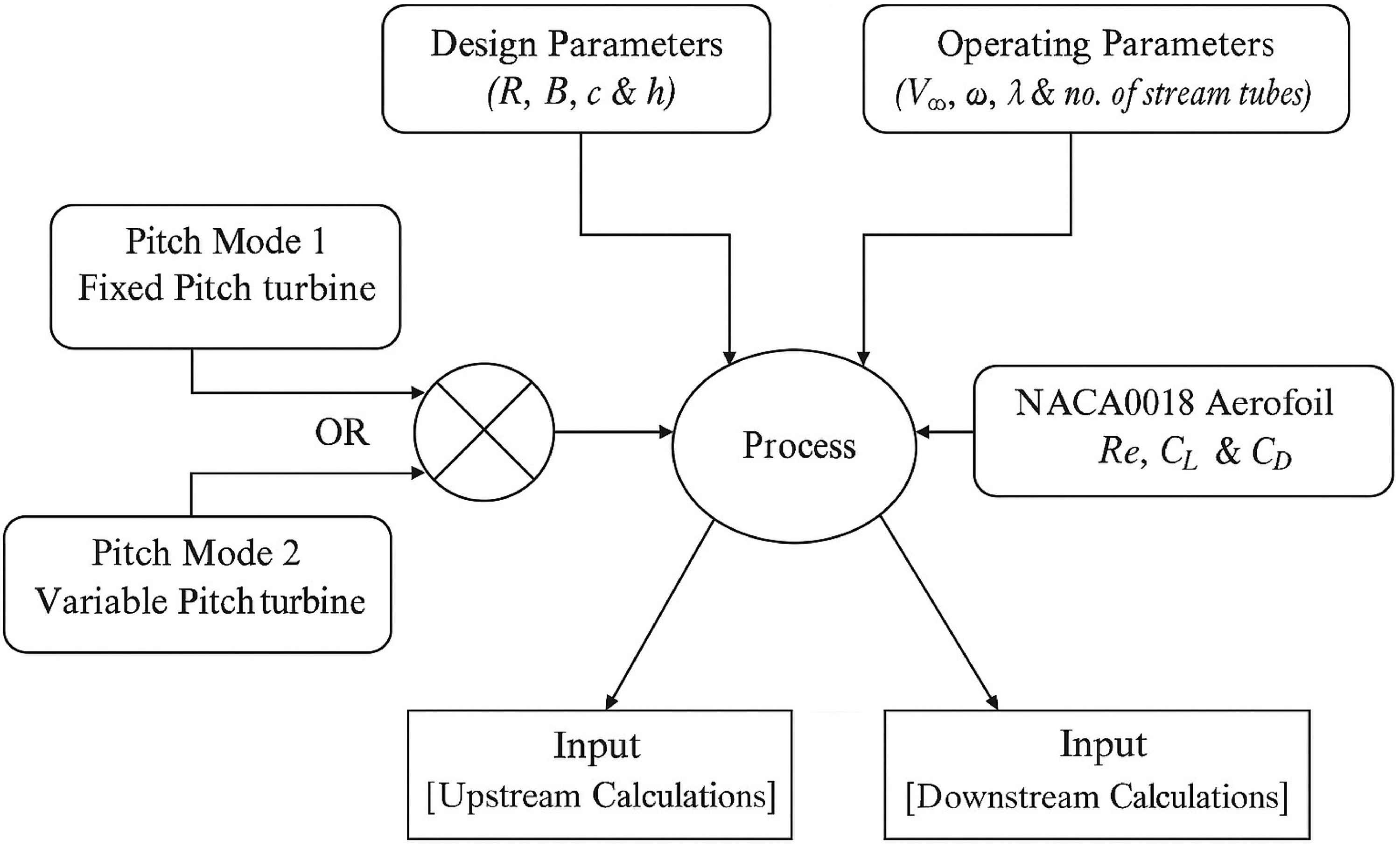
(a) Flowchart of initial calculations with DMST model; (b) upstream calculations; and (c) Downstream calculations. DMST: double multiple stream tube models.
The drive force known as thrust on turbine blade contradictory to wind flow force is presented with equation as,

The total drive force/thrust is calculated by, 2. Calculation of Power Coefficient

Energy output of turbine is expressed in terms of

The assumptions of the present models are as,
The flow is considered steady, inviscid, incompressible, and irrotational. The no viscous flow is considered. The effect of viscosity of fluid is neglected. The density of air is assumed constant, hence flow is incompressible. The fluid element does not rotate and it moves along the streamline, hence flow is irrotational. Dynamic stall effect and vortex effect is neglected as no separation of wind flow from blades.
DMST model developed with Benedict et al. (2013) is used to forecast the behavior of turbines in terms of efficiency. This model uses multiple parallel Stream tubes divided into two parts, upstream range is given in terms of −π/2 < θ < π/2 and downstream range is π/2 < θ < 3π/2. The upstream and downstream forces are calculated separately using different induction factors. The details of the DMST model are represented in the form of a flow chart. The process of the DMST model is divided into three parts; namely, initial calculations with input parameters, upstream calculations, and downstream calculations are represented in a flow chart as represented by Figure 3(a) to (c), respectively.
The upstream and downstream power coefficients are added together to get the total or gross power output of the turbine. It is given as (Kavade and Ghanegaonkar, 2017; Kavade and Ghanegaonkar, 2019):
Speed of turbine (λ range).
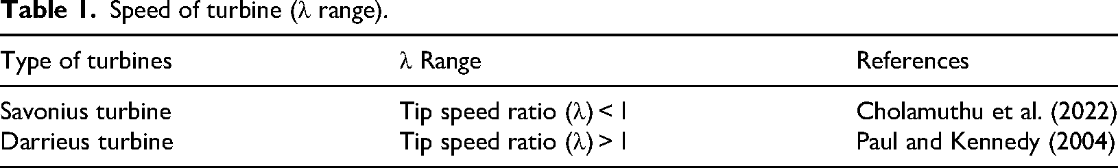
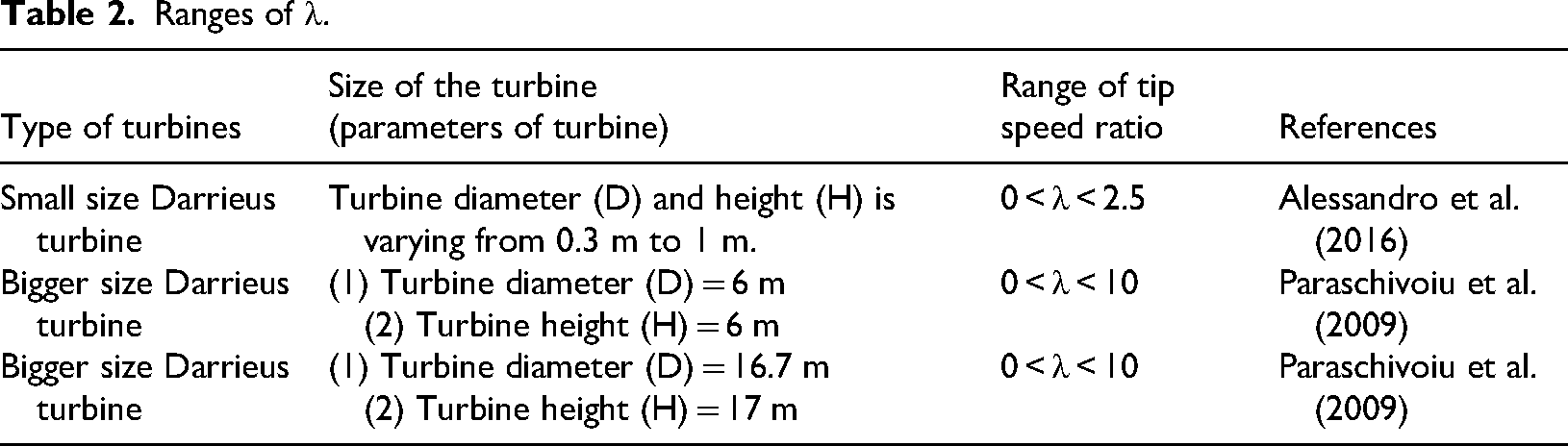
The primary purpose of this research is to propose and build up a small turbine for the generation of electrical power up to 0.1 kW. According to the literature review, a range of λ between zero and three (0 < λ < 3) is selected for the present research. The ranges of λ referred to in the various references are given in Tables 2 to 4 show angle α [°] for fixed and variable pitch turbine. Table 5 shows turbine details used for the current work.
Ranges of λ.
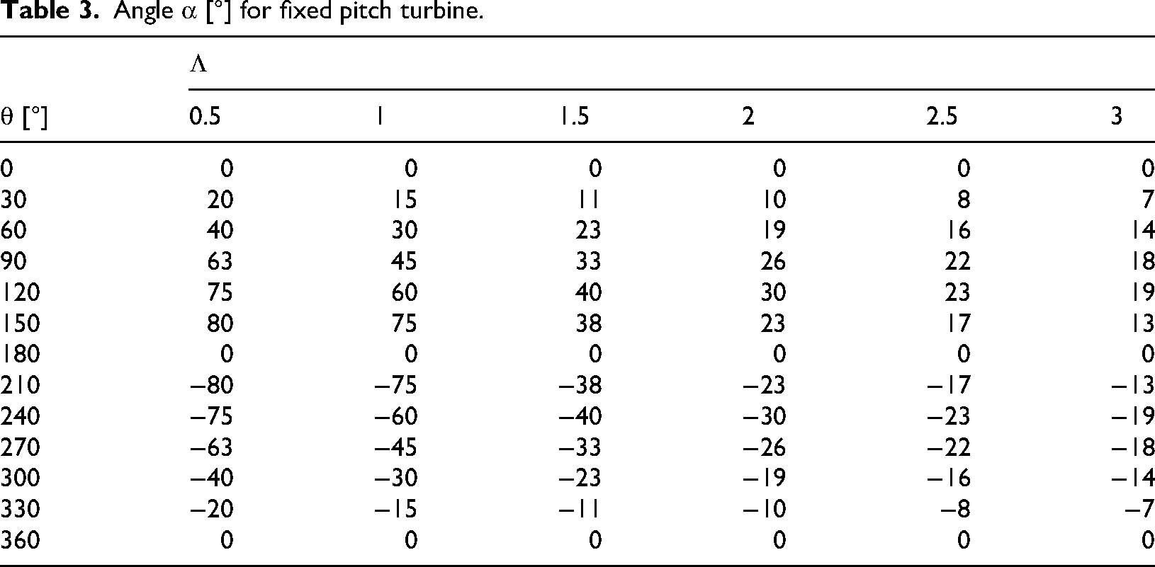
Angle α [°] for fixed pitch turbine.
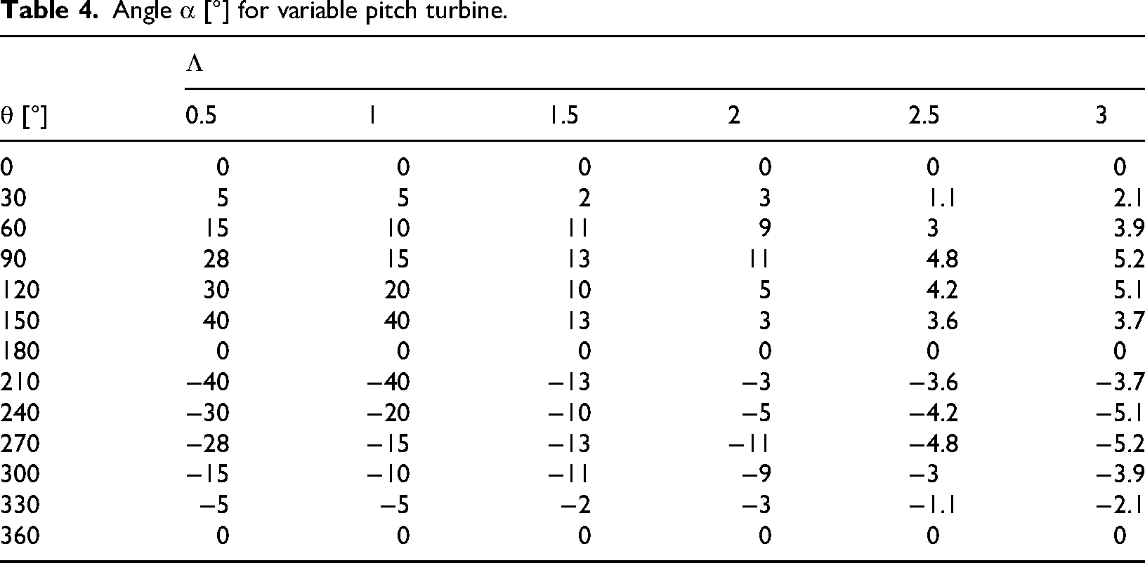
Angle α [°] for variable pitch turbine.
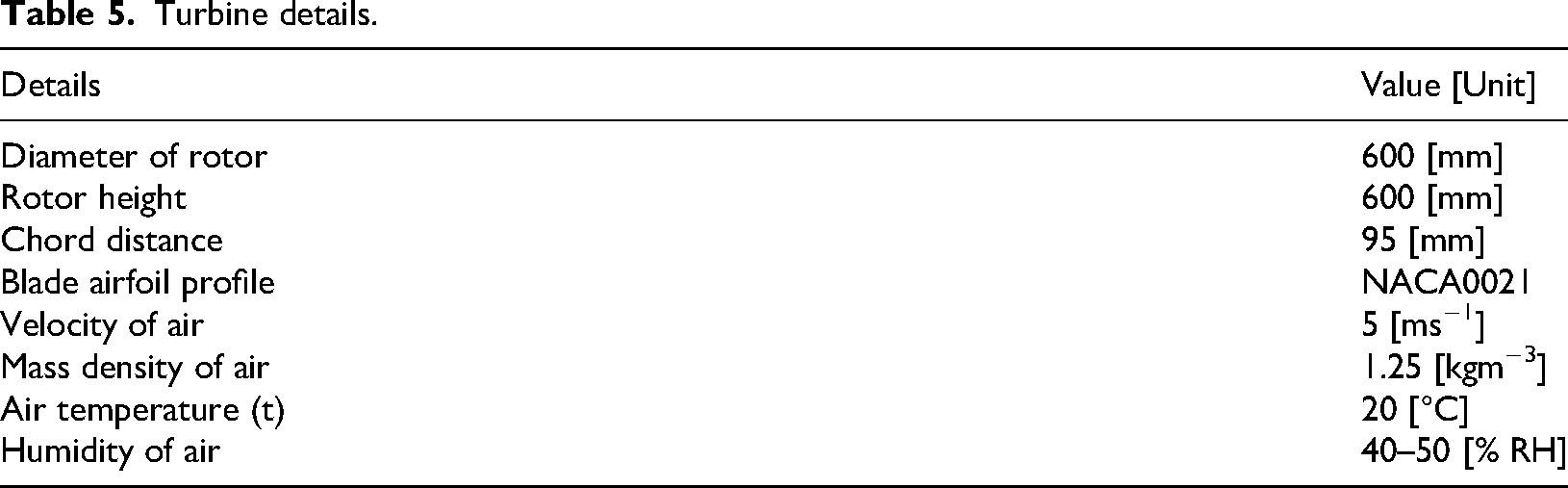
Turbine details.
The current study of variable blade pitching is carried out by using single and double-stream tube models as described in the above sections. The simulation code for current study is validated as presented in Figure 4 (Ivanov et al., 2017). The validation of the simulation code reports variations up to 2% to 5%, as shown in Figure 4. The results for tangential forces for fixed/constant and changing/variable pitch turbines are calculated by using the referred validated simulation code. Figure 5 shows variation of α for a fixed pitch turbine. The results obtained for tangential forces are presented in Tables 6 to 8. It is also used to calculate the energy output in terms of power coefficient for different variable pitch curves, as results presented in Figures 6 and 7.
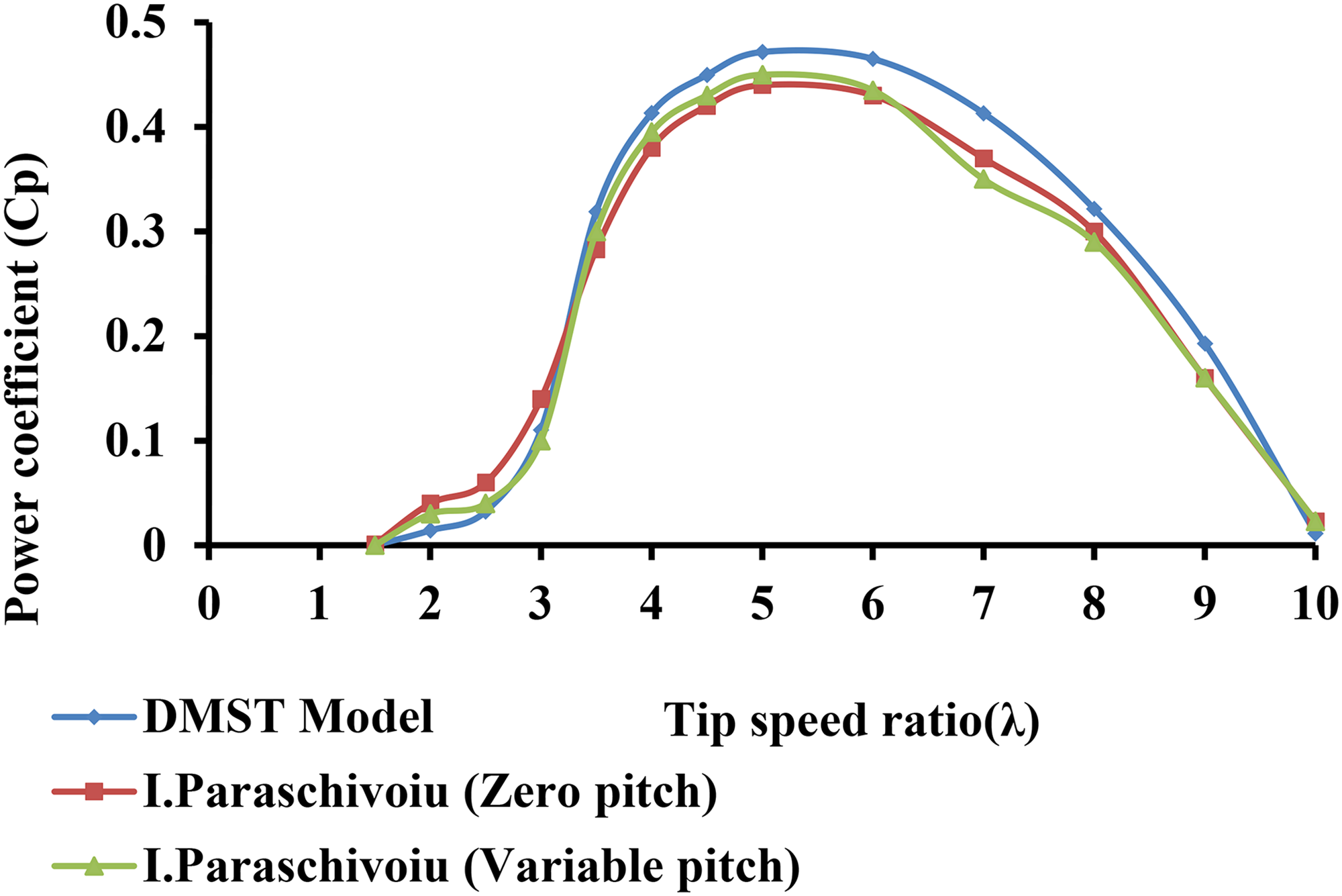
Validations of results (Ivanov et al., 2017).
Variation of α for a fixed pitch turbine.
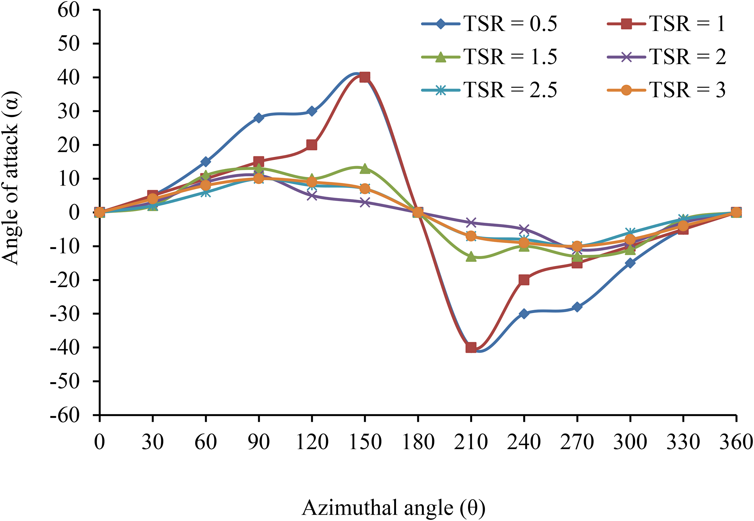
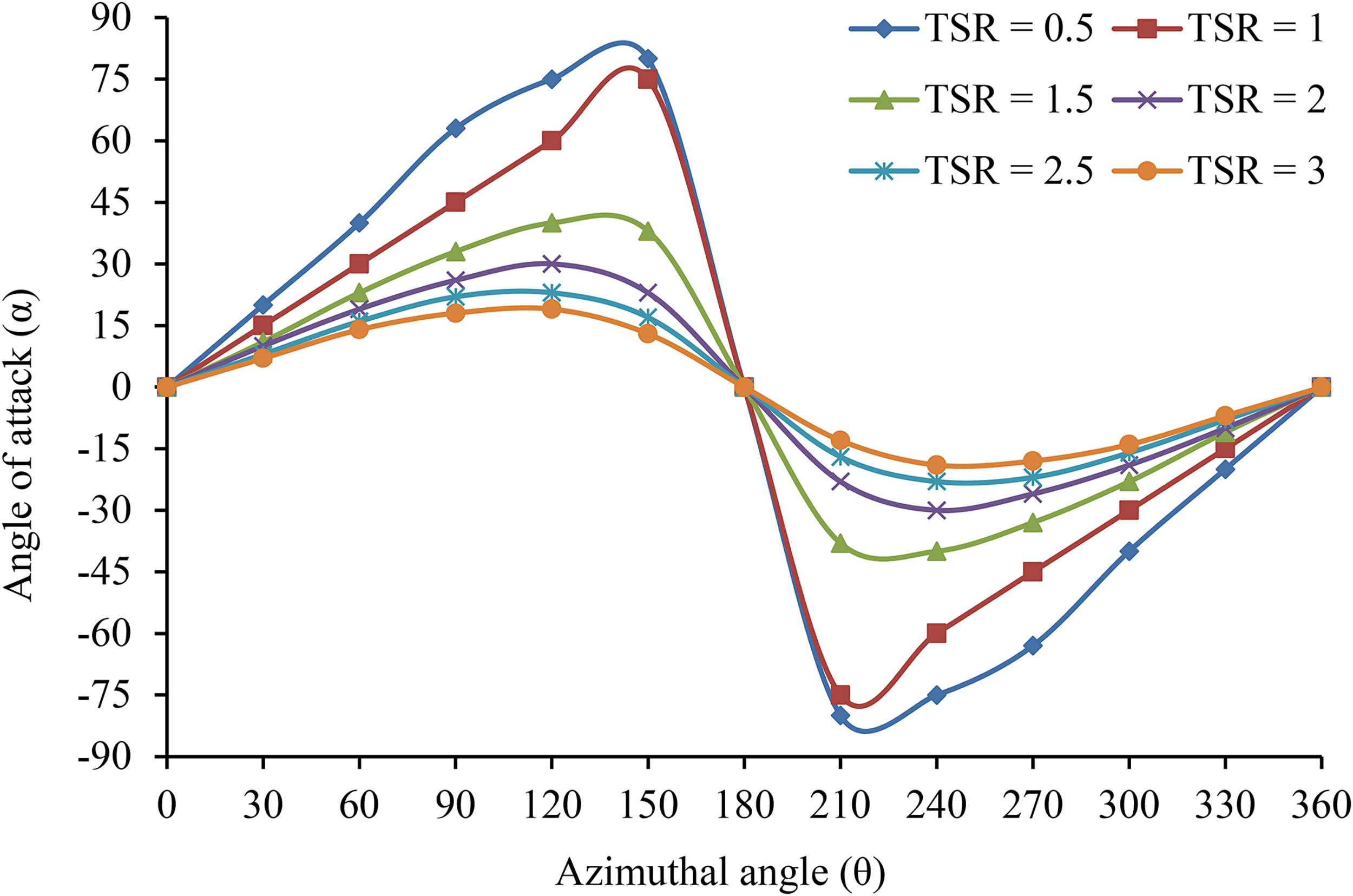
Variation of α for a variable pitch turbine.
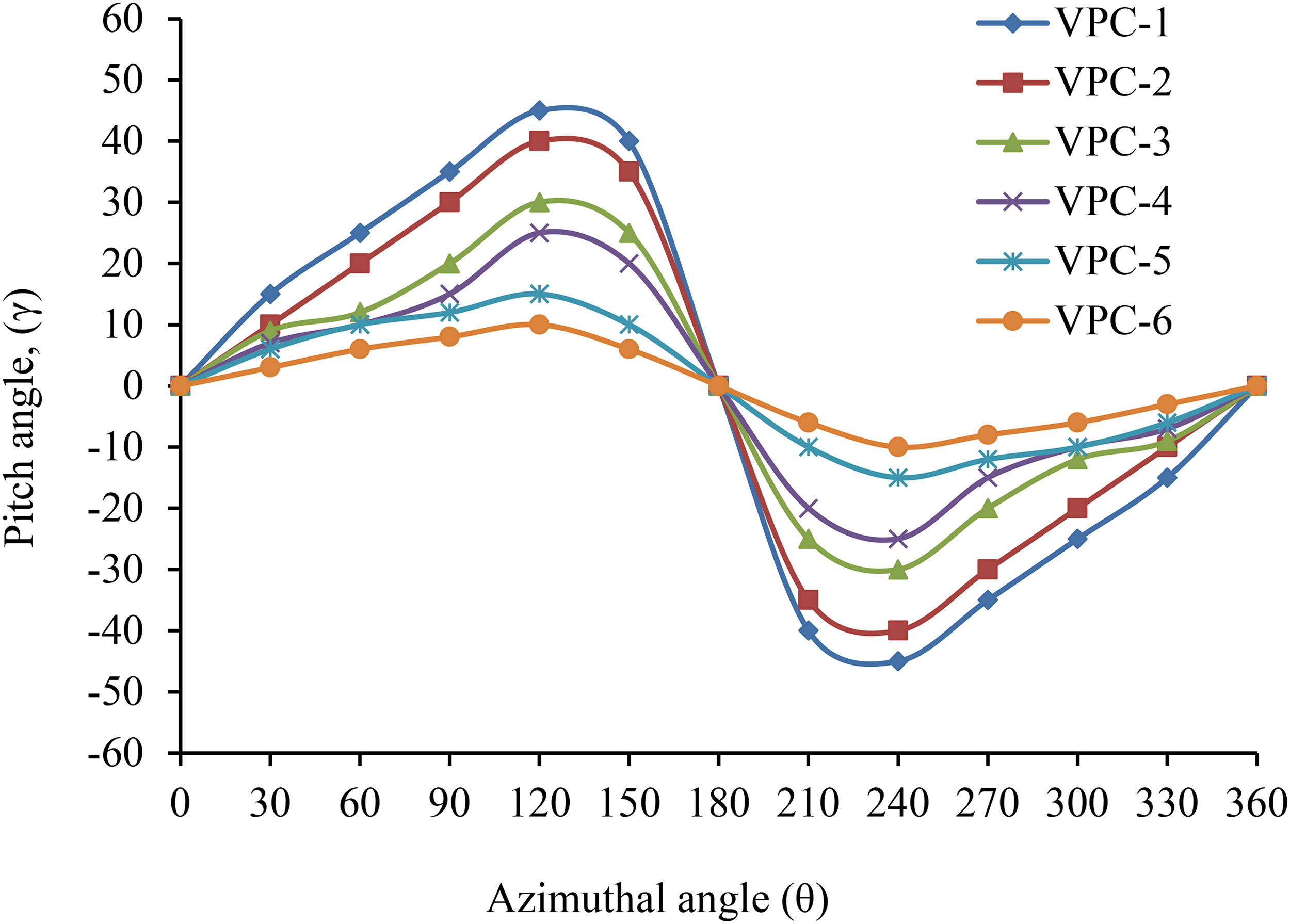
Variable pitch curves for λ (Table 4).
Tangential force, Ft (N): fixed pitch turbine (TSRs 0.5 <λ < 3.0).

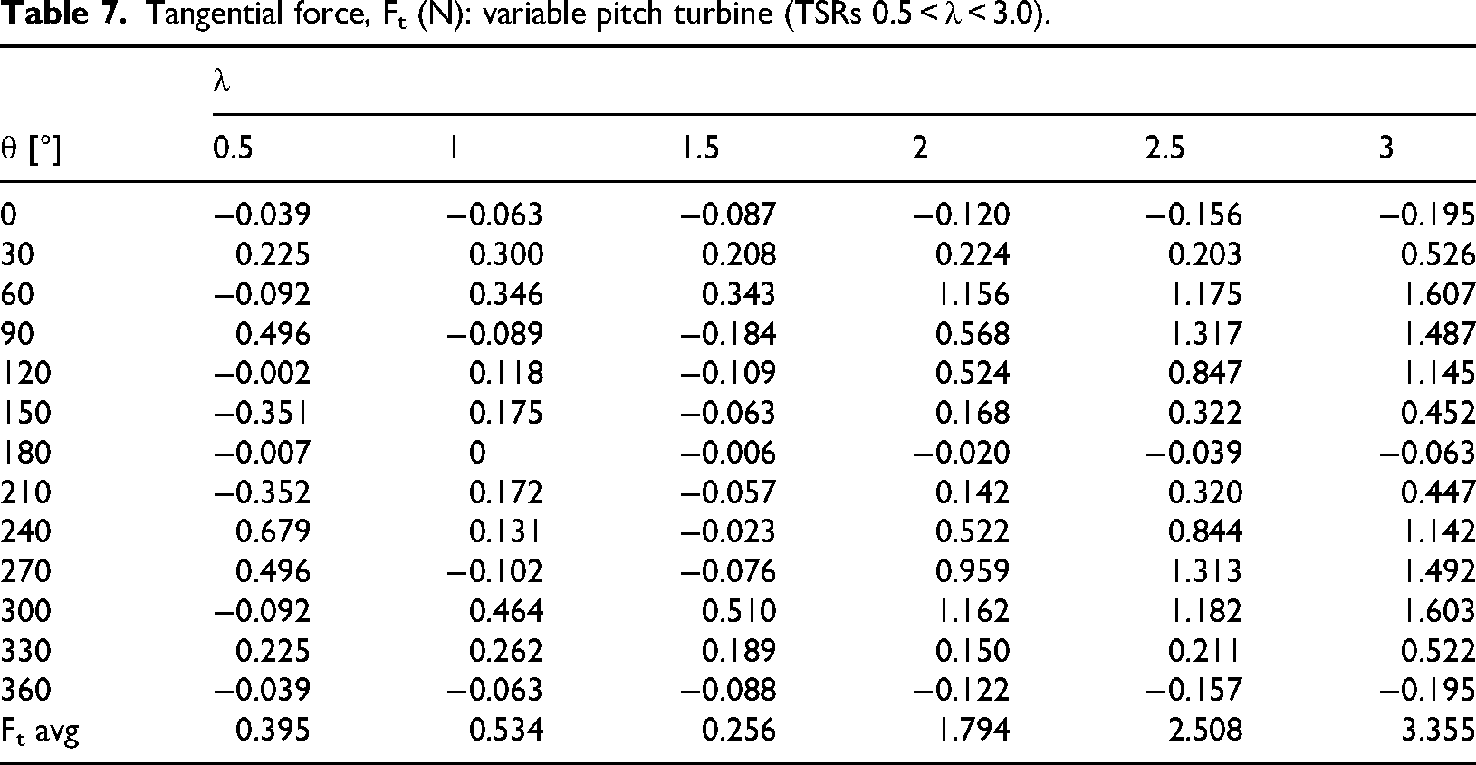
Tangential force, Ft (N): variable pitch turbine (TSRs 0.5 < λ < 3.0).
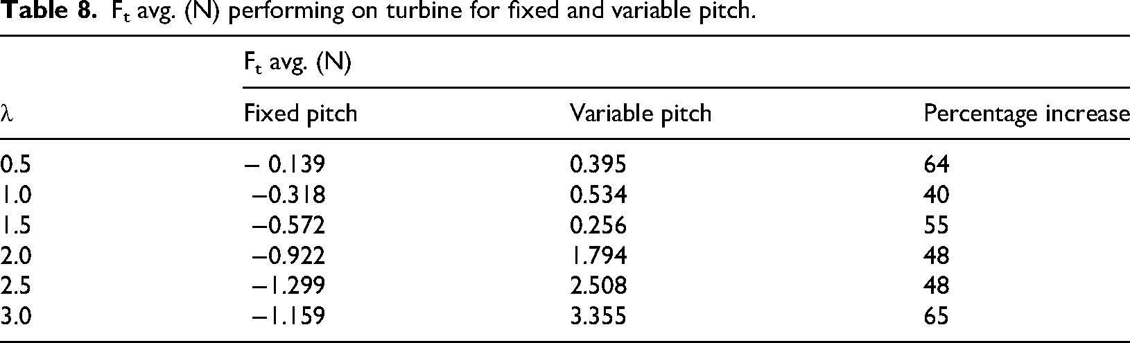
Ft avg. (N) performing on turbine for fixed and variable pitch.
Results and discussions
Tangential forces at fixed and variable pitch turbine
The best pitch schedule (BPS) curves for different TSRs are set for the maximum tangential force. In this analysis, blade profile, chord length, air mass density, air velocity, diameter, and height of 600 mm, respectively, are used for tangential forces calculation. Lift type Darrieus turbine operates because of resulting tangential force/trust in the pathway of movement, which is caused by lift and drag forces generated by crosswise airfoil blades. The tangential forces are obtained for fixed and variable pitch at twelve azimuthal angles at different TSRs. The calculations are carried out using the SST model, as explained by the flow chart (Figure 2). The databook given (Tao Hai et al., 2024; Willy Tjiu et al., 2015) is used for the above calculations. The outcome of turbine is accessible in tabular form in Tables 6 and 7. The hostile tangential forces at various locations of turbine blade are obtained for fixed pitch blades, as shown in Table 6. However, the tangential forces are positive at various azimuthal positions of the blade for a variable pitch with the best blade pitching positions, as shown in Table 7. The average tangential force in a rotation of both turbines is calculated and compared with each other, as shown in Table 8. The angle of attack is critically decided to achieve maximum tangential force by setting the best Variable Pitch Curves (VPC) for different TSRs. Therefore, VPC for each blade of the turbine at various TSRs give positive tangential force and torque to the revolved turbine and increase the performance of the turbine. Standard atmosphere conditions are considered for air characteristics. Air density = 1.25 kg/m3, temperature = 20°C, and humidity = 40% to 50% RH.
In this research article, angle of attack which is the angle made by the relative velocity (
The angle of attack (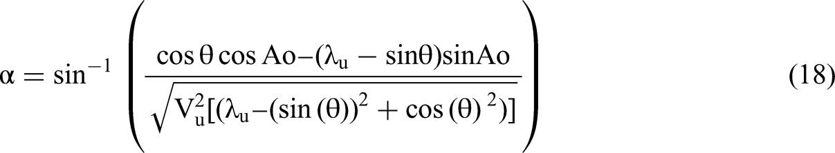
Analysis of variable pitch curves
The six VPC, VPC-1 to VPC-6, as shown in Figure 7, were designed and used for the present analysis. According to the aerodynamic study, it is understood that the initial starting and power output of the turbine/rotor primarily depend upon the drag generated on the tip of a blade of the turbine. Therefore, the pitching of the blade is to be done carefully with the speed of the turbine. At low speed, drag is a prominent force that is required for the initial start of the turbine, and when it takes speed, the drag force is required to be silent, and lift is to be increased with the speed of the turbine. Hence, one specific variable pitch schedule is not suitable for the turbine's wide range of TSRs.
The six pitch curves are designed for different speed of the turbine. These curves are based on best position of pitch angle at different azimuthal blade angles. These six pitch curves are different by the angels of attack (α) only. For pitch curve 1 maximum angels of attack is 40° while for pitch curve 6 maximum angle of attack is 3.7°. The details angle of attack for each curves are mentioned in Table 4.
The present analysis is carried out with six TSRs with a span of 0.5 in the range of 0 < λ < 3. Therefore, to cover the wide range of TSRs, variable pitch curves as VPC-1 to VPC-6 for different TSRs ranges from 0.5 to 3 with regular interval of 0.5 TSR. Another important parameter for analysis is turbine solidity. It depends on blade size and quantity and how they are placed in the path of wind. If blades are closer to each other by large size and number, then drag force acts more on the turbine. Therefore, it is concluded that solidity is mainly dependent on the physical or geometrical parameters of current model of rotor or turbine. Its concert is analyzed considering solidity. According to a literature survey, very high and shallow solidity limits are obtained as σ= 1 and σ = 0.1, respectively. In this analysis, turbine solidity is used in a limit of high solidity = 0.8359 and low solidity = 0.1591.
The concert of current turbine model with pitch curve 1 to pitch curve 6 is evaluated for differences TSRs. The specifications of current turbine or rotor model as given in Table 5 used for present analysis. The analytical results are represented in Figure 8.
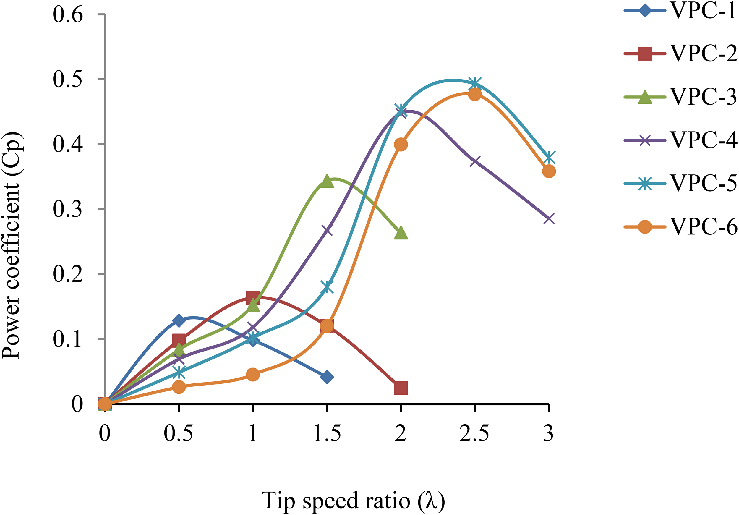
Cp versus λ for optimized variable pitch curves.
Azimuth angle is the position of blade with respect to wind direction. Power is calculated with rotation of turbine. It depends on tangential force at the tip of turbine blades. For fixed pitch turbine the maximum tangential force of 0.847 N and 0.855 N is obtained at azimuthal angle of 30° and 330° as mentioned in Table 6. For variable pitch turbine maximum tangential force of 1.607 N and 1.603 N is reported at 60° and 300° as mentioned in Table 7.
The diagnostic study is obtained with designed VPCs (VPC-1 to VPC-6). According to result, the maximum Cp was obtained by the optimized pitch curves in the specified range of λ. The maximum power coefficient obtained by these results as Cp = 0.09 at λ = 0.5 from VPC-1, Cp = 0.14 at λ = 1 from VPC-2, Cp = 0.20 at λ = 1.5 from VPC-3, Cp = 0.45 at λ = 2 from VPC-4, Cp = 0.53 at λ = 2.5 from VPC-5, and Cp = 0.37 at λ = 3 from VPC-6. The maximum energy output in terms of power coefficient of 0.53 is at λ = 2.5 from VPC-5, which is superior to the same obtained from all other VPCs. Therefore, the VPC-5 was selected to conduct trials on turbines.
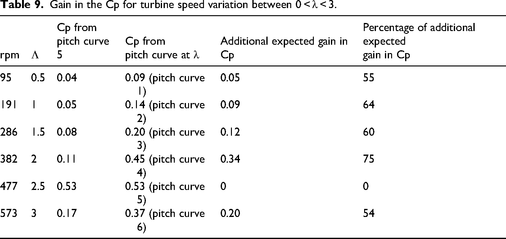
According to analytical results, the specification of the turbine model with VPC-5 for the pitching turbines was decided for the fabrication of a variable pitch turbine. The analysis is carried out for VPC-5 with other pitch curves, as mentioned above, at various TSRs ranging from 0 to 3. The analytical results, as discussed above, are reported in tabular form, as represented in Table 9. The gain of power coefficient associated with this analysis varies from 54% to 75% for various λ, as shown in Table 9. If the pitch VPC-1 is used instead of pitch VPC-5 at λ = 0.5 gain in Cp is 0.05, VPC-2 instead of VPC-5 at λ = 1 gain in Cp is 0.09, VPC-3 instead of VPC-5 at λ = 1.5 gain in Cp is 0.12, VPC-4 instead of VPC-5 at λ = 2 gain in Cp is 0.34, VPC-5 at λ = 2.5 gain in Cp is 0, and VPC-6 instead of VPC-5 at λ = 3 gain in Cp is 0.20. The variation of gain in Cp is presented in Figure 9.
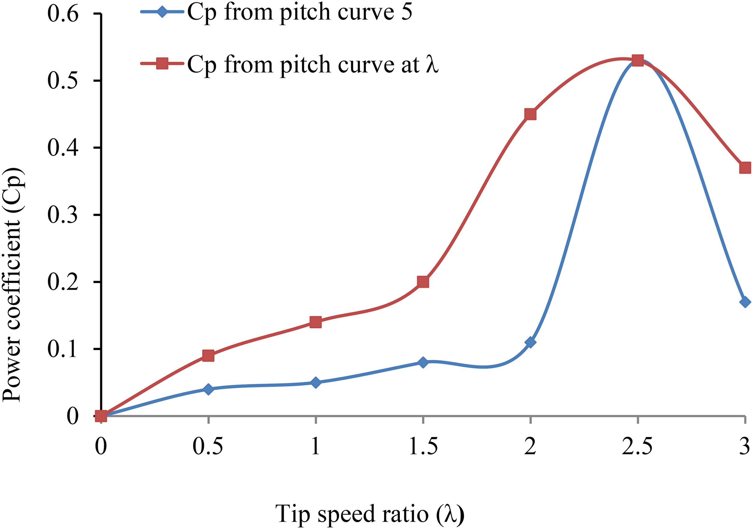
Analysis for Cp of pitch curve 5 at different λ.
Gain in the Cp for turbine speed variation between 0 < λ < 3.
Conclusions
In this research article, results indicate that the variable pitching of the turbine is a more effective solution than fixed/constant pitch, and the Cp of turbine is reported as 0.53 at λ = 2.5 from VPC-5. Further, analytical results are obtained between 0.01 and 0.45 in the span of TSRs of 0 < λ < 3. According to the Betz limit, performance cannot be more than 0.59. Referring to the above results, the concert of changeable pitch turbine model is quite close to the Betz limit. Even the overall power coefficient of the turbine can be improved if specified VPCs obtain pitching in each range of λ. The conclusion can be summarized as follows:
According to analysis for VPC-5 with other VPCs used in this research, a gain of power coefficient of about 54% to 75% is observed at TSRs of 0 < λ < 3 other than λ closer to 2.5. Therefore, it is suggested for more efforts in to development of pitching mechanisms, which gives optimized pitch angles with azimuthal location of turbine blades at different speeds. Different mechanisms, like the four-bar link mechanism, cam and follower mechanism, and servomotor mechanism, are suitable for making changeable pitch turbine. The mechanical mechanism like cam and follower pitching mechanism consists of various sliding components that produce friction and, hence, generate resistive torque, which lowers the turbine's performance at various TSRs. This frictional loss depends on the size of the turbine. Therefore, the frictional losses associated with these types of mechanisms and their effect should be studied for various sizes of the turbines. The frictional loss depends on the surface finish of different parts of pitching mechanisms. Therefore, the surface finish and material parts of this mechanism should be improved. As discussed in this article, one variable pitch curve schedule is not suitable for obtaining maximum power over a wide range of TSRs. At the low speed of the turbine or low TSRs, VPC-1, or VPC-2 is suitable, but they cannot perform well at high TSRs, as reported in Figure 7. A servomotor mechanism, as it is microcontrolled, is recommended to get the turbine pitching in a wide range of TSRs. Variable pitch systems present a number of difficulties for small-scale wind turbines, even if they can improve performance by adjusting the angle of attack. Compared to fixed-pitch designs, the main problem is the additional mechanical complexity, which can result in more significant starting costs and more frequent maintenance requirements. The cost and weight of the precision parts needed for variable pitch systems may affect the turbine's efficiency-to-cost ratio. The viability of small-scale applications is further complicated by the fact that they frequently run in isolated or dispersed areas with restricted maintenance accessibility. Because of these characteristics, it is crucial to balance economic and practical issues with performance advances in such systems.
Footnotes
Acknowledgement
Authors are thankful to Guangxi Science and Technology Program under Grant No: AA24010001. This research was financially supported by First-class Discipline Construction Project of Hechi University, Guangxi Colleges and Universities Key Laboratory of AI and Information Processing (Hechi University), Education Department of Guangxi Zhuang Autonomous Region.
Funding
The authors disclosed receipt of the following financial support for the research, authorship, and/or publication of this article: This research was funded by the Guangxi Science and Technology Program under Grant No: AA24010001. This research was funded by the Guangxi Science and Technology Program under Grant No: AA24010001. This research was financially supported by First-class Discipline Construction Project of Hechi University, Guangxi Colleges and Universities Key Laboratory of AI and Information Processing (Hechi University), Education Department of Guangxi Zhuang Autonomous Region. Authors thankful to Ongoing Research Funding program (ORF-2025-999), King Saud University, Riyadh, Saudi Arabia.
Declaration of conflicting interests
The authors declared no potential conflicts of interest with respect to the research, authorship, and/or publication of this article.