
Abstract
The thermal performance of solar air heaters can be significantly enhanced by modifying their design to overcome the limitations posed by the thermo-physical properties of air. In this experimental study, the impact of perforated obstacles with varying hole diameters (2, 3, 4, 5, and 6 cm) placed on the absorber plate of a solar air heater was investigated. The primary objective of this study is to experimentally assess the influence of different perforated obstacle configurations on thermal efficiency, effective efficiency, and pressure drop in a solar air heater, thereby identifying the most effective design for optimizing overall system performance. Tests were conducted in Fez city under two mass flow rates (0.025 and 0.039 kg/s). The results indicated a substantial improvement in thermal efficiency and heat exchange due to the turbulence created by the obstacles. At the higher flow rate (0.039 kg/s), the collector under Type V obstacles (hole diameter: 2 cm) achieved a maximum thermal efficiency of 85%, whereas at the lower flow rate (0.025 kg/s), the same obstacle type yielded a thermal efficiency of 69.5%. These values represent increases of 36% and 33%, respectively, compared to a simple collector. Effective efficiency, which considers the pressure drop in the channel, was also analyzed. At 0.039 kg/s, Type V obstacles exhibited an effective efficiency of 36%, while at 0.025 kg/s, the effective efficiency was 33.85%. Despite the increased pressure drop with smaller hole sizes, the enhanced heat transfer and temperature difference ensured an overall improvement in system performance. This study demonstrates that perforated obstacles are a viable method to optimize heat transfer and airflow dynamics in solar air heaters.
Introduction
The public's attention has increasingly shifted toward the pressing issue of climate change, driven by the alarming rise in air pollution and global warming stemming from the excessive use of fossil fuels. The interconnected nature of these environmental challenges has sparked a growing awareness of the urgent need for collective action to mitigate their destructive effects. As scientific evidence continues to mount, public concern and advocacy have surged, prompting calls for sustainable solutions and policy interventions. Renewable energy, particularly solar power, has witnessed a surge in popularity in recent years as consumers increasingly prioritize sustainability and environmental consciousness. This shift in consumer preferences toward solar energy is driven by a combination of factors, including advancements in technology, economic benefits, and growing awareness of the need to combat climate change (http://homerenergy.com). Solar water heaters and solar air heaters are commonly used for heating homes and other low-temperature applications. Advances made in the past decade have simplified the construction of air heaters and reduced their cost (Ebazadeh et al., 2024; Rajhi et al., 2024). Air heaters are usually used to provide hot air for drying agricultural products and pre-heating fresh air in industries, air conditioning, domestic hot water, dryers, and other industrial and thermal processes (Didi et al., 2024; Rajhi et al., 2024). Flat plate air heaters are superior to water heaters in terms of structure simplicity, required parts, price, complexity, and maintenance. Also, in practice, they do not face problems such as clogging, leakage, corrosion, and freezing of water. Despite all these advantages, some disadvantages limit their thermal performance. The low density and heat capacity of air have unfavorable physical-thermal properties (Albaker et al., 2023; Su et al., 2023). This leads to a low heat transfer rate between the absorbent plate and the fluid flow in solar air heaters, ultimately reducing their thermal efficiency (Chen et al., 2023; Lin et al., 2023).
Researchers have proposed various changes to the structure of air heaters in order to improve their thermal performance. One important change is adding artificial roughness, baffles, or obstacles in the air passage channel. This disrupts the flow, increasing the heat transfer coefficient between the air and the absorbent plate. A higher heat transfer coefficient means more convective heat transfer, resulting in improved thermal efficiency. However, adding obstacles also increases the pressure drop in the channel, requiring more power from the blower and reducing collector efficiency. Researchers are seeking the best combination to maximize heat transfer rate while minimizing pressure drop. The low thermal conductivity and heat capacity of air pose challenges for effective heat transfer in solar air heaters, with forced convection being the dominant heat transfer mode. Researchers have explored methods to enhance convection by modifying air passage channels with artificial roughness and obstacles. Such innovations improve the convective heat transfer coefficient, effectively increasing the Nusselt number. This study investigates how perforated obstacles strategically placed on the absorber plate improve convective heat transfer through enhanced turbulence, resulting in significant thermal efficiency gains.
Ahmed-Zaid et al. (1999), Abene et al. (2004), and Sahu et al. (2021, 2022) utilized various obstacles within a solar collector to raise the air outlet temperature and prolong the drying time for agricultural products (yellow onions and grapes). Reduced compared to when using an unobstructed collector. These obstacles were inverted arch, folded arch, bent pipe, bent arch, and delta. Handoyo et al. (2016) studied a different type of triangular obstacles by using pleated collectors. They conducted experiments to measure the heat transfer and pressure drop at various distances. It was found that by reducing the “distance to height” ratio of the obstacles to 0.5, the Nusselt number increases by about 3.5 times and the friction coefficient increases by about 20 times compared to the case where obstacles are used inside the collector. They also took help from computational fluid dynamics to find the optimal distance at which the highest Nusselt number is obtained with the lowest friction coefficient. Kulkarni et al. (2015) designed a solar collector with obstacles that are optimized to maximize heat transfer and minimize pressure drop. They focused on geometric parameters like the ratio of obstacle height to air passage channel height. Alam and Kim (2016) studied the thermal and hydraulic performance of a solar collector with semi-elliptical barriers at different attack angles and Reynolds numbers. The experimental data has been presented in another work (Kumar et al., 2017; Nadda et al., 2017). Bensaci et al. (2020) researched the impact of baffle positions inside the collector on thermal and hydraulic performance. They found that correct baffle positioning significantly improves thermohydraulic performance. Luan and Phu (2020) developed relationships for the Nusselt number and friction coefficient in a solar collector with inclined baffles. Sharma et al. (2019) investigated flow barriers with different shapes to suggest better designs for solar collectors. Saravanakumar et al. (2019) studied the effect of adding fins and baffles to a rough collector with curved ribs, showing improvements in effectiveness and energy efficiency. The roughness along with the arc ribs improves the effectiveness and energy efficiency by 28.3% and 27.1%, respectively. They also investigated the exergy performance of this collector (Saravanakumar et al., 2020). They also optimized the collector parameters using a genetic algorithm, achieving a maximum efficiency of 5.2% in optimized conditions.
Kumar and Layek conducted experiments on a solar air heater with fins as rough elements on the absorber plate (2021). They compared the performance of the collector in terms of energy, effectiveness, and energy efficiency. Through numerical optimization, they found that the thermal efficiency was 2.12 times, the effectiveness was 1.99 times, and exergy was 2.03 times higher compared to a collector with a simple absorber plate. Saravanan et al. (2021) studied a collector with C-shaped fins in porous and non-porous states. They tested the system's thermohydraulic performance in the Reynolds range of 3000 to 27,000, evaluating parameters like relative pitch, relative height, and relative porosity ratio. They also provided relationships for the Nusselt number and the friction coefficient based on experimental data. Dong et al. (2021) conducted a numerical study on a solar air heater with wavy plates, investigating the impact of dimple range, angle of attack, and number of arrays. The Reynolds numbers ranged from 12,000 to 24,000. They discovered that the slope of the pits significantly influenced the production of longitudinal swirling flow in the collector channel. Sureandhar et al. (2021) developed a thermal model to analyze how the arrangement of curved rib fins and the length of the absorber plate affect the heat dissipation of a solar air heater. They studied two roughness height ratios and two collector lengths, finding that variable arc fins maximized solar energy utilization and output temperature compared to a simple collector design. Sahu and Prasad (2017) studied a thermo-hydraulic performance analysis of an arc-shaped wire roughened solar air heater. Sahu et al. (2021, 2022, 2023) developed an improvement in the performance of solar air heaters.
After reviewing research that studied the performance of hot air collectors with barriers inside the air passage channel, it was noted that there is limited information on the use of porous barriers. Essentially, if the barriers have holes, the air can pass through them, leading to increased turbulence around the obstacles and near the holes. This also results in a significant improvement in heat exchange. This study explores the use of porous barriers in the air path through experiments, examining how the dimensions of the holes impact heat transfer and pressure drop in the collector at different flow rates. The performance of this setup is then compared to a standard collector. Therefore, the main aim of this research is to systematically investigate how the implementation of perforated vertical obstacles with different hole diameters, positioned on a flat absorber plate, affects the key performance metrics—thermal efficiency, effective efficiency, and pressure drop—of a solar air heater. Through a series of controlled experiments, this study seeks to determine the optimal obstacle design that maximizes heat transfer while maintaining a reasonable pressure drop, thereby contributing practical evidence for improved solar air heater design.
The study systematically investigates the impact of varying hole diameters in perforated obstacles placed on the absorber plate of a solar air heater, under controlled mass flow rates, to quantitatively assess improvements in thermal and effective efficiency as well as pressure drop. Further, it introduces and evaluates multiple obstacle configurations with precisely defined geometrical parameters (hole diameters of 2, 3, 4, 5, and 6 cm), aiming to optimize turbulence generation and convective heat transfer without excessively increasing pressure losses. Moreover, the study applies “effective efficiency”—an advanced performance metric that integrates both thermal output and blower energy consumption—to provide a holistic assessment of collector performance, which is rarely addressed in similar experimental studies, and delivers the first detailed comparative dataset for each obstacle type in a real climate/location (Fez, Morocco). The current work establishes design guidelines and trade-off analysis for practical solar air heater optimization, offering a validated performance framework for future system designers to maximize net heat gain while controlling operational penalties (pressure drop and blower energy). In summary, the objectives and scientific contributions of this study are as follows:
To experimentally assess the influence of hole diameter in strategically placed absorber plate obstacles on the overall performance of a flat-plate solar air heater. To optimize obstacle geometry for maximizing heat transfer while minimizing pressure drop. To employ and demonstrate the utility of ‘effective efficiency’ for comprehensive system assessment. To provide the first detailed performance comparison of several obstacle types under actual climatic conditions. To establish validated, practice-oriented recommendations for solar air heater design and operation.
Materials and methods
Fez is the main city in the Fez-Meknes area and is one of the biggest cities in Morocco. There are about 1.256 million people living there. Fez is near the Atlas Mountains and is surrounded by hills. The old part of the city is right by the Fez River, which flows from west to east. The Fez is located at longitude −5° 00′ and latitude 34° 01′, with solar radiation of 5.3 kWh/m2/day. The solar air collector investigated in this study consists of a flat absorber plate with dimensions of 110 cm in length, 50 cm in width, and 2 mm in thickness, as shown in Figures 2 and 3. The air channel above the absorber plate has a uniform height of 5 cm across the entire length and width of the collector. Six perforated obstacles made from 0.5 mm galvanized iron, each 5 cm high and spaced 20 cm apart along the absorber plate, were attached in all tested configurations. The collector is covered by a 5 mm glass sheet, with side walls made from 2.5-cm-thick compressed wood for insulation, and features an additional 10-cm-high static air channel below the absorber to minimize downward heat loss. A flat plate solar air collector under study is shown in Figure 1.
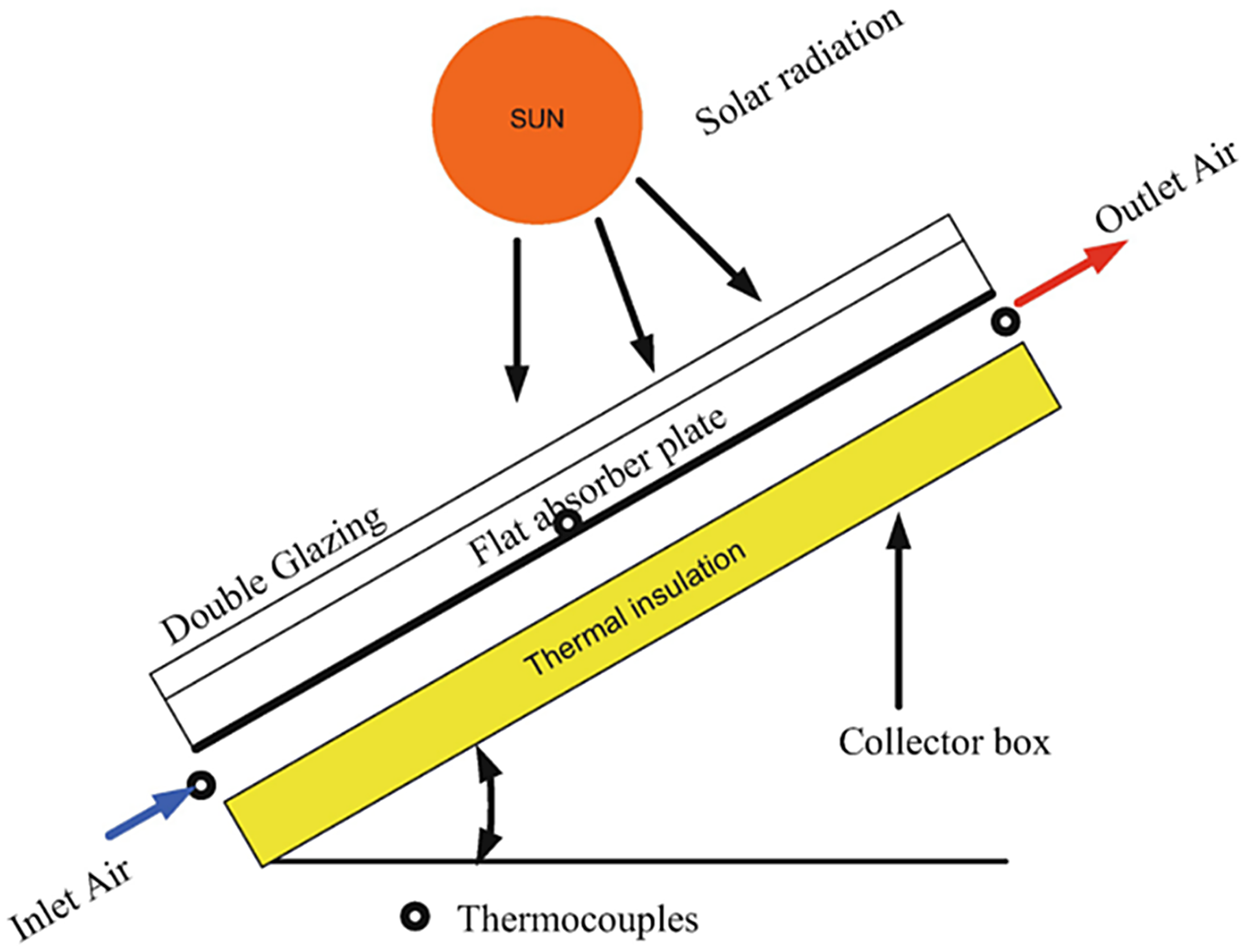
A flat plate solar air collector under study.
Schematic cross-section of the solar air heater used in this experiment, showing (1) glass cover; (2) air channel (5 cm height); (3) absorber plate (2 mm black iron sheet); (4) six perforated obstacles attached horizontally on the absorber plate (0.5 mm thick, 5 cm high, spaced 20 cm apart); (5) static air insulation channel (10 cm height); and (6) wood sidewall insulation. The figure illustrates the experimental configuration of the solar air collector used for performance testing, with heat directed to the outlet for thermal performance measurements. All dimensions shown in this schematic accurately represent the actual geometry of the experimental setup: absorber plate (110 × 50 × 0.2 cm), air channel (5 cm height), perforated obstacles (5 cm high, 0.5-mm-thick GI, spaced 20 cm apart), static air insulation channel (10 cm), and sidewall insulation (2.5 cm).
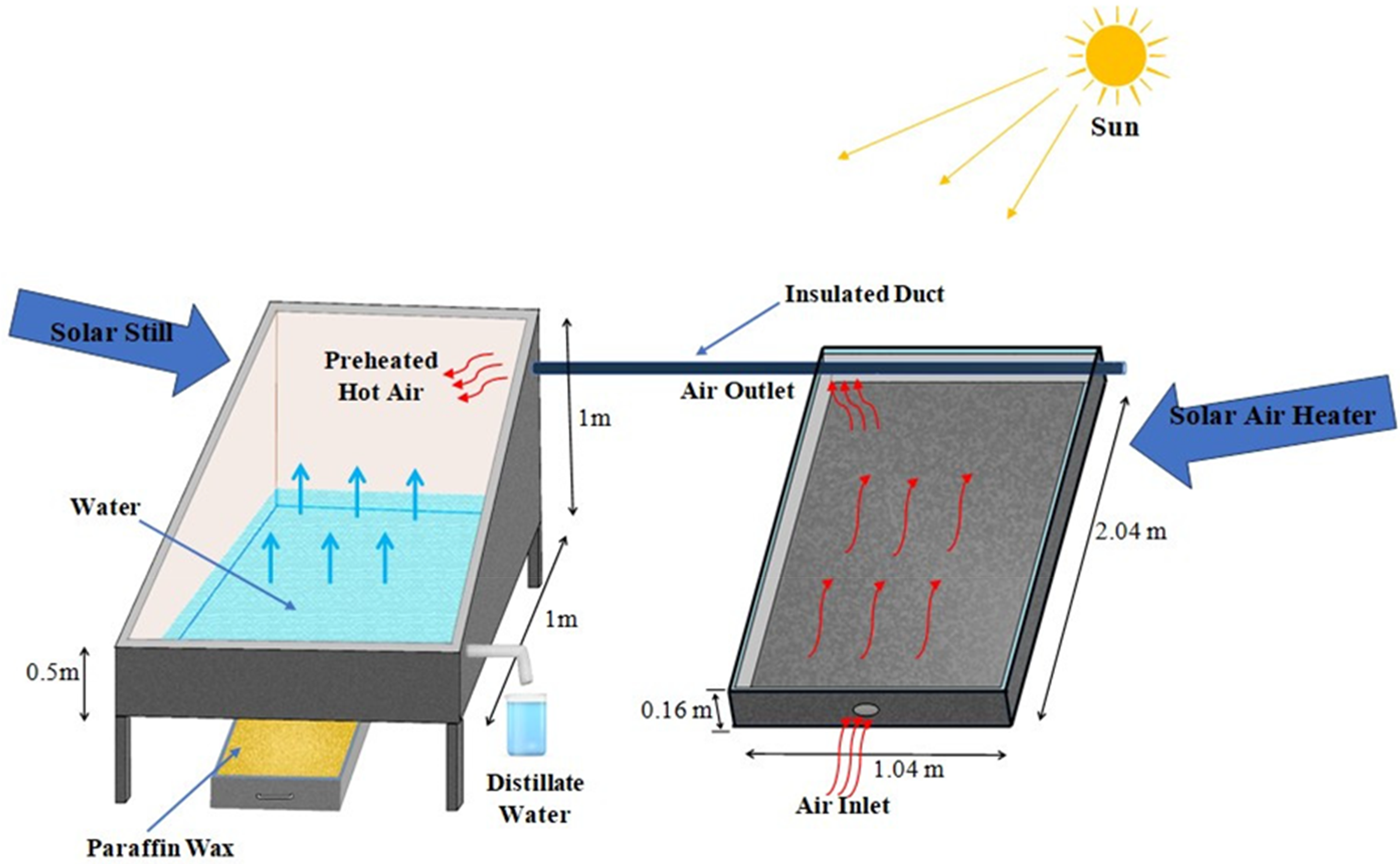
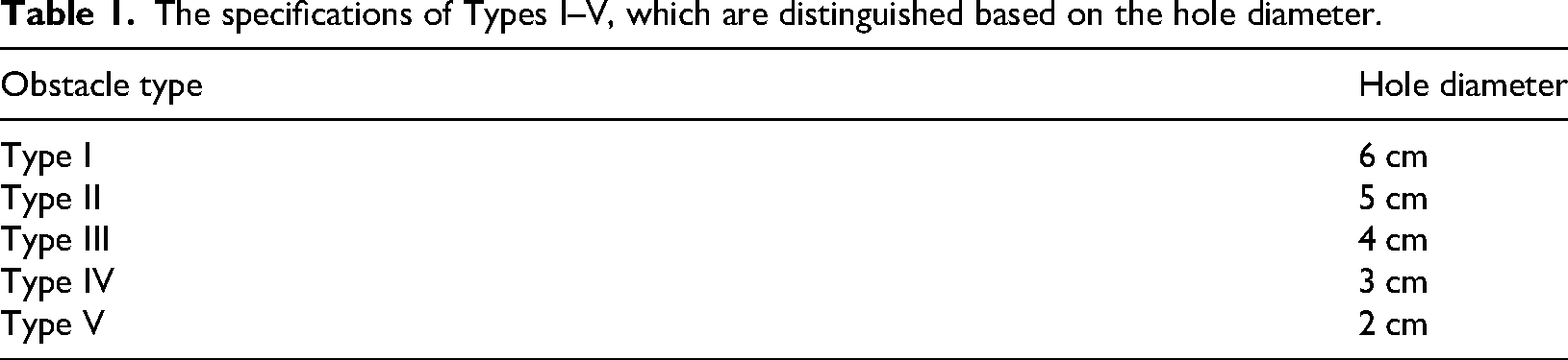
This study tested five different barrier combinations on the absorber plate in the collector. Six obstacles, each 5 cm in height, were attached horizontally on the absorber plate, spaced 20 cm apart. Each obstacle had six holes to allow air passage and disrupt the flow. Type I had holes with a diameter of 6 cm, Type II had holes with a diameter of 5 cm, Type III had holes with a diameter of 4 cm, Type IV had holes with a diameter of 3 cm, and Type V had holes with a diameter of 2 cm. These holes reduced the cross-sectional area of air passage by 9%, 12%, 23%, 31%, 38%, respectively. The study compared the performance of the collector with these barriers to a normal collector (simple absorber plate) to see how the barriers affected performance. The barriers were made of 0.5-mm-thick galvanized iron. An example of Type II of barrier (perforated obstacles with a 5-cm diameter) is shown in Figure 2, colored black like the absorber plate. In this study, the solar air heater was designed to test the impact of perforated obstacles of varying hole diameters on the absorber plate, primarily to improve the thermal efficiency and effective efficiency of the collector. Heated air was discharged directly after being measured to evaluate outlet temperatures, pressure drop, and efficiency parameters. While solar air heaters can be coupled with other systems, such as solar stills, this study does not explore such applications. Instead, it focuses solely on the independent performance of the collector.
In addition to the main air heating channel, the schematic diagram in Figure 2 includes a compartment labeled as a “distilled water collector.” This section reflects the system's versatility and demonstrates the potential for integration of air and water heating or water distillation functionalities within a single solar collector. The distilled water compartment, as depicted, is designed to facilitate condensation and collection of purified water output in hybrid or multi-purpose operation. While the present study focuses on the thermal performance of the air heating mode, the inclusion of this compartment in the system layout highlights opportunities for future expansion or parallel water distillation studies, making the collector adaptable for combined thermal and water purification applications.
After the installation and operation of the device, in December, the performance of the collectors was evaluated under the usual water and air conditions. The blower was turned on every day from 8:30 am and after the collector conditions stabilized, all temperature data was recorded by a data logger every 5 min from 9 am to 4 pm. Radiation values were recorded every thirty minutes. In summary, in the experimental setup, six perforated obstacles were attached horizontally on the absorber plate. Each obstacle was 5 cm in height, spaced evenly with 20 cm gaps, and contained six holes to allow air passage and disrupt airflow. Five types of obstacles were tested, with varying hole's diameters: 6 cm (Type I), 5 cm (Type II), 4 cm (Type III), 3 cm (Type IV), and 2 cm (Type V). The holes reduced the cross-sectional area of the air passage by 9%, 12%, 23%, 31%, and 38%, respectively. These galvanized iron obstacles were painted black, similar to the absorber plate (see Figure 3). Table 1 shows the specifications of Types I–V, which are distinguished based on the hole diameter.
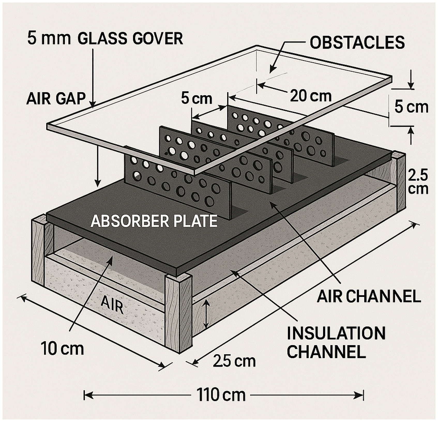
Schematic cross-section of the solar air heater showing (1) glass cover; (2) 5 cm air channel; (3) absorber plate (110 cm × 50 cm × 2 mm); (4) six perforated obstacles (0.5 mm GI, 5 cm high, spaced 20 cm apart) with hole diameters of 2, 3, 4, 5, or 6 cm; (5) lower static-air insulation channel (10 cm high); (6) wooden sidewalls (2.5 cm).
The specifications of Types I–V, which are distinguished based on the hole diameter.
The parameters measured during data collection are:
Outlet air temperature Inlet air temperature Absorber temperature Environment temperature Sun radiation Outlet air speed Pressure drop inside the channel.
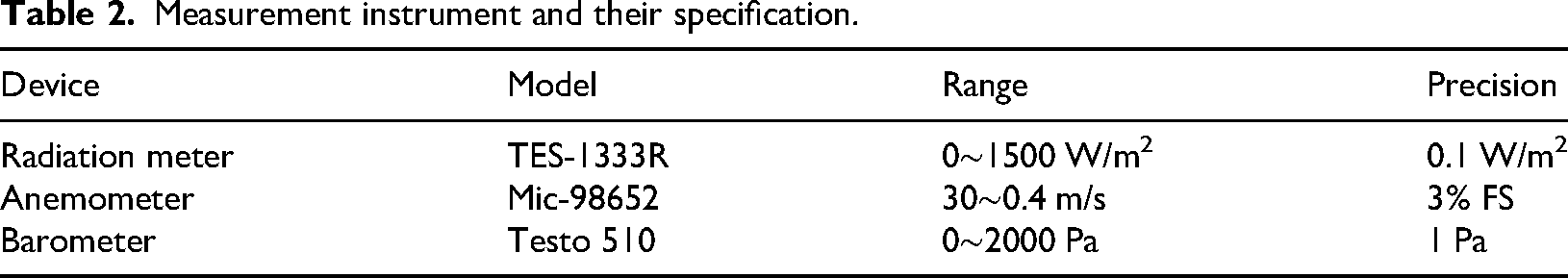
The total solar radiation reaching the collector's surface was measured using a TES-1333R radiation meter. Airflow speed at the collector's outlet was measured with a digital anemometer, Mic-98652. Air was supplied by a centrifugal blower with a maximum power of 550 W (pressure 2400 Pa). DS18B20 sensors were used to measure the inlet (ambient) and outlet temperatures of the collector. The pressure drop across different states in the collector channel was measured using a Digital pressure gauge, Testo 510. The specifications of the measuring devices are shown in Table 2.
Measurement instrument and their specification.
Mathematical analysis of collector performance
In order to assess how well a collector is working, two main factors are important: thermal efficiency and effective efficiency. These values can be calculated using the measurements discussed in the previous section and the mathematical formulas provided.
Knowing the inlet and outlet temperature of the air from the collector, along with the mass flow rate, allows us to calculate the useful heat transferred to the air using equation (1) (Didi et al., 2024; Saravanakumar et al., 2020).
The specific heat capacity of air is represented by Cp. To is the temperature at the outlet of the collector, and Ti is the temperature at the inlet. The air's mass flow rate within the channel can be determined using equation (2):
The speed at the outlet nozzle is determined using an anemometer. The flow is measured using the cross-sectional area (A), which is the same as the outlet nozzle's cross-sectional area. The outlet nozzle is a circle with a diameter of 6 cm.
Instantaneous thermal efficiency (ηth) is defined as the ratio of useful heat to incoming radiation on the surface of the collector (Didi et al., 2024; Saravanakumar et al., 2020):
Note that, in each experimental trial, the air velocity (V) required for equation (3) was measured directly at the collector outlet using a calibrated anemometer (Model: Mic-98652). The anemometer was placed at the center of the outlet nozzle (diameter of 6 cm), and velocity readings were recorded at steady-state operating points. The measured value of (V) was used to calculate both the air mass flow rate and the instantaneous thermal efficiency in accordance with equations (2) and (3).
The presence of obstacles in a collector disrupts the flow and enhances heat exchange with the air, leading to an expected increase in thermal efficiency. However, adding obstacles also increases the pressure drop in the channel, requiring more work from the blower. Therefore, solely evaluating the thermal efficiency of the collector may not provide an accurate analysis, especially as the number of obstacles or mass flow rate increases. To address this, a more reliable parameter that considers the work of the blower is needed. Effective efficiency, which incorporates the role of pump work in efficiency calculations, is proposed as a solution (KhoshAkhlagh et al., 2014; Mohammadi and Sabzpooshani, 2013).
Wp represents the pump work, and Cf represents the conversion factor. The value of the conversion factor is considered to be 0.2 (Dong et al., 2021). The work of the pump can also be calculated from equation (5):
In this case, ΔP represents the pressure decrease within the channel, while ηpm represents the efficiency of the pump motor, which is 0.85 (Gupta and Kaushik, 2009; Mohammadi and Sabzpooshani, 2013).
The blower uses electrical energy to circulate the air inside the collector. The price of electric and thermal energy is usually not the same. About 4, there is no difference between electrical and thermal energy. As a result, it is necessary to consider the effect of energy costs. The real price of all types of energy was estimated from the market price, and the ratio of electrical energy to thermal energy was considered to be 2.35 (Ansari and Bazargan, 2018).
Note that the placement of perforated obstacles on the absorber plate does not directly affect the mass flow rate of air, as this is governed by the blower system used in the experimental setup. However, obstacles significantly influence airflow dynamics. By introducing controlled turbulence and disrupting laminar flow, they enhance heat transfer from the absorber plate to the flowing air, resulting in improved outlet temperatures. The mass flow rate for each experimental condition was externally regulated based on blower power and calculated using the outlet velocity and nozzle cross-sectional area during data collection. Further, prior to commencing the experimental trials, all measuring instruments, including thermocouples, the anemometer, and pressure transducers, were calibrated according to established procedures to ensure the accuracy and reliability of the collected data.
Note that the two selected mass flow rates for testing (0.025 and 0.039 kg/s) were chosen to (a) represent relevant working conditions typically encountered in practical SAH applications and (b) ensure repeatability and measurement accuracy under the given laboratory setup. Preliminary calibration runs confirmed that these values provided both stable airflow and sufficient differentiation in thermal and effective efficiency results. Limiting the study to these two representative values also enabled direct comparison of obstacle configurations under controlled conditions, thereby isolating the effect of design parameters from external influences such as solar irradiance fluctuations or inconsistent airflow profiles. However, other values can be tested and the results compared in future studies.
Uncertainty and error analysis
Ensuring the accuracy and reliability of experimental data is one of the critical aspects of this study. All measurements were carefully conducted using calibrated instruments, and an uncertainty analysis was performed to evaluate possible errors in the recorded values of temperature, air velocity, pressure drop, and solar intensity. This section outlines the sources of error and the estimated uncertainty in the key parameters derived from the experiment. The precision of the measuring instruments used was as follows:
- Thermocouples: ± 0.5 °C - Anemometer for air velocity: ± 0.1 m/s - Pressure Transducer: ± 1 Pa - Pyranometer for solar intensity: ± 2%
Key parameter uncertainties
Temperature difference (Δi): The temperature difference between the inlet and outlet air was a key measured parameter influencing the calculation of the thermal efficiency. The uncertainty in these measurements was derived from thermocouples with a precision of ±0.5 °C. By carefully aligning the readings, the overall uncertainty in the temperature difference was estimated to be ±0.71 °C.
Airflow velocity: The airflow velocity, measured via an anemometer with a precision of ±0.1 m/s, contributed significantly to the calculation of the mass flow rate of air (m˙m˙). Based on the velocities tested in the study (6.6 m/s and 11 m/s), the uncertainty in airflow velocity remained within acceptable bounds, ensuring the reliability of mass flow rate calculations.
Mass flow rate: The mass flow rate of air was calculated using the air velocity, density, and cross-sectional area of the channel. Using the uncertainties from airflow velocity measurements, the estimated error in mass flow rate was ±0.00038 kg/s at the lower flow rate (0.025 kg/s) and ±0.00035 kg/s at the higher flow rate (0.039 kg/s).
Thermal efficiency: Thermal efficiency calculations incorporated the uncertainty in temperature measurements, mass flow rate, and solar intensity. At the maximum thermal efficiency of approximately 85%, the error was estimated at ±2.3%.
Effective efficiency: Effective efficiency also accounted for pressure drop uncertainties due to the use of obstacles. Pressure transducer measurements had an associated error of ±1 Pa. The uncertainty in effective efficiency was estimated at ±3%.
The above uncertainty values indicate that all potential errors remain within reasonable limits, and the experimental data provide reliable and consistent results. The uncertainty analysis highlights the robustness of the measurements and validates the trends and conclusions drawn in this study.
Results
During sunny weather conditions in December from the 9th to the 16th, the performance of the collectors was examined. The increase in efficiency of the collectors was determined using equation (3). The collectors were tested at two different flow rates: 0.025 kg/s and 0.039 kg/s (resulting in outlet velocities from the nozzle of 6.6 m/s and 11 m/s, respectively). Each combination of flow rate and velocity was tested for two days, with the first day having a lower flow rate (0.025 kg/s) and the second day having a higher flow rate (0.039 kg/s).
The heat transferred to the air and the thermal efficiency were calculated using the recorded data for each collector. The results from the laboratory were presented in graphs and tables showing how the temperature inside the collectors increased over time, as well as the thermal and effective efficiency.
Figure 4 displays the hourly changes in radiation during the test days. To make it easier to understand, the radiation values are presented in two separate graphs. Figure 4(a) shows the radiation levels on days when the collector had a lower flow rate, while Figure 4(b) shows the radiation levels on days with a higher flow rate. The peak radiation levels were observed between 12 and 13, which aligns with solar noon.
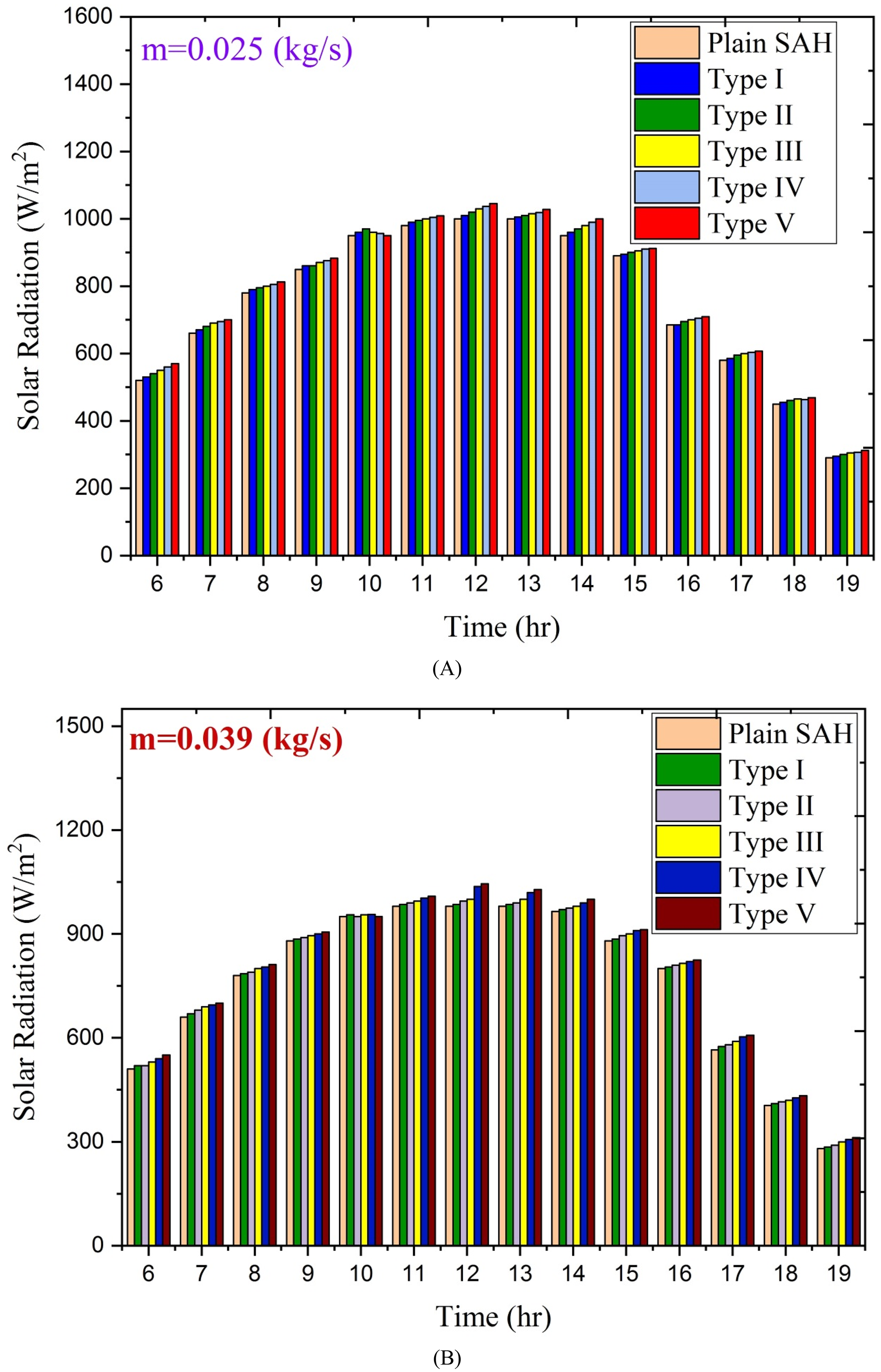
Variation of solar intensities received on the collector surface.
Figure 5 displays a graph showing the temperature difference during test days from 9:00 AM to 4:00 PM for two different mass flow rates. The highest temperature difference occurs around noon, between 12:00 and 13:00. This temperature difference is influenced by both the amount of radiation and the ambient temperature at that time. The largest temperature difference is observed when obstacles with 3 cm diameter holes are placed inside the channel. For this setup, the temperature difference between the air entering and leaving the collector is approximately 17 °C for a flow rate of 0.025 kg/s and about 12 °C for a flow rate of 0.039 kg/s. Generally, the temperature difference is greater at lower flow rates compared to higher flow rates. Lower flow rates allow the air to absorb more heat and increase in temperature. The obstacles in the channel include barriers with 4 cm diameter holes, six barriers with 5 cm diameter holes, and a simple collector. The maximum temperature difference in the simple collector is around 8 °C on the first day (lower flow rate) and around 6 °C on the second day (higher flow rate) around noon. This means that using perforated barriers results in a temperature difference around noon that is up to 2 times higher compared to the simple collector mode. The obstacles force the air to pass through the holes, creating turbulence in the flow. Smaller hole dimensions increase turbulence. The obstacles also act as fins, increasing the surface area for heat exchange with the air and transferring heat to the flow.
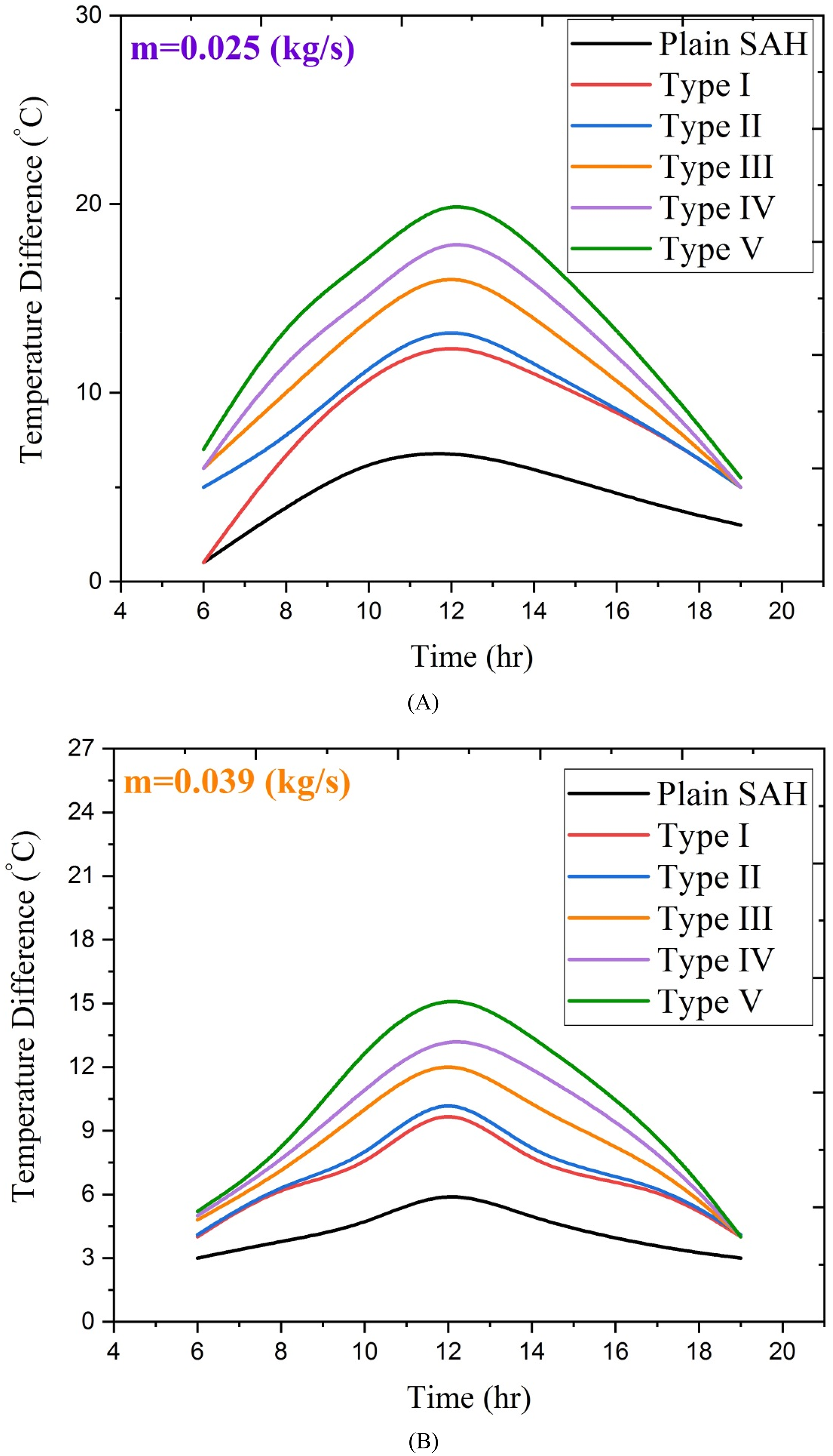
Temperature difference between the inlet and outlet air for the two flow rates.
Figure 6 displays the hourly variations in the thermal efficiency of the collector under four different conditions. The efficiency is higher on the second day of data collection due to the relationship between heat transfer coefficient and speed. When the velocity increases, the Reynolds number of the flow and the heat transfer coefficient also increase. This results in more heat being transferred from the absorbent plate to the fluid, leading to a higher system efficiency. The collector's highest thermal efficiency is seen in the third scenario, with a flow rate of 0.039 kg/s, averaging 85%. At a flow rate of 0.025 kg/s, the efficiency is around 69.5%, showing a 1.22 times increase in thermal efficiency with a higher flow rate. Comparatively, the simple collector has an average thermal efficiency of 35% and 47% at the two flow rates. By using porous barriers, the collector's efficiency has improved by 36% and 41%, respectively, compared to the simple setup. The efficiencies of the first and second types of collectors at a flow rate of 0.025 kg/s are similar, but the difference between them increases with higher flow rates. Despite efficiency being inversely related to radiation, the maximum efficiency is observed during hours with the highest radiation. This is likely due to the maximum temperature difference between the outgoing and incoming air during those hours.
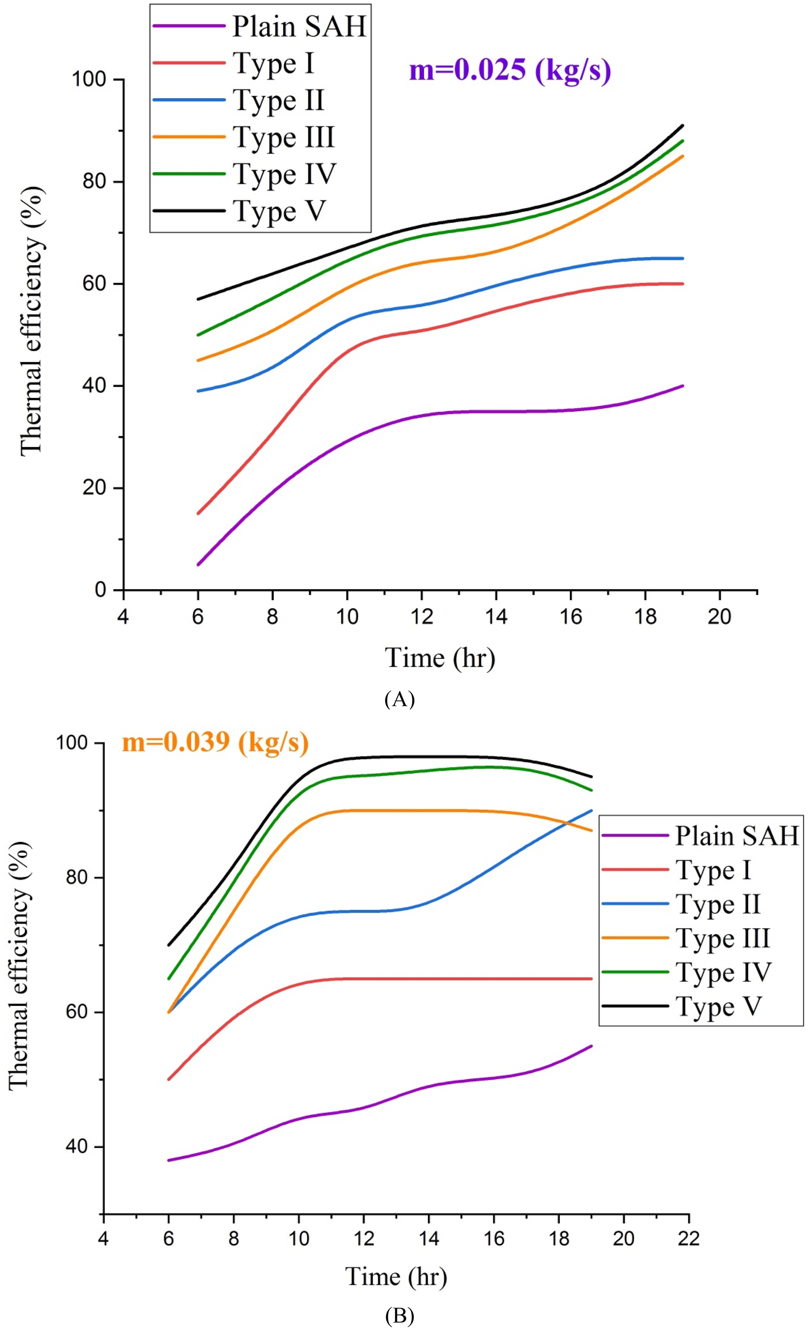
Thermal efficiency of the collector for two flow rates.
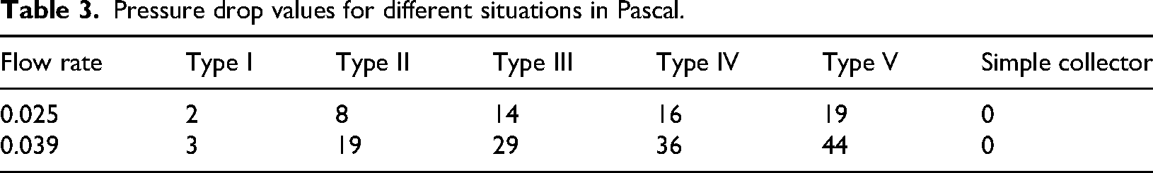
Table 3 displays pressure drop values for various scenarios. By using these values in equation (6), one can determine the effective efficiency. It is important to note that due to the short channel length and slow airflow speed, pressure drop values are not significant, especially in the first scenario. For a basic collector, pressure drop can be calculated using empirical relationships like the Darcy–Weisbach equation. The resulting values for both flow rates will be less than 1 Pa. Since the pressure gauge can measure values lower than 1 Pa, it will display zero.
Pressure drop values for different situations in Pascal.
The results show that the maximum thermal efficiency of the solar air heater equipped with Type V perforated obstacles (2 cm hole diameter) was 85% at a mass flow rate of 0.039 kg/s, and 69.5% at 0.025 kg/s. Correspondingly, the maximum effective efficiency achieved was 36% at 0.039 kg/s and 33.85% at 0.025 kg/s. These results confirm that optimizing obstacle design—specifically through minimizing hole diameter—can significantly enhance both the thermal output and the net useful energy gain, even after accounting for increased pressure losses and blower energy consumption.
To evaluate the impact of pumping losses caused by different obstacle configurations, the pressure drop across the air channel was measured during the experiments using a digital pressure gauge (Testo 510, precision ±1 Pa). Pressure drop values were recorded for all obstacle types and the simple collector at two mass flow rates (0.025 kg/s and 0.039 kg/s). These measurements provide valuable insights into airflow resistance caused by varying hole diameters of the obstacles. Table 3 presents the pressure drop values, which increase with decreasing hole diameter due to stronger flow resistance. For example, at 0.039 kg/s, Type V obstacles (smallest holes, 2 cm) exhibited a pressure drop of 44 Pa, whereas Type I obstacles (largest holes, 6 cm) showed only 3 Pa. Despite the increased pumping losses associated with smaller hole diameters, the enhanced turbulence and heat transfer make this design optimal for improving overall system performance.
The pressure drop values obtained during the experiments clearly illustrate the trade-off between enhanced heat transfer and increased flow resistance in the solar air heater. Smaller hole diameters result in higher pressure drop values, as shown in Table 3, due to the increased turbulence caused by the obstacles. However, this turbulence also promotes improved heat transfer efficiency. The effective efficiency metric was utilized to account for pumping losses, which arise from the blower energy needed to overcome this flow resistance. The results indicate that the Type V obstacles (smallest holes) achieve the highest effective efficiency (36% at 0.039 kg/s and 33.85% at 0.025 kg/s), demonstrating that the net thermal benefit outweighs the performance penalty caused by increased pumping losses.
The enhanced thermal performance observed in the solar air heater configurations featuring perforated obstacles directly implies a significant improvement in the convective heat transfer coefficient between the absorber plate and the working fluid (air). The substantial increase in air outlet temperature and thermal efficiency, especially with smaller hole diameters, serves as compelling experimental evidence of this enhancement. While a direct comparison with precise theoretical heat transfer coefficients is challenging due to the intricate and non-uniform flow patterns induced by the perforated obstacles, which deviate significantly from simplified theoretical models, our results clearly demonstrate that the obstacles are highly effective in disrupting the thermal boundary layer and augmenting heat transfer compared to a smooth channel. The experimental data effectively quantifies the impact of these enhanced heat transfer rates on the overall system performance.
Figure 7 displays the collector's efficiency at various times. Effective efficiency considers the pressure drop in the channel and the pump's necessary work, providing a more accurate representation of the collector's performance.
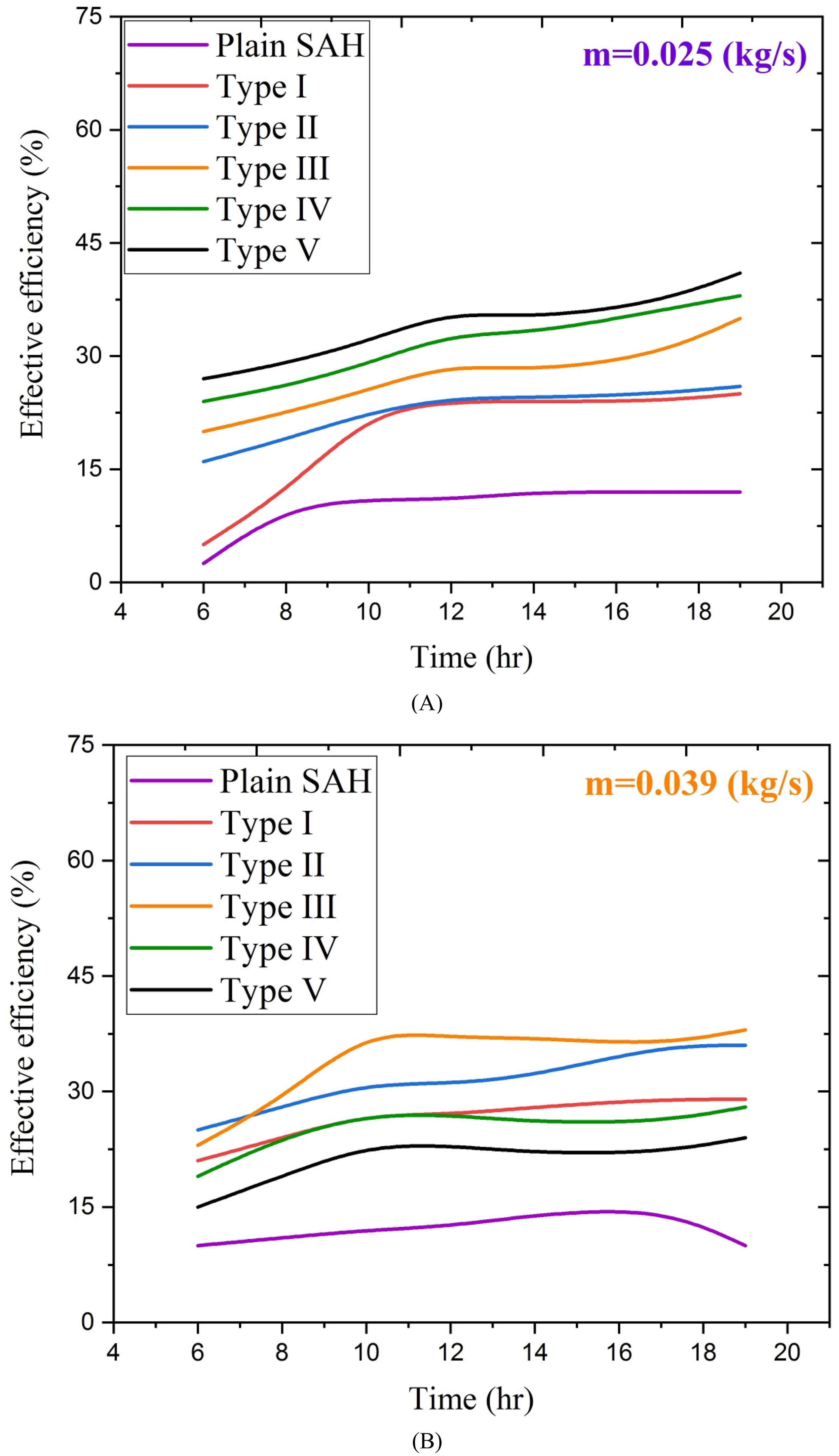
Effective efficiency of the collector for two flow rates.
In addition to thermal and effective efficiency assessments, it is worth examining dimensionless parameters like Reynolds and Nusselt numbers to provide further insight into the fluid flow and heat transfer characteristics. The Reynolds number (Re) represents the ratio of inertial to viscous forces in the flow channel, determining whether the flow remains laminar or transitions to turbulence. In the current study, approximate Reynolds number values ranged from 6200 to 15,000, indicating that flow within the passage likely transitioned to moderate turbulence, particularly at higher flow rates and when smaller holes (Type V obstacles) were used. The perforated obstacles disrupted laminar flows effectively, enhancing turbulence and thus heat transfer. The Nusselt number (Nu) encapsulates the efficiency of convective heat transfer relative to conductive heat transfer. Estimated Nusselt numbers for the experimental setups varied from 35 to 110, with smaller hole diameters contributing to enhanced flow mixing and heat transfer enhancement. This behavior aligns with the observed increases in outlet air temperature and thermal efficiency, as shown in Figures 5 and 6. The role of local turbulence induced by perforations was particularly significant, as it disrupted the thermal boundary layer near the absorber plate, allowing for stronger interaction between the air and the heated surface.
When comparing thermal efficiency and effective efficiency, it is evident that both graphs show a similar trend. As shown in Table 3, the pressure drop increases significantly as the cross-sectional area decreases, impacting the furnace efficiency. The collector with Types V, IV, and III obstacles performs the best in terms of efficiency, followed by Type II, Type I, and finally the simple collector. It is important to note that due to the collector's relatively short length, the pressure drop values, especially in the first and second types, are not significant compared to the absorbed heat. If the correction factor for heat were not applied, there would be no significant change in the efficiency graphs. By applying the correction factor, the collector's efficiency values are adjusted to less than half for different scenarios. The average effective efficiency for a flow rate of 0.039 kg/s is 36% for Type V, 34.71% for Type IV, 34% for Type III, 31.28% for Type II, 26.4% for Type I and 14.2% for the simple collector. Similarly, for a flow rate of 0.025 kg/s, the average efficiency values are 33.85%, 31.28%, 27.14%, 22.5%, 19.5% and 10.07%, following the same order.
Convective heat transfer is central to the thermal performance of solar air heaters. In this study, forced convection between the absorber plate and airflow was augmented by introducing perforated obstacles, which significantly improved the heat transfer coefficient. The turbulence generated by obstacles disrupted the thermal boundary layer near the absorber plate, leading to stronger interaction between the airflow and the heated surface. Experimental results revealed substantial temperature differences between inlet and outlet air—up to 17°C at 0.025 kg/s—indicating enhanced convective heat transfer. These improvements were reflected in the thermal efficiency, which increased to 85% for Type V obstacles at the higher flow rate.
The results obtained in this study demonstrate significant improvements in the thermal and effective efficiency of solar air heaters via the use of perforated obstacles, which are in line with or exceed the findings of previous research. For instance, Saravanakumar et al. (2019) and Ahmed-Zaid et al. (1999) reported thermal efficiency improvements of about 28.3% and 30%, respectively, when using ribbed or arch-shaped obstacles. In comparison, our design with perforated obstacles achieved efficiency increases of 36% at higher flow rates, supported by better heat transfer due to enhanced turbulence. Additionally, the inclusion of perforations addresses the trade-off between thermal efficiency and pressure drop, as highlighted by Handoyo et al. (2016) and Bensaci et al. (2020). The effective efficiency reported in our study (e.g., 36% for Type V obstacles) confirms that perforated barriers provide a viable solution to balance these competing factors.
Few studies, such as Sharma et al. (2019), have explored obstacle shapes for turbulence enhancement, but the specific contribution of perforations in flow dynamics remains largely unexplored in the literature. This study fills that gap by specifically analyzing the relationship between obstacle design parameters (e.g., hole diameter) and collector performance, contributing new knowledge to the field.
Figure 8 compares the measured thermal efficiency at two representative mass flow rates from the present study with corresponding literature values reported by Mohammed et al. As evident, the two datasets demonstrate excellent agreement at both flow rates, supporting the robustness of the present experimental protocol. Minor deviations (below 3%) are within the expected range of experimental uncertainty.
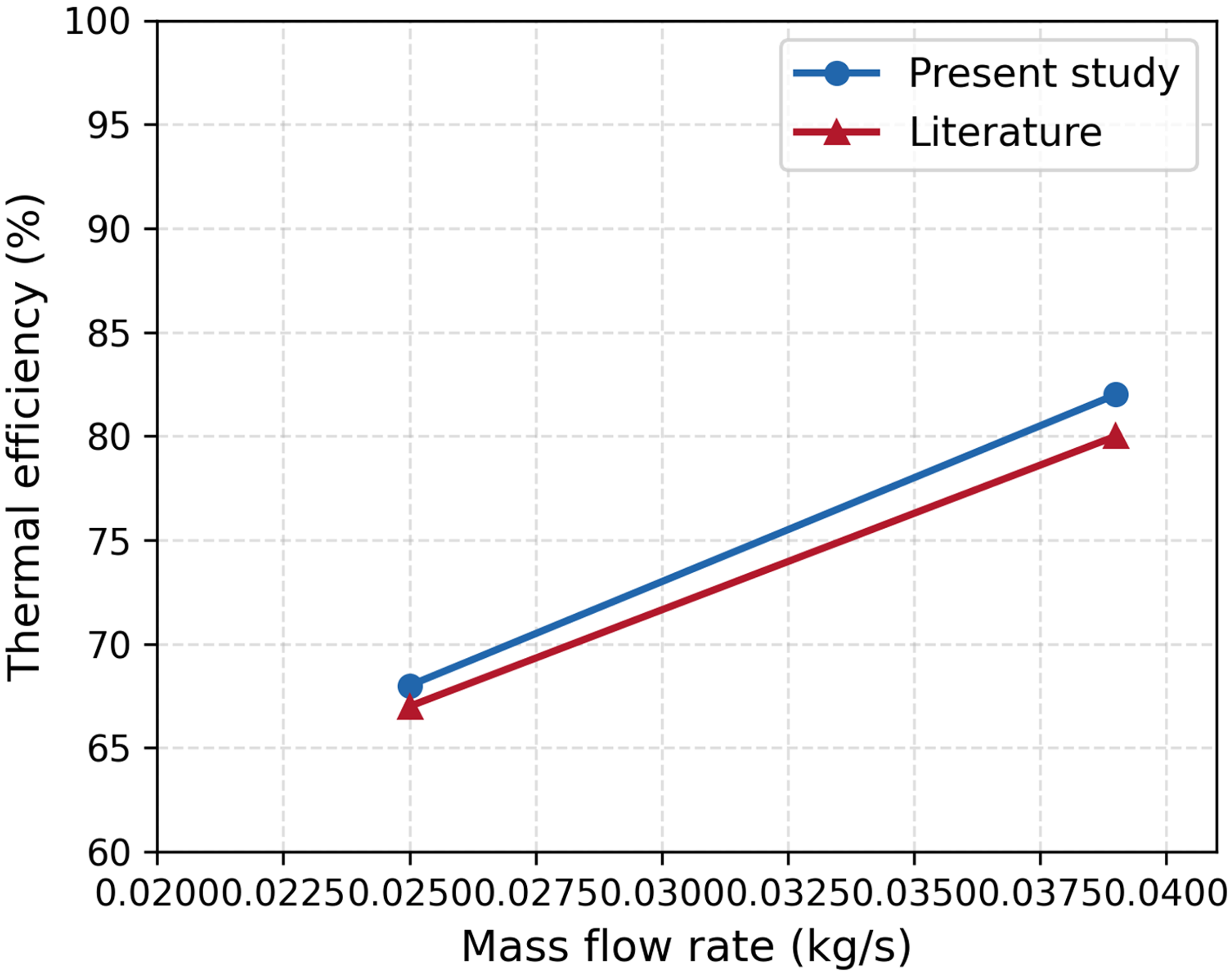
Comparison of thermal efficiency versus mass flow rate for the present study and Chabane et al. (2018).
Discussion and conclusion
This experimental investigation successfully demonstrated the significant potential of incorporating perforated obstacles on the absorber plate to enhance the thermal performance of a solar air heater. The study systematically explored the impact of varying obstacle hole diameters and mass flow rates on key performance indicators, including thermal efficiency, effective efficiency, and pressure drop. The findings conclusively indicate that the introduction of these obstacles induces turbulence within the air channel, leading to a substantial improvement in heat transfer between the absorber plate and the working fluid.
Other notable outcomes of this research are summarized as follows:
Thermal efficiency increases with mass flow rate; at 0.039 kg/s, the solar air heater with Type V obstacles (smallest hole diameter, 2 cm) reached a maximum efficiency of 85%, a 36% improvement over the simple collector. At a lower flow rate of 0.025 kg/s, the Type V configuration maintained a thermal efficiency of 69.5%, showing a 33% enhancement compared to the simple design. Perforated obstacles are effective in disrupting the boundary layer and enhancing convective heat transfer. Implementing obstacles, especially with smaller hole diameters, increases pressure drop; however, the resulting improvement in heat transfer compensates for this drawback. The effective efficiency analysis, accounting for pressure drop and pumping power, showed that Type V obstacles still provided the highest net efficiency (36%) at higher flow rates. Optimizing obstacle design (hole diameter and configuration) is crucial for maximizing the overall efficiency of solar air heaters, balancing heat transfer enhancement against increased pumping losses.
In summary, this study provides compelling experimental evidence that strategically placed perforated obstacles on the absorber plate are a viable and effective method for optimizing heat transfer and airflow dynamics in solar air heaters. The results highlight the trade-off between enhanced heat transfer and increased pressure drop, emphasizing the importance of obstacle design parameters for maximizing overall system performance. Future research could focus on optimizing obstacle geometry and placement to further enhance effective efficiency and explore the long-term performance and durability of such modified solar air heaters.
Footnotes
List of symbols
Acknowledgements
This research is funded by Zarqa University.
Funding
The authors disclosed receipt of the following financial support for the research, authorship, and/or publication of this article: This work was supported by Zarqa University.
Declaration of conflicting interests
The authors declared no potential conflicts of interest with respect to the research, authorship, and/or publication of this article.