
Abstract
When converting electricity by general-purpose reciprocating engines, regulations on emission composition are set in all regions. These regulations apply even in the case of using bio-syngas, a renewable energy source, as a fuel. Therefore, the conditions in which NOx and CO satisfy the environmental regulation values are experimentally examined by varying the LHV in this paper. The nitrogen, hydrogen, and methane ratios in the bio-syngas were varied to change the LHV. The results are as follows: 1) The NOx volume fraction in the exhaust gas was higher than the NOx regulation value in all cases of operation with any gases. After-treatment systems should be installed to purify the exhaust gases. 2) Under the lean-burn condition, the CO volume fraction in the exhaust gas is negligibly small and satisfies the environmental regulation value.
Keywords
Introduction
Effective use of biomass for Japan
In recent years, renewable energy use has been promoted. International Energy Agency (IEA) bioenergy (2024) reports that biomass energy has high potential as an energy supply source on a global scale. In 2020, 12.6% of total final energy consumption is from biomass. The estimated amount of sustainable biomass energy in 2050 is 100 EJ, which is enough potential to supply the biomass energy demand in the same year. Effective use of biomass energy in Japan as an energy supply source is also desirable.
New Energy and Industrial Technology Development Organization (NEDO) (2023) classified the biomass in Japan into waste biomass resources, such as factory residues, manure, and wastes. Unutilized resources include thinned wood and wheat straw, while grass, algae, and oil are productive resources. Forest residues, thinned and unutilized trees, and wastepaper have the highest potential in the NEDO report. Most wastepaper is reused. On the other hand, forest residues, thinned wood, and unused trees are not effectively reused, so the biomass available is high. It is necessary to discuss what kind of energy conversion devices are appropriate for Japan to promote the use of resources that have not been effectively used to this day.
Biomass acts as a device to fix atmospheric carbon dioxide. This fixed energy is typically used for power generation by 1) direct combustion and 2) gasification. Badshah et al. (2020) reported an example of power generation using the steam Rankine cycle with steam produced by direct combustion. On the other hand, the gasification method is widely used for operating gas turbines and gas engines. From these power generation methods, it is important to consider the following two points for effective methods to be taken in Japan. First, Japan belongs to the tropics and is strongly affected by typhoons. As a result, natural disasters occur frequently, causing various logistics disruptions. Second, Japan has many forests located in narrow mountainous areas, which increases the transportation distance to large-capacity power generation facilities, which are installed in areas close to the coastline. As a result, CO2 emissions during transportation cannot be ignored. Therefore, an effective solution is to install power generation facilities with independent, small-scale fuel supply sources in each region.
Ministry of Economy, Trade and Industry (METI) (2023) estimates also show that transportation costs dominate among woody biomass fuel costs. The main reasons for this are 1) low forest density, 2) mountainous terrain, 3) poor road network, and 4) low installation of high-performance forestry machinery. From the standpoint of the cost of procuring fuel for power generation, gasification methods should be combined for biomass power generation in small areas. In view of the price at installation and maintenance cost, a general-purpose reciprocating engine for power generation is effective for the equipment used for power generation; Costa et al. (2020) reported that the general-purpose spark-ignition reciprocating engine (GP-SIRE) is easy to operate and is expected to make effective use of biomass resources.
Structure of the woody biomass gasifier for gas engine power generation
When woody biomass is used as fuel for a GP-SIRE, the fuel properties are liquid or gaseous. Hoang et al. (2021) reviewed that 75% of the calorific value of the input woody biomass is extracted as a liquid in the fast (fast pyrolysis) process. However, it contains a large amount of water, so additional modifications are required as engine fuel (averaged) (Rahman et al., 2020). Conversion of woody biomass into gas is more appropriate for power generation, as conversion efficiency is an important index. Therefore, the GP-SIRE is a reasonable way to use this gaseous fuel. In this paper, the combustible gas obtained from the gasification of woody biomass is defined as the bio-syngas.
Gasifiers for small-capacity power generation systems have a small reaction area. Therefore, it is necessary to select a reaction system that meets the required capacity. The main types of gasifier reaction systems are 1) fixed-bed type, 2) moving bed type, 3) fluidized-bed type, and 4) entrained bed type. All are self-heating. In the moving bed type, the fuel is moved through the reactor by a mechanical structure. In the fluidized-bed and jet-bed types, the oxidizer flow conveys the fuel. The fixed-bed type, on the other hand, has the advantage of small size and low manufacturing cost, although the fuel properties that can be selected are limited (Situmorang et al., 2020). Therefore, it is reasonable to select the fixed-bed gasifier.
The fixed-bed gasifiers exhaust tar as well as the product gas. Tar is defined as “the organic matter that is generally almost all aromatic and produced during the pyrolysis or the gasification of the organic matter” by Milne et al. (1998). Tar is highly viscous at room temperature and is the cause of equipment blockages and failures. Milne reports that the tar concentration of the bio-syngas supplied to the small GP-SIRE is recommended to be between 10 mg/Nm3 and 100 mg/Nm3 to prevent mechanical structure failure.
The fixed-bed gasifier is classified into downdraft and updraft types and differs in the direction of the oxidizer flow. The updraft type allows the oxidizer to flow from below the fuel, and the downdraft type allows the oxidizer to flow from above. The downdraft type has the advantage of low tar emissions (Cortazar et al., 2023). Therefore, the fixed-bed downdraft gasifier is suitable for producing the fuel for the small GP-SIRE.
Synthesis gas is a synthetic gas with a 1:1 mixing ratio of H2 to CO by volume. It is mainly produced chemically from CH4 and CO2 (Mohanty et al., 2021). On the other hand, bio-syngas is a mixture of H2 and CO as the main combustible species, the same as general syngas. However, because it is self-heating and uses air as an oxidizer, it contains more than 50% N2 and 10% CO2. As a result, the lower heating value (LHV, [MJ/Nm3-LHV]) of bio-syngas ranges from 2.69 to 5.39 MJ/m3-LHV (Sidek et al., 2020). These values are approximately 1/10 of those of conventional fossil fuels. In contrast to bio-syngas, digestion gas, which is produced through a fermentation process, has a larger LHV. Digestion gas is a combustible gas produced by methane fermentation of organic matter such as sewage sludge, and its main components are CH4 and CO2. Kim et al. (2016) report that the methane content is about 50%–70% and the LHV is about half that of conventional fossil fuels. This also indicates that, compared to digestion gas, bio-syngas have a large inert gas ratio and a much smaller LHV.
Necessity of LHV adjustment
Przybyła and Nadaleti (2020) study the relationship between the LHV of synthesis gas and the indicated mean effective pressure
Since wood biomass power generation systems use air as the oxidizer, seasonal changes in temperature will alter the concentration of the oxidizer. As a result, the output changes. In the case of Suzu City, Ishikawa Prefecture in Japan, the lowest average winter temperature is −0.8 °C and the highest average summer temperature is 30.3 °C. The temperature difference between winter and summer changes the oxidizer concentration by about 15%. In response to this change in oxidizer concentration, GP-SIRE can be used as a stable base power source by achieving the same output in either season. On the other hand, GP-SIRE is also expected to be a variable response power source because of its short response time to power changes. Generally, when GP-SIRE responds to load variations, the engine speed is changed. However, in the case of power generation, extreme fluctuations in engine speed place a large load on the alternator, resulting in poor power quality. Therefore, LHV change of biogas is effective to scope with this load variation. The following two methods are effective for changing the LHV of biogas: 1) adding CH4 or H2, which have less environmental impact, and 2) changing the oxidizer for gasification.
In this paper, we use 1) H2-doped bio-syngas (fuel with H2 added to bio-syngas), 2) CH4-doped bio-syngas (fuel with CH4 added to bio-syngas), and 3) upgraded bio-syngas. Upgraded bio-syngas is syngas when the oxidizer for gasification is oxygen-enriched air (a mixture of oxygen and nitrogen with a higher ratio of oxygen than air). The O2 concentration of oxygen-enriched air in this experimental apparatus is not 100%-O2, so it is denoted by adding -quasi after the O2 designation, i.e. O2−quasi.
There are three advantages of oxygen-enriched air to produce the upgrade bio-syngas. First, since N2 in the air is an inert gas, a decrease of the N2 ratio in the bio-syngas increases the LHV as shown in Wang et al. (2015). As a larger LHV increases the output of the power generator, the unit cost of the system reduces. Second, the gasification reaction proceeds when combustible gases and volatile components generated by the pyrolysis of woody biomass react with an oxidizer. Wang et al. (2015) report that the increase in the concentration of O2 in the oxidizer raises the temperature of the reaction zone. The increase in temperature increases the chemical reaction rate, which is explained by the Arrhenius-type chemical reaction equation. Therefore, increasing the O2 concentration leads to a higher gasification rate of the woody biomass and a smaller reaction zone. Third, the increase in the temperature of the reaction zone promotes the thermal decomposition of the tar. Consequently, Galindo et al. (2014) report that tar emissions have the potential to be reduced.
Exhaust gas from reciprocating engines operating with bio-syngas and three different bio-syngas mixtures
The CO2 emissions in the exhaust gas from the GP-SIRE operating with the bio-syngas are absorbed during the growth of the wood which becomes the fuel for the bio-syngas. Therefore, CO2 emissions from the engines are assumed to be circulating. However, the GP-SIRE operating with the bio-syngas emits environmental pollutants such as CO, NOx, and HC. These pollutants, which cause environmental and health problems, should be reduced. Legal regulations have been established to reduce the environmental impacts and health problems caused by exhaust gas. The main environmental pollutants regulated are HC, soot, NOx, and CO. The main hydrocarbon composition in the bio-syngas is methane, which is at most 2 v%. Therefore, the HC ratio in the exhaust is very small, less than 20 ppm. Shah et al. (2010) operated the GP-SIRE with the bio-syngas. They reported that HC in the exhaust gas was less than 40 ppm. Similarly, since the bio-syngas contain almost no aromatics, the soot is also hardly emitted. Consequently, when operating the GP-SIRE with the bio-syngas, the emission rates of NOx and CO should be validated to comply with the environmental regulations.
The emission composition from the GP-SIRE operating with the bio-syngas with H2, the bio-syngas with CH4, or the upgrade bio-syngas require compliance with legal regulations established in each region. According to the Environmental Standards for air pollution and odor related standards, by the Bureau of Environment of Tokyo Metropolitan Government (2021), NOx emission regulations have been established for power generators. The allowable NOx ratio in the exhaust gas from the gas engine is 500 ppm-NOx. For the CO ratio, there is only a standard for CO concentration in the air around exhaust gas generating facilities. If the emission standards for transportation vehicles are applied to power generation engines, the emission standard will be 0.5 v%-CO.
The purpose of this paper is to propose conditions under which NOx and CO in the exhaust of a GP-SIRE become small even when the LHV and excess air ratio (EAR) of the bio-syngas are adjusted to achieve the objective. The LHV of the bio-syngas was adjusted by 1) changing the O2 concentration of the oxidizer in a self-made gasifier and 2) mixing the bio-syngas with H2 or CH4 (city gas 13A is substituted instead in this paper). As a result, the LHV of the gaseous fuel to operate the GP-SIRE reached 6.6 MJ/m3 at maximum.
Experimental apparatus
Gasification system
A self-made gasifier is used for the experiment. The gasifier is supplied with easily available whole cedar pellets. The pellets are 6 mm in diameter, 15 mm long, and have a moisture content of 8.0 w%. The pellets are supplied from a pellet holder to the reactor by a screw.
The gasifier is designed so that a blower (4LM310-H16) installed at the downstream of the gasifier creates negative pressure throughout the reaction path (Figure 1). The flow rate of the oxidizer is measured by a self-made Venturi flowmeter. The oxygen concentrator used in this experiment (maximum flow rate of 10 L/min, outlet O2 concentration 90 v%±3) produces oxygen by separating oxygen and nitrogen from air. The O2 concentration measured by gas chromatography (Agilent Technologies 490 Micro GC) was approximately 87 v%.
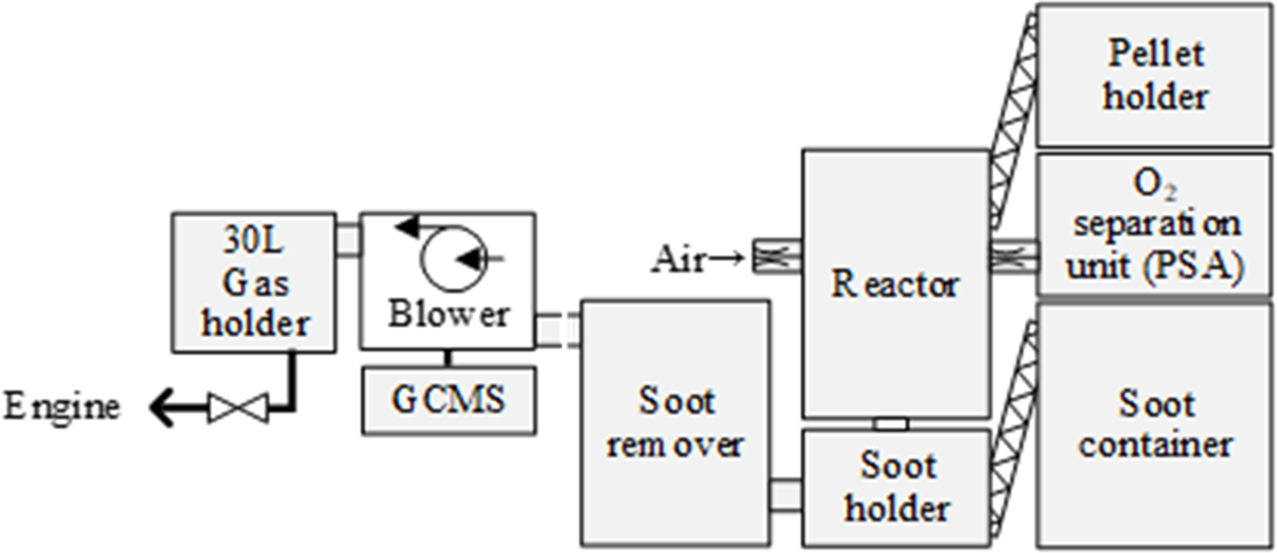
Schematic of gasification system.
The inner diameter of the reactor used in this experiment is 102.3 mm. The reaction zone is divided into four main sections. The oxidizer flow rate is kept constant, and the pellet height in the reaction zone is detected by a level installed in the reactor. The pellet is fed so that the pellet height is kept constant at 195 mm. A grate fixed in the reactor supports the pellets. If the oxidizer is O2−quasi, it is fed at 90 mm from the bottom of the pellets. If the primary oxidizer and O2−quasi are mixed and fed from the top of the reactor, the gasification reaction rate of the pellets increases excessively, and the pellets instantly turn to ash. As a result, clogging of the reactor occurred frequently. Therefore, in this paper, O2−quasi is fed at the 90 mm position.
The bio-syngas composition produced in the gasifier is measured by gas chromatography (Agilent Technologies 490 Micro GC). The bio-syngas is removed by a moisture removal system. The columns for the gas composition analysis of H2, N2, O2, CH4, and CO are Molsieve 5A 10 m and PoraPLOT Q 10 m.
When woody biomass is gasified, solid soot, water vapor, and tar are produced simultaneously with the bio-syngas. For soot removal, recycled glass gravel with a diameter of approximately 20 to 30 mm is placed to separate the gas and solid. Mist removal lowers the temperature of the gas with flowing cooling water and removes water vapor and tar as a drain. The pressure of the gas is lowered through an orifice in the condenser after the mist removal, and the water vapor and tar are extracted as the drain. The pressure of the gas is lowered through an orifice in the condenser after the mist removal, and the water vapor and tar are extracted as the drain. Therefore, a paper filter installed downstream of the condenser removes soot again.
The LHV of biogas can be controlled by varying the O2 volume fraction in the oxidizer (Figure 2). The total oxidizer flow rates were 40, 50, and 60 NL/min; the O2 flow rates were 0, 3, 6, and 10 NL/min. When the total oxidizer flow rate (mixture of air and O2−quasi air) is 60 L/min, the reactor temperature is highest and the gasification reaction rate of the pellets increases. On the other hand, comparing the conditions with 21 v%-O2 and 25 v%-O2 in the oxidizer, the LHV hardly changes. This indicates that the LHV of bio-syngas changes significantly under conditions where the O2 volume fraction in the oxidizer exceeds 25 v%. It is very interesting that this threshold of 25 v% for the O2 volume fraction to change the LHV significantly. We will discuss it in the next report.
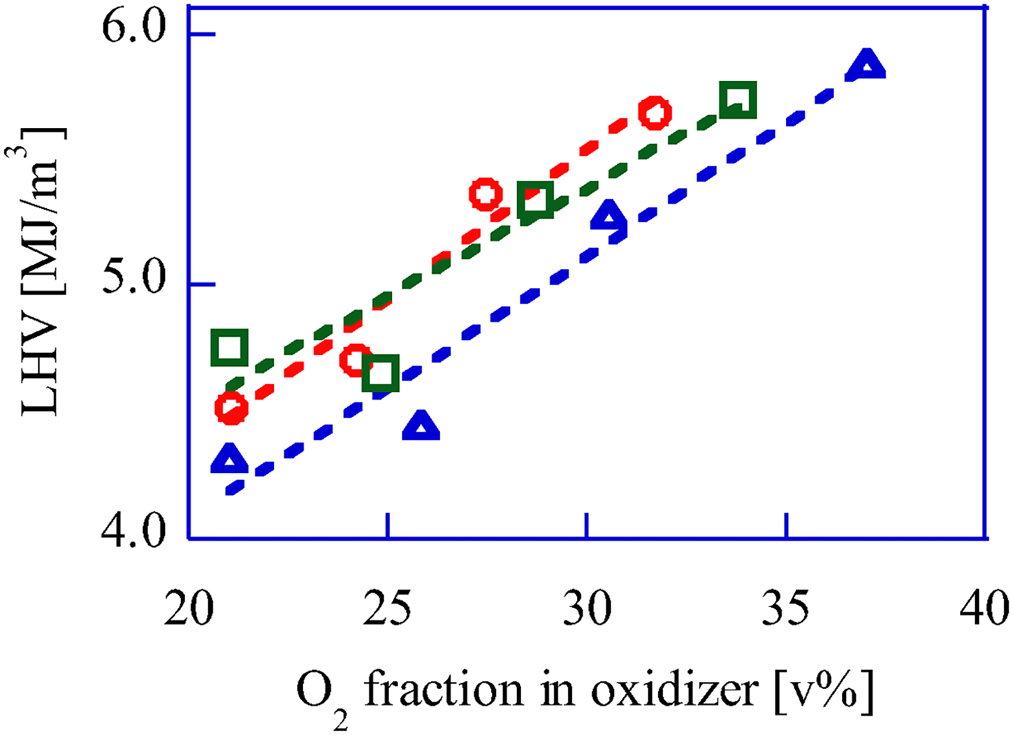
Upgrade bio-syngas LHV change by O2 fraction control in oxidizer. Total oxidizer flow rate, 〇: 60 L/min, □ 50 L/min, △ 40 L/min.
GP-SIRE
The engine specifications in the experiment are in supplement (Table S-1). A general-purpose V-twin cylinder engine was converted to a single-cylinder drive to prevent variations in the intake airflow mixture for each cylinder. Remove the pushrods that operate the intake and exhaust valves to prevent one cylinder from doing the work. The details of the experimental setup are in Enomoto et al. (2024).
H2 or CH4 is added to the fuel, H2 is supplied from a cylinder, and CH4 is supplied by city gas (13A) as an alternative. The flow rate is adjusted with a needle valve. The flow rate of the added fuel was measured by a thermal mass flow meter (azbil CMS0050). The bio-syngas and H2 or CH4, produced in the gasifier, flow from each fuel feed line to a 30 L buffer tank.
The intake air flow rate of the GP-SIRE is measured by a laminar flowmeter (Sokken LFE-25B) and is changed by electronic governor (Woodward LC-50). The governor controls the valve opening with PID to maintain a constant engine speed for the GP-SIRE. This electronic governor operates by PID control of the governor opening to maintain a constant engine speed for the GP-SIRE. Intake air and the fuel which passed through the buffer tank are supplied to the GP-SIRE through a gas mixer.
An eddy current dynamometer (EWS-150-L, Tokyo Meter Co., Ltd) is to measure the power and speed of the GP-SIRE. The load of the dynamometer is controlled by an automatic dynamometer controller (EDC-280-ZX, Tokyo Meter Co., Ltd).
For a spark plug and in-cylinder pressure sensor of the GP-SIRE, 6118CF-5CQ03S4-2 by KISTLER is used. Ignition timing is controlled by an ignition timing controller (Altronic, CD200D). In-cylinder pressure of the GP-SIRE is recorded by a combination of an in-cylinder pressure sensor and a charge amplifier (5018A) by KISTLER. For the data analysis, a memory recorder (DL850) by Yokogawa Electric Corporation and engine combustion analysis software (720340) are used. For the memory recorder, a charge amplifier, and a multiplier for crank angle measurement (Atsense Corporation, CPM-100) are connected to the memory recorder. The in-cylinder temperature is calculated based on the equation of state, assuming complete combustion of the fuel (see Supplemental Material). Therefore, the validity should be examined. Figure 3 shows the measured A: pressure, B: heat generation rate, and C: in-cylinder temperature. The estimated in-cylinder temperature in this figure is almost the same as the in-cylinder temperature obtained by Kan et al. (2018) in a CFD simulation by KIVA4. Therefore, the calculations in this paper are appropriate.
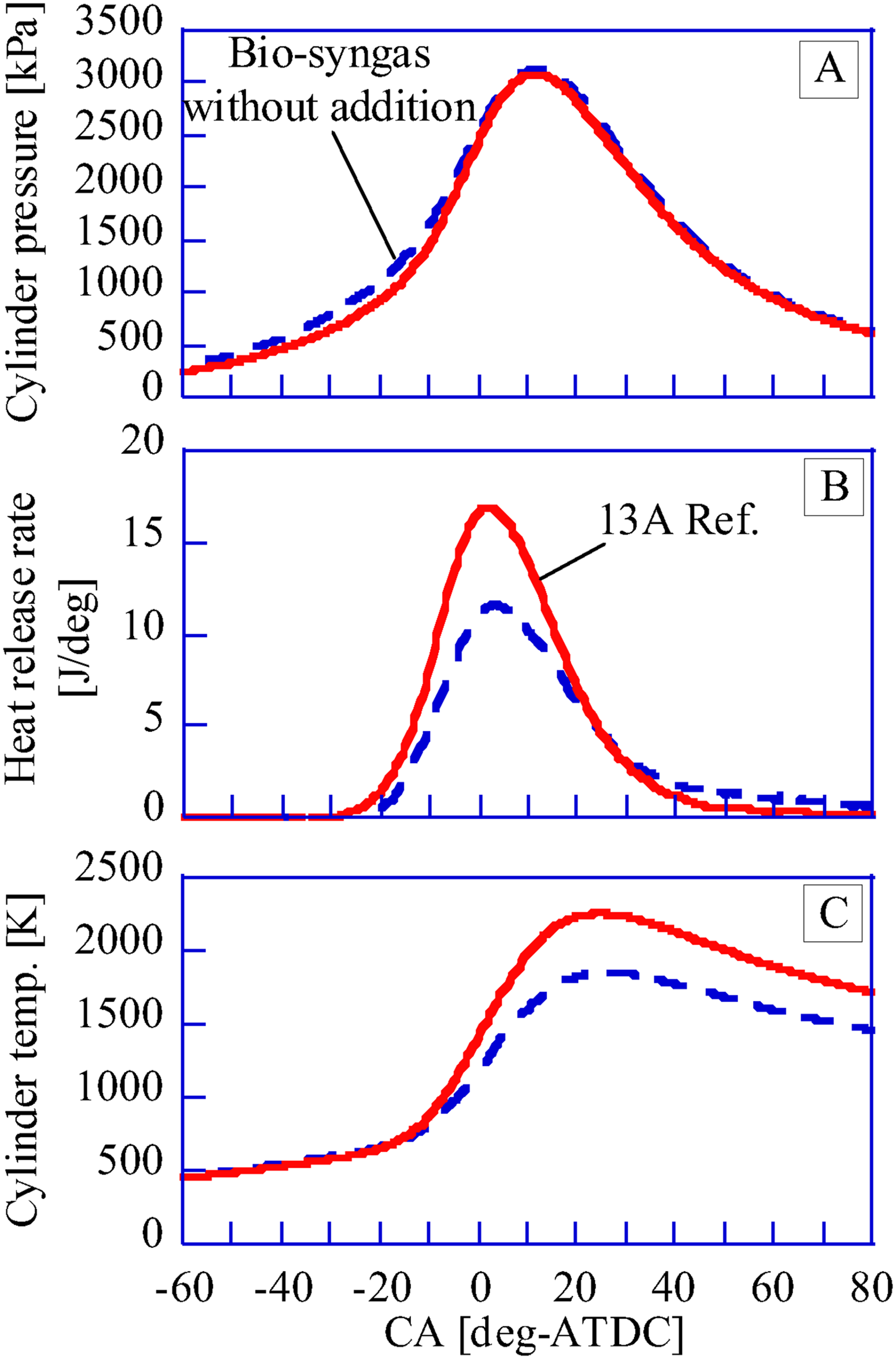
Time histories of cylinder pressure and derivatives.
A commercial radiator (FD750D) is for cooling the GP-SIRE. A flow meter (TOFCO, HF-GCT40-01-30-04) is for measuring the cooling water flow rate. Cooling water is circulated by an electromagnetic pump, and the temperature is maintained by the inlet cooling water at a constant range of 80 ± 2 °C with the circulator.
For measuring the volume fraction (NOx, HC, CO, CO2) in the exhaust gas of the GP-SIRE, HORIBA and MEXA-584L are used. Moisture in the exhaust gas is removed by a drain separator.
Experimental conditions
Experimental conditions
A Kawasaki Heavy Industries FD750D converted to a single cylinder is used as the GP-SIRE. The fuel flow rate supplied is adjusted so that the air excess ratio is 1.6 ± 0.1. In the fuel flow rate adjusting, the oxidizer flow rate for the gasifier is adjusted to use the produced bio-syngas fully. Preliminary experiments show that when the gaseous fuel contains bio-syngas, the indicated thermal efficiency is maximum at an air excess ratio of 1.6 ± 0.1 or higher. On the other hand, when operating with CH4, engine stalls frequently in the fuel-lean region. Therefore, when CH4 is supplied to GP-SIRE, the EAR is 1.0 ± 0.1.
The GP-SIRE ignition timing range is ±3.0 deg relative to the crank angle (CA, [deg-ATDC]) at which the heat release rate (HRR, [J/deg]) is maximum. On the other hand, setting the ignition timing within this range allows for stable power output, which is required for the power generation system. This means that the COV-IMEP should be smallest (Figure 4(a)). In this case, the indicated thermal efficiency shown varies by approximately 2 points (Figure 4(b)). The detailed ignition timing method for GP-SIRE using biogas is described by Enomoto and Saito (2020).
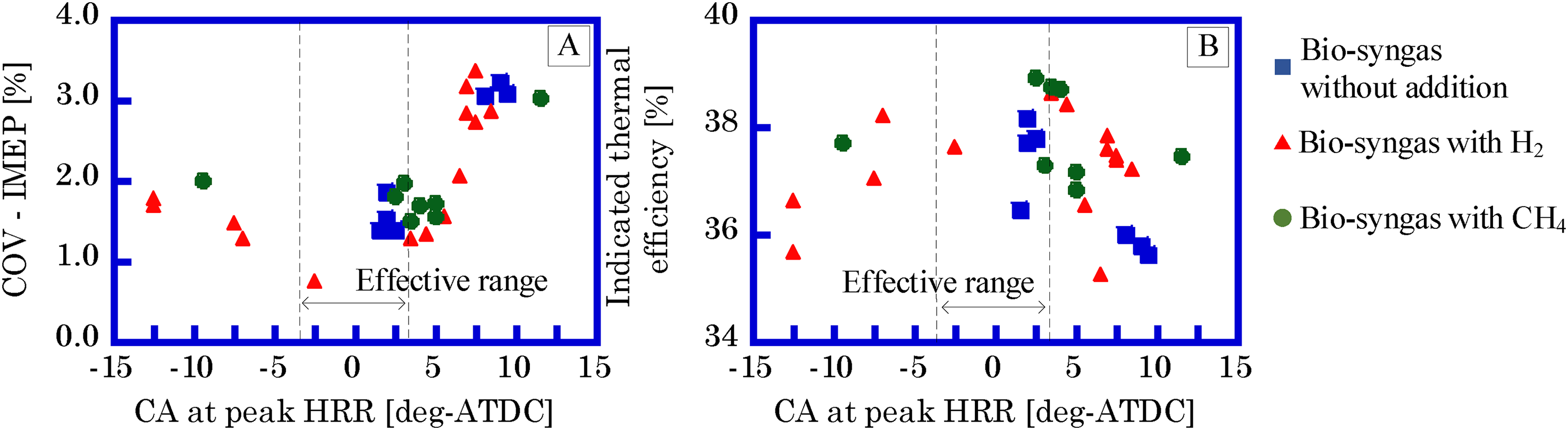
COV-IMEP (a) and indicated thermal efficiency (b) dependence on CA at peak HRR. IMEP: covariant of indicated mean effective pressure.
In accordance with JIS B 8009-5, the engine speed shall be 1800 ± 22.5 rpm. JIS B 8009-5 specifies the standard for a single-cylinder or two-cylinder GP-SIER as a power generation system. In this standard, the rotation speed variation is determined by the steady-state frequency rate of change. Therefore, the allowable rate of change is determined to be 2.5% for the same application as a commercial power supply with voltage specifications.
Analysis conditions
Chemical reaction calculation based on kinetics is used in this paper to consider the combustion in the cylinder. In the case of C2 gas fuel, GRI-Mech 3.0, Aramco mech 3.0, and Foundational Fuel Chemistry Model (FFCM-1, Smith et al., 2016) are representative reaction sets, so a suitable reaction set is selected. The more reaction equations included in a reaction set, the more the chemical reaction based on elementary reactions is accurately reproduced. However, in the case of many reaction equations, the time and effort required for analyses increases. Aramco-mech contains 3037 reaction equations. A reaction set consisting of fewer reaction equations should be used if the calculation results are valid. Considering that the reaction sets are normally described to match the measured laminar combustion rates, the laminar combustion rates of the three reaction sets are calculated and the differences are verified. The composition of the mixture of the GP-SIRE operating with the bio-syngas under the conditions of EAR 1.3 is assumed as CH4: 1.01 v%, CO: 6.86 v%, CO2: 6.35 v%, H2: 7.66 v%, H2O: 0.62 v%, N2: 65.75 v% and O2: 11.74 v%. Initial pressure and temperature are calculated at 500 kPa and 500 K, respectively. The results show that FFCM-1 is about 1.4% smaller and GRI-Mech is about 16% smaller than the laminar combustion velocity by Aramco-mech. FFCM-1 is reported to be more accurate than GRI-Mech by Varghese et al. (2019). For these reasons, FFCM-1 is selected in this paper. The chemical reaction calculations are performed assuming that the premixed air in the GP-SIRE is completely mixed in the mixer in the intake manifold. CHEMKIN is used as the software for chemical reaction calculations, and 0-D homogeneous premixture is selected as the calculation model in CHEMKIN.
Combustion in an ideal Otto cycle is that with infinite flame spread velocity. Therefore, the cycle realized in GP-SIRE approaches the ideal Otto cycle by increasing the flame spread velocity in the cylinder. However, it is difficult to measure the flame spread velocity in the cylinder. As a result, laminar combustion velocity is used to evaluate the flame spread velocity in the cylinder. In general, when evaluating flame spread speed with laminar combustion velocity, the turbulence intensity of the combustion field is considered (Varma et al., 2021, Figure 5). The vertical axis of Figure 7 shows the ratio of turbulence intensity u’ to laminar combustion velocity SL. The horizontal axis of Figure 7 shows the flame structure as the ratio of the representative radius l of the vortex causing turbulence and the preheater thickness δZ of the laminar flame. In the wrinkled and corrugated flame ranges, the flame structure is microscopically wrinkled based on laminar combustion. In the distributed reaction zone and in the thinner reaction zone, strong turbulence disturbs the wrinkled flame. As a result, the basic flame structure is quite different from that of laminar combustion. Therefore, for flames in these zones, an argument based on laminar combustion is not possible, and experimental results using actual engines are needed.
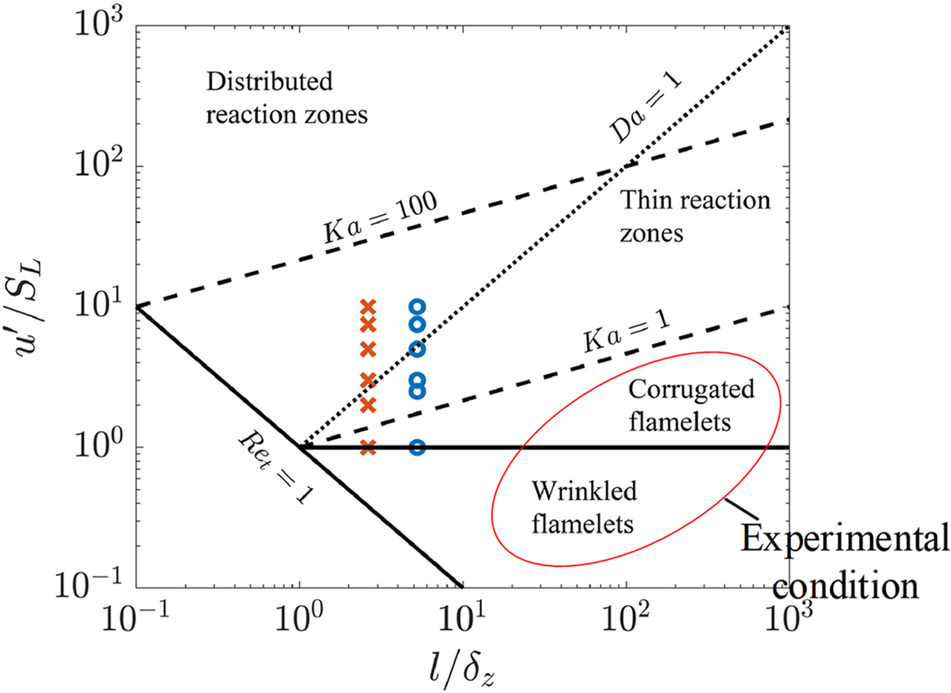
Flame structure as a function of u’/SL and l/δZ (Varma et al., 2021).
For reciprocating engines, the flow in the cylinder may be strengthened to shorten the combustion period and improve thermal efficiency. In the case of commercial transporter engines, intake ports and piston tops have complex shapes in order to strengthen the tumble (longitudinal vortex) and swirl (transverse vortex) in the cylinder. In particular, at the end of the compression process, the average velocity in the cylinder without tumble and swirl flow is about 1/3 of that with tumble and swirl flow (Okura et al., 2013). On the other hand, the engine in this experiment is a GP-SIRE with a flat piston top. Therefore, in-cylinder flow acceleration was not employed in this experiment. When the laminar combustion velocity of bio-syngas is about 33 cm/s-SL (Varghese et al., 2019), the u'/SL of the GP-SIRE in this experiment is about 1, based on the results of Okura et al. (2013). Thus, the flame propagation of GP-SIRE is in the range of wrinkled and wavy flames. This result was also reported by Abraham et al. (1985) and Namazian et al. (1980). These results suggest that more experimental results are needed for GP-SIRE flames, since their basic structure is a wrinkled structure based on laminar combustion.
Results and discussion
Volume fraction of NOx and CO in exhaust gas
Figure 6 shows the NOx volume fraction in exhaust gas to the IMEP and the maximum in-cylinder temperature. The operating condition for the GP-SIRE is the IMEP of 0.60 ± 0.01 MPa. The EAR is 1.0 ± 0.1 for the CH4 operation and 1.6 ± 0.1 for other gaseous fuels. Glarborga et al. (2018) shows that the NOx ratio in the exhaust gas is proportional to the maximum cylinder temperature (Figure 6(b)), so the production process of NOx in the exhaust gas of the GP-SIRE in the experiment is thermal NOx. The NOx ratio in the exhaust gas from the GP-SIRE operating with the upgrade bio-syngas is higher than the ratio operating with the bio-syngas with CH4 and the bio-syngas with H2. The standard value for NOx volume fraction in the exhaust gas established by the Tokyo Metropolitan Government (2021) is less than 500 vppm, and the value is exceeded. The GP-SIRE operating at an IMEP of over 0.6 MPa shows NOx concentration that requires exhaust gas after-treatment systems, whichever fuel it operates with. In the case of a stationary power generation system, no special exhaust filter or catalyst is required, so the system can be used with a low-temperature exhaust (around 250 °C). Since the temperature is moderate, the nitrogen oxide reduction method by urea water is inexpensive. Therefore, NOx reduction solutions are easy to implement.
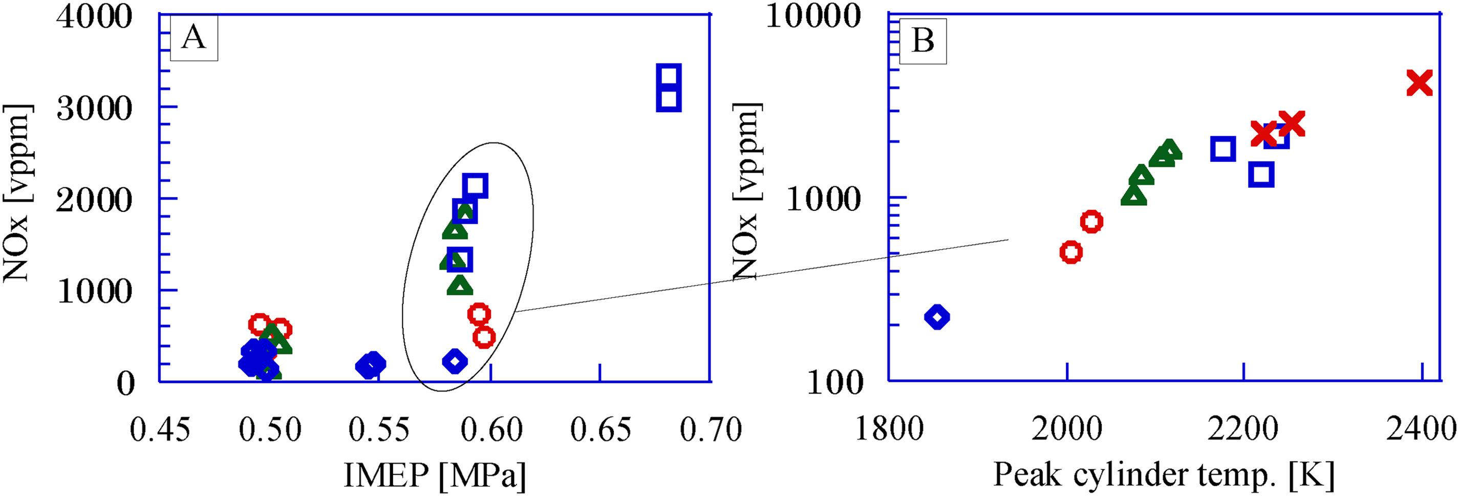
Nox in the exhaust gas. (a) NOx volume fraction vs. IMEP, (b) NOx volume fraction vs. Peak cylinder temp. □: Upgrade bio-syngas, 〇: Bio-syngas with CH4, △: Bio-syngas with H2, ◇: Bio-syngas without addition, ×: CH4(Ref.). IMEP: covariant of indicated mean effective pressure.
Figure 7 shows the CO volume fraction in the flue gas for each gaseous fuel. When the fuel is incomplete combustion, the CO ratio in the exhaust gas generally increases. The operating conditions of the GP-SIRE when measuring the CO volume fraction are the same as in Figure 7. CO in the exhaust gas of the GP-SIRE operating under this EAR is very low and almost negligible. There are no strict regulations regarding the CO ratio in the exhaust gas of power generators in stationary applications. On the other hand, the legal regulation of automobile exhaust gas is clearly stated in the “Safety Standards for the Road Transportation Vehicles” issued by the Ministry of Land, Infrastructure, Transport and Tourism (MLIT). According to Article 137 of this standard, the CO ratio in the exhaust gas from idling vehicles must not exceed 0.5%. The dotted line in Figure 7 indicates that the maximum CO volume fraction in exhaust gas is about 0.1 v%. Therefore, if the vehicle emission regulation were to be applied to engines for power generation, the CO ratio in the exhaust gas is not a problem, regardless of which gaseous fuel type is used.
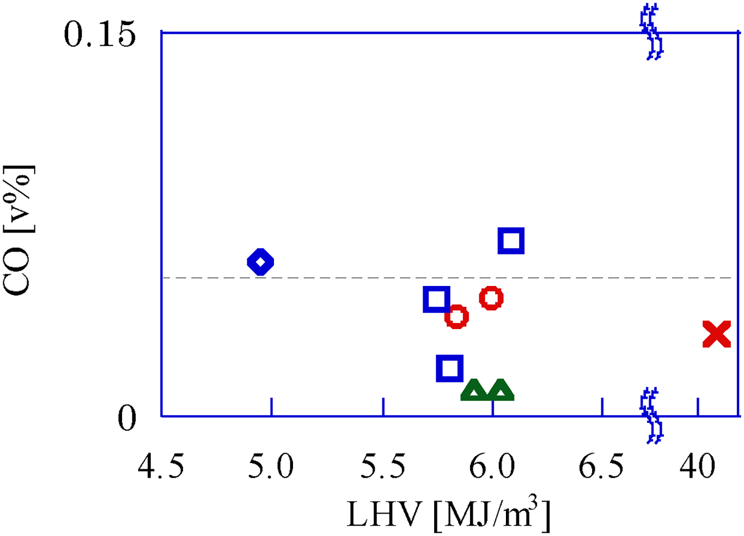
Volume fraction of CO in the exhaust gas for each gas fuel. □:Upgrade bio-syngas, 〇: Bio-syngas with CH4, △: Bio-syngas with H2, ◇: Bio-syngas without addition, ×: CH4 (Ref.).
Figure 8 shows the COV-IMEP for the GP-SIRE operating with each gaseous fuel. Compared to the CH4 operation, the COV-IMEP of the GP-SIRE operating with the bio-syngas mixture is small, despite the lean fuel conditions. This phenomenon is due to the preferential diffusion effect in Kido and Nakahara (1998), which has been reported for the combustion of fuels with high diffusion coefficients, such as H2. Kido and Nakahara (1998) also report that the preferential diffusion effect is a phenomenon in which chemical species with high diffusion coefficients preferentially enter the flame surface propagating in the cylinder, resulting in a locally fuel-rich mixture and changing the laminar combustion velocity of the mixture.
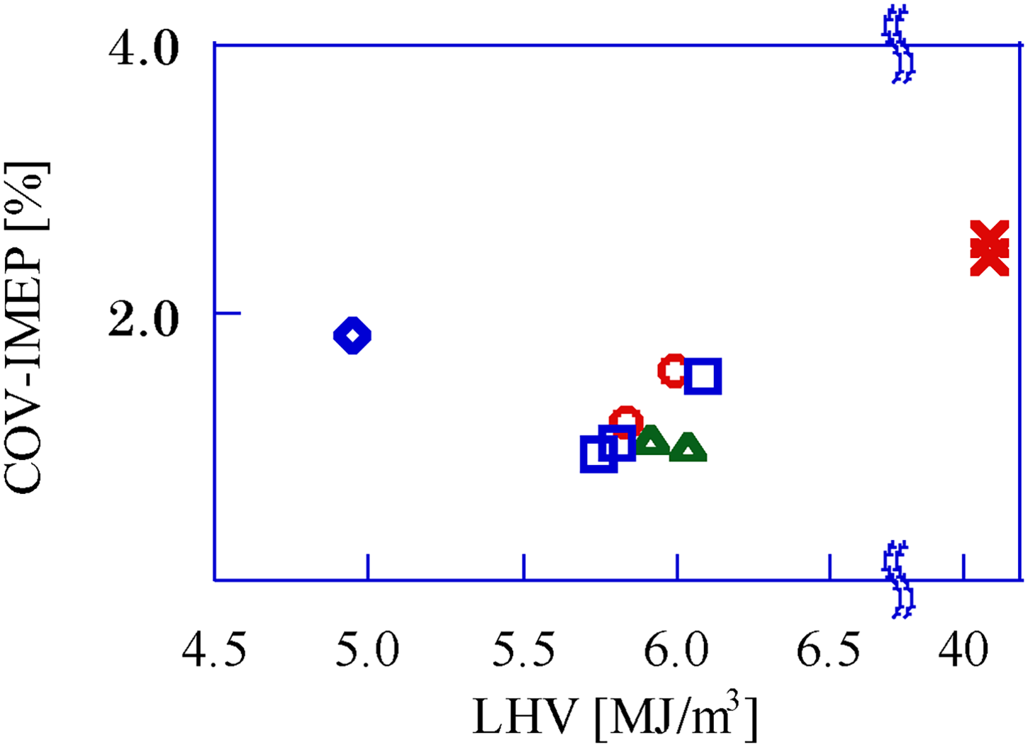
COV-IMEP for each gaseous fuel. □: Upgrade bio-syngas, 〇: Bio-syngas with CH4, △: Bio-syngas with H2, ◇: Bio-syngas without addition, ×: CH4(Ref.). COV-IMEP: covariant of indicated mean effective pressure.
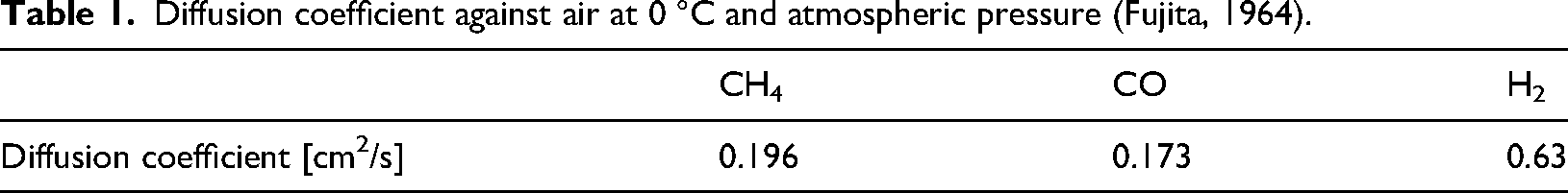
Fujita (1964) shows the diffusion coefficient of each combustible gas component in the bio-syngas against the air at 0 °C atmospheric pressure (Table 1). H2 has a higher diffusion coefficient than the other combustible gas components. Gaseous fuels that have high H2 ratio, such as the bio-syngas, can operate stably even under lean fuel operating conditions. On the other hand, Ando et al. (2005) report that the combustion instability is high in the case of the fuel-rich operating condition. This condition is also caused by the preferential diffusion effect, where the mixture enters the flame surface and becomes more fuel-rich locally than in the fuel-lean case, and the combustion is prevented.
Diffusion coefficient against air at 0 °C and atmospheric pressure (Fujita, 1964).
For high H2 ratio gaseous fuels such as the bio-syngas, a locally fuel-rich mixture at the flame surface can be avoided by the fuel-lean condition due to the preferential diffusion effect. Ando et al. (2005) report that the region of stable combustion of fuels with a high H2 ratio, such as the bio-syngas, is shifted to fuel-lean conditions. Li et al. (2018) also report that the flame becomes stable as the CO volume fraction, as a percentage of the combustible gas volume fraction, increases in the case of fuels that contain H2, CO, and N2 combusted in a lean fuel-lean condition. Due to the decrease in H2 ratio with a high diffusion coefficient, the flame surface thickness is increased. For these reasons, a general-purpose reciprocating engine operating with gaseous fuels, including the bio-syngas, combust stably even under fuel-lean operating conditions. This promotes complete combustion of the CO in the mixture, so the CO volume fraction in the exhaust gas is very small.
Conclusion
Volume fractions of NOx and CO in exhaust gas were compared for the GP-SIRE operating with the bio-syngas, the upgrade bio-syngas, the bio-syngas with H2, and the bio-syngas with CH4. The results are as follows.
The NOx volume fraction in the exhaust gas exceeded the NOx limit when the GP-SIRE was operated with any of the gaseous fuel types in the experiment. Therefore, after-treatment systems should be installed to purify the exhaust gas. The GP-SIRE contains the bio-syngas in the fuel, operates stably under fuel-lean conditions, and the volume fraction of CO in the exhaust gas is negligibly small.
Article highlights
NOx in exhaust are within the standard.
Fuel-lean conditions promote complete CO combustion.
Combustion stability of bio-syngas mixture by preferential diffusion effect of H2.
Supplemental Material
sj-pdf-1-eea-10.1177_01445987251339847 - Supplemental material for LHV effect on reducing exhaust NOx and CO from a reciprocating engine operated with bio-syngas
Supplemental material, sj-pdf-1-eea-10.1177_01445987251339847 for LHV effect on reducing exhaust NOx and CO from a reciprocating engine operated with bio-syngas by Hiroshi Enomoto and Ryo Nakagawa in Energy Exploration & Exploitation
Footnotes
Ethics approval
Not applicable.
Consent to participate
Not applicable.
Consent for publish
Not applicable.
Author contributions
HE contributed to methodology, writing—original draft, formal analysis, and data curation, validity, concretization, reviewing, and editing. RN contributed to supervision, reviewing and editing, visualization, and resources.
Funding
The authors received no financial support for the research, authorship, and/or publication of this article.
Declaration of conflicting interests
The authors declared no potential conflicts of interest with respect to the research, authorship, and/or publication of this article.
Data availability statement
The data that support the findings of this study are available from the corresponding author, upon reasonable request.
Supplemental material
Supplemental material for this article is available online.
References
Supplementary Material
Please find the following supplemental material available below.
For Open Access articles published under a Creative Commons License, all supplemental material carries the same license as the article it is associated with.
For non-Open Access articles published, all supplemental material carries a non-exclusive license, and permission requests for re-use of supplemental material or any part of supplemental material shall be sent directly to the copyright owner as specified in the copyright notice associated with the article.