
Abstract
Close-hole roof-cutting technology (CHRCT, also called “dense drilling”) has been widely applied in coal mines due to its economic and safety benefits. Inappropriate cutting parameters and support schemes can lead to dynamic pressure disturbances in self-forming roadways with thick and hard roofs. Moreover, fully characterizing the procedure and process of self-forming roadways using CHRCT in the field is difficult, resulting in unconvincing results. Therefore, this study aims to fill the gaps in theoretical knowledge and methodology. First, the dynamic pressure characteristics of the self-forming roadway using CHRCT were investigated, and the dynamic pressure types of the roadway were classified. There are three main types: roof cut off along the coal wall side of, severe deformation, and overhanging roof of a roadway after the second working face mining. The effects of different hole parameters (inclination angle, depth and spacing) on the roof cutting to form a roadway were also investigated. The optimal hole inclination, depth and spacing of 15°, 8 m, and 200 mm were determined through a series of experiments. Then, three support schemes embedded in the roadway were compared in terms of stress evolution, bolt and cable axial forces, roof displacement, and structure. Finally, this study proposes a dynamic pressure mitigation strategy through the optimization of parameters for close-hole roof-cutting and support schemes, monitoring and controlling ground pressure in roadways, and taking auxiliary measures for pressure relief. The results show that this strategy can effectively eliminate the dynamic pressure of the roadway and meet the stability requirements of the full mining cycle. This paper presents a methodology for analysing CHRCT via numerical simulation. Moreover, this approach is of great theoretical and practical importance for dynamic pressure control for self-forming roadways using CHRCT in thin coal seams with thick and hard roofs.
Keywords
Introduction
In recent years, a new technology known as the N00 coal mining method has been proposed (Wang et al., 2018). This approach enables the mining of N working faces in a mining area without preentry excavation or coal pillar retention, resulting in significant economic and safety benefits for the mine (Wang et al., 2023). The most crucial challenge in the N00 coal mining method is to keep the entry safely behind the working face (Fu et al., 2024; Yang et al., 2019).
However, one of the most problems for the double-lane layout is that the return lane, which serves both this working face and the adjacent working face, would experience serious deformation and damage due to the impact of mining in the two working faces (Kang et al., 2019; Shen et al., 2023; Zhang et al., 2020, 2023). As an important technical means of N00 coal mining, roof cutting and decompression are crucial for entry stability. At present, energy blasting (Gao et al., 2019; Shen et al., 2023; Zhang et al., 2020) and hydraulic fracturing (Xia et al., 2018) are the main focuses of research on roof cutting and decompression technology. The two techniques mentioned above have been difficult to apply in some mines due to strict blasting regulations and a lack of water. As an alternative method, roof cutting is carried out by drilling many closely spaced holes in the advance working face to precrack the entry roof (Li et al., 2023d; Ma et al., 2023; Xia et al., 2023). Therefore, the roof can be cut down under the action of an overburden load and its own weight to form a roadway for subsequent working face mining. Because no blasting is needed and this process is simple and highly adaptable, this method has become increasingly popular.
Zhou (2019) found that roof cutting can be achieved by drilling closely spaced holes through field tests. However, the deformation of the roadway is larger and the deformation time is longer than those with blasting roof cutting. Li et al. (2022) reported that the closely spaced holes increase the tensile stress concentration during roof deformation, causing weakening zone development. Li et al. (2023d) carried out systematic statistical analyses of the key parameters affecting close-hole roof cutting and proposed a method for determining the key parameters. However, research on close-hole roof-cutting processes and support technology still cannot meet the increasing demand for engineering practice because the related research is relatively limited.
Approximately one-third of the roofs of coal mines in China are thick, hard rock formations (Lu et al., 2019; Yu et al., 2022). These rock formations are untimely collapse due to their high load-bearing capacities (Xia et al., 2023). An exposed roof structure with a long span often forms, which results in strong dynamic pressure on the entry. The roof collapse is not sufficient due to the small mining height, especially for thin coal seams with thick and hard roofs. As a result, the caved gangue cannot effectively support the weight of the overburden, which may be suddenly released. On the other hand, the thick and hard roof conditions impose new requirements on close-hole roof-cutting technology (CHRCT) and support schemes for roadways. An inappropriate scheme can easily cause dynamic pressure on roadways. Therefore, there is a knowledge gap in the dynamic pressure mitigation strategy for self-forming roadways using CHRCT in thin coal seams with thick and hard roofs.
Numerical simulations on dense drilling weakening roofs and its application in roof control are getting more attention from scholars (Liu et al., 2023; Ma et al., 2023; Wang, n.d.; Xia et al., 2023). From a methodological point of view, CHRCT involves a series of roof deformations, such as sinking, collapsing and accumulating. The “continuous-discontinuous-large deformation” process is difficult to fully simulate experimentally. Thus, the reliability of these methods is reduced because of the obvious difference between the close-hole roof-cutting process in the numerical simulation and on-site practice. Moreover, small dimensions are generally studied on cutting parameters. Although they have great advantages for CHRCT, they have obvious limitations for spatiotemporal matching of CHRCT parameters and support systems for field practices.
In summary, considering the gaps in theoretical knowledge and methodology, a mitigation strategy for the dynamic pressure of self-forming roadways using CHRCT in thin coal seams with thick and hard roofs was established in this article. First, the dynamic pressure characteristics of the self-forming roadway under close-hole roof cutting were investigated, and the dynamic pressure types of the roadway were classified. Second, the effects of different parameters of close-hole roof cutting on roadway formation were analyzed. Based on the above work, the support scheme can meet the stability requirements of the entire mining cycle. Finally, dynamic pressure mitigation is possible with parameter optimization of the close-hole roof-cutting method, the monitoring and control of ground pressure in the roadway, and auxiliary measures for pressure relief. The effectiveness of the dynamic pressure mitigation strategy was verified by a case study. This article provides a methodology for the numerical simulation of the close-hole roof-cutting process and associated technology. Moreover, dynamic pressure mitigation strategies for CHRCT in thin coal seams with thick and hard roofs are highly theoretically and practically important.
Dynamic pressure types of self-forming roadways in thin coal seams with thick and hard roofs
The CHRCT is well documented in references (Li et al., 2023d; Ma et al., 2023; Xia et al., 2023). It consists of the following processes. First, a precise CHRCT is implemented to sever the connection between the gob-side roof and entry roof, allowing the two sides of the cutting crevice to move independently. Additionally, constant-resistance cable supporting technology (CRCST) is employed to ensure the stability of the short cantilever roof structure above the entry, while dynamic pressure-bearing supporting technology (DPBST) is used to withstand roof deformation under dynamic pressure. After completing the roof cutting and entry supports, the hydraulic supports for the working face are moved forward. The gob-side roof is near the entry caves, and the collapsed rock mass fills the mining space, providing support for the high-level roof and bringing the system to equilibrium (Wang et al., 2023). The collapsed gangue on the gob-side of the roadway forms an enclosed roadway for the next working face mining.
In practice, the following dynamic pressure phenomena may be encountered when using CHRCT in thin coal seams with thick and hard roofs.
Roof cut off along the coal wall side of a roadway
As the face advances, a masonry beam structure forms not only along the length of the face but also along its inclination. The key blocks of the beam near the gob-side entry are mainly supported by the entry and the caved gangue. Compared to a thicker seam, a thin seam causes less disturbance to the overlying strata due to the limited mining height. This phenomenon is especially important for coal seams with thick and hard roofs, where insufficient roof collapse can occur. Caved gangue is unable to effectively support the weight of high-level roofs. Additionally, if the CHRCT parameters are not suitable, it becomes difficult to cut the roof in a timely and effective manner. This leads to a large span of the roof. As a result, the roof will be tilted or even cut off along the coal wall side of the entry by these weights (see Figure 1(a)).
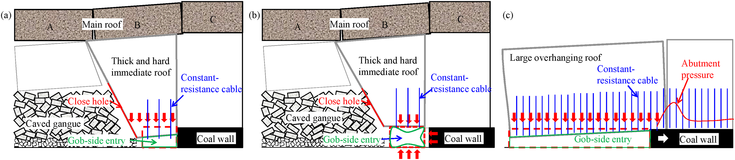
Dynamic pressure types of the self-forming roadway in a thin coal seam with a thick and hard roof: (a) roof cut off along the coal wall side, (b) severe deformation, and (c) overhanging roof behind the working face.
Severe deformation of a roadway
With working face mining, the gob-side entry experiences excavation unloading, the first working face mining-induced abutment pressure, a first periodic weighting, the second working face mining-induced abutment pressure, a second periodic weighting and other mining disturbances. Therefore, severe roadway deformation, such as rock weakening, roof subsidence, and floor heave, frequently occurs under the action of multiple mining disturbances (Li et al., 2023a, 2023b) (see Figure 1(b)). On-site ground pressure monitoring results also reveal that the area affected by dynamic pressure is the most notable (Li et al., 2023c). Moreover, the scope of the influencing zone increased significantly during the second mining disturbance.
Overhanging roof of a roadway after the second working face mining
To ensure gob-side entry safety based on CHRCT, the dynamic pressure described in Roof cut off along the coal wall side of a roadway and Severe deformation of a roadway sections must be avoided. These models provide a lower limit of support strength for such conditions. However, the entry behind the working face forms a simply supported beam after the second face mining if the support strength is too high.
The abutment pressure in front of the working face increases with increasing overhanging length. As a result, the influence area of the roadway increases, and spalling and floor heave occur. An excessive overhanging length of the roof behind the working face provides the possibility of a sudden collapse (see Figure 1(c)). Therefore, it is also necessary to avoid the occurrence of large overhanging roofs during second working face mining.
Experimental program and set-up
Experimental scheme
The distinct element method is suitable for the simulation of systematic motion and nonlinear large deformations of multiple blocks, and it has a significant advantage in simulating overburden movement as well as entry stability.
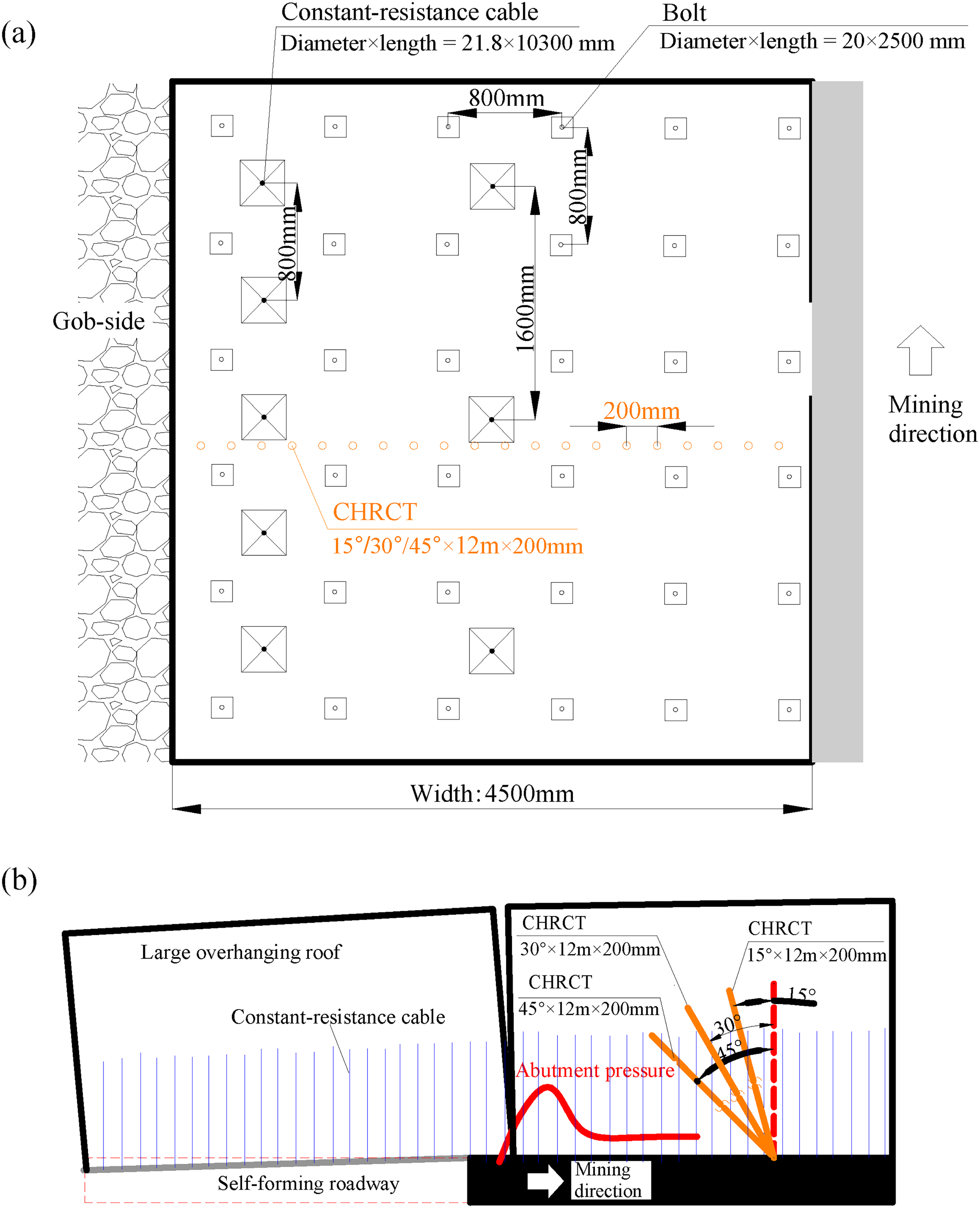
To quantitatively characterize the stress and deformation of the roadway during the mining process, the stress and displacement are measured at 10 m intervals along the direction of the roadway strike. Moreover, measurement lines are placed on both the gob-side and coal-wall roofs to capture the difference in roof movement. The experimental program is shown in Figure 2.
Experimental scheme.
Numerical modeling
The numerical model was established according to the lithological characteristics of the 203 working faces in the Ruineng Mine (Table 1). The thickness of the coal seam is between 1.69 and 2.80 m, with an average thickness of 2.20 m. The width and height of the No. 203 haulage way are 4.5 and 2.6 m, respectively, with a general east‒west arrangement. The maximum depth of the roadway is 315 m. There were 50 m boundary coal pillars on each side of the model. Furthermore, simulating complete overlaying strata in the vertical direction is challenging due to the limitations of model arithmetic. Therefore, the numerical model dimensions were set to 300 m in length, 504 m in width, and 180 m in height. Unmodelled overburden was achieved by applying equivalent loads at the top of the model. Displacement constraints were applied to the remaining five faces to limit model movement (see Figure 3(a)).
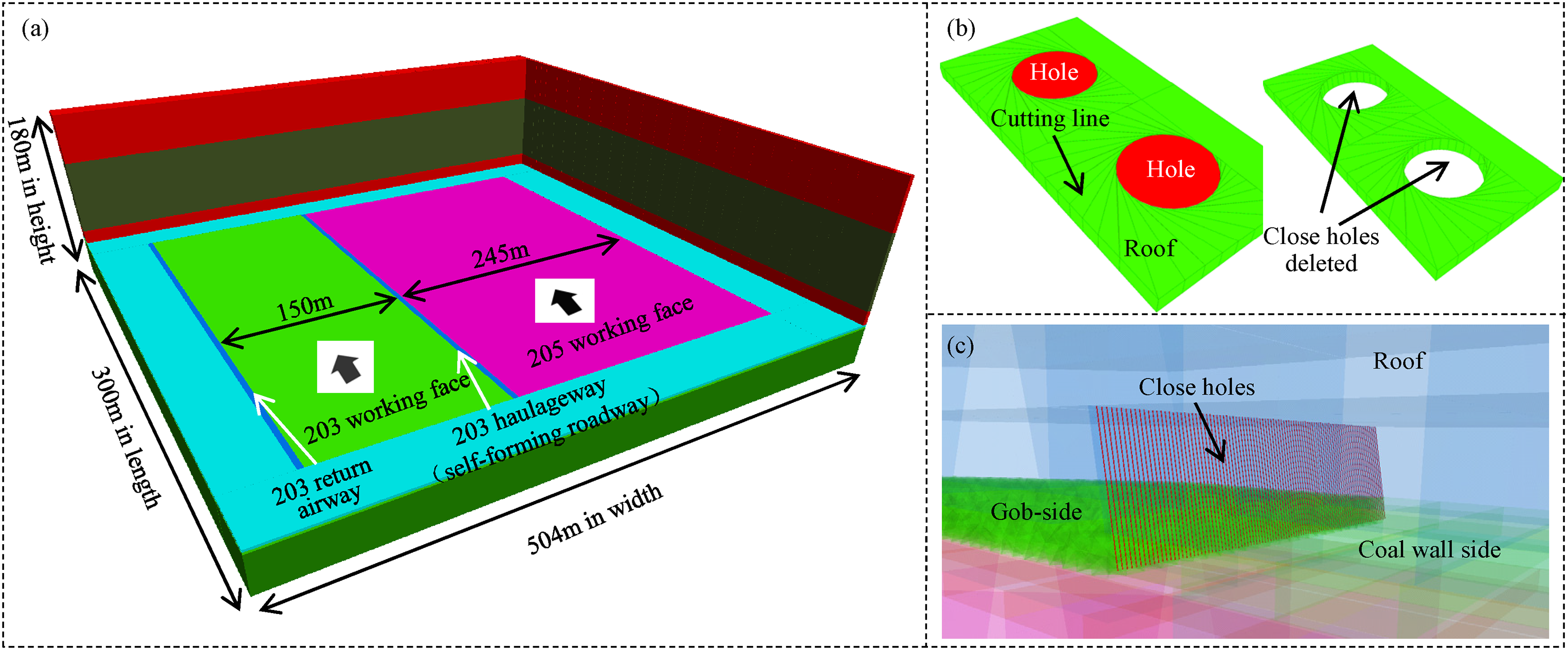
The numerical model: (a) full model, (b) hole generation and excavation schematic, and (c) partially enlarged detail of the close hole along the strike direction of the roadway.
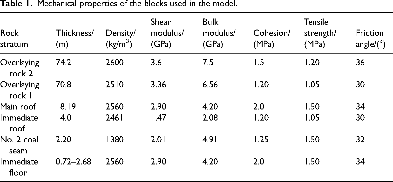
Mechanical properties of the blocks used in the model.
To better capture the collapsing and filling effect of the overlying rock after coal seam excavation, the bonded block model (BBM) was applied to the immediate roof within the No. 203 working face. The BBM is a modeling technique used by 3DEC to analyze rock fracture propagation and fragmentation (Garza-Cruz and Pierce, 2014). It consists of a series of very small tetrahedrons. As the size of these blocks is small enough, it is assumed that the blocks are elastic in nature. The contacts between blocks exhibit an elastic‒plastic state, and damage occurs along these contacts. The BBM specializes in analysing rockfall fragmentation in mining engineering. This approach has significant advantages in simulating the real situation of rock brittle.
Holes with circular cross sections were drilled using a high-strength drill bit in the field. Cylindrical holes were therefore used in the modeling for simplification because the software cannot directly generate the actual drill hole shapes. The specific modeling methods for the closely spaced holes were as follows: (i) The modeling scope was limited by hiding rock larger than the radius of one hole and above and below its height. (ii) Cutting points and orientations were selected on a circle centered around the coordinates of the center of the hole (x0, y0), with r0 as the radius to cut the block using the FISH language. The cutting points and orientations were determined according to a FISH function (see Figure 3(b)). (iii) Steps 2 and 3 were repeated to generate all the holes along the direction of the roadway strike; see Figure 3(c). The holes inside the roadway roof were excavated (deleted) at a later stage of the calculation process to achieve roof precracking.
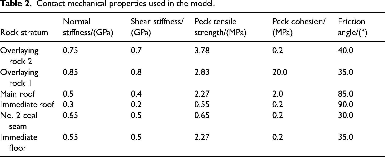
Uniaxial compression numerical models for various rocks were established, and the microscopic parameters were continuously adjusted to achieve a continuous approximation of the macroscopic uniaxial compressive strength (UCS) and elastic modulus of the rock mass. The calibrated microscopic parameters were assigned as in Tables 1 and 2. The Coulomb slip model was used for the blocks. The Mohr‒Coulomb joint model was used to assign different properties to each subcontact.
Contact mechanical properties used in the model.
Validation
The purpose of this section is to illustrate the reasonability of the numerical simulations and to provide a reliable basis for the following analyses.
Roof precracking ahead of the working face
Figure 4 shows the stress distribution characteristics of the working face advancing 100 m in the advanced influence area. The maximum vertical stresses around the holes are 17.13, 36.08, 13.02, 14.14, and 13.85 MPa as the face advances from 10 to 50 m. In terms of stress type, all the stresses are tensile stresses, indicating that the surrounding rock around the holes is subject to tensile effects from mining activities. In terms of stress concentration, the stress around the holes is the highest, indicating that the stress concentration around the holes is the most significant. This confirms the precracking effect on the roof (Liang et al., 2021; Zhang et al., 2019). In terms of the stress gradient, the stress around the holes increases and then decreases as the distance increases along the strike direction of the roadway (Xia et al., 2023). The advanced abutment stress of the working face shows zoning characteristics, namely, a stress elevation zone, a stress reduction zone and a stress stabilization zone. The zoning characteristics along the strike of a working face are in good agreement with previous studies.
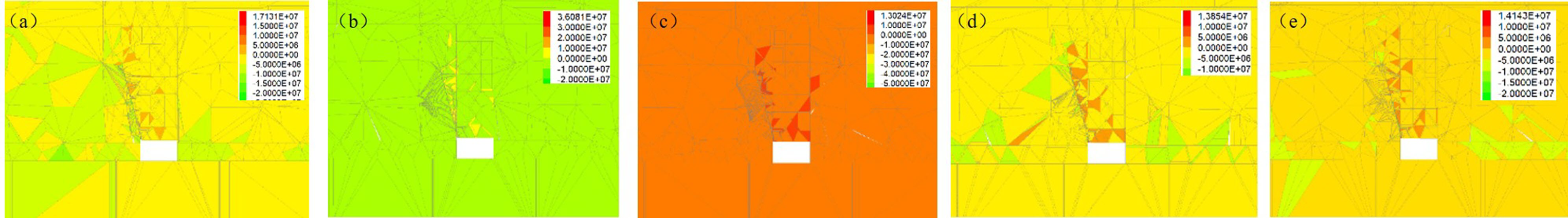
Stress distribution as the working face advances 100 m in sections from 10 to 50 m ahead. (a) 10, (b) 20, (c) 30, (d) 40, and (d) 50 m.
Roof-cutting and self-forming a roadway
Figure 5 shows the process and procedure for creating a roadway using CHRCT in the numerical simulation. As shown in the figure, some of the rock around the hole slipped, and the roof of the roadway on the gob side dropped slightly at step 38947 (see Figure 5(a)). The immediate roof collapsed further at step 87788, and roof subsidence occurred along the cutting line under the effect of precracking ahead of the working face (see Figure 5(b)). The low immediate roof was essentially cut off completely at step 153339 and was piled regularly along the roadway. However, an articulated structure was formed between the high immediate roof and the layers above the cutting level (see Figure 5(c)) and Figure 5(d) shows the final result of creating a roadway using CHRCT. As shown in the figure, the low immediate roof collapsed and piled up to form the roadway gang, and the high immediate roof and main roof formed a short-wall beam structure. The effect of roadway formation is good. The numerical calculation results can fully characterize the effect of precracking and the effect of roof cutting and self-forming a roadway, which provides a reliable basis for the analysis below (Liu et al., 2024; Wang et al., 2023).
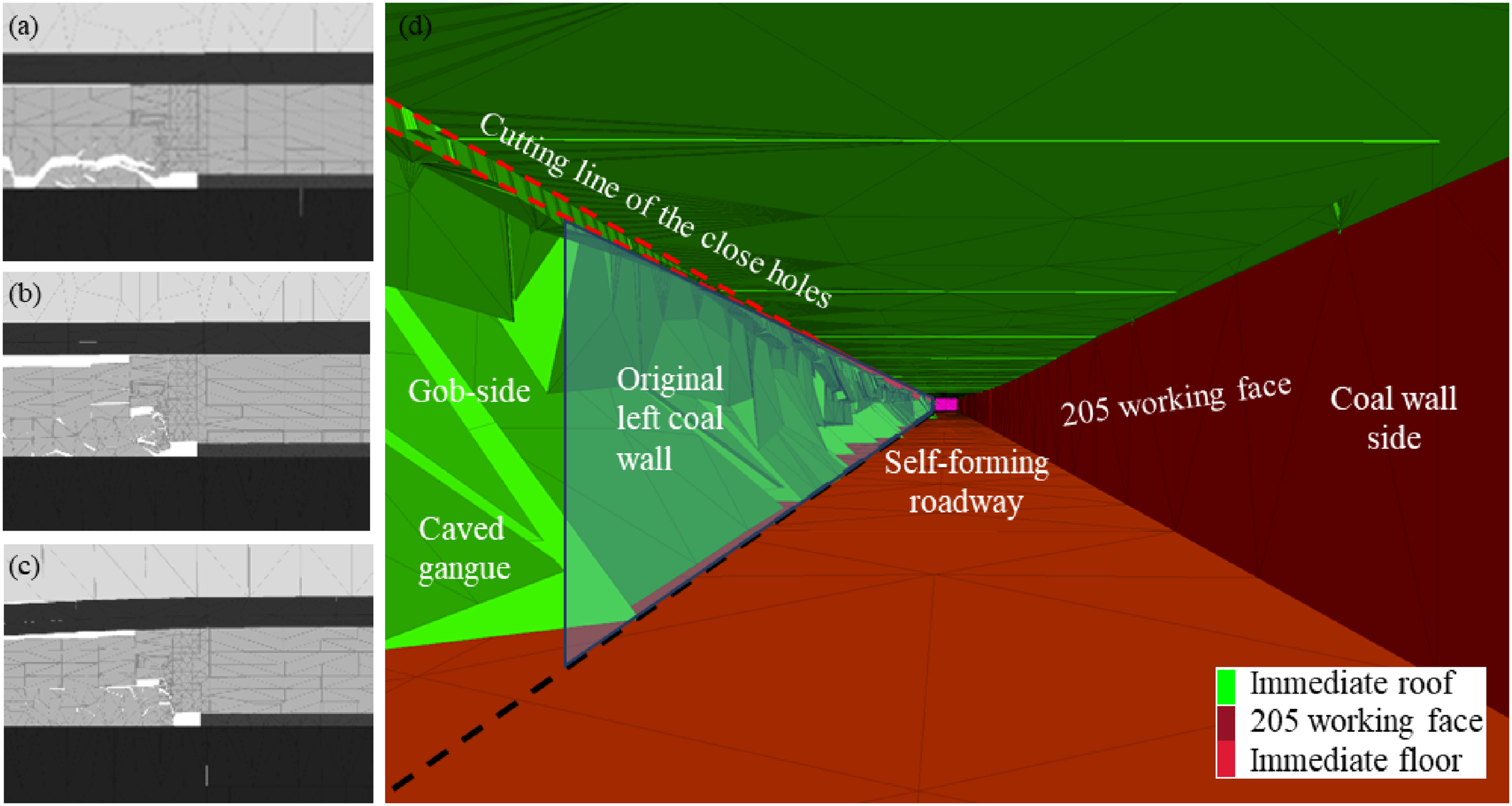
The process and procedure for creating a roadway using CHRCT in the numerical simulation: (a) step 38947, (b) step 87788, and (c) step 153339.
Optimizations of close-hole roof-cutting parameters and support scheme
The cutting parameters and support scheme are key for ensuring roadway stability based on CHRCT in thin coal seams with thick and hard roofs. Therefore, roadway stability should be maintained throughout the entire cycle, and large overhanging roof hazards should be removed after the second working face is mined out. The first step was to optimize the close-hole roof-cutting parameters to ensure a good gob-side entry. Three support schemes embedded in the gob-side entry were then compared to ensure a well-supported roadway. The scheme is shown in Figure 2.
Close-hole roof-cutting parameter optimization
Inclination of the closely spaced holes
The roof displacement and rock structure of roadways were measured at inclination angles of 0°, 5°, 10°, and 15° (see Figure 6). The effect changes as the inclination increases from 0° to 15°. When the hole inclination angle is 0°, the roof is strongly constrained by the rock layer in the horizontal direction in the mined area, and the friction action is greater during the process of slewing and sinking. This leads to a delay in roof collapse in the mined area. By increasing the inclination angle of the closely spaced holes, the horizontal constraint of the roof in the mined area was weakened to some extent, resulting in a smoother roof collapse. The maximum vertical displacement of the gob-side roof increased from 0.6 to 1.8 m when the hole inclination angle increased from 0° to 15°. The maximum horizontal displacement of the roof adjacent to the roadway increased from 0.02 m at 0° to 0.25 m at 15°, which is a small displacement and requires less lateral support resistance to the roadway. Overall, it is better to cut the roof to form a roadway when the hole inclination angle is 15°.
Roof displacement and rock structure of roadways with different hole inclinations: (a) 0°, (b) 5°, (c) 10°, and (d) 15°.
Hole depth
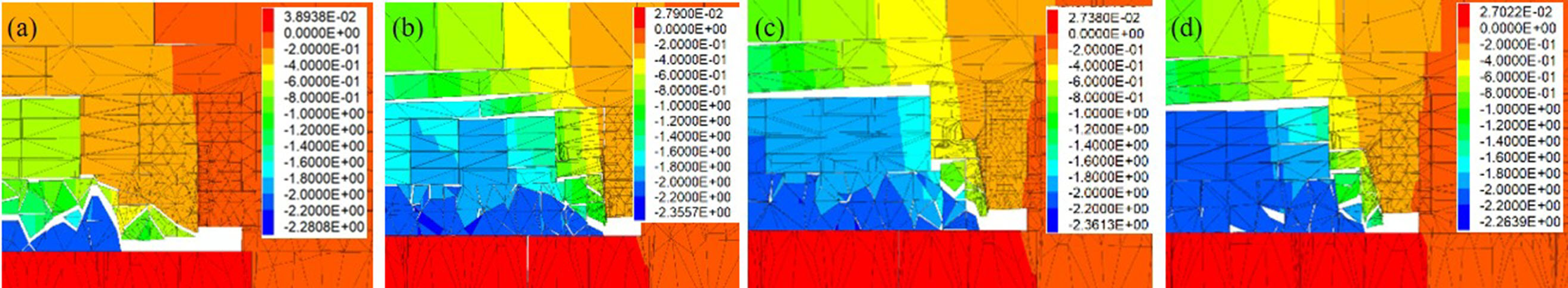
The roof displacement and rock structure of roadways with different hole depths are shown in Figure 7. At 6 and 7 m, the upper part of the immediate roof is overhanging in the mined area. The roof can be cut off, and there is little difference at hole depths of 8 and 9 m. As the hole depth was increased from 6 to 9 m, the vertical displacement of the roof in the mined area was 0.4, 0.8, 1.8, 1.9 m and the horizontal displacement was 0.05, 0.07, 0.25, 0.29 m. The construction difficulty increases as the hole depth increases. Moreover, the drilling accuracy decreases. Therefore, the optimal hole depth was determined to be 8 m.
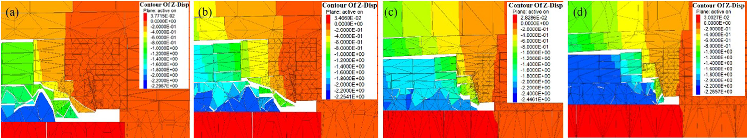
Roof displacement and rock structure of roadways with different hole depths: (a) 6, (b) 7, (c) 8, and (d) 9 m.
Distance between two adjacent holes
Figure 8 shows the roof displacement and rock structure of roadways when the spacing of dense holes is 150, 200, and 300 mm. The roof can be cut off when the hole spacing is 150 or 200 mm. It is difficult to penetrate the fissure between the holes when the hole spacing is 300 mm. As a result, the immediate roof cannot be cut off. The fractured zone around the holes superposes if the hole spacing is small enough. An almost continuous fracture zone is created by mining activity. As a result, the roof can be cut off and collapse along the fracture zone. The maximum vertical displacement of the roof in the mined area was 2.42 and 2.31 m and the maximum horizontal displacement was 0.28 and 0.35 m when the hole spacing was 150 and 200 mm, respectively. The collapsed gangue accumulation next to the roadway was more orderly, and the lateral support resistance requirement was lower. Moreover, a significant increase in labor intensity by reducing the hole spacing was taken into account. The optimal distance between two adjacent boreholes was therefore 200 mm.
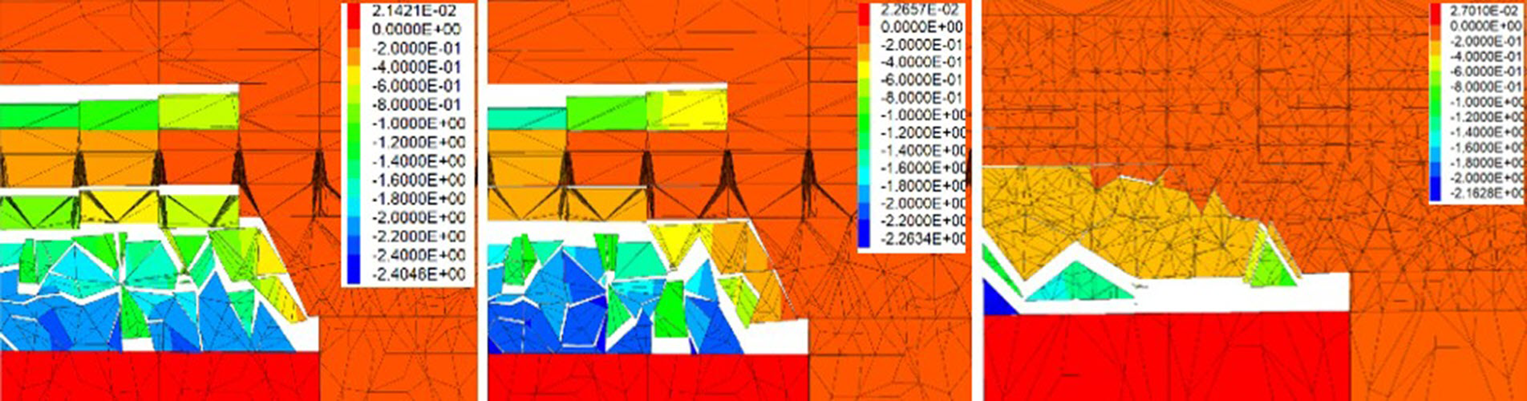
Roof displacement and rock structure of roadways with different hole spacings: (a) 150, (b) 200, and (c) 300 mm.
Support scheme for the roadway
The original support for the No. 203 haulage roadway was as follows. Bolt-net-cable combination support was adopted. The diameter and length of the roof bolts were 20 and 2500 mm, respectively, with spacings of 800 and 800 mm, the diameter and length of the roof rebars on the gob-side were 21.8 and 8300 mm, and the diameter and length of the roof bolts in the center and on the coal-wall side were 17.8 and 8300 mm, respectively, with spacings of 1600 and 1600 mm. A constant-resistance cable with a diameter and length of 21.8 and 8300 mm, respectively, is used to reinforce the support, which is arranged perpendicular to the roof. There are two rows in total; one row is placed 650 mm from the gob-side with a row spacing of 800 mm, and 1 row is placed in the center of the roadway with a row spacing of 1600 mm. Fiber-reinforced polymer bolts with diameters and lengths of 20 and 2200 mm were used on the gob-side and coal-wall side, respectively, with interrow spacings of 1100 and 1200 mm.
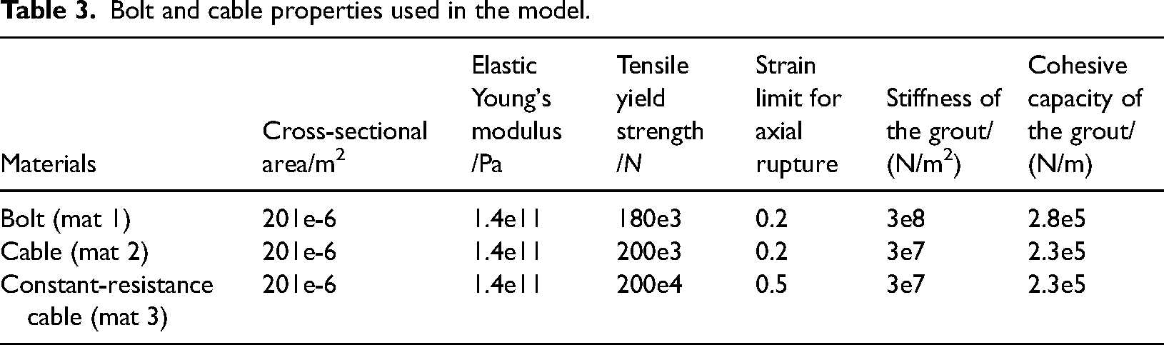
The original support design was used as a benchmark for the comparative study. Two optimized support schemes were designed by varying the parameters (length, row spacing, and number) of the constant-resistance cables. A total of three support schemes were applied to the No. 203 haulageway, and their responses were compared. The properties of the bolts and cables are given in Table 3.
Original support. See Close-hole roof-cutting parameter optimization section for details. Reinforcement support Ⅰ. Two reinforced constant-resistance cables with diameters and lengths of 21.8 and 8300 mm were changed to diameters and lengths of 21.8 and 10300 mm, respectively. The other steps are the same as those used for the original support. Reinforcement support Ⅱ. A constant-resistance cable with a diameter and length of 21.8 and 10300 mm was added to the center of two constant-resistance cables with diameters and lengths of 21.8 and 8300 mm. The other steps were the same as those used for the original support.
Bolt and cable properties used in the model.
Stress evolution of the roadway
Measurement points were selected every 40 m along the strike direction of the roadway to record the stress evolution of the roadway (see Figure 9). The roofs of the roadways with the original support and reinforcement support I and II schemes all had stress concentrations, and the maximum compressive stresses were −1.88, −1.82, and −1.44 MPa, located at 130, 10, and 90 m, respectively, of the roadway during mining of the first working face (No. 203 working face). Compared with that of the original support scheme, the roof stresses of the reinforcement support I and II schemes increased by 3.19% and 23.40%, respectively. The stresses in the roadway in the three schemes were −2.22, −2.44, and −1.62 MPa when the second working face was mined (No. 205 working face). Compared with those of the original support, the stresses in the roof with the reinforcement support I and II schemes increased by −9.91% and 27.03%, respectively.
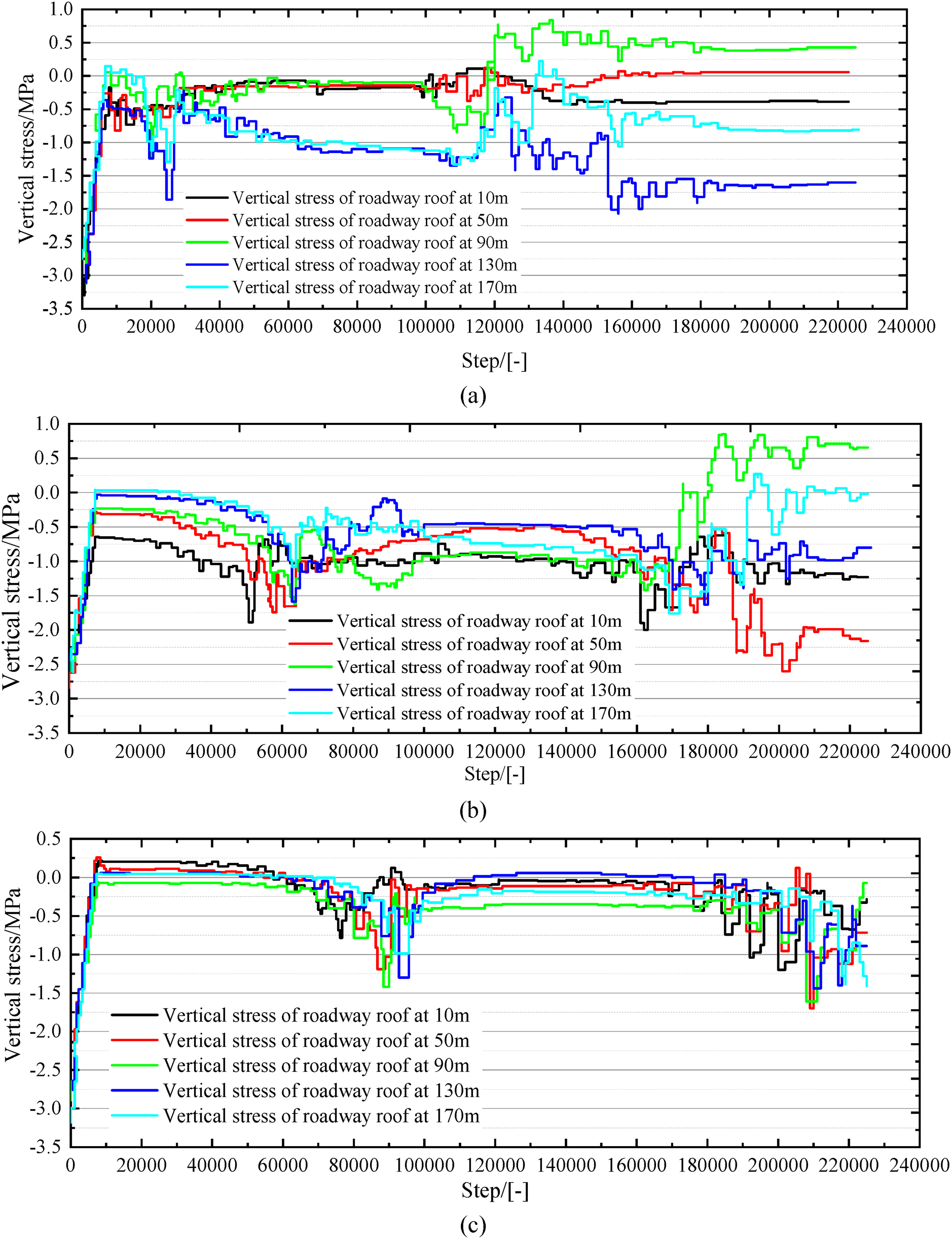
Stress evolutions of the roadway under different support schemes. (a) Original support, (b) reinforcement support I, and (c) reinforcement support II.
The stresses of the entry behind the working face were essentially unchanged after the secondary mining activities with the original support and the reinforcement support I schemes, indicating that the roadway movement had stabilized. Conversely, the stress variations were greater with the reinforcement support II scheme than with the reinforcement support II scheme, suggesting more violent movements in the entry behind the working face. It is speculated that this may be due to the presence of a large area of overhanging roof. The reinforcement support II scheme can improve the stress condition of the surrounding rock of the roadway to a certain extent. However, at the end of the secondary excavation, the movement of the strata behind the working face takes a long time in this scheme.
Axial forces and failure state of the bolts and cables
To avoid boundary effects in the region of interest, the axial force of 50 m of the bolt (cables) in the center of the model was compared under different support schemes. The results are shown in Figure 10. The maximum axial force of the cables was 105.8 kN during the first working face mining (No. 203 working face) with the original support scheme. The maximum axial forces of the bolts (cables) with the original support and reinforcement support I and II schemes were 176.5, 913.7, and 1890.6 kN, respectively, in the secondary working face mining (No. 205 working face). Compared with the mining of the first working face, the increase in the axial force of the bolts (cables) under the influence of secondary mining with the original support and reinforcement support I and II schemes are 66.82%, 763.04%, and 1686.95%. Second, compared to the original support scheme, the increase in the bolt (cable) force during the second face mining was 417.68% and 971.16% with the reinforcement support I and II schemes. The axial force of the cables increased after adopting the reinforcement support I and II schemes. This indicates an increase in the load-bearing capacity of the anchored solid consisting of the bolts (cables) together with the roof.
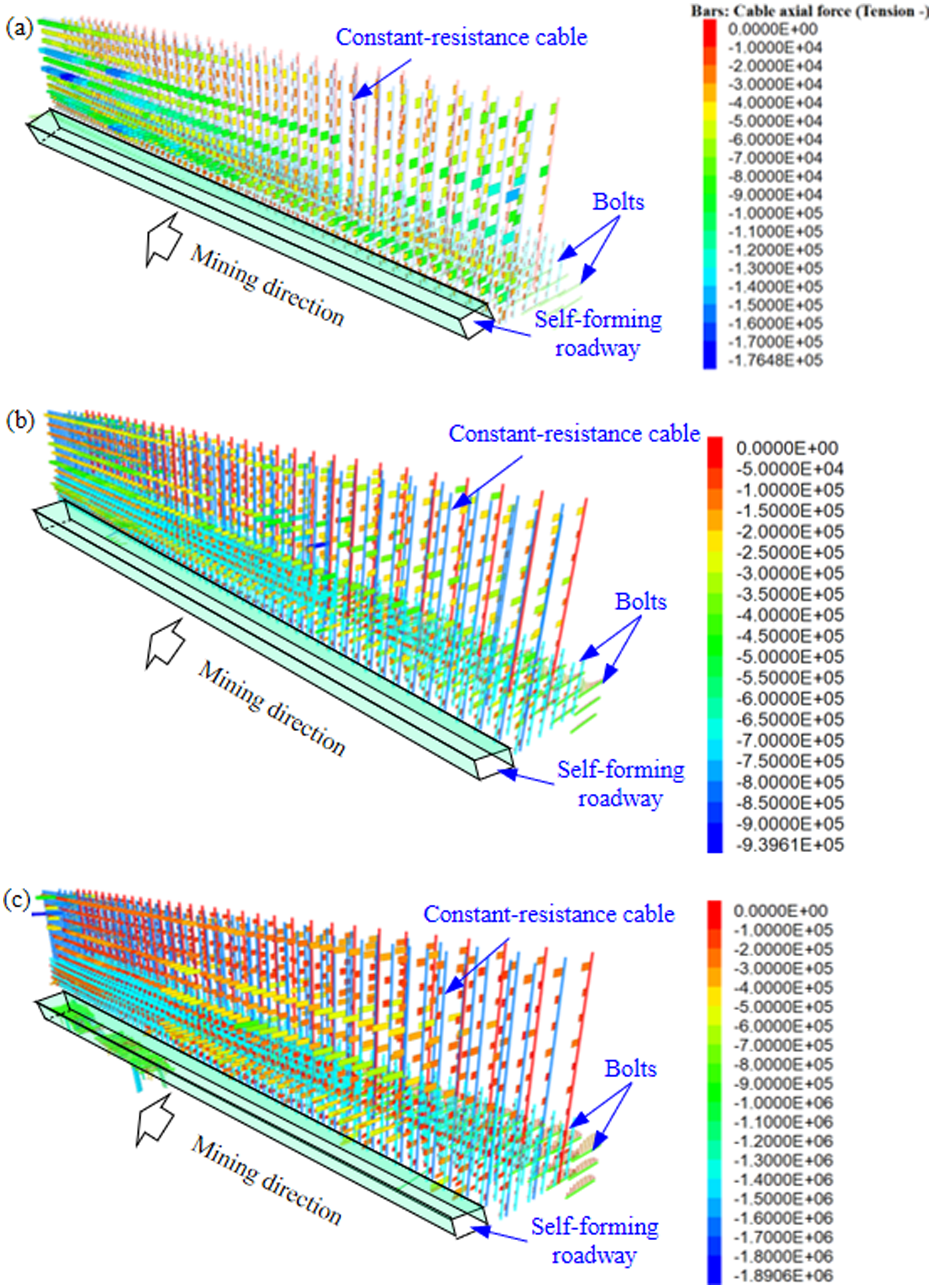
Axial forces of the bolts and cables under the different support schemes. (a) Original Support, (b) reinforcement support I, and (c) reinforcement support II.
Roof movement and roadway structure
Numerical simulation is able to analyze the stability of roadways during the full mining cycle using the CHRCT due to the advantages of good visualization options and a lot of monitoring data. Figure 13 shows the roof movement and structure of the roadway under the different support schemes. The general trend of roadway displacement was increasing. This means that the perimeter rock displacement of the roadway increases with time when the roadway was stabilized, during the mining of both the first and second faces. The maximum displacement of the roadway roof with the original support scheme was 0.344 m when mining the first working face (working face No. 203). There was no evidence of roof subsidence or floor heavening. The immediate roof collapse in the mined area was sufficient. The overall bending and sinking of the main roof resulted in the formation of an articulated structure, which was not completely broken at the boundary of the mined area (see Figure 11(a)). The maximum displacements of the roof with the original support and reinforcement support I and II schemes were 0.46, 0.42, and 0.32 m, respectively, during the secondary working face mining, as shown in Figure 11(a)–(c). When roof subsidence increased but roof collapse did not occur, the original support scheme was not suitable. Therefore, neither the main roof nor its overburden in the mined area could be supported. The length of the main roof overhang was greater after the reinforcement support I scheme was adopted, although the immediate roof was cut off. The immediate and main roof collapsed completely; therefore, there was no overhanging structure after the adoption of reinforcement support II. The maximum displacements of the entry behind the working face with the original support and reinforcement support I and II schemes were 2.12 , 2.17, and 1.85 m after secondary working face mining, respectively. The long duration and small displacement of the roadway were observed with reinforcement support II. The lag of the entry subsidence was also confirmed, and a large overhanging roof easily formed.
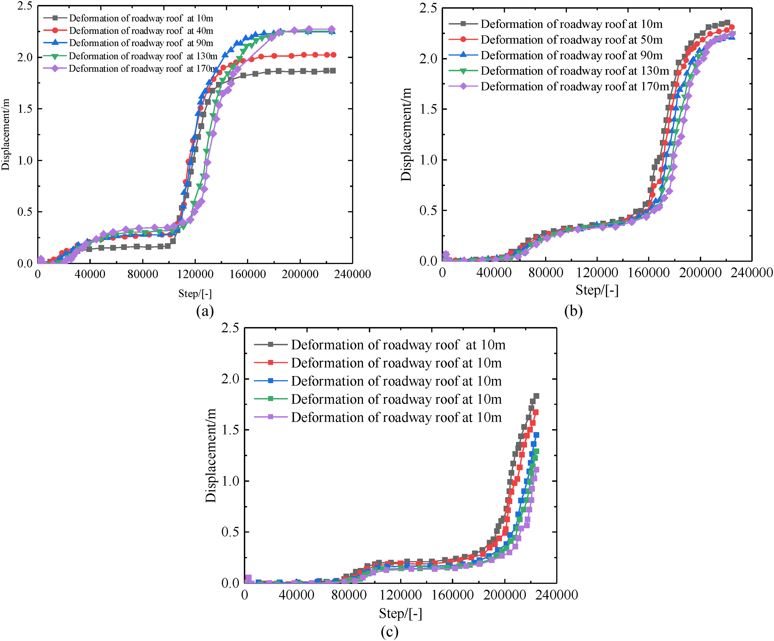
Roof movement and structure of the roadway under different support schemes. (a) Original support, (b) reinforcement support I, and (c) reinforcement support II.
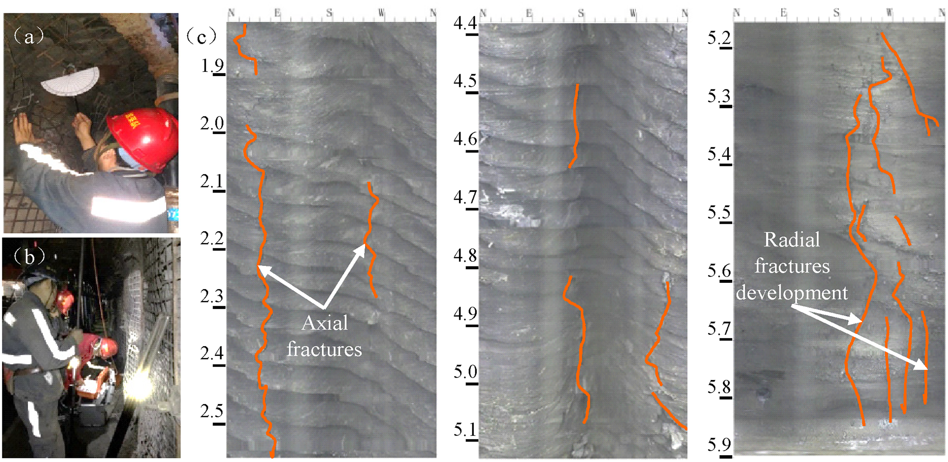
The rock integrity of the roadway using CHRCT: (a) hole inclination measurement, (b) borehole observation in the field, (c) precracking effects.
A reasonable support strength of the roadway needs to be reached by balancing the stability around the full service of the roadway and avoiding the long overhanging roof of the entry behind the working face based on CHRCT. Reinforcement support I can effectively avoid the above shortcomings through analysis.
Case study
The thickness of the coal seam in the No. 203 working face of the Ruineng coal mine is between 1.69 and 2.80 m, with an average thickness of 2.20 m. The width and height of the No. 203 haulage way are 4.5 and 2.6 m, respectively, with a general east‒west arrangement. The maximum depth of the roadway is 315 m. The thickness of the immediate roof of the roadway is 14.0 m, UCS is 35.89 MPa, and the UCS of the main roof is 59.13 MPa. The roof is typically hard and thick.
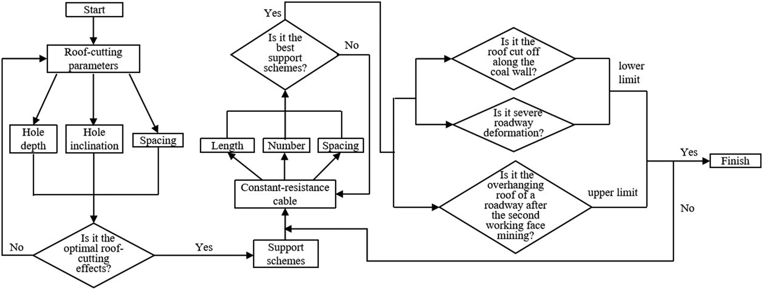
Optimization of the CHRCT and reinforcement support scheme
Based on Validation section, reasonable cutting parameters and support schemes for self-forming roadways were determined using CHRCT, as shown in Figure 12. Specifically, reinforcement support was applied on the basis of the original support scheme of the roadway by changing the constant resistance cable with a diameter and length of 21.8 and 8300 mm to one with a diameter and length of 21.8 and 10,300 mm, respectively, and the row spacing was 1600 m. At the same time, a reinforced cable with a diameter and length of 17.8 and 4300 mm was installed in the center of the coal wall side, and the row spacing was 1200 m.
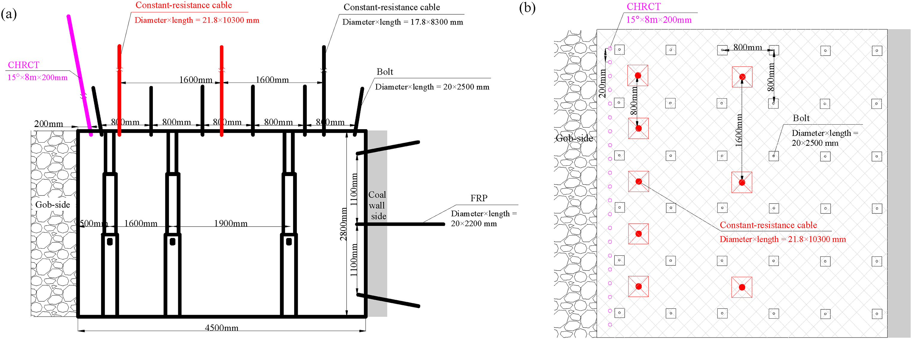
Reinforcement support of the roadway: (a) front view, (b) vertical view.
Monitoring and control of ground pressure in the self-forming roadway
To test the effect of close-hole roof cutting at the Ruineng Coal Mine, the rock integrity of the roadway was investigated (see Figure 13(a) and (b)). A borehole 50 m ahead of the working face was selected to observe the fracture before and after mining the face. The detection depth is limited to a maximum of 5.9 m due to the instrument. The results are shown in Figure 13(c), which reveals that the fractures around the hole first expand axially and subsequently form a fracture zone between adjacent holes. As a result, these cracks continue to develop in a radial direction until crack penetration occurs between adjacent holes. This shows that the hole will cut the roof well if the roof collapses in time with the advance of the face in the mined area.
Auxiliary measures for dynamic pressure relief
If the roof of the entry behind the working face forms a simply supported beam structure on both sides after mining the second working face, the roof slowly sinks. The abutment pressure in front of the working face increases with increasing overhanging length. As a result, the influence area of the roadway maybe increases, and spalling and floor heave occur. To avoid excessive roof overhang, precracking holes were drilled in advance in the area of the periodic weighting. The direction of the holes was along the width of the roadway, and the hole depth exceeded the length of the constant-resistance cable (see Figure 14).
Precracking holes along the width of the roadway during the second working face mining: (a) front view, (b) vertical view.
The displacement and roof separation of the self-forming roadway using CHRCT were monitored in the Ruineng Coal Mine. One station was arranged every 20 to 50 m, and the monitoring positions were arranged in the same section as much as possible. The stability and support quality of the self-forming roadway were analyzed, and the close-hole roof-cutting parameters and support scheme were adjusted according to the results.
Discussion and conclusions
Discussion
CHRCT is carried out by drilling many holes in advance in the working face to precrack the entry roof. Therefore, the roof can be cut down under the action of the overburden load and its own weight to form a roadway for subsequent working face mining. This technology is widely used because it does not require blasting and can improve coal recovery. In recent years, many studies on CHRCT have been carried out by scholars. However, research on roof-cutting parameters and support schemes has not yet been able to address coal seams under different geological and mining conditions.
Particularly, in the case of a self-forming roadway constructed using CHRCT in a thin coal seam with a thick and hard roof, on the one hand, the mining disturbance is weak, and the roof collapses insufficiently to support the overlying rock due to the low mining height. On the other hand, the high thickness and hardness of the roof can easily induce dynamic pressure in the roadway. Therefore, there is a knowledge gap in roadway dynamic pressure mitigation strategies using CHRCT for thin coal seams with thick and hard roofs.
Moreover, the process and procedure of CHRCT require further research. The BBM has a significant advantage in simulating the actual phenomenon of opening, sinking, and cracking of the rock in a quarry/roadway after damage has occurred. For this purpose, the BBM is used to simulate the collapse and filling of the roof after excavation. It is also important to have a process that matches the roof cutting on-site. Specifically, the intact rock mass is cut into segments to create equivalent dense holes using the built-in language. The dense holes are then excavated (deleted) in a subsequent calculation to achieve roof precracking. In this way, roadway stability can be analysed over a full mining cycle using CHRCT, exploiting the corresponding good visualization options and large amounts of monitoring data. This is what makes this article innovative in terms of the methodology used. The dynamic pressure characteristics of the self-forming roadway using CHRCT were investigated, and the dynamic pressure types of the roadway were classified. There are three main roof types: roof cut off along the coal wall side of a roadway, severe deformation of a roadway, and overhanging roof of a roadway after the second working face mining. Second, the reliability of the research methodology was confirmed by both the effect of precracking and the effect of close-hole roof cutting. The effects of different hole parameters (inclination angle, depth, and spacing) on the roof cutting to form a roadway were also investigated. Based on the optimal design of close-hole roof cutting, the mechanical responses of the roadway (stress evolution, bolt and cable axial forces, roof displacement, and structure) to different support schemes at each mining stage were compared. Finally, dynamic pressure mitigation followed the parameter optimization for close-hole roof cutting, monitoring and control of ground pressure in the roadway, and auxiliary measures for pressure relief were proposed.
Conclusions
As the inclination of the hole increased, the horizontal constraint on the roof weakened, allowing the roof to collapse in time. As the hole depth increased from 6 to 9 m, the vertical displacements of the roof on the gob side were 0.4, 0.8, 1.8, and 1.9 m, and the horizontal displacements were 0.05, 0.07, 0.25, and 0.29 m, respectively. Hole depths of 8 and 9 m were more effective than the other hole depths investigated, and the lateral resistance of the caved gangue was also low. When the distances between two adjacent holes were 150 and 200 mm, the vertical displacements of the roof were 2.42 and 2.31 m, respectively, and the maximum horizontal displacements were 0.28 and 0.35 m, respectively. With more optimal parameters, the collapsed roof was stacked in the gob in a more orderly manner, and the lateral resistance to the gob side of the roadway was also reduced.
Compared to that of original support, the roof stress increased by −9.91% and 27.03% during the second working face mining with reinforcement support I and II schemes, respectively. The stresses in the entry behind the working face were essentially unchanged after the secondary mining activities with the original support and the reinforcement support I schemes, indicating that the roadway movement had stabilized. Conversely, the stress variations are greater for reinforcement support II, suggesting that reinforcement support II mitigates rock stress to some extent, whereas the high stress caused by overhanging roofs does not. Compared with that with original support, the axial force on the bolts (cables) with reinforcement support I and II increased by 417.68% and 971.16% during the mining of the second working face. This shows that the load-bearing capacity of the anchored solid consisting of bolts (cables) and roadway roof significantly improved. The maximum displacements of the entry behind the working face with the original support and reinforcement support I and II schemes were 2.12, 2.17, and 1.85 m, respectively, after the second working face mining. The lag of the entry subsidence was also confirmed with reinforcement support II, and a large overhanging roof was formed.
The effectiveness of the dynamic pressure mitigation strategy for CHRCT in thin coal seams with thick and hard roofs was verified. This strategy ensures that the roadway meets the stability requirements during the entire mining cycle in practice and effectively eliminates the dynamic pressure hazard of the roadway.
Footnotes
Acknowledgments
The authors thank the anonymous reviewers for their comments and suggestions to improve the manuscript.
Author contributions
Conceptualization: Panshi Xie; methodology: Bosheng Hu; software: Bosheng Hu; investigation: Hao Zhang; data curation: Bosheng Hu; writing—original draft preparation: Bosheng Hu; writing—review and editing: Bosheng Hu; visualization: Bosheng Hu; supervision: Yongping Wu and Hu Wen; funding acquisition: Bosheng Hu, Panshi Xie, and Hao Zhang. All authors have read and agreed to the published version of the manuscript.
Data availability statement
Data is available on request due to restrictions, for example, privacy or ethical.
Declaration of conflicting interests
The authors declared no potential conflicts of interest with respect to the research, authorship, and/or publication of this article.
Funding
The authors disclosed receipt of the following financial support for the research, authorship, and/or publication of this article: This work was supported by the National Natural Science Foundation of China (Grant Nos. 52204151, 52104147), China Postdoctoral Science Foundation (Grant No. 2022MD713796), Shaanxi Outstanding Youth Science Fund Project (Grant No. 2023-JC-JQ-42), and Shaanxi University Youth Innovation Team Project (Grant No. 2022-23).