
Abstract
This paper discusses an approach low-voltage ride-through control of a boost-converter for a two-stage grid-connected PV system under balanced grid voltage dips (BGVD). A combination of a maximum power point tracking (MPPT) and constant power generation (CPG) to control the boost-converter, respectively, in normal operation mode and BGVD under rapidly changing climatic conditions is proposed. MPPT and CPG commands based on artificial neural network algorithms are developed. Their goal is to maintain the operation of the low-voltage grid-connected photovoltaic system under instantaneously BGVD. This approach ensures a balance between the PV power generation and the injected active power when BGVD appears at the common coupling point (CCP). It permits to regulate the PV power to a specific value, to limit the over current at the CCP and to avoid energy aggregation at the DC-link bus. Simulations of 2.5 kW of a two-stage grid-connected PV system to verify the effectiveness of the command approach are presented.
Keywords
Introduction
The increasing penetration of renewable energy sources into the grid introduces new phenomenon for system operators and imposes new challenges, like operation under grid faults, overvoltage at common coupling point (CCP) during peak power generation periods and over loading. Consequently, new commands seem necessary to regulate the PV power to a specific power which is calculated according to the grid operation and new requirement codes. Those commands which are used in various disciplines of sciences (Chu et al., 2022; Heydarpour et al., 2020; Nazeer et al., 2022; Zhao et al., 2021) achieve the appropriate PV power and force the photovoltaic generator (PVG) to operate in right side and in left side of the maximal power point (MPP). Many number of flexible power point tracking algorithms are studied in the literature (Tafti et al., 2020). The goal of these commands is to regulate the generation of PV power to the value fixed by the grid side at CCP. These algorithms can be applied in single-and two-stage grid-connected PV systems (Tafti et al., 2017). Therefore, the injected active power into the grid side should be equal to the PV power excluding power loss; however, under grid sags, the active power is reduced due to the limitation of the output inverter current. Hence, to ensure a constant DC-link voltage, the maximum power point tracking (MPPT) command of the DC-DC converter should be disabled to obtain a balance between the generation of PV power and the injected active power. Otherwise, the inverter should stay connected to the grid and inject active and reactive power according to the level of grid sag and the nominal current of the inverter (Baabjerg and Ionel, 2015; Carnieletto et al., 2011). The active power should be decreased whereas the reactive power should be increased to keep the inverter current in the nominal range and to support the grid dip (Yanhong et al., 2018). Consequently, the PV power is reduced and reaches the inverter active power when grid sags occur. Therefore, no energy can be stored in the DC-link capacitor.
To protect the overall system, the inverter control should disconnect the PV generator from the grid. German standard VDE 0126.1.1 specifies that inverters connected to the low-voltage (LV) network must disconnect when the voltage changes and exceeds the limits of 80% and 115% of the nominal voltage. In this case, disconnection is necessary within 0.2 s. In Baabjerg and Ionel (2015) and Carnieletto et al. (2011), it is required that the energy source ceases to provide power to the grid network when voltage problems occur in the CCP. According to Yanhong et al. (2018), the PVG should stay connected during 150 ms under grid dip. Furthermore, for voltage sags lower than 100% of the nominal voltage, the PVG can stay connected to the grid for longer times, but the flexible command should regulate the active and reactive injection into the grid. The loss of the PVG at the first time of the grid disturbances is not an optimal solution. Moreover, the repeated disconnections of the grid present a negative impact on the system stability. To solve these problems, various control schemes have been studied in the literature (Mirhosseini et al., 2013). In two-stage grid-connected PV systems, five ways to limit the DC-link voltage under grid faults are presented. The first solution short circuits the PVG by tuning “ON” the boost converter switch throughout the voltage dip. Consequently, the PVG stops to provide energy to the DC-link bus. The second method to avoid transferring PV power is to keep the boost switch “OFF” during grid faults. During grid sag, the DC-link voltage increases, and therefore, the cathode voltage becomes higher than the anode voltage. Hence, the diode turns “OFF” and the PVG stops providing power to the DC-link bus. The third method is to add a discharging circuit between the DC-DC and DC-AC converters (Lin and Han, 2018). The circuit should be activated during low-voltage ride-through (LVRT) operation and deactivated after grid sag clearance. The drawback of the previously control schemes is essentially the lost of PV power generation during grid disturbances. This disadvantage makes the method of control not effective. The fourth solution is the use of storage devices to achieve reserve power. The life time and cost are principally the drawbacks that make this solution not effective. Otherwise, the last method changes the control of the boost converter to supply less PV power when storage devices are over charged. Therefore, the reserve power can be reduced by changing the mode of the DC-DC control to operate below the MPP. This control should regulate the PV power at the limits imposed by the operating state of the grid at the CCP.
It has been demonstrated in Sangwongwanich et al. (2015) that the boost-converter command presented a satisfied performance only under slow-changing irradiance. Moreover, this command presents drawbacks such as power losses and overshoots under fast-changing irradiance. In order to solve this issue and stabilize the operation of the overall system under grid sags and fast-changing climatic conditions, artificial neural network (ANN) algorithms are considered for MPPT and constant power generation (CPG) commands. This command approach will be able to move the operating point to the right side or left side of the MPP when balanced grid voltage dip (BGVD) appears at the CCP. It used the P-V characteristic of the PVG to achieve an LVRT capability of the grid-connected PV system during grid sags. The ANN-MPPT algorithm switched to the ANN-CPG algorithm in order to calculate a new reference PV voltage based on the required grid power and inverter's nominal current. The proposed intelligent command, which combines MPPT and CPG algorithms, permits to:
Control the grid-connected PV system under changing climatic conditions and grid disturbances. Obtain a balance between the generation PV power and the grid-side injected power without using any storage devices. Maintain a stable and safe operation of the grid-connected PV system under BGVD. Limit the over current at the CCP and avoid energy aggregation at the DC link bus when BGVD appears.
This paper is organized as follows; in the section “Configuration of the grid-connected PV system,” a system description and control structure of the two-stage grid-connected PV system is presented. In the section “Proposed DC-DC converter control,” the principle of the ANN-MPPT and ANN-CPG command of the DC-DC converter is analyzed. In the section “Design of the PV current and voltage controllers,” simulation results of 2.5 kWp of two-stage grid-connected PV system under various climatic conditions and BGVD are presented and discussed. They have been used to validate and verify the effectiveness of the proposed command of the DC-DC converter.
Configuration of the grid-connected PV system
The configuration of the two-stage grid-connected PV plant is given in Figure 1. It is used widely in residential PV systems (Bao et al., 2013; Blaabjerg et al., 2006). It is composed of a boost converter and a three-phase inverter. The PV-side converter achieves the extraction of the PV power under normal conditions and a CPG under grid faults, whereas the grid-side converter ensures the control of the DC-link voltage, the synchronization of the injected current with the grid voltage and delivers the available PV power to the alternative-side. The DC and AC power are decoupled by means of the DC-link capacitor. The DC-link voltage is controlled to buffer the available PV to the alternative side.
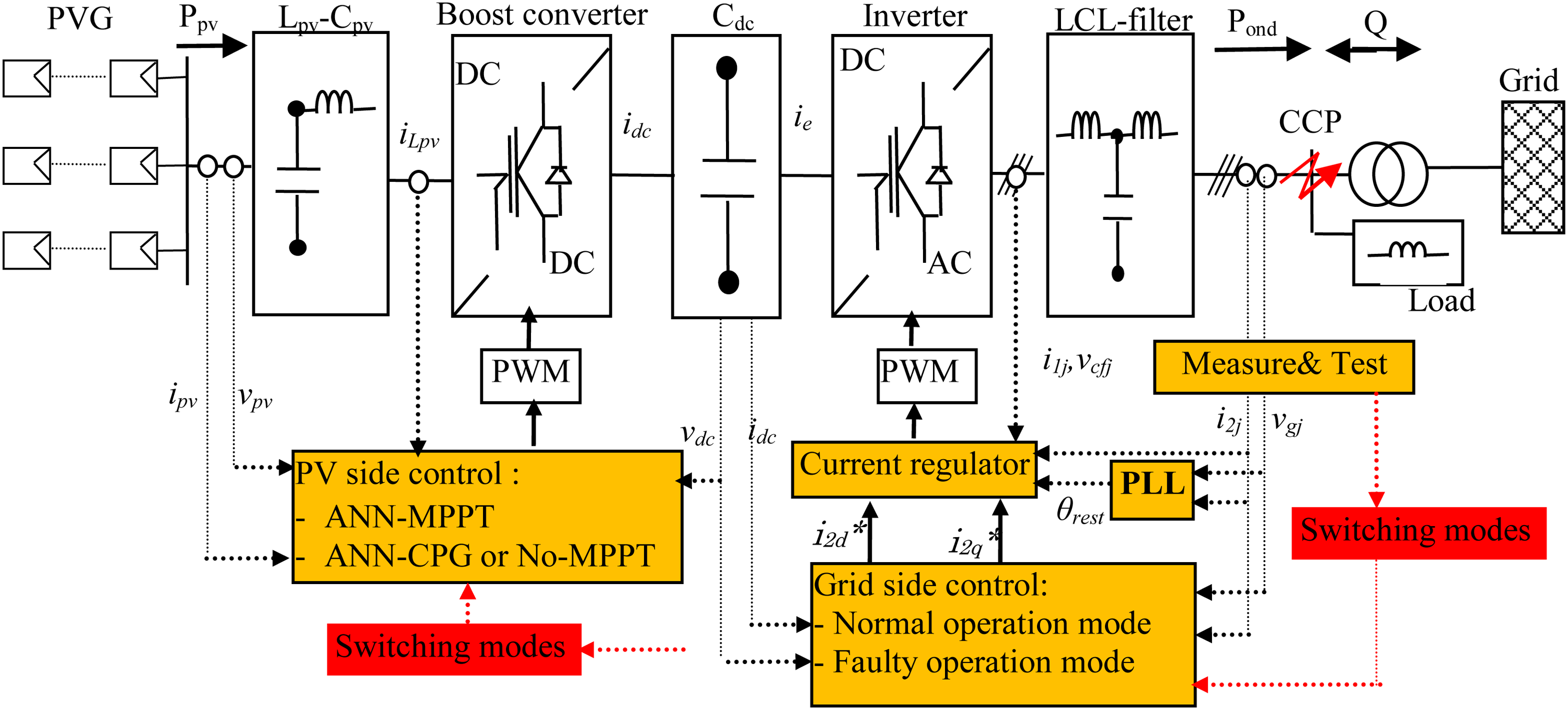
Basic scheme of the grid-connected PV system and its control structure.
A control unit, composed of PV-side and grid-side blocks, is proposed to control the overall system in its various states. Under normal operation mode (NOM), the control unit is composed of a grid voltage detection, a power block, current controllers, and an MPPT command. Under grid sags, a switching unit is used to change the operational modes; from NOM mode to LVRT mode once BGVD appears (Ding et al., 2016; Hamrouni et al., 2019; Yang et al., 2014). Hence, new active and reactive power references are calculated according to the grid codes and levels of voltage dip. The control algorithm of the grid-side is discussed in Manganiello et al. (2013), whereas the control of the PV-side boost converter is developed in this paper. In this case, a CPG command is calculated around the DC-DC converter. Its main goal is to calculate the new reference voltage (vpv*) related to the injected active power. If the PV power cannot be delivered to the grid and the DC-link voltage cannot be constant, the ANN-MPPT should switch to the ANN-CPG command. This command is proposed to adjust the DC-link voltage by means of the control of the PVG, which allows the PV plants to operate below the MPP. Figure 1 shows the basic configuration of the grid-connected PV system and its control structure.
Proposed DC-DC converter control
The proposed control strategy of the DC-DC converter is composed of two operational modes (Figure 2). They are the MPPT mode and the CPG or No-MMPT mode. The main objective of these commands is to adjust the output voltage of the PVG (vpv) to its reference value (vpv*) and to deliver the appropriate power to the alternative side. In these operation modes, the approach command matches the inverter output power to the PV power and keeps consequently the DC-link voltage constant. Under instantaneously BGVD, the current delivered by the inverter increases to keep the power balanced (Manganiello et al., 2013); however, this current is limited by the maximal output current of the inverter (Imax). Therefore, the active power injected into the grid (Pinv) decreases, while the MPPT command continues to extract the maximal PV power (Ppvm). A power imbalance appears between production and consumption in the system. Therefore, the excess power will be stored in the DC-link capacitor, which leads to an increase of the DC-link voltage to a new value above its reference. As an alternative, the connection under grid sags can be achieved by modifying the control of the PVG to operate below the MPP. Hence, the MPPT algorithm is replaced by a flexible command to comply with these requirements and keep the connection as long as possible. The goal of the command approach discussed in this paper is to find the new reference voltage (vpv*) corresponding to the LVRT operation mode. The operating power point of the PVG should be moved to a lower power level to protect the inverter switches and to avoid a DC link overvoltage. Therefore, the PVG should inject continuously variable active power according to the state of the grid at the CCP. The command moves the MPP to new operation points in order to achieve a balanced power between production and consumption. The reference powers are calculated based on the level of grid sag and the nominal current of the inverter. It can be equal to zero by opening or short circuiting the PVG (Mirhosseini et al., 2013). The active power injected by the inverter under BGVS is equal to:

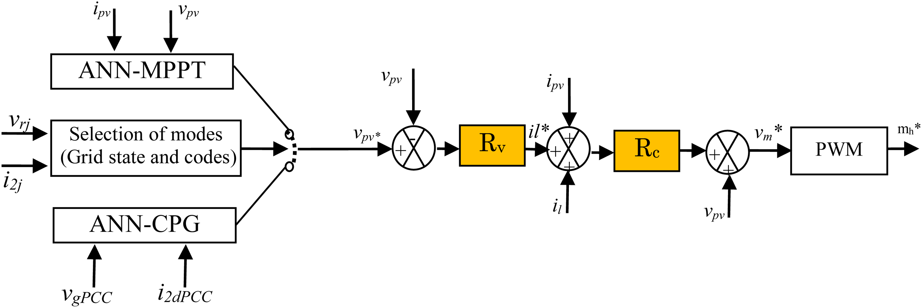
Control structure of the boost converter.
VgPCC and I2dPCC are, respectively, the grid voltage and the inverter current d component at the PCC.
The block diagram of the proposed command of the PV-side converter under normal and LVRT operation modes is given in Figure 3. When the set point under grid sag is below the MPP, the ANN-MPPT is employed but when it is above, the ANN-CPG is employed (Figure 4). The operating zone depends on the irradiance changing speed and the level of grid voltage dip.
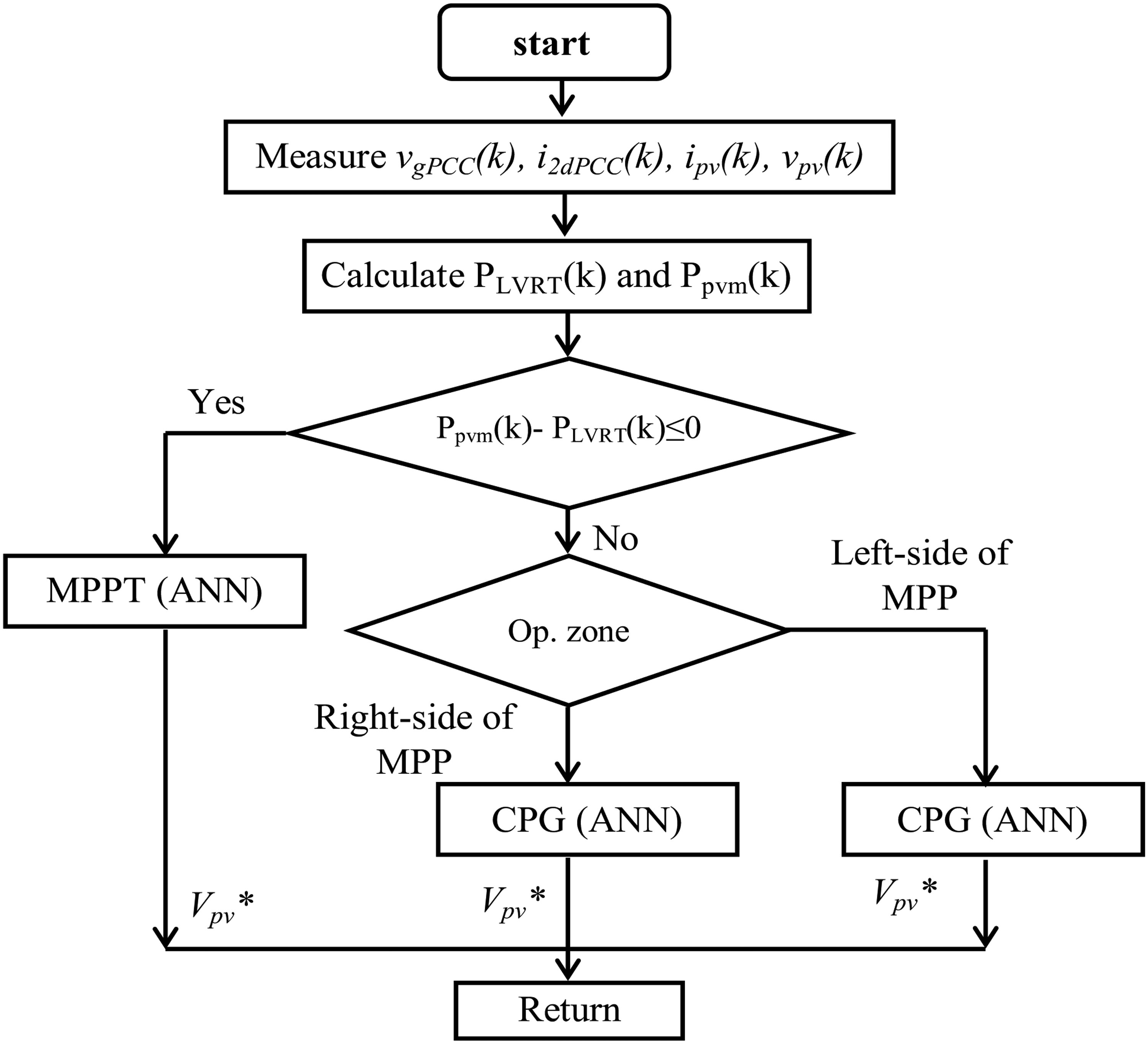
Block diagram of the proposed algorithm of the PV-side converter.
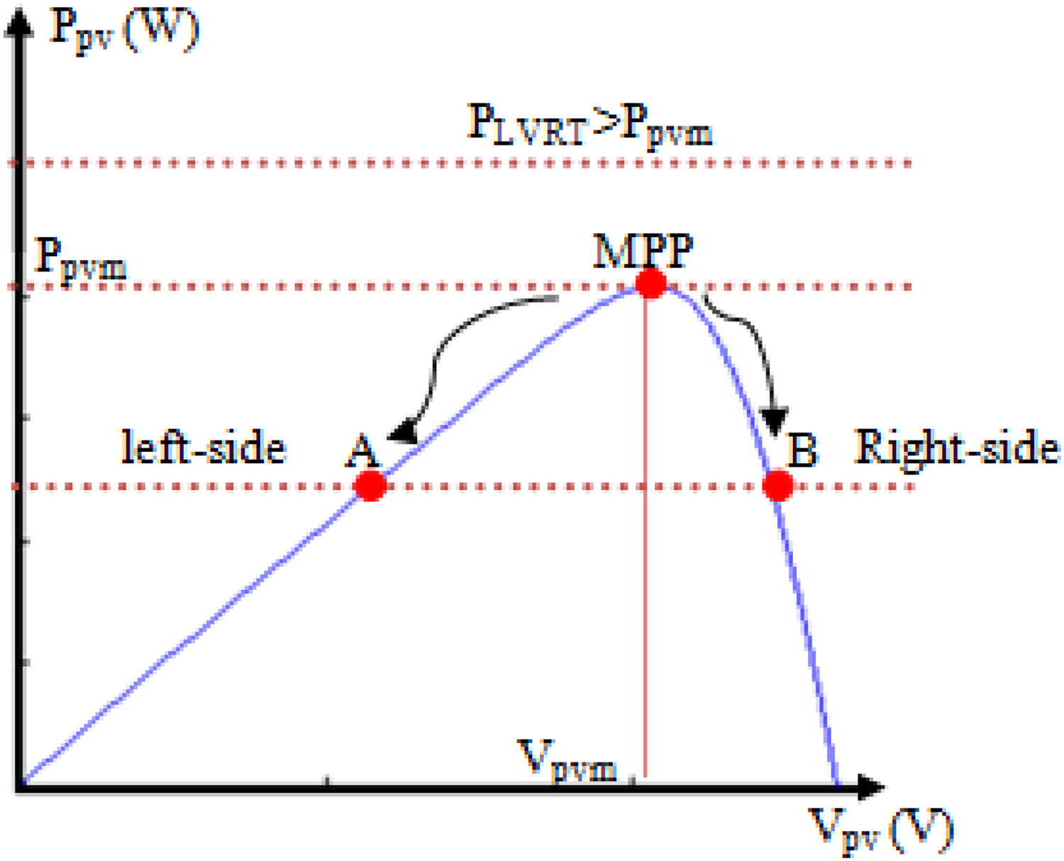
P-V curve of PVG (MPP) operation at maximum power. (a) operation at left side and (b) operation at right side.
ANN-MPPT under normal operation mode
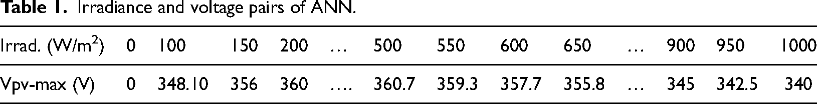
Various MPPT algorithms are used to maximize the PV generation and to increase consequently the efficiency of the grid-connected PV system. These algorithms differ in the efficiency, complexity of implementation, and speed of MPP tracking. The perturbation and observation (P&O) and incremental conductance are most commonly used to track the MPP; however, the ANN-MPPT is more efficient under both static and dynamic conditions (Manganiello et al., 2013; Reinhardt et al., 2015; Ricco et al., 2014; Sangwongwanich et al., 2016; Sera et al., 2013; Tey and Mekhilef, 2014). Several ANN architectures are presented in the technical literature, but the most used is the architecture-based three layers. These are the input, hidden, and output layers. The number of nodes in different layers varies with the level of learning and precision. For MPPT applications, the input variables of the ANN can be the metrological data (irradiance and ambient temperature) or the PV characteristics (open-circuit voltage and short-circuit current). Furthermore, the outputs can be the duty cycle, the PV current, or voltage corresponding to the PPM. In this work, an ANN-MPPT composed of three layers is considered (Figure 5). The first layer contains the irradiance, the second layer contains 10 neurons, and finally, the output layer contains the maximal PV voltage (PPM). In Table 1, listed are the input and output pairs of the desired ANN. The effect of the ambient temperature on the MPP is ignored.
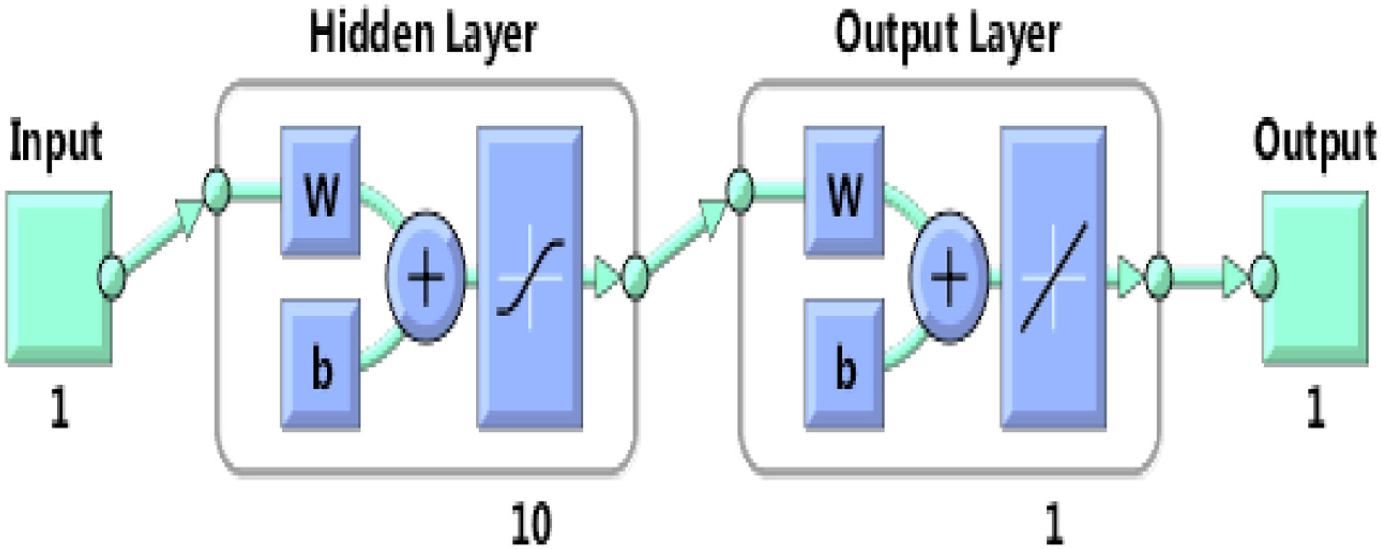
The ANN-MPPT architecture under normal grid conditions.
Irradiance and voltage pairs of ANN.
ANN-CPG under BGVD
According to the P-V characteristic given in Figure 4, two operation points are possible. The first is at the low voltage (on the left side of MPP); however, the second is at the high voltage (on the right side of MPP). Each of these operation points presents advantages and disadvantages. In fact, the moving of the MPP to the right side is faster than to the left side. Moreover, a higher oscillation of the PV power on the right side compared to the left side. On the right side, the operation point can go beyond the open circuit voltage (Voc) under fast changing climatic conditions. Therefore, the PVG becomes enabled to deliver power to the grid [20]. In this case, the command should perturb the operation point to move it to the left side. Otherwise, on the left side, the MPP presents poor control and a large oscillation of PV current and voltage when high grid sags occur at the CCP. According to the P-V characteristic, the dynamic performance is slower, whereas the oscillation of the PV power is less than on the right side. In fact, the use of configuration-based two-stage allows the possibility to operate on the two sides. This possibility is limited in the single stage because the operation point should usually move to the right side of the MPP. To overcome the drawbacks, an ANN-CPG algorithm is developed to control the PVG at the left and right sides when BGVD occurs at the CCP.
According to Figure 6, the photovoltaic power is given by: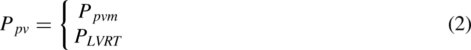
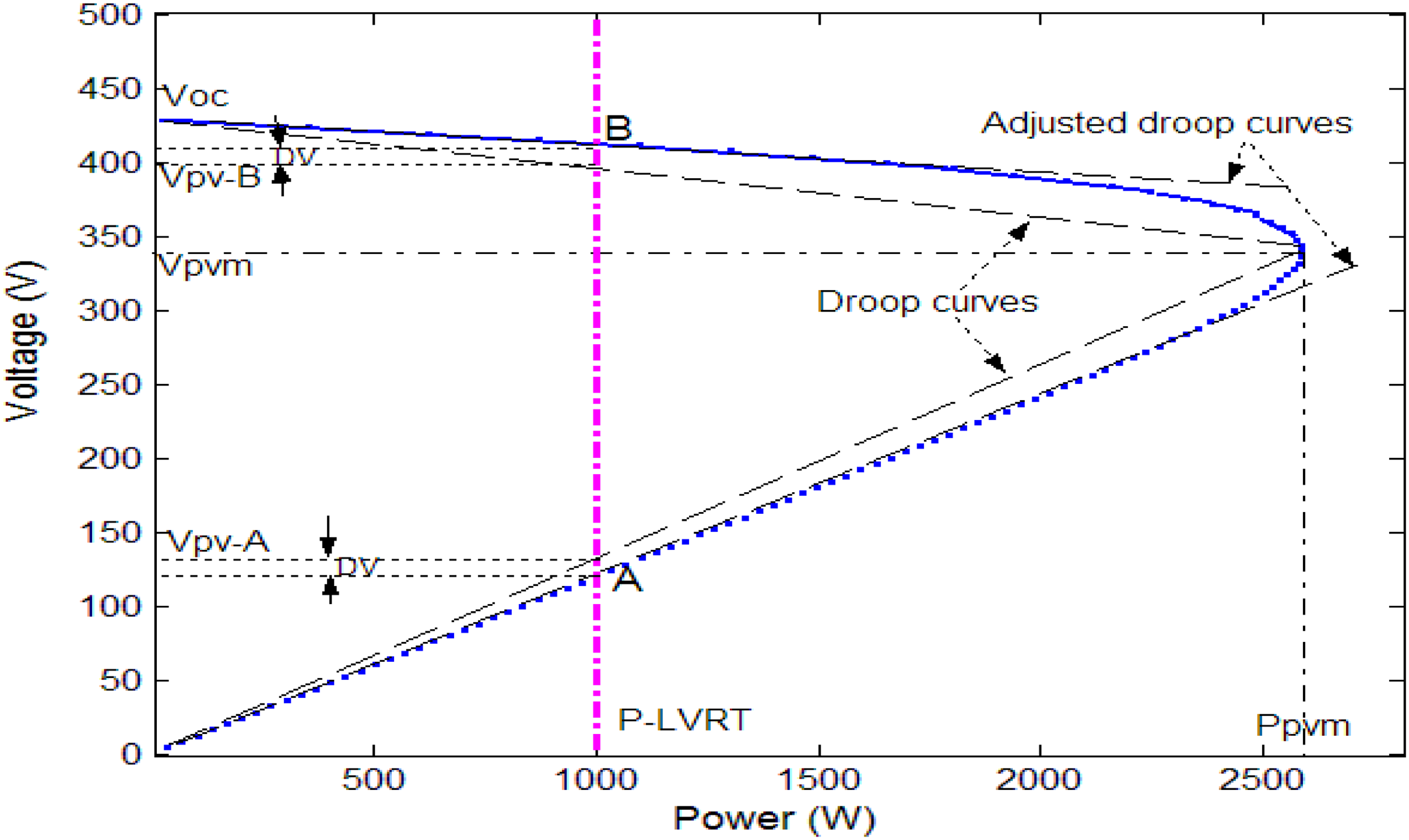
P-V characteristic of the PVG, the droop curves and operation points.
Ppvm and PLVRT are the PV powers provided, respectively, by the generator under normal grid condition and BGVS. The control strategy of the grid-connected PV system is based on the assumption that the photovoltaic power is equal to the inverter output power (conduction and switching losses are assumed to be zero). Hence, the corresponding reference voltage is given by: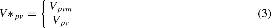
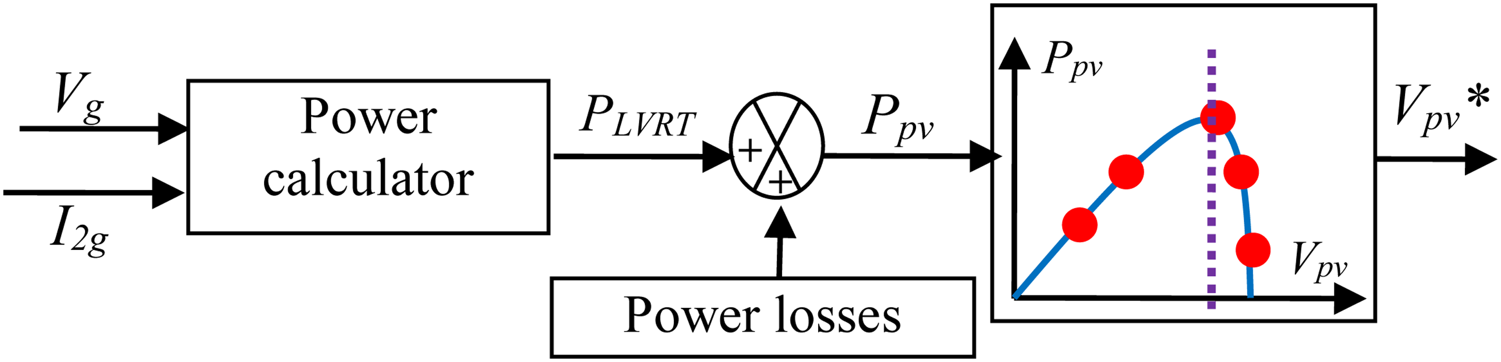
Diagram scheme of the CPG command.
Operation point at the right side of MPP
According to Figure 6, A and B are the operation points under LVRT mode. The grid-connected PV system can be controlled at both points. Therefore, the PVG has to reduce its power injection under grid voltage sag. As indicated by Figure 6, the P-V characteristic on the right side of MPP can be supposed linear. Under grid sags, the operation point should move from the MPP (Ppvm, Vpvm) to a lower power point named B (PLVRT, Vpv−B). According to the Side Splitter theorem [14] and the assumption given previously, the new reference voltage is given by:
Irradiance and P-V droop coefficient pairs of the ANN-CPG at right side.
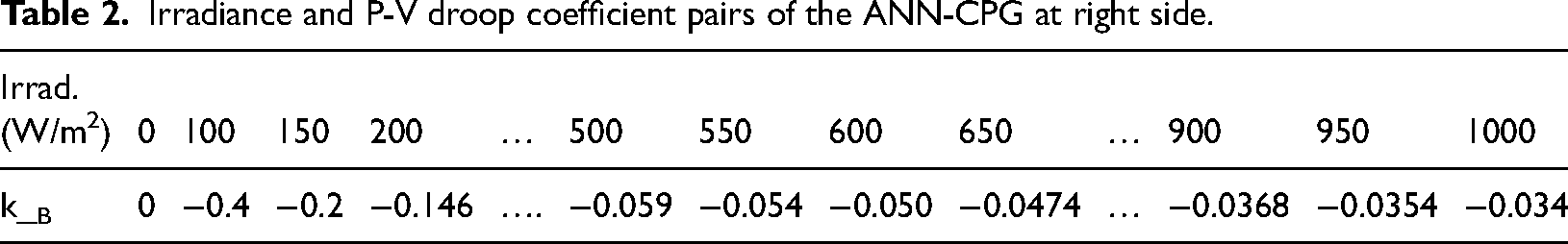
According to Figure 6, the P-V droop coefficient is approximated because the operating point (B) varies with the droop curf. In fact, the real operating point in LVRT mode is slightly different from the MPP because it varies with the adjusted droop curves. Hence, to alleviate this impact, the reference voltage on the right side can be adjusted according to Figure 6. It is given by:
Operation point at the left side of MPP
According to Figure 6, the P-V characteristic of the PVG has an approximately linear droop relationship in the LV zone (at the left side of MPP). The voltage corresponding to the PLVRT is expressed as follows:


Design of the PV current and voltage controllers
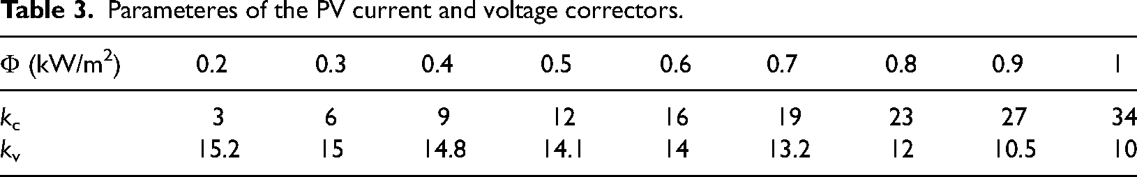
By means of measure and test blocks, the ANN-MPPT command switches to the ANN-CPG command to calculate the new reference voltage based on the state of grid at the CCP. The reference voltage will be used by the boost converter controller to calculate the command signals. Notably, under various operation modes, no modifications are required to the PV current and voltage controllers. According to Figure 1, the voltage control loop with the PV current compensation provides the reference current (il*), while the current control loop with the PV voltage compensation gives the reference voltage (vm*) for PWM. Rc and Rv are, respectively, the PV current and voltage controllers. They were designed to ensure a constant PV voltage and minimum current ripple. To improve the performance of the PV current and voltage controllers further, the tuning parameters of the controller are adaptively changed based on a precalculated look-up table according to the real-time value of the climatic conditions. Table 3 illustrates, respectively, the gains kc and kv of current and voltage correctors calculated for each 100 W/m2 solar radiation step.
Parameteres of the PV current and voltage correctors.
Simulation
For the first scenario, an irradiance profile that contains a step increase and decrease is shown in Figure 8. It permits to demonstrate the performance and efficiency of the proposed ANN-CPG algorithm. Accordingly, the required power reference and the maximum PV power under ANN-MPPT are depicted in Figure 8(b). According to this figure, there are many instances that the maximum PV power is lower than the reference power given by the alternative side.
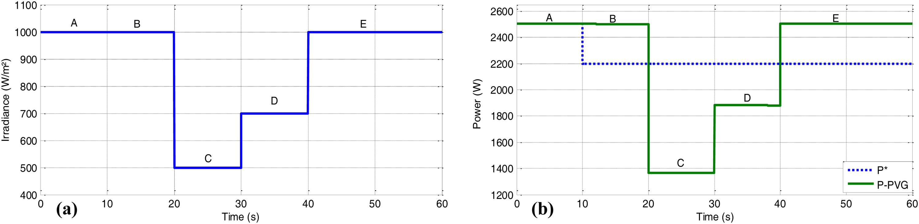
Scenario number 1: (a) irradiance profile, (b) available PV power and reference power.
Test performance at right side of MPP
This paragraph studies the performance of the ANN-CPG algorithm on the two-stage grid-connected PV system when the operation point moves to the right side of MPP (Figure 4):
Before t = 10 s (Point A), the irradiance is equal to 1 kW/m2. The two-stage grid-connected PV system operates under normal conditions. The reference power is equal to the maximum PV power (≈2.5 Wp), whereas the corresponding PV voltage and current are, respectively, 340 V and 7.6 A. The boost output current reaches 5 A and the corresponding duty cycle is 0.35. Between t = 10 s and t = 20 s, the reference powers have been changed due to the grid faults. Consequently, the maximum PV power became higher than the reference power (2.2 kW). Hence, the ANN-CPG regulates the reference PV voltage to 356 V, which keeps the operation point of PVG at point B. The corresponding PV current decreases to 6.2 A (Figure 9(b)), and the boost output current reaches 4.2 A (Figure 9(c)). The duty cycle decreases to 0.315 to ensure the system operation under BGVD (Figure 9(e)). Between t = 20 s and t = 40 s, the PVG operates at the MPP because the maximum power provided by the PVG generator under 500 and 700 W/m2 is smaller than the reference power. The new operation points are, respectively, C and D. After t = 40 s, there is a step increase of irradiance. The operating point D moved quickly to point E with an increase of PV voltage (Vpv = 340 V). The operation of the grid-connected PV system at point E is the same operation as point B.
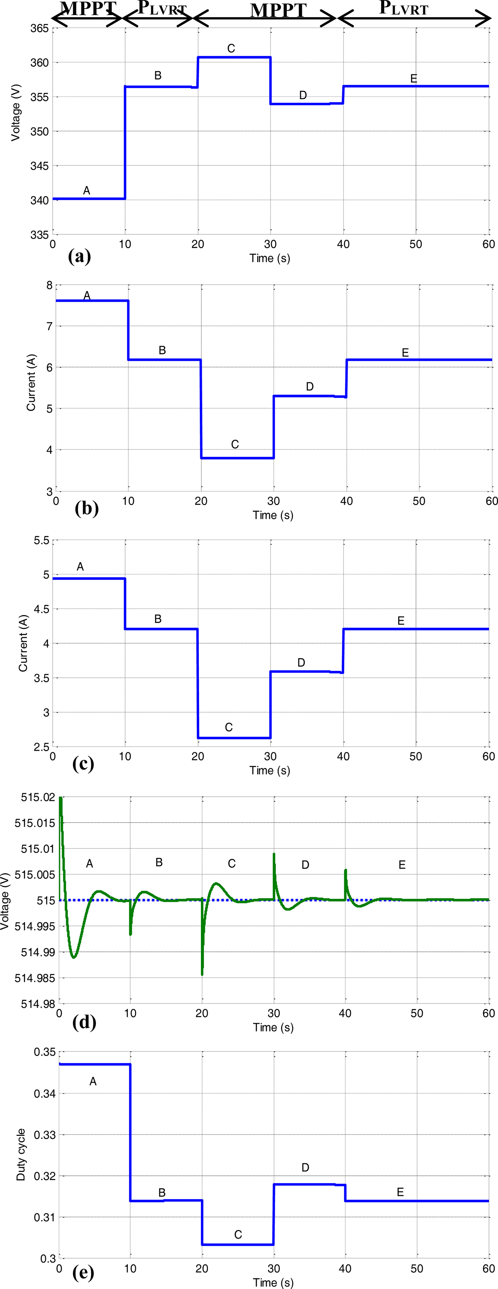
Variable power generation of the PVG with the movement of the reference voltage on the right side of MPP: (a) Reference PV voltage (vpv*), (b) PV current (ipv), (c) DC current (idc), (d) DC-link voltage (Vdc) measure and reference and (e) duty cycle of the DC-DC converter.
To ensure a constant DC-link voltage (Figure 9(d)) and consequently protect the inverter, the ANN-CPG algorithm decreases instantaneously the DC current provided by the boost converter when the reference power is smaller than the available PV power (Regions B and E). Due to ANN-MPPT and ANN-CPG algorithms, the response is very fast, and there is no oscillation in the various characteristics of the system (Figure 9).
Test performance at left side of MPP
The second test scenario discusses the performance of the ANN-CPG algorithm for the movement of the operation point to the left side of MPP. Figure 10 presents the test performances of the algorithm. The irradiance profile is the same as given in Figure 8(a). Before t = 10 s, the PVG operates at point A (MPP) with Vpv = 340 V and Ipv = 7.6 A. Due to the BGVD which appears at t = 10 s, the ANN-MPPT command switches to the ANN-CPG command which moves the operation point from A to B. Between t = 20 s and t = 40 s and due to the decrease of irradiance, the PVG operates at its MPP because the reference power is higher than the available PV power. A similar process as presented in the first case (Para. IV.1) is performed in this part.
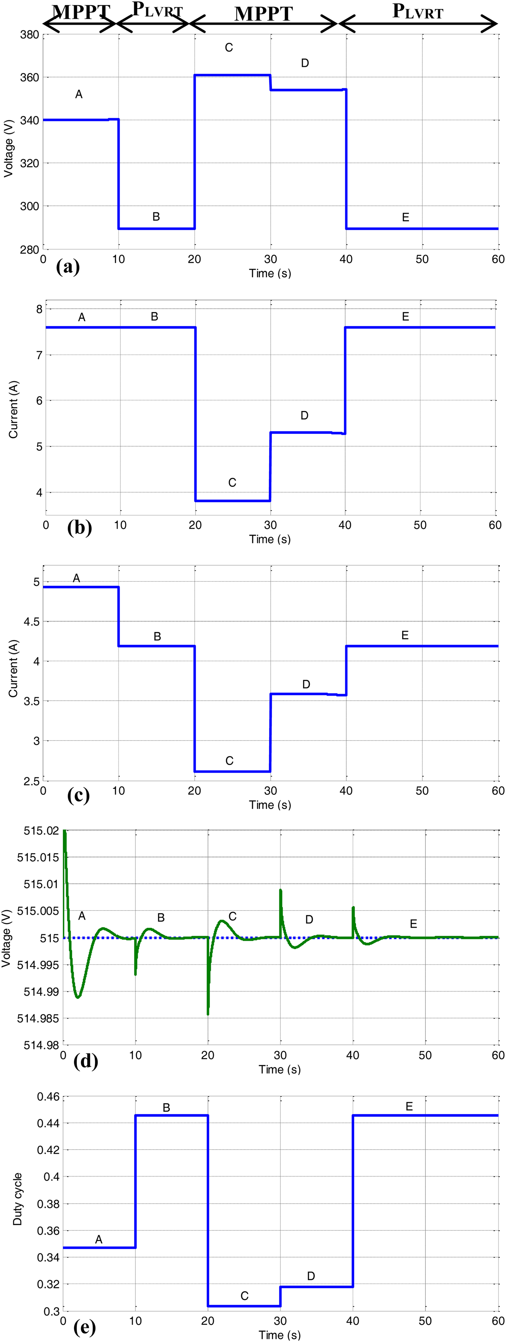
Variable power generation of the PVG with the movement of the reference voltage on the left side of MPP: (a) reference PV voltage (vpv*), (b) PV current (ipv), (c) DC current (idc), (d) DC-link voltage (Vdc) measure and reference, (e) duty cycle of the DC-DC converter.
The operation points of the grid-connected PV system under LVRT and MPPT commands are depicted in Figure 11. It can be seen that the LVRT operation points are at right side (Figure 11(a)) and left side of the MPP (Figure 11(b)) represented by point A.
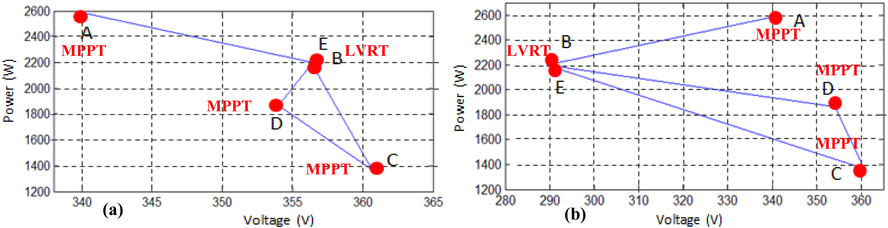
Operation points of the PVG at right-side and left side of MPP.
Test performance under variable reference power
In this part, the performance of the ANN-CPG command is presented under various levels of BGVD. For this scenario, a reference power profile that contains a step increase and decrease is shown in Figure 12(a). A fast and severe decrease of reference power (P*) has been occurred at t = 10 s. Consequently, the operation control is switched from ANN-MPPT to ANN-CPG mode. From point B to point E, a step change of reference power is made for each 10 s. At point F, a clearance of grid fault occurs. Consequently, the operation control switches from CPG to MPPT.
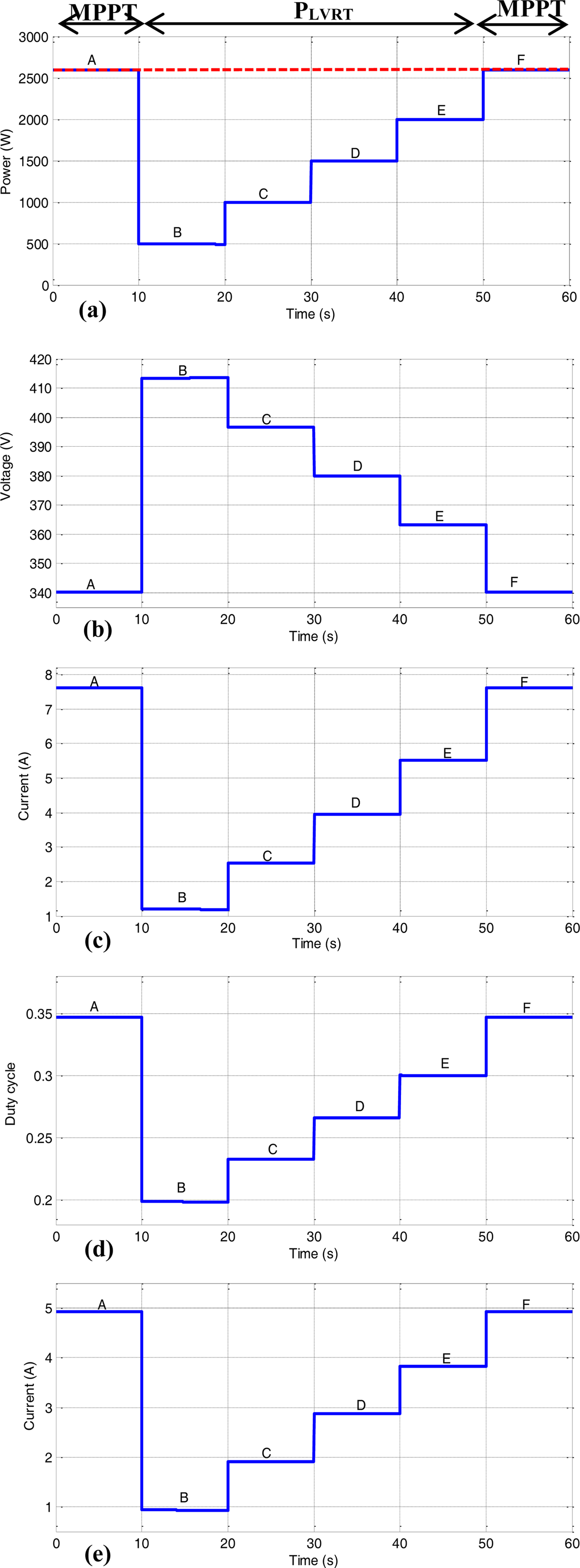
CPG of PVG with variable reference voltage at right side of the MPP: (a) Available PV power and reference power, (b) PV voltage reference (vpv*), (c) PV current (ipv), (d) duty cycle of the DC-DC converter and (e) DC current (idc).
Figures 12 and 13 present the results of test scenarios performed on the two-stage grid-connected PV system. Before t = 10 s, the grid-connected PV system operates under normal grid condition and ANN-MPPT algorithm (Point A). After this time, the operation mode should change because the reference power imposed by the grid became equal to 500 W. Hence, the ANN-CPG moves quickly, the PV power to point B. Consequently, at the right side of MPP, the ANN-CPG algorithm increases the PV voltage to 414 V (Figure 12(b)) and decreases the PV current to 1.2 A (Figure 12(c)). Moreover, to maintain the balance between power and the DC-link voltage at 515 V, the boost output DC current decreases to 1 A (Figure 12(e)). On the left side, when a BGVD occurs at t = 10 s, the PV voltage decreases to 55 V; however, the PV current is still constant, and the DC current reaches very low values (0.9 A) to maintain the balance power, respectively, at left side and right side. A similar process as point B is performed for points C, D, and E on the two sides. After t = 50 s, the system regains the NOM (Point F).
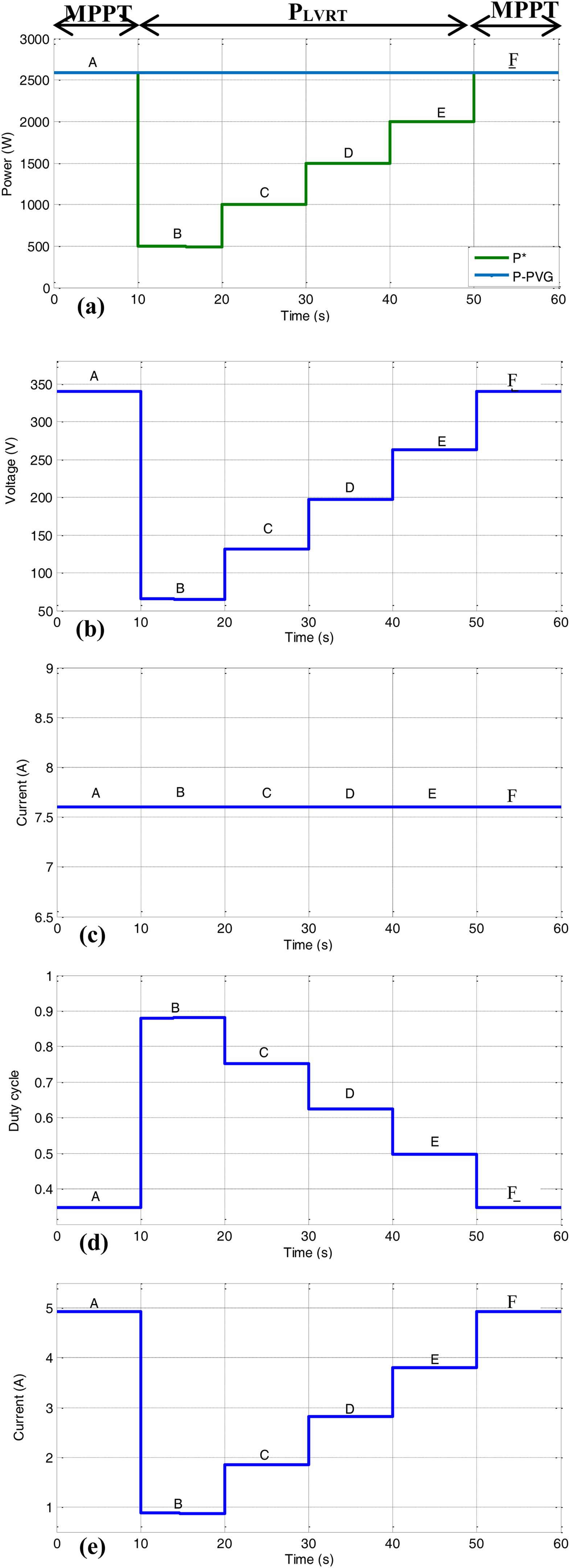
CPG of PVG with variable reference voltage at left side of the MPP: (a) available PV power and reference power, (b) PV voltage reference (vpv*), (c) PV current (ipv), (d) duty cycle of the DC-DC converter, and (e) DC current (idc).
Conclusion
An ANN-algorithms have been introduced in this paper that regulates the output PV power under normal and BGVDs. The ANN-MPPT algorithm is used to control the operation point of the PVG under normal grid conditions to extract the optimal PV power. An improved LVRT control algorithm based on ANN-CPG is proposed to control the PVG under grid fault transition. The ANN-CPG algorithm uses the P-V characteristics to calculate the reference PV voltage corresponding to a certain value of power when grid faults occur. The performance of the proposed algorithm has been evaluated under various conditions such as variation in climatic conditions and severe BGVDs. Based on the simulation results, the algorithm is flexible to move the operation point to the left or right side of MPP. It ensures fast dynamics and no power oscillations in a steady state and achieves CPG and stable operation under grid faults. In addition, we have shown that it is possible to maintain instantaneously the inverter's operation in presence of BGVD and consequently it becomes possible to supply the local load in the absence of storage devices. However, some limitations of the proposed control are recorded:
The PV power is reduced when changing from ANN-MPPT control to ANN-CPG control. The security of the grid-connected PV system is not guaranteed, especially under imbalanced grid fault dips.
The perspective of this work will concern the capability of the proposed command to operate under partial shading and imbalanced grid fault dips.
Footnotes
Declaration of conflicting interests
The author(s) declared no potential conflicts of interest with respect to the research, authorship, and/or publication of this article.
Funding
The author(s) received no financial support for the research, authorship, and/or publication of this article.