
Abstract
In order to obtain the flow trend of particles in the shaft coal pocket, Lay a foundation for the research on the stability of shaft coal pocket wall in coal mine. The flow trend of particles in the process both coal unloading and sand unloading is studied. The study methods are used by physical similarity simulation and numerical simulation experiment. The results show that the loose particles are divided into “three zones” in the longitudinal direction. As a whole, the particles in the shaft coal pocket is characterized by “two circles” which is the axis area and the bunker wall area. The better fluidity in the core, but the worse fluidity close to the bunker wall. The flow trend of the particles in the middle warehouse is as follows: the particles in the smooth passage in the central area flow out first. After flow out, the particles in this area will be filled by the particles in its upper area, then the outflow continues, the loose particles in the outer area of the middle flow out last. The particle flow trend in the natural flow area under the bearing structure is as follows: the loose particles in the funnel under the structure flow out according to the natural state. Due to the protection of its upper conical shell structure, the pressure of loose particles in this area are smaller than the upper area. which shown random natural outflow when coal outflow. The flow trend of bulk in the silo is basically consistent with the experimental results of numerical simulation.
Introduction
The shaft coal pocket is the key passage of underground coal mining. Its main function is to store and release the loose particles in the bunker and balance the main transportation system of the mine. The premise of study the stability of the shaft coal pocket wall is to understand the flow trend of loose particles in the bunker. The shaft coal pocket project in the coal mine site is particularly huge, and the environment in the bunker is bad. So it is very difficult to observe the flow pattern of internal loose particles in the production process. Therefore, in this paper, physical experiments combined with particle flow numerical experiments are used to study the flow trend of bulk in shaft coal pocket. It have great significance in guiding mine production and mine design.
In 1875, Rankine put forward the viewpoint of active equilibrium state and passive equilibrium state according to the limit equilibrium of micro element, which laid the foundation of bulk medium theory. Walker and Walters also did some work on the assumption based on the pressure state of bulk. Walker considered the friction between bulk and warehouse wall and modified the Rankine side pressure coefficient in active state(Walker, 1966; Walters, 1973). Jenike pointed out the respective deformation characteristics of the bulk in the active state and passive state(Jenike et al., 1973). When unloading, the bulk began to gradually change from the active state to the passive state from the lower part of the bin. Due to the balance relationship of the bulk weight, the warehouse wall generated overpressure at the conversion horizontal plane and moved up with the conversion surface. On the basis of a large number of experiments and starting from the difference equation, Reimbert proposed that the horizontal pressure distribution is in the form of hyperbola(Reimbert and Reimbert, 1976). Gentzis and others believe that the stability of underground tubular structure is affected by its diameter, and the smaller the diameter, the more conducive to stability(Gentzis et al., 2009). Meng Analyzed the soft rock stratum of coal mine by numerical analysis method and detected the deformation of surrounding rock(Meng et al., 2015). There are also on-site engineering practice of studying and guiding the deformation law of buildings and surrounding rocks in underground engineering(Yang et al., 2017; Kang et al., 2014; Liang et al., 2017). According to the failure characteristics of coal gangue, Xin proposed that the strain curve of loose coal gangue increased linearly in the initial stage(Xin et al., 2020). Other scholars have studied the estimation of lateral pressure and stress distribution of cylindrical cylinder wall(Bai et al., 2014; Wang et al., 2010; Cheng et al., 2021; Yin et al., 2018). Edwards and Oakeshott proposed the phenomenon of arching in bulk particles(Edwards and Oakeshott, 1989). Yang analyzed the in-situ stress distribution characteristics of coal mine(Yang et al., 2015). Khan evaluated the aging mine barrel wall structure(Khan et al., 2002). Nguyen analyzed the discharge process of conical hopper(Nguyen et al., 1980). Atevologun tested the wall pressure of the warehouse with soybean particles as the storage material(Atevologun and Riskoski, 1991). Brown conducted numerical analysis on the unloading process in the warehouse(Brown, 2008).
Wu et al. conducted a series of research on the shaft coal pocket wall in coal mine, and used to the practice(Wu et al., 2020, 2021, 2022; Liu and Wu, 2017; Liu and Wen, 2021). Based on the analysis of the causes of the damage and collapse of the shaft coal pocket in coal mine, the team proposed the composite support scheme of “anchor cable net + inner sleeve double-layer reinforced concrete bunker wall”, filled the collapse space behind the wall with concrete, specially treated the rock stratum in the aluminum mudstone section, and gave the effect evaluation. Successfully completed the shaft coal pocket wall repair project of Ganhe coal mine(Liu and Wu, 2017); The mechanical model of shaft coal pocket wall of coal mine is established, and its deformation characteristics are studied; From the internal structure of loose particles in the shaft coal pocket of the coal mine, the bearing characteristics of the bunker wall are analyzed, and the unloading process of the shaft coal pocket of the coal mine is simulated combined with the numerical simulation experiment and three-dimensional physical similarity simulation experiment. It is proposed that there is a “three-dimensional conical shell” bearing structure in the unloading process of loose particles in the bunker(Wu et al., 2020, 2021; Liu and Wu, 2017; Liu and Wen, 2021); The concept of “weak rock stratum” is put forward for the shaft coal pocket project that longitudinally crosses multiple rock strata, and it is pointed out that the existence of this rock stratum is an important inducement for the failure of shaft coal pocket wall(Wu et al., 2022). Physical analogue simulation and numerical simulation experiment are important research methods in mining engineering(Qian et al., 2021).
At this stage, Few studies on the flow trend of loose particles in the shaft coal pocket, so it is necessary to use effective research methods to master the flow trend of loose particles in the shaft coal pocket. At home and abroad, the research on the shaft coal pocket from the perspective of granular particles has not been retrieved yet. This paper try to study the loose particles in shaft coal pocket of coal mine. Therefore, the research in the shaft coal pocket has important practical and scientific significance for guiding the actual production of the mine engineering, mine design and study on the stability of the shaft wall.
“three dimensional cone” bearing structure in the flow process between bulk particles in the silo
Physical experiment process
The safety accidents caused by the deformation and failure of the shaft coal pocket wall of the coal mine happens frequently, and they have never been stopped. The research and application of the deformation and failure of the shaft coal pocket wall of the coal mine has become a major weakness under the general trend of the development of intelligent mine. The fault types of shaft coal pocket are mainly divided into two categories: functional fault (such as difficult unloading, bunker blocking, etc.) and structural fault (such as shaft wall damage, chamber damage, etc.). Through the experiments of loading and unloading coal with different simulated granular materials, the flow trend of granular coal and dry sand is studied.
Coal loading and unloading experiment process: transparent materials are used to simulate the shaft coal pocket wall, different rock layers are simulated by different similar material ratios, and the granular materials filled in the shaft wall are the same ratio as the coal seam. Many coal loading and unloading experiments are carried out to observe the flow trend and arching shape of loose particles in the bunker, record the flow state in the process of coal loading and unloading at the same times.
Sand loading and unloading experiment process: the bulk solid filled in the warehouse wall is simulated as dry river sand used in the laboratory. Through many sand loading and unloading experiments, observe the flow trend and arching of bulk particles in the warehouse. Observe the flow pattern and experimental phenomena during sand loading and unloading.
Observe the shape of granular flow:in order to accurately describe the spatial shape of the structure formed by the top coal during the discharging process, through the direct observation after making a section in the surrounding rock. Through the lower outlet, the shape of coal particles can be observed as conical shell. In the experiment, the borehole peep instrument is used to enter the shaft coal pocket from the bottom of the model, and the internal space shape when the bunker is blocked can be well observed. It can also measure the size, height and other parameters of three-dimensional conical shell.
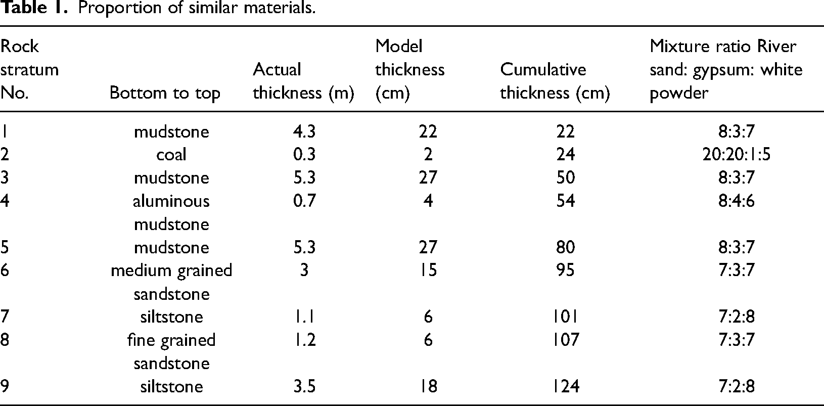
The ratio of similar materials for simulated rock stratum is as follows: according to the geological data of Ganhe Coal Mine, the mechanical parameters of each main rock stratum measured by the rock mechanics experiment in the laboratory. Based on the similarity relationship between the parameters of the prototype and the model, river sand, gypsum and white powder are selected as the experimental materials, and different ratios of similar materials are selected for different rock strata, as shown in Table 1.
Proportion of similar materials.
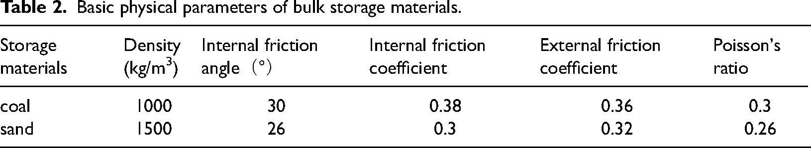
Material parameters for the experiment: In order to make the experiment match the actual situation, the bulk coal particles in the shaft coal pocket of the well are simulated with similar materials with the same proportion as the rock stratum, crushed into granules, and its unit weight is 1000 kg/m3, which is basically equivalent to the unit weight of the coal particles stored in the actual bunker; In order to analyze the influence of different loose materials on the silo wall, dry sand is used as different kinds of loose materials to form a contrast experiment with coal particles, with a unit weight of 1500 kg/m3, which is equivalent to the unit weight of the coal gangue mixture in the actual silo. Then the coal bunker volume is about: V = πR2h = π × 0.22 × 1 = 0.125 m3; Weight of bulk coal: G = ρ V = 1000 × 0.125 = 125 kg, weight of loose sand: G = ρ V = 1500 × 0.125 = 187.5 kg. The basic physical and mechanical properties of granular particles used in the test shown as Table 2.
Basic physical parameters of bulk storage materials.
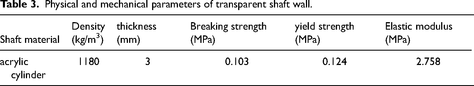
The mechanical parameters of the materials for the shaft coal pocket wall used in the experiment shown as Table 3.
Physical and mechanical parameters of transparent shaft wall.
“three dimensional cone” structure of bulk in physical experiment
The shape of the formed structure will be affected by which the bulk coal particle volume, particle size, bulk material properties and fluidity in the shaft coal pocket. The experiment records the arch phenomenon and times of each full silo of coal during each coal discharge. It is found that the structural shape of the bulk coal in the bunker is mostly in the shape of “three-dimensional conical shell”, moreover, the flow pattern and retained loose particles in the shaft coal pocket show the cone shape is a recurrent events.
The movement trend of loose particles in the bunker during coal caving: different loose particles have different effects on the development form of “three-dimensional conical shell”. It mainly moves downward and flows out sliding along the vertical direction. The main manifestations along the radial direction are overturning, rolling and sliding. The experimental study found that the loose particles caused structural blockage during the flow process in the silo. The internal shape of the structure is a three-dimensional cone, which can be called “three-dimensional cone shell” bearing structure, as shown in Figure 1.
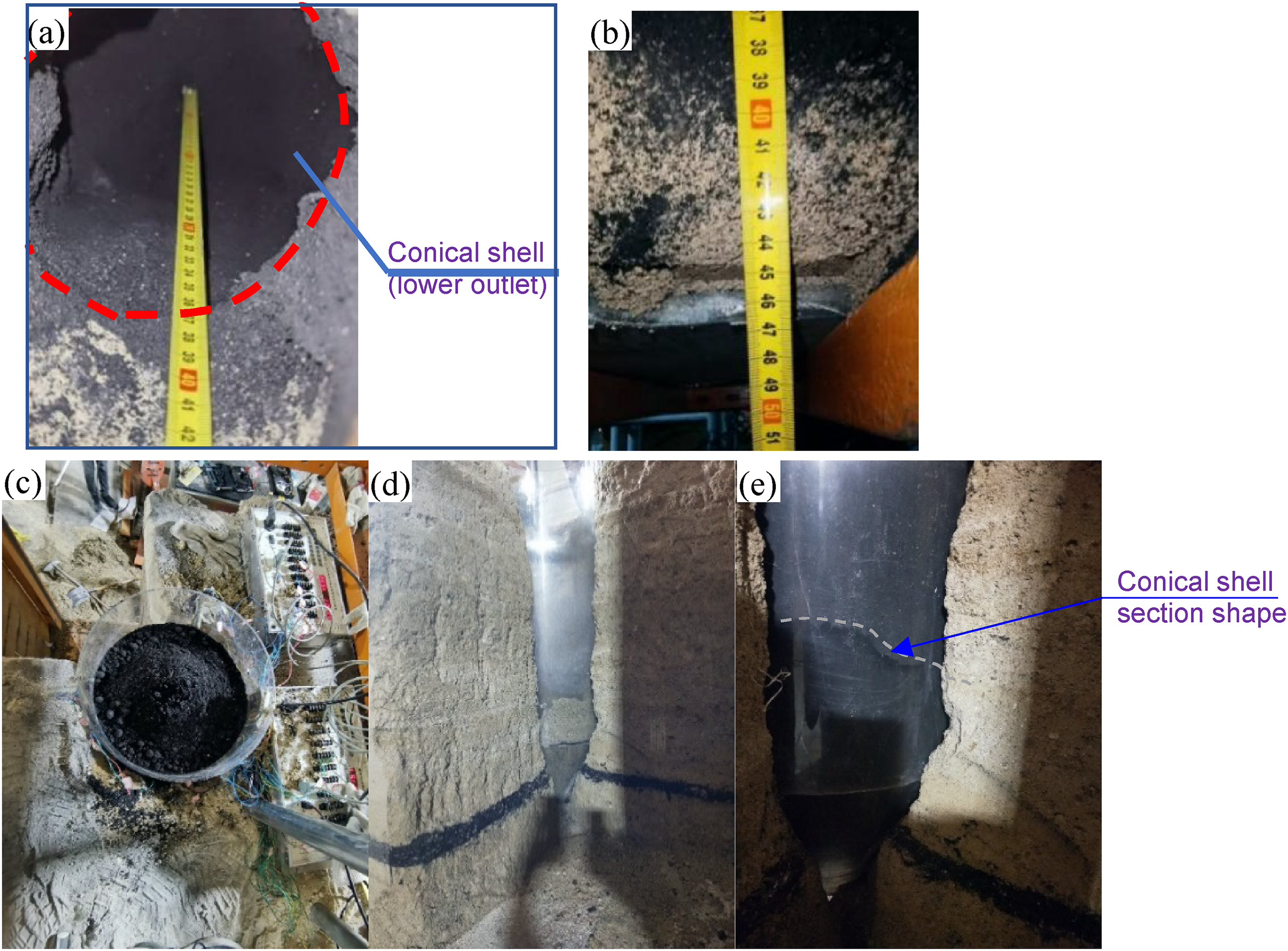
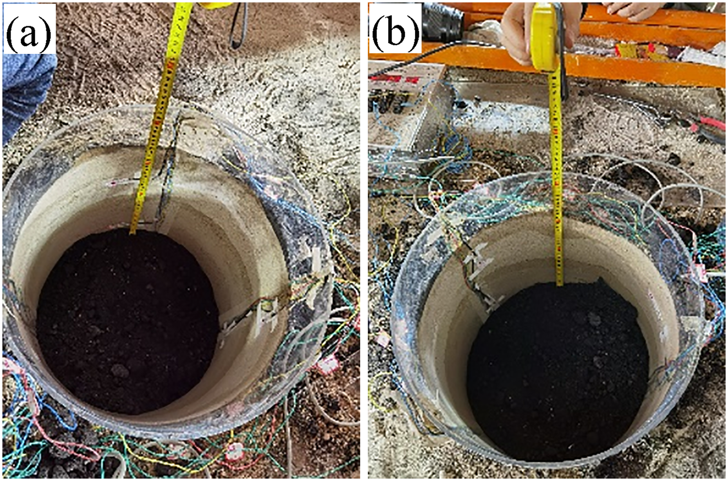
Observation form of lower opening during coal unloading.
Figure 1 shows the internal “three-dimensional conical shell” shape observed in the experiment. During the unloading process, when the lower area is arched, the maximum height is measured to be 37 cm. As the lower bulk particles are released, the upper particles do not move at this time due to the existence of structure. In order to further observe the whole flow process of bulk particles in the silo, the 1/4 section of the experimental surrounding rock model is made, the coal(sand) loading/ unloading experiments are carried out again. Due to the model of transparent shaft coal pocket wall, the flow of bulk storage materials in the silo can be observed more clearly, and it is also very convenient to observe the internal situation by cutting open the 1/4 surrounding rock.
After the lower part is dredged manually, it will continue to return to the flow state. In the experiment, it is also found that sometimes the loose particles flow in the shaft coal pocket will appear eccentric flow. It indicates that the instability of its internal structure is not necessarily in the center of the shell, but in a specific area at the top of the structure. This experimental phenomenon is shown in Figure 2.
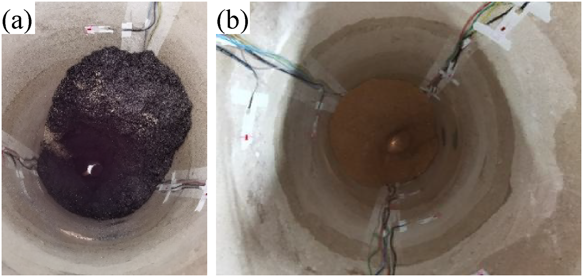
Experimental phenomenon of eccentric flow of bulk in silo (shell shoulder instability).
Figure 2 also shows that under the natural flow state of loose particles in the shaft coal pocket, the broken section is mostly conical surface. The surface from which a straight line rotates around the central axis, and a few central axes have deflection angles.
Structural form diagram of “three-dimensional conical shell”
When the lower export of the shaft coal pocket is opened, only a small part of the material can be discharged from the coal bunker due to internal arching. Then, the material stops flowing and the material particles form a structure above the discharge hole. The structure has an effect on the wall stress and the fluidity of bulk particles. Combined with the three-dimensional physical similarity simulation experiment of the transparent wall. When the particles in the warehouse are arched, the internal bulk particle bearing structure is formed. Therefore, it can be considered that the structure formed during the unloading process of bulk particles is the spatial distribution form of “three-dimensional cone”, as shown in Figure 3.
Three dimensional cone shape.
In Figure 3 which Ds——Diameter of the top of the conical shell, m; h0——Height of hopper at the bottom of shaft coal pocket, m; hq——Height of conical shell, m; β——Angle of conical shell body, °; hy——Height of cone top arc segment, m; βd——Angle of cone top arc segment, °; Rd——Radius of cone top arc segment, m.
The pressure variation of the shaft coal pocket wall is mainly determined by the movement of loose particles in the bunker and the bearing structure. This is because in the process of coal unloading, due to the friction force on the inner side of the silo wall, the particles flow in the area near the silo wall will slow down and flow out of the particles in the central area. So that the loose particles squeeze and rub with each other to form a bearing structure. When the bearing capacity of the structure is greater than the sum of the static and dynamic pressures of the upper storage materials, the arching phenomenon of bulk materials occurs, and the shape is “three-dimensional conical shell”. At this time, the warehouse blocking accident occurs. When the structure is unstable, the coal flow returns to the normal flow state.
Flow trend of loose coal particles in shaft coal pocket
The three-dimensional physical simulation test with transparent warehouse wall material can better and more intuitively observe the flow trend of bulk particles. When the coal (gangue) in the shaft coal pocket discharged, the particles under the structural protection area flow out fist, the space occupied by the discharged coal gangue in the bunker is a three-dimensional conical shell shape. The overall flow is the most ideal state, and whether the coal gangue close to the warehouse wall can be released freely depends on the fluidity of the bulk particles. If the fragmentation is uniform and the fluidity is good, the particles near the shaft wall will be discharged layer by layer with the decline of the flowing collapse funnel. When the inclination angle of the silo bottom is greater than the friction angle between the particles and the wall, it will discharge the bulk particles in the whole shaft coal pocket.
Whole flow of dispersed particles in shaft coal pocket
When unloading coal(sand) the upper particles will sink as whole flow. That is, during the unloading process, there is no dead material in the bin, and the stored materials are unloaded from the bin in the way of first-in-first-out (FIFO). All the bulk particles in the bin are moving, which will cause the dynamic side pressure of the shaft wall increased sharply. The test measured the first structural instability observed from the upper port, and instantaneous subsidence when the particles sink as whole flow, as shown in Figure 4.
Instantaneous sinking for the first time during overall flow.
Figure 4 shows that the situation after the first overall subsidence observed at the upper opening with the release of lower coal particles during coal unloading. It can be seen that the overall subsidence trace is the height of the soaked and wet part of the inner bin wall.
Figure 5 shows the descending height of the upper top surface of bulk particles in the shaft coal pocket.
Falling height of top surface of dispersed particles.
Figure 5 also shows that during the unloading process, the top surface of the bulk particles as a whole seems as a downward trend with the passage of time. But the bulk subsidence observed from the top surface is 0 during the period of 0–20s from the beginning of unloading, which basically remains in a stationary state. While there is a sudden trend of increasing the subsidence in 20s, which indicates that the internal arch structure loses stability for the first time with the outflow of the lower particles. In the upper part of the structure, the first overall sinking movement of the loose particles occurred. Continue unloading, the same phenomenon occurs again at about 40s, that is, the secondary instability of the structure. Then, at about 80s, the storage height was very small. At this time, the relationship between the sink height of the top surface and time basically shows a linear correlation. The fluidity of loose particles is the best until the particles are completely released.
Figure 6 shows that the fitting curve between the falling height of the top surface and time during the unloading process of the shaft coal pocket. The fitting equation is:
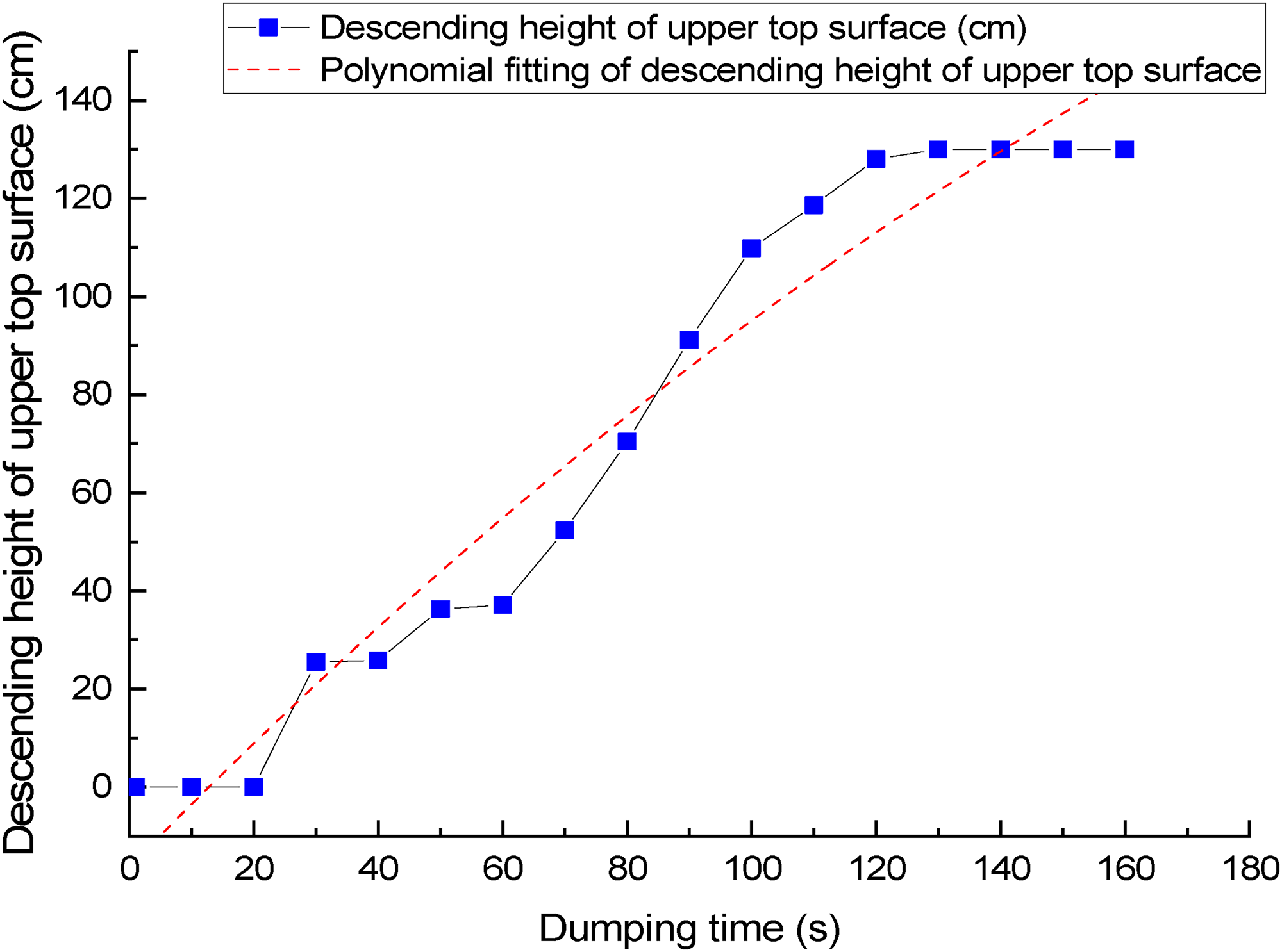
Fitting between top surface of dispersed particles and unloading time.
Where fitting R2 = 0.954。
Funnel-shaped flow of dispersed particles in the middle
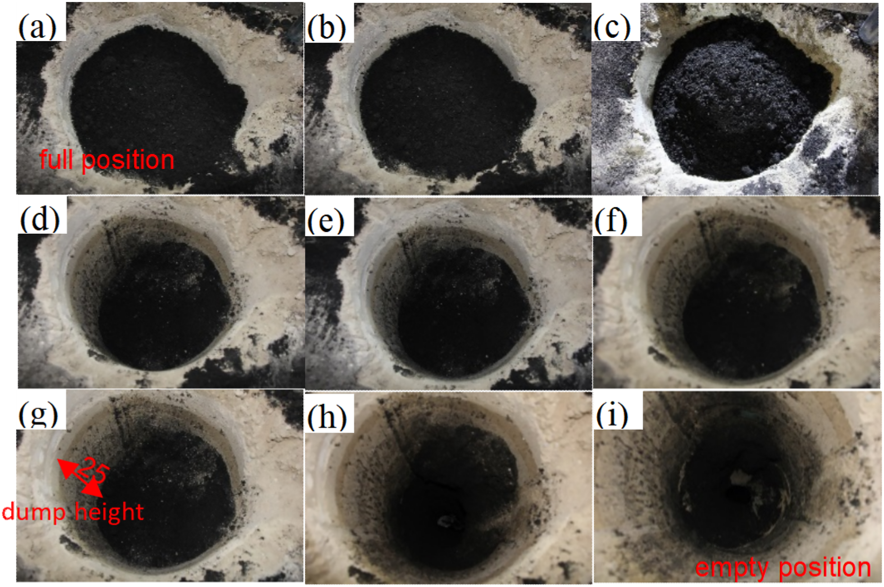
The funnel-shaped flow of the middle bulk particles. That is during unloading, only the bulk particles within a certain height range at the upper part of the unloading port flow in a funnel-shaped way. And the materials will be “last in first out”, which is easy to arch and bond, which greatly reduces the effective storage capacity of the shaft coal pocket. The funnel-shaped flow is shown in Figure 7, and it also reflects the whole process of funnel-shaped flow obtained from coal drawing experiment.
Coal caving funnel flow (second experiment).
Tubular flow in the central region
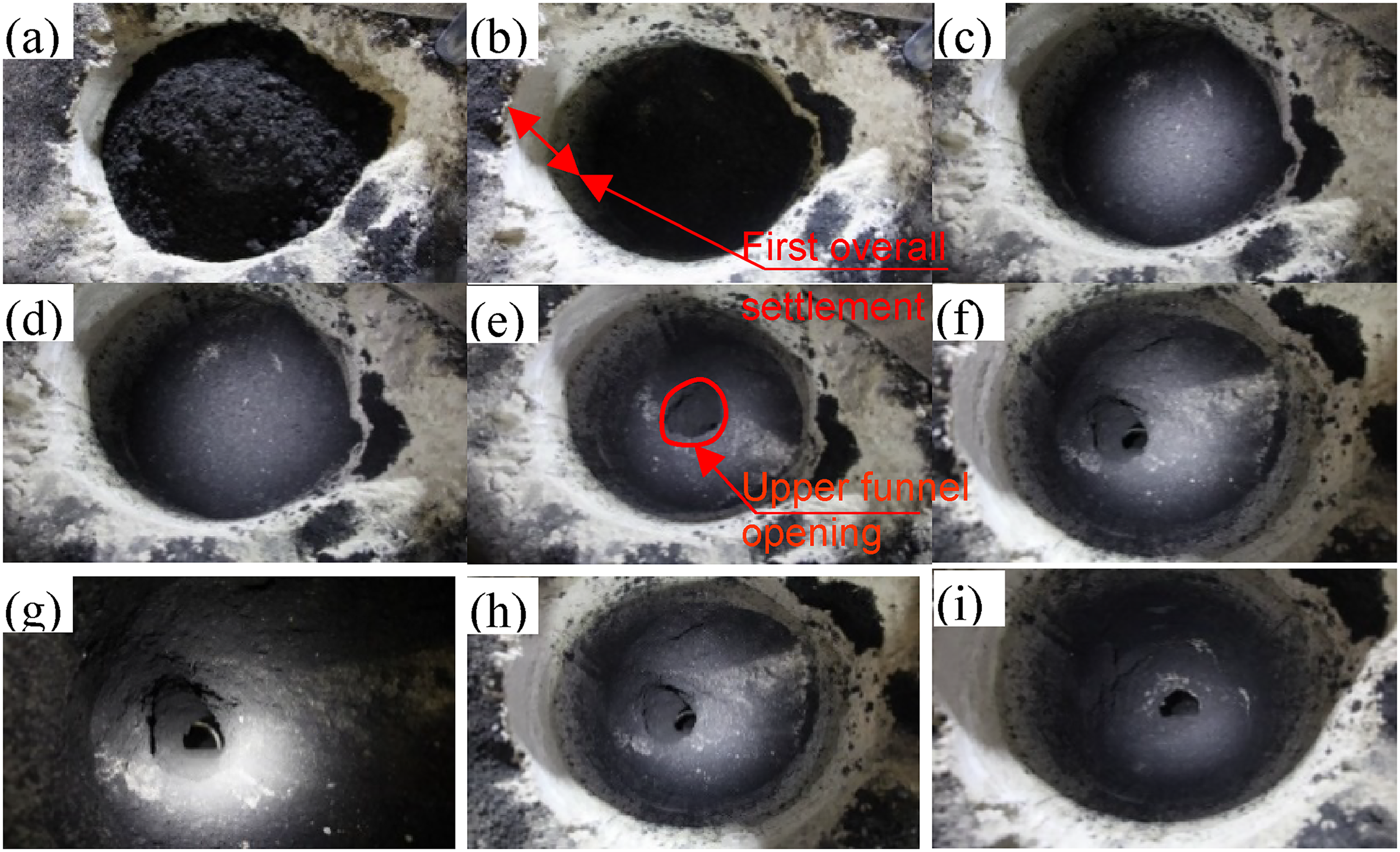
For the tubular flow in the central area, the loose particles in the bin form a flow channel in a narrow space at the upper part of the discharge port. While the storage near the bin wall remains stationary. At this time, the storage pressure of the shaft wall is close to the static pressure value. Figure 8 shows the whole process of tube flow and coal caving flow in the experiment, in which: c) is the first sudden subsidence, and g) is the occurrence of eccentric unloading after structural instability.
Coal caving tubular flow.
Particle spreading flow
With the expansion of particles, the stored materials flowing at the bottom of the shaft coal pocket form a steep funnel. The bulk particles in the funnel done whole flow. The upper part also enters the overall flow through diffusion, which is easy to form the most obvious “three-dimensional conical shell” structure inside the bodies, and the conical shell shape is relatively regular.
In the physical simulation experiment, the flow axis of bulk particles in the bunker during coal caving does not necessarily coincide with the vertical axis. After the bunker wall is used for a period of time, or to the dredging and clearing of the lower bunker after arching. Sometimes the flow axis has a certain included angle with the vertical axis, which may be related to the non-uniformity of bulk particles and the asymmetry of internal friction coefficient. In the process of sand discharge experiment, deflection angle is measured smaller or even negligible. Which is mainly due to the good flow characteristics of dry sand, and it is not easy to arch.
Division of vertical “three zones” of loose particles in shaft coal pocket
Division of “three zones” and flow characteristics of each zone: The flow trend of bulk particles in the shaft coal pocket is mainly affected by the particle size and physical properties. Such as the internal friction angle, cohesion, particle bulk density, and the friction coefficient between the wall and particles. It is found that the natural repose angle of bulk particles affects the overall flow characteristics by affecting the shape of the upper cone in the bunker after loading.
In the unloading process of shaft coal pocket, when the loose particles are ideal particles and the particle fluidity is particularly good during discharging. In principle, the lower particles flow out first after the lower unloading port is opened. When the particles are supported by the internal structure, there will be short-term arching. Part of the coal above the structure is supported by the lower supporting structure and compressed by the accumulated coal particles on the upper part. So a compaction area is formed. The natural accumulation area is from the upper part of the compaction area to the accumulation free surface.
When the internal bearing structure is unstable, the upper particles gradually supplement and fill the formed space, the particles in the middle area of the warehouse collapse first (the shell shoulder is unstable). Then the particles return to flow. The process of continuously discharging coal into the lower part of the hopper is repeated until all the coal is discharged into the lower part of the shaft coal pocket.
Through further analysis, it is found that the above trend is only in the ideal state, which is difficult to be measured in the actual experiment. This trend is divided into three sections vertically according to the internal structure. Combined with the physical experiment and the formation of the bulk structure in the silo, the detailed flow trend of each spatial area is fully analyzed. Through the experimental study of the flow trend of the stored material, it is found that the bulk particles can be divided into “three areas” longitudinally in the shaft coal pocket according to the fluidity, As shown in Figure 9.
Combined with the process of several similar simulation tests, it is found that the sequence of loose particles flowing out of the coal bunker in each area is as follows: natural flow area in the lower part of the conical shell structure A — compaction area overlying the three-dimensional conical shell B — overall flow area at the top C.
Dispersion flow trend in each area: The areas that are easy to form bulk particle bearing structure are mainly concentrated in the middle and lower part of the shaft coal pocket, and the intersection area between the lower funnel outlet and the straight wall. For the upper area, the flow trend is: stagnant flow at the beginning of coal caving — sudden and rapid flow as a whole — deceleration of overall flow in the upper part — Secondary stagnant flow in the upper part (if arching) — until the particles near the upper bin wall completely flow out.
The characteristics of each area in the “three areas” are briefly described as follows: the natural flow area A in the lower part of the structure is located at the intersection of the funnel and the straight wall. This area is often the shell base of the three-dimensional conical shell structure in the warehouse and its lower area. Under the bearing function of the structure, it is often retained by the support of the lower funnel wall and the extrusion of the middle loose body. The friction of the warehouse wall and the inclined support of the funnel can't be ignored. If the loose coal in this area wants to flow out, The maximum horizontal displacement is required, and the coal is most likely to be blocked in this area. This area is also the area that flows out of the bunker first when the lower gate is opened; Area B is the compacted area overlying the structure, and the mechanical bearing structure of three-dimensional moving balance conical shell is easy to appear in the lower part of this area. Area C is the overall flow area of the top surface of the storage material. This area shows that the bulk particles with a certain thickness slide down as a whole frequently, which has also been observed many times in the experiment. Sometimes the instantaneous sliding distance is very large, which can reach about 20% of the height of the shaft coal pocket wall.
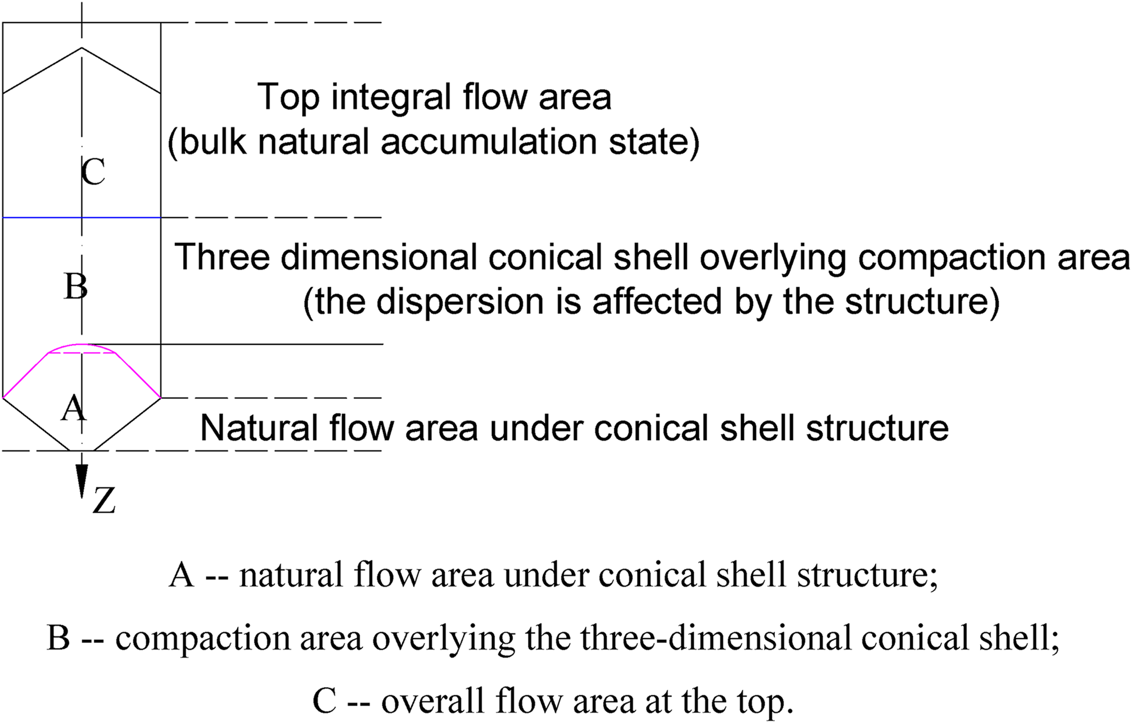
“Three zones” of loose particles in shaft coal pocket according to fluidity.
According to the experimental measurement, the bulk particles with considerable thickness in the upper C area do not participate in the movement at the initial stage of unloading. They slip after the first instantaneous overall flow. After experience the cycle of accelerated sliding, decelerated sliding and secondary stability. In essence, after the lower particles are released, the newly flowing particles form a three-dimensional bearing structure and support them until they are secondary stable. Figure 10 shows the measurement of the falling height after the first sliding in the C area. During the first coal unloading, the overall sliding height of the upper opening reaches 22cm, and the unloading overpressure is very obvious.
Measurement of slip height after the first instantaneous overall flow in upper region.
“two circles” distribution characteristics of loose particles in shaft coal pocket
As a whole, the loose particles in the shaft coal pocket is characterized by “two circles”. Which is close to the axis area, the lower the area, the better the fluidity, and the lower the area close to the bunker wall, the worse the fluidity.
The flow trend of some particles in the middle is as follows: the particles in the smooth passage in the central area of the middle flow out first. After flowing out, the particles in this area will be filled by the particles in the upper area, then flow out, and then the loose particles in the outer area of the middle flow out.
The particle flow trend in the natural flow area under the bearing structure is as follows: the loose particles in the funnel under the structure flow out according to the natural regular pattern. Due to the protection of its upper conical shell structure, the loose particles in this area are less under the upper pressure, which have random natural outflow trend after coal caving.
When the flow velocity near the silo wall slows down to a certain extent, retention often occurs. At this time, coal particles will hang on the outer coal wall, as shown in Figure 11.
Wall hanging of coal (sand) particles.
Numerical experimental analysis of the flow trend of particles
Particle flow when the shaft coal pocket is full
Information about the numerical simulation: use the fish language embedded in PFC3D to write model data, use the spherical element to approximate simulate the granular coal particles, and use the wall element to simulate the shaft coal pocket wall. The total height of the particle pile simulated in the experiment is 20 m. The whole particle pile is divided into six layers with different colors, and each layer has the same thickness. The ball porosity is 0.3, and the contact model is the line contact model. The particle radius is 0.04∼0.08 m, the particles are uniformly distributed, and the number of particles generated by the final model is 53624.
The movement law of the loose particles in the shaft coal pocket when the bunker is full is analyzed by using the particle flow numerical software PFC3D. The flow of the loose particles in the normal state when the bunker is full is shown in Figure 12:
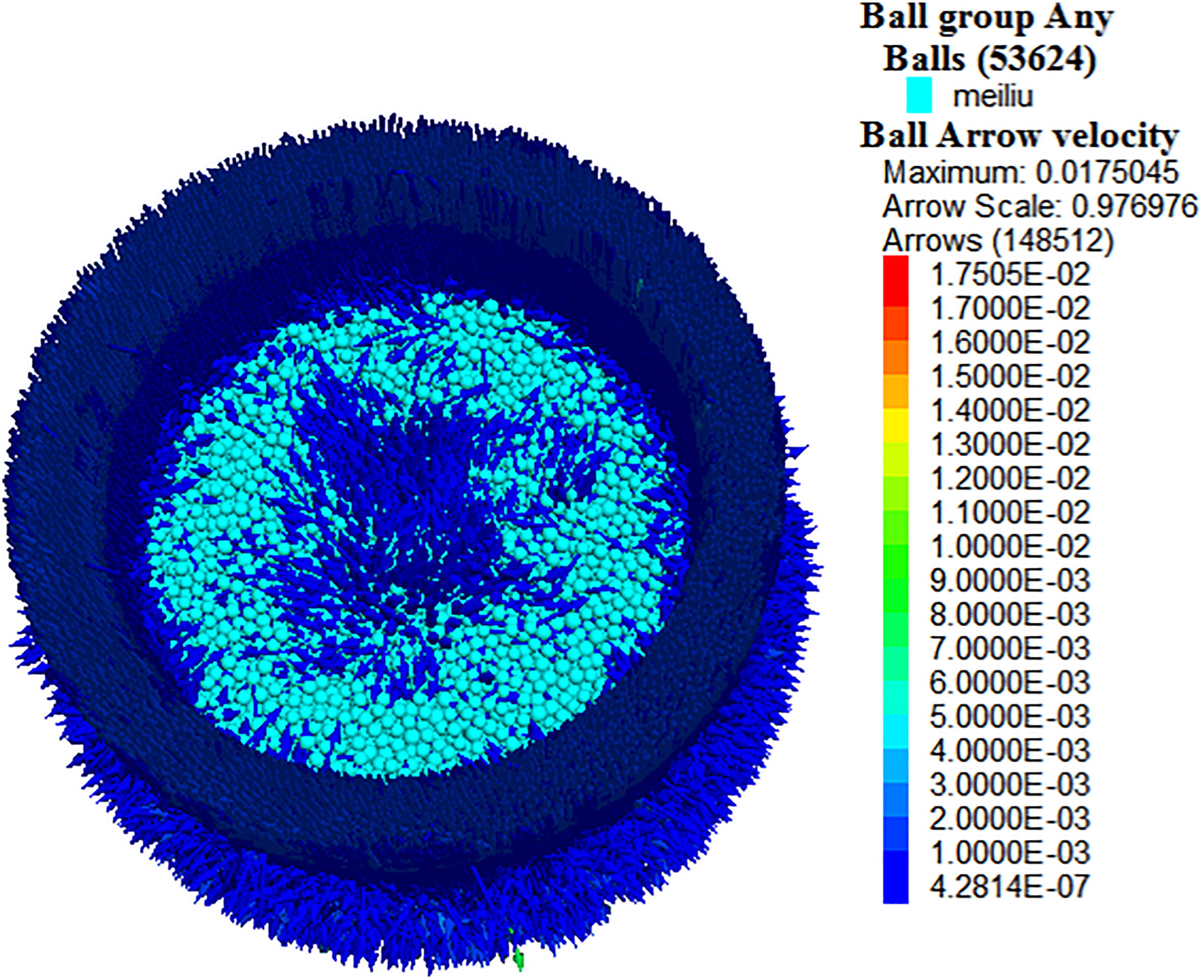
Movement of coal particles in full.
Figure 12 shows that during normal coal drawing, the loose particles in the bunker move to the center. The flow speed of coal particles in the central area is greater than the particles near the shaft coal pocket wall.
Particle flow when the shaft coal pocket storing location is half
The shaft coal pocket has another work state which is half store location. At this time, the upper entrance of the coal bunker is loading coal and the lower opening is also discharging coal. This work state between full bunker and empty bunker. In this state, the area above the coal loading height equivalent to empty, and the area below the coal loading height equivalent to full. And it also impacted by the coal flow. The lower area in this state was frequent loading and unloading, so the deformation of the shaft wall is mainly concentrated in the middle and lower area. Some elastic deformation increases with the increase of side pressure, and recovers with the decrease of side pressure.
Figure 13 shows when half of the materials are stored in the shaft coal pocket, and the coal is discharged. Figure 13 also shows that the situation of half bin is equivalent to the combination of empty bin at the upper part and full bin at the lower part of the shaft coal pocket. It can be seen that the coal particles on the upper surface of the coal loading area are free surfaces, where the load of internal particles on the bin wall is zero. The particles movement characteristics from the top to the bottom of the bin are basically in line with the full bin, but the height of the coal bunker at this time is equivalent to the height of the shaft wall.
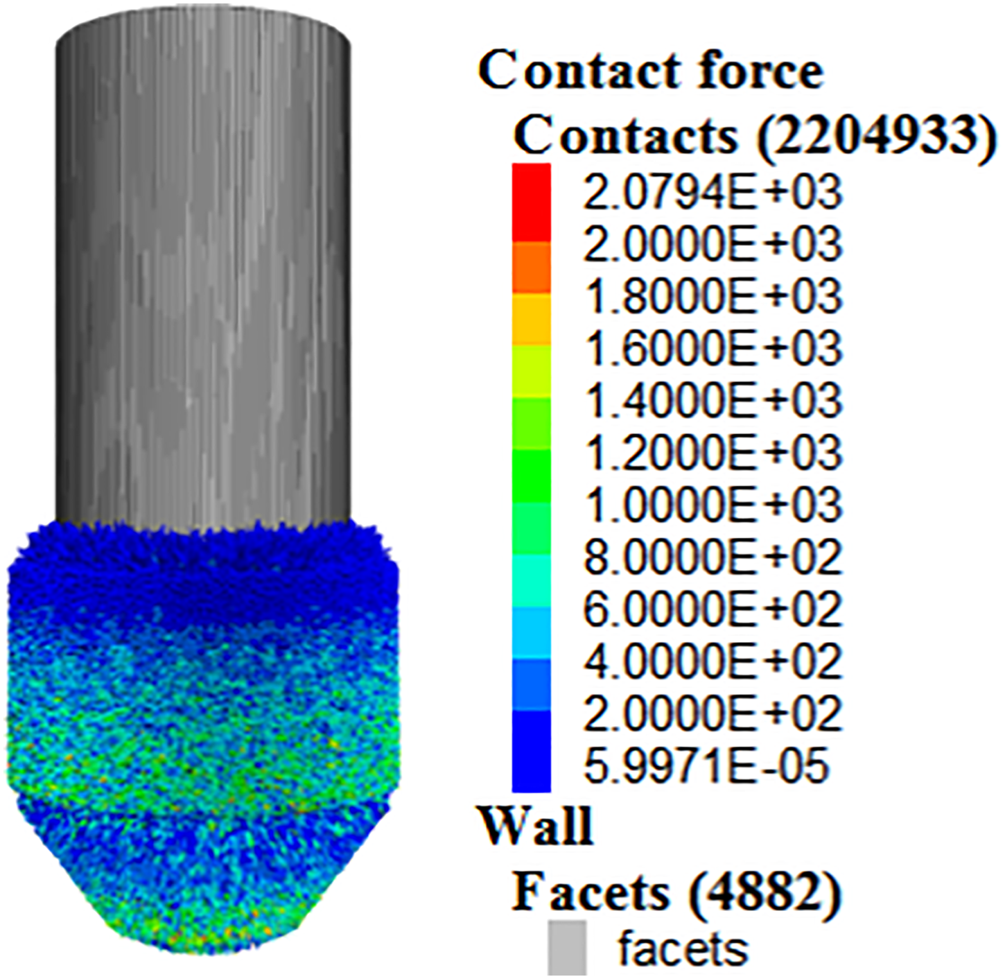
Force chain diagram of shaft coal pocket wall in half.
Conclusions
Through the three-dimensional physical experiment, the movement trend of loose particles in the shaft coal pocket can be well simulated. The flow forms in the bunker can be divided into whole flow, tubular flow and funnel flow.
The division of vertical “three zones” and horizontal “two circles” is given. It is found that the sequence of loose particles flow out of the coal bunker in each area is as follows: natural flow area at the lower part of the conical shell structure A — compaction area overlie the three-dimensional conical shell B — overall flow area at the top C. The transverse flow trend of the loose particles in the bunker is shows the “two circle” characteristics of being close to the axis area, the lower the area, the better the fluidity, and the lower the area close to the bunker wall, the worse the fluidity.
The flow trend of some particles in the middle is as follows: the particles in the smooth passage in the central area of the middle flow out first. Then the particles in this area will be filled by the particles in the upper area, later outflow. Then the loose particles in the outer area of the middle flow out. The particle flow trend in the natural flow area under the bearing structure is as follows: the loose particles in the funnel under the structure flow out according to the natural law. Due to the protection of its upper conical shell structure, the loose particles pressure in under area are less than the upper. After coal discharge, the particles show random natural outflow.
Through numerical experiments, it is found that the flow trend of particles in the full or half bunker is different. When it is full, the lower part flows naturally and the upper part flows as a whole; When it is half, the situation of half bunker is equivalent to the combination of empty at the upper part, and full bunker at the lower part. The coal particles on the upper surface of the coal loading area are free surfaces, where the load of internal particles on the wall is zero. The movement from the top to the bottom basically conforms to the motion characteristics of full bunker, but the effective height of the shaft coal pocket at this time is equivalent to coal location height.
Footnotes
Acknowledges
The authors would like to acknowledge the financial supports from the National Natural Science Foundation of PRC (51634007); Major Scientific and Technological Innovation project of Shandong Province (2019JZZY020326); Shaanxi Natural Science Basic Research Plan Shaanxi Coal Joint Fund project (2021JLM-10); Shanxi Institute of Energy Project (ZY-2018009).
Declaration of conflicting interests
The author(s) declared no potential conflicts of interest with respect to the research, authorship, and/or publication of this article.
Funding
The author(s) disclosed receipt of the following financial support for the research, authorship, and/or publication of this article: This work was supported by the Major Scientific and Technological Innovation Project of Shandong Province, Shaanxi Natural Science Basic Research Plan Shaanxi Coal Joint Fund project, National Natural Science Foundation of PRC, Shanxi Institute of Energy Projec, (grant number 2019JZZY020326, 2021JLM-10, 51634007, ZY-2018009).