
Abstract
The huge, inclined goaf formed by the mining of steeply inclined and extra thick coal seams has the characteristics of occupying a large space and being subject to complex breaking behavior of its overlying rock structure, especially the rock block structure characteristics of the interface area between the goaf and the lower working face which is difficult to be characterized, leading to a hidden danger when mining the lower working face. In response to the aforementioned problems, the following conclusions are drawing as follows: (1) with the aid of the contradiction method, the critical condition governing instability of the triangular articulated structure was obtained to explain the correctness of the assumption of the triangular hinged structure; (2) three-point truss structure was composed of key layer blocks; (3) in the stabilization stage of the triangular hinged structure, the fracture network area was extracted, and the centerline intensive equivalent method of a single fracture segment was adopted to directly measure the equivalent length. Meanwhile, the value of equivalent average width with the equivalent length of a single crack was calculated by integral operation and equivalent figure calculation; (4) the mathematical expressions of permeability which was positively exponential function related to the ratio of equivalent average width to equivalent length were derived. Furthermore, the vectorized solution of seepage rate was carried out respectively for the goaf area and the extracted network area by using COMSOL software. The distribution of the strong seepage area of CBM and the ratio of equivalent average width to equivalent length is found to be consistent to a large extent, which provides theoretical support for subsequent CBM management.
Keywords
Introduction
At present, the treatment of gas in goaf relies on drainage methods such as buried pipes and high-level drilling, however, in many cases, the treatment effect is not ideal due to the lack of systematic theoretical basis for the treatment system parameters (such as borehole spacing, detailed location of borehole intensive area, etc.). Furthermore, it is more difficult to control gas in the goaf of steeply inclined and extra-thick coal seams. Large scale, large deformation rate, severe damage, and negative societal impact are the four major characteristics for deformation and instability of the goaf in the steeply inclined coal seam. Besides, a large goaf is only temporary status; when there are external incentives (such as mining influences of other working faces, etc.), it may cause large-scale dynamic instability, which will evolve into a dynamic disaster(Cui et al., 2019; Wang et al., 2013; Wu et al., 2018).
Therefore, it is particularly necessary to study the caving and accumulation laws of coal and rock blocks in the goaf. Recently, theoretical research and numerical calculation are mainly used to study the evolution of overburden structures in the process of steep coal seam mining. Equivalent calculation of overburden structure was undertaken by using mechanical modeling, including beam and curved bar models in material mechanics.
After the mining of steeply inclined coal seams, the deformation of the lower end of the coal roof is very small due to the supporting effect of the falling gangue and the restraint afforded by the unexcavated coal body on the roof, so it can be considered to be a fixed support (Lai et al., 2015); the impact of broken rock masses, rock slippage, etc., can be considered to represent a simply supported state(Ju and Li, 2008); some scholars have investigated thin-plate models from elastic mechanics(Alzebdeh, 2012; Chen et al.,2005; Tu, 2014). In addition, different forms of arc-shaped structures have been proposed, Yan et al. (2015) explained that the deep partial mining caving zone of steeply inclined coal seams readily forms a trapezoidal arch structure; Shi and Zhang (2006) proposed that a spanning arch structure forms above the steeply inclined working face; Dai et al. (2013) proposed that stratal movement can be controlled by the stressed arch structure in the horizontal stratified mining of an extra-thick steeply inclined coal seam. Also, the mechanical calculation models combining an arch-beam and slab-beam have been studied, Qian (2020) took the roof of coal seam as the whole research object and treated it as a slab-beam structure. When the roof of a steeply inclined coal face has not caved for the first time, it was equivalent to a thin plate with four fixed sides. When the roof collapsed for the first time, it was equivalent to having three sides fixed and one side simply supported. Lai et al. (2020) stated that the arch-beam structure formed by a roof rock beam and overlying rock arch in steeply inclined coal seam mining had the characteristics of spatial structure correlation.
In conclusion, these studies focus on the upper part of the steeply inclined goaf, while there is a lack of research on the middle and lower areas of the extremely inclined goaf. Also, with reference to the analysis of fracture field similarity simulation experiment results of steeply inclined coal seam sub-level mining (Liu, 2018), When the working face mining distance was short, the mechanical structure of beam was established in the extremely inclined goaf along the inclination direction of the working face, making it easier to form a transient state (Gao, 2014).
Regarding the transient state manifest in the aforementioned goaf, few researchers have investigated the issue, especially in terms of judgment of the stability of the local special structural zone, and the dynamic changes of key parameters affecting the extraction of coalbed methane around the structural area, such as permeability, etc.
If the permeability parameters change, how to quantify the permeability around the local special structural zone in that transient state? In this paper we present detailed analysis and a solution to this problem.
Instability analysis for bottom part of inclined goaf
Evolution of triangle articulated structure
It is well known that the structure of key strata plays an important role in the morphology evolution of goaf. So in this section, we will focus on analyzing the effect of structural changes for key layers on the stability of the bottom structure in the goaf.
Based on this, the morphologic evolution chart for the goaf along the inclination of working face was plotted. As shown in Figure 1(a), almost all the direct roof of the working face was subject to caving, with partial caving of the main roof, as a result, a parabolic section named elliptical parabolic band with a fracture structure was formed, in which the transverse layer separation fissure and longitudinal fracture fissure were developed, and the pressure relief gas could migrate and accumulate actively (Ding et al., 2021; Li et al., 2014). However, due to the collapsed blocks being small and few in number, it was difficult to form an obvious block-block articulated structure, but more cinder and direct roof scattered bodies appeared in the bottom of the goaf (Figure 1(b)) that the lower coal working face entered the next section for mining, and the overlying strata collapsed until the sub-critical layer 2 (Qian et al., 2000), which did not collapse due to the supporting effect thereof on the upper overlying structure. However, the rock below the sub-critical layer 2 has collapsed sufficiently, and a two-layer block-block hinged structure was formed inside the goaf; as shown in Figure 1(c) the structure of the overlying strata continued to collapse to sub-critical layer 1. At this time, four layers of obvious block-block hinged structures were formed in the goaf. When the overlying rock structure collapsed to the sub-critical layer 2 and sub-critical layer 1, the overlying rock structure was unstable and damaged, the block structure gradually rotated, flexed, and sank: the block-to-block hinged structure gradually expanded, and the bottom of the hinged area due to the upper part of extrusion appeared to be “cracked-broken-slip-squeeze hinged”. The hinged structure was relatively stable and formed a three-point truss structure without being affected by the mining of the lower coal body; then, the overlying rock structure collapsed to the main key layer, and a relatively complete masonry beam structure was formed in the middle and lower parts of the goaf, as shown in Figure 1(d).
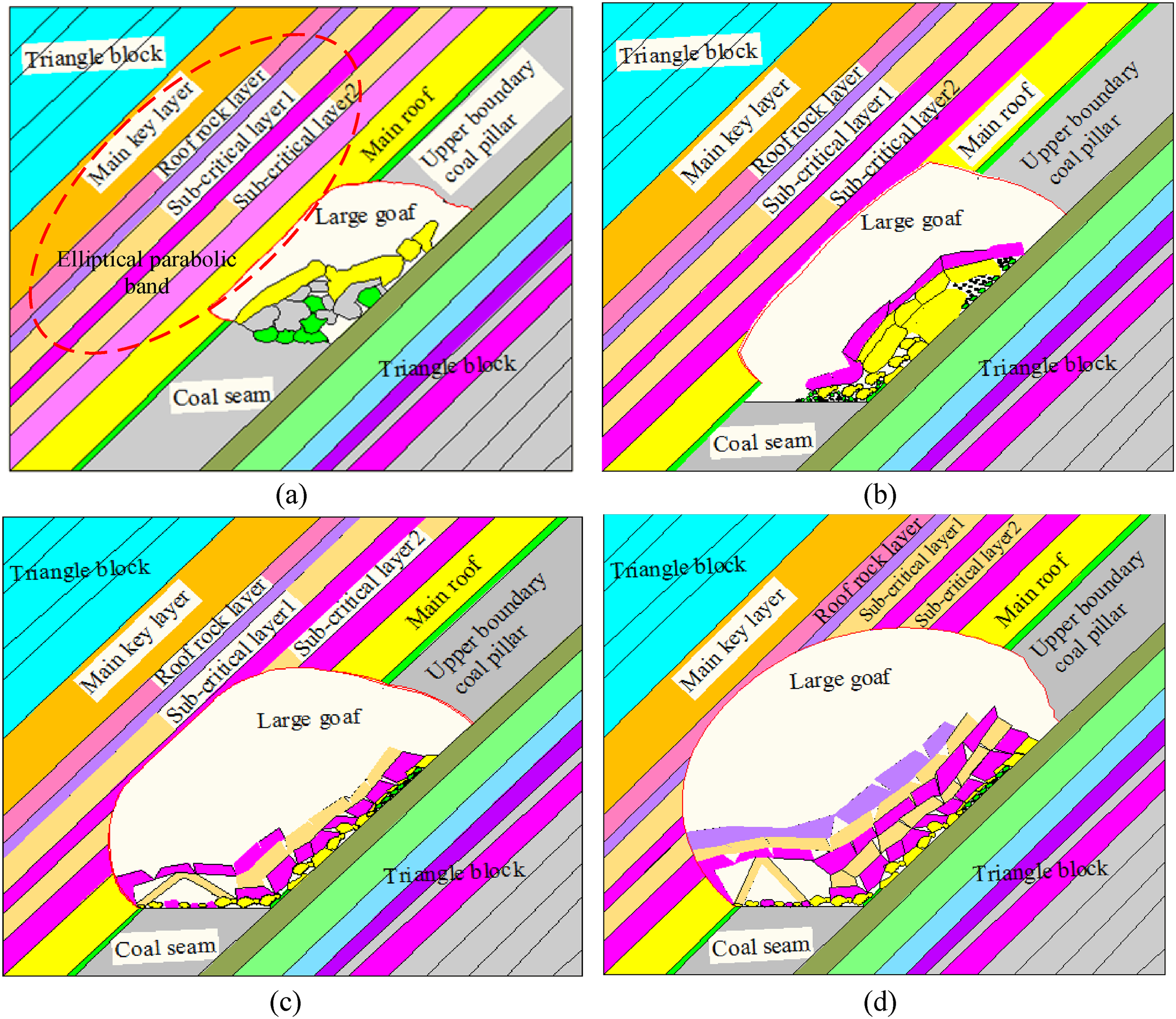
Evolution of goaf morphology: (a) basic roof collapsed and filled the goaf; (b) rock layer collapsed to sub-critical layer 2; (c) overburden caved to sub-critical layer 1 and (d) overlying rock layer collapsed to main key layer.
Then, Figure 2 shows the evolution and formation process of the triangular articulated structure with reference to the analysis Figure 1(c). Taking sub-critical level 2 as an example, the analysis relies on the contradiction method, that is to say, assuming that the triangular articulated structure conforms to the rod model, if the relevant mechanical solution can be obtained, the hypothesis is proved to be correct. When the overburden caves to sub-critical level 2, one end is narrow crack 1 and the other end is wide crack 1, this moment, the mechanical model is deemed to have one end hinged and the other free. The uniform load of the rod shaft subjected to the extrusion of upper coal and rock is q, and the axial load on the rod is G. Under the action of uniformly distributed load q and shaft load G, the shaft rotates clockwise, and the free end makes contact with the coal and gangue in the lower part of the goaf and becomes an articulated end, while the articulated end-point O breaks off into a free end and contacts the upper left boundary of the goaf, and the forces on both ends are F1 and F2 respectively. At this time, kinetic energy due to the high-speed rotation of the shaft and the collision with coal and gangue in the goaf generates wide cracks within the block, while the left segment gradually slips along the left arc boundary of the goaf under the action of gravity G1: finally the hinge joint of the left and right sections is formed that hinge point is B, of which the length of the left segment is L2 and the length of the right segment is L3, and the forces generated by the lower hinge points of the left and right sections are F3 and F4. With the further mining of the working face, the upper exposed rock layer of sub-critical level 1 further collapses, contacting point B to form the three-point crimping hinged structure. The forces on the left and right segments on the bottom hinged points are then F5 and F6.
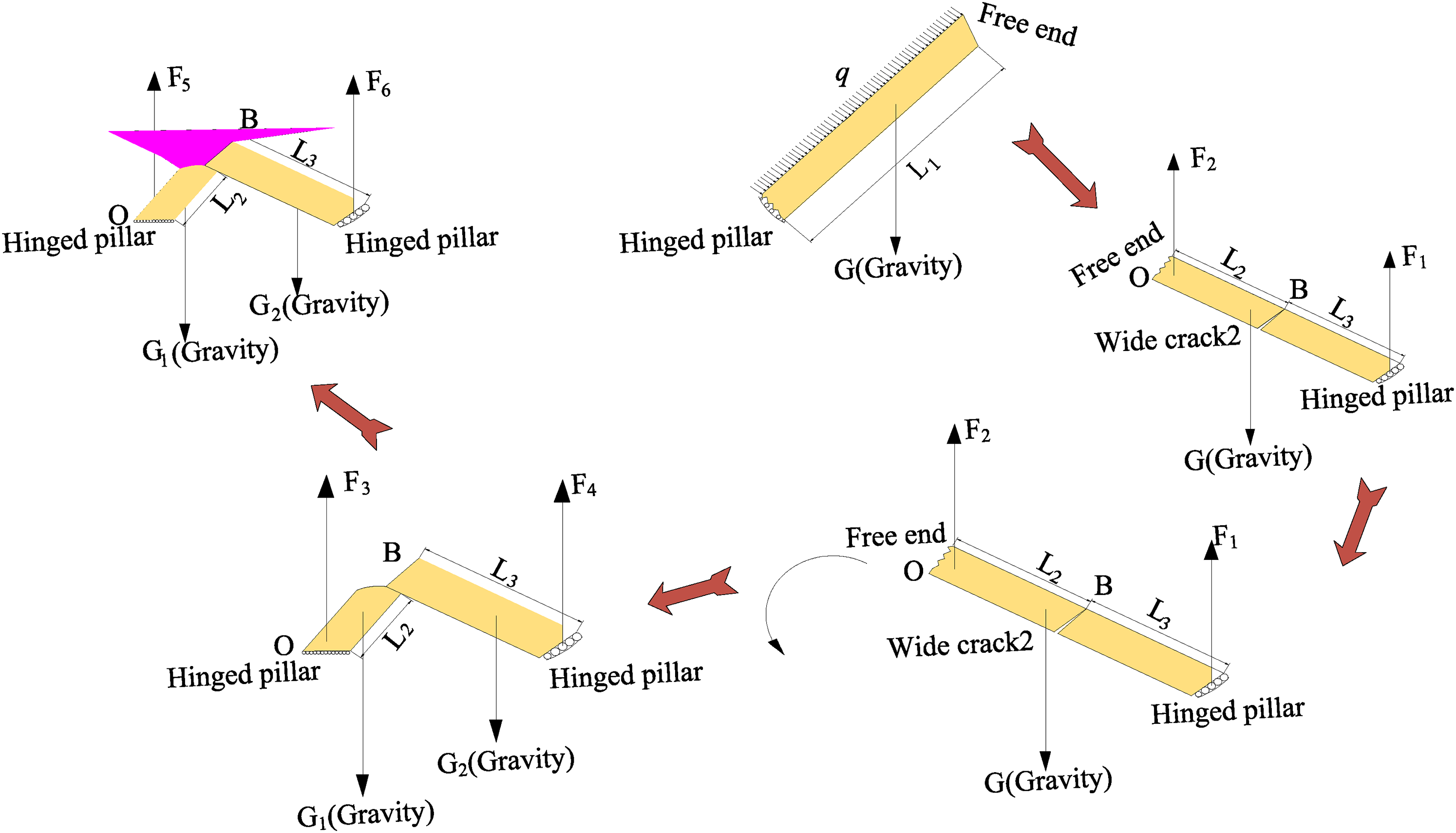
Schematic diagram for the evolution of the triangular hinged structure.
The three-point truss structure which was composed of key layer blocks exerted a great influence on the mining of the working face of the lower coal body. On the one hand, the three-point truss structure readily formed a closed chamber, in which gas accumulated. On the other hand, the masonry beam structure continued to sink due to the mining disturbance caused by the mining of the lower coal body and the expansion of the goaf volume, which will compress the gas originating from that closed chamber and force it downwards to the working face of the lower section, resulting in a large increase in the probability of local gas exceeding acceptable limits during mining of the working face (Li et al., 2021; Lin, 2004; Xia et al., 2017).
Mechanical calculation model
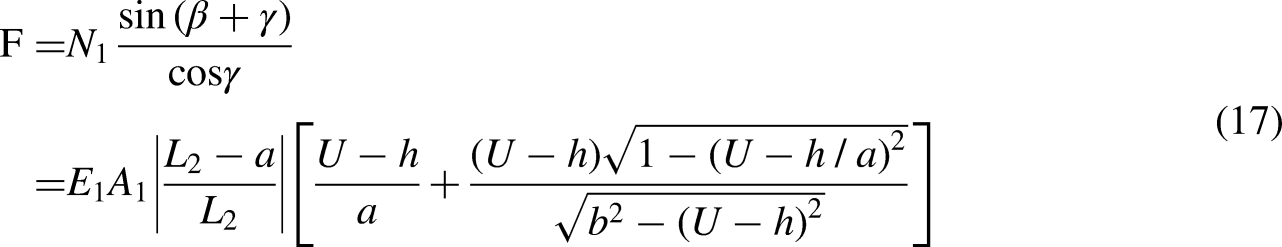
Combined with the schematic diagram of the evolution process of the triangular hinge structure shown in Figure 2 and mechanical model of triangular hinged structure shown in Figure 3, the following mechanical expressions were established:


Mechanical model of triangular hinged structure.
According to equations (1) and (2):


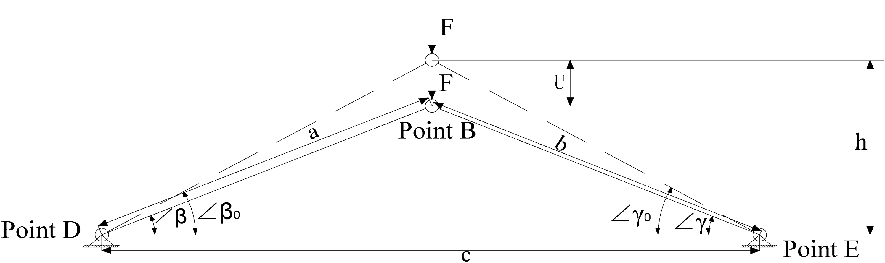
The initial lengths of the hinged triangular structure are L2 and L3, and the downward displacement U occurs under the action of F, and the vertical distance between the hinged point B and the lower two hinged points is h. Based on the above parameters, the geometric expression was established as follows:


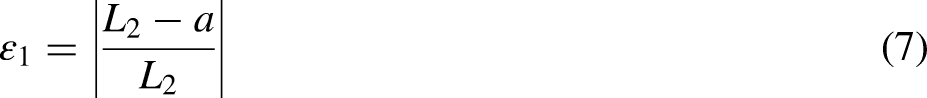
The equation of strain expression for lengths L2 and L3 at both ends of the triangular hinged structure was established as follows:
According to Hooke's theorem, the relationship between stress and strain was established as follows:


As shown in Figure 4, the calculation model of triangular hinged structure took the initial hinged point B as the origin of coordinates. The downward Y-axis and the horizontal right X-axis were established, and the vertical displacement U of point B was described as follows:

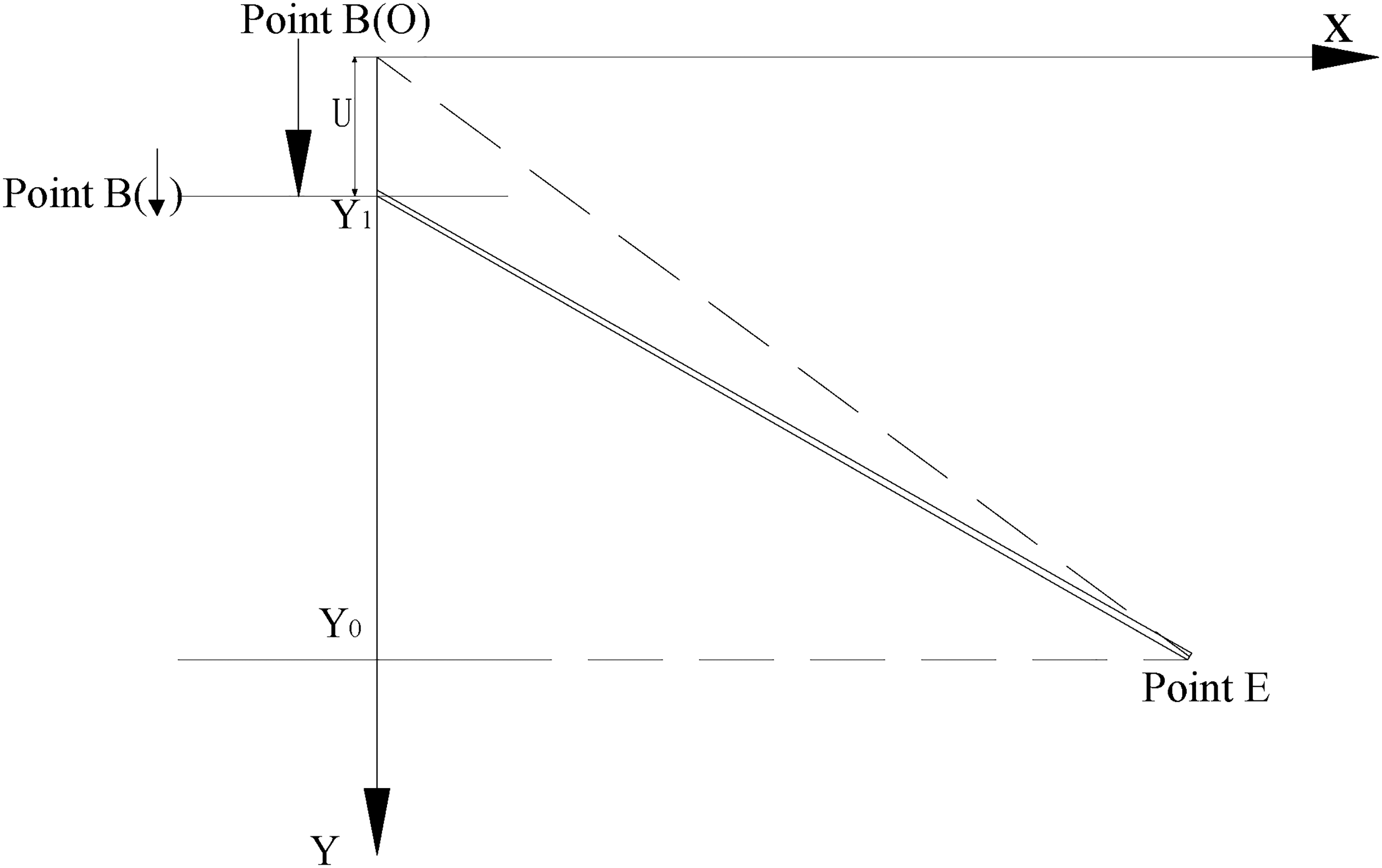
Coordinate calculation model of triangular hinge structure.
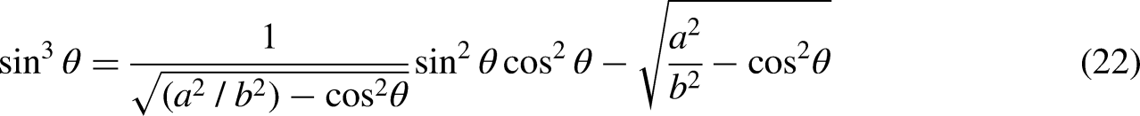
Only considering β to establish the expression, the following expression could be obtained by gradual transformation according to equation (11):


Equation (18) was simplified by means of substitution of trigonometric functions:


Permeability variation in the surrounding rock as affected by the triangular structure
To ascertain the distribution of the permeability of the goaf, by referring to a large number of previous results, permeability was related to the extension direction, width, number, and density of coal and rock fractures, and the degree of development of fractures. However, the methods to solve the permeability mainly include the establishment of coal stress-porosity-permeability relationship analysis method, CT scanning method, etc. (Brambilla et al., 2021), such as coal-rock stress and relationship between porosity and permeability analysis based on in-situ stress distribution, and the stress and permeability relationship. This method was commonly used in numerical simulations, and calculation formulae using third-party software (such as MATLAB™, inter alia) to solve the problem; solutions are often cumbersome and the error therein is high, while the CT scanning method needs to be matched with hardware facilities, leading to increased costs.
Therefore, the permeability of coal in goaf along the direction of inclination of the working face was evaluated, and the influence of the crack width needed to be considered. The main problems that need to be explored and solved were: on the one hand, to quantify the change in the permeability of the triangular hinged structure formed by the breaking of the key layer to the position between the goaf and triangular hinge structure formed by breaking of key layer; the other was to derive a method for solving the crack width. A method reliant on the processing of mining-induced fissure image threshold was proposed, and third-party software (such as CAD, inter alia) was used in extraction processing for fissure mapping. Finally, mathematical equivalent calculation methods were adopted to calculate the average width of fissured units.
Identification of fracture zones
With reference to the morphological evolution of goaf in Figure 1(d) and the analysis of similar simulation experimental results of fracture field in segmental mining of steeply inclined coal seams (Liu, 2018), the picture was imported into image processing software. Finally, images of easily differentiated rock blocks and fracture zones were formed, as shown in Figure 5.
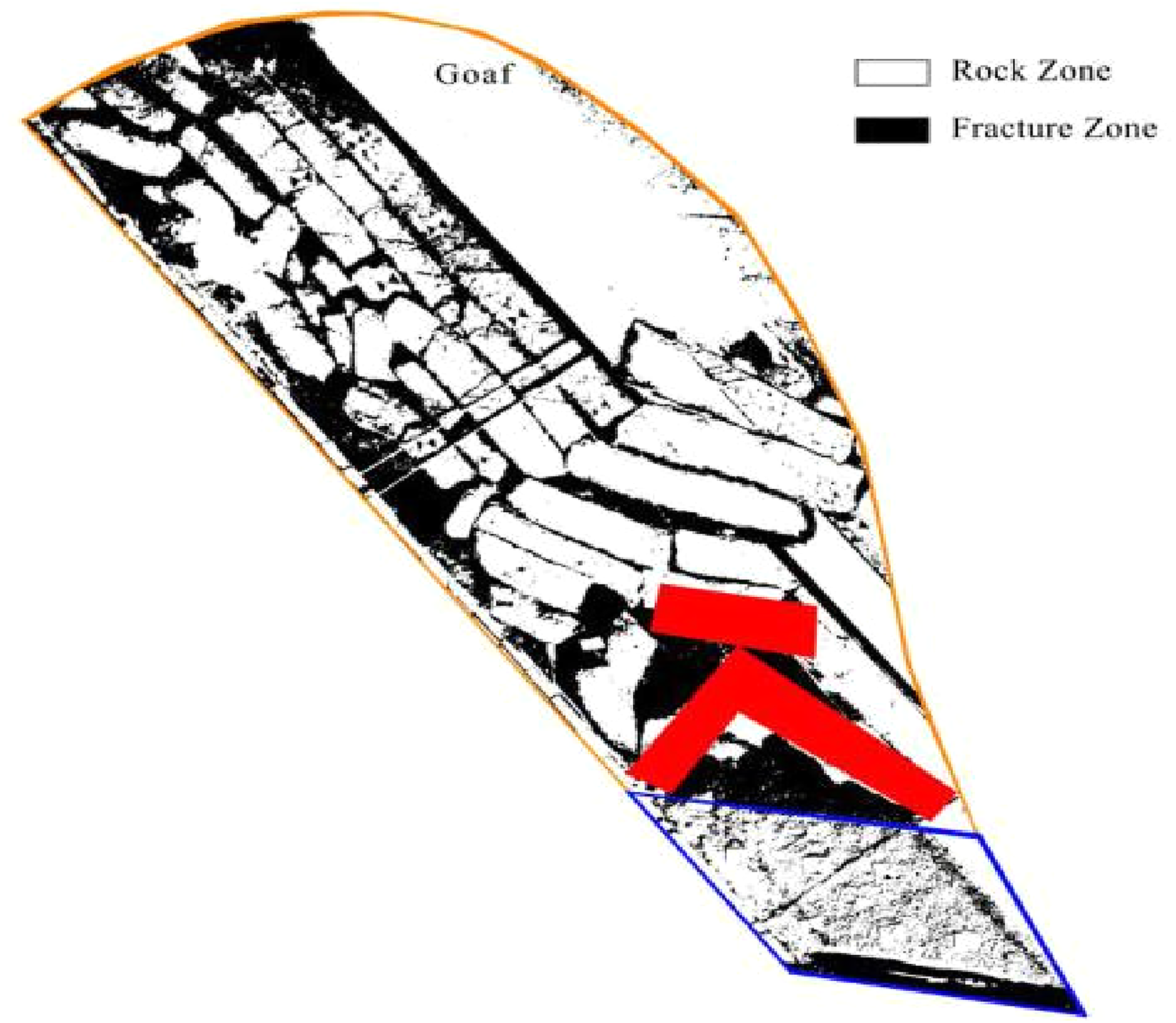
Analysis of coal-rock fractures (Liu 2018).
Extract coal and rock fissure area
After the coal and rock fracture produced under the influence of mining passed through the binarization treatment method of Figure 5, the graphical element level became distinct, and also the black was the fracture region. At the same time, the differential set analysis method was performed, as shown in Figure 6, setting the gob area for collection P1, block stacking area for collection P2, coal and rock fracture zone for aggregate P3, gap area of upper goaf as the aggregation P4, then p1 = p2∪p3∪p4, and the fracture channel P3 region between the fractured of rock blocks was extracted, as shown in Figure 7.
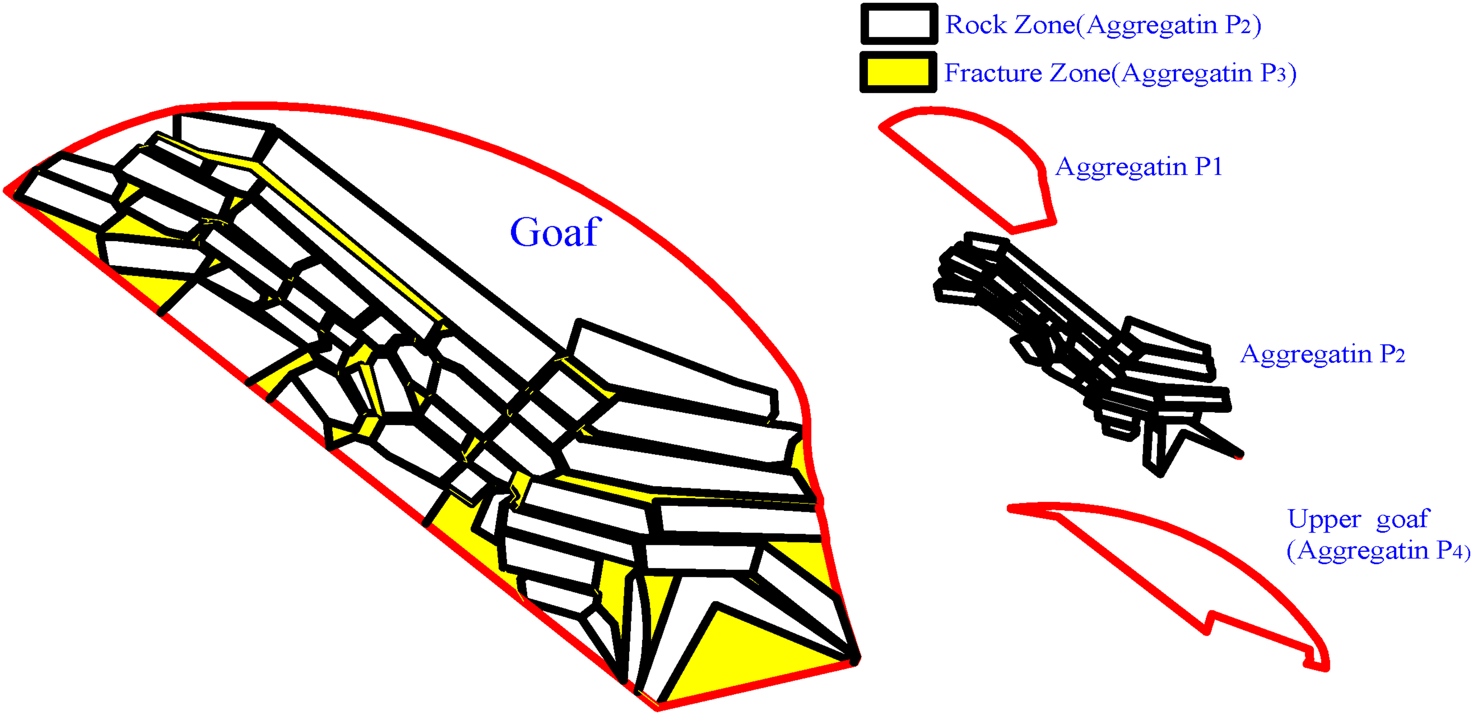
Classification and extraction of coal-rock fracture zone.
Network channels in coal-rock fractured zone.
According to Figure 8, the fracture network area of broken rock block was extracted, and the nodes of the network area were set as A, B, C, D, E and F. Combined with the method for roadway heading along the center-line of floor, dense vertical segments with equal distance were made along the width of the fracture network, and then the midpoint of the segments was captured to form the center-line, which was the basis for solving the fracture length, effective length L of the fracture could be measured directly.
Equivalent schematic diagram for the length of the fracture network.
Calculation of equivalent average width of the fracture zone
As shown in Figure 5, the red area is a triangular hinged structure, and the calculation of the average width of the coal-rock fissure area is more complicated. For this reason, the fissure area between the blocks was cut and combined to form a familiar shape. For this reason, as shown in Figure 6, the equivalent calculation method was adopted, and the shapes were divided into closed zone and unclosed zone. The equivalent shapes of the closed zone included: trapezoid, triangle, and ellipse; while the unclosed zone included an elliptical arc, a circular arc, and a trapezoid combined with an elliptical arc.
Among them, the most complex trapezoid and elliptical arc mixed-shape calculation was taken as an example to calculate the average width. Then, the same equivalent calculation method was used to find the average width of the trapezoid, triangle, ellipse, and arc region by analogy (Figure 9).
Calculation model for the combined trapezoid and elliptical arc region.
Assuming the elliptical arc satisfied equation (26), the area of the non-closed region in Figure 9 was solved by decomposition method, and the area of the non-closed region in Figure 9 was equivalent to the sum of the area of the trapezoid and the area of the elliptical arcs on both sides. However, taking the area of the left-hand elliptical arc as an example, using integral method, the area of the non-closed region SM in Figure 9 was expressed as follows:


Borden_width's formulas for cracks of different shapes.
The expression of coal reservoir permeability K and effective stress σF was as follows (Wang et al., 2015):


Case study
Solving the instability condition of the triangular hinged structure
Taking the 45# coal seam with as the research object (Liu, 2018), sub-critical layer 2 was a hard rock layer with siltstone as its lithology, which was separated by three intermediate layers from the 45# coal seam. According to the corresponding data from the literature, it was calculated by substituting into Formula (25) to obtain: Smax = 5.290 m. Results showed that the triangular hinged structure that was formed by sub-critical layer 2 mining within 5.290 m along the strike direction of working face was stable.
Solving value of permeability K
According to the method of calculating the permeability of the fracture network which elaborated that the permeability change law of surrounding rock blocks affected by the triangular structure, in order to facilitate the analysis, it is known that the air permeability coefficient λ of the coal seam is 0.009∼0.871 m2/MPa2·d and the permeability of the coal seam was further converted into 2.280 × 10⁻¹⁹∼2.206 × 10⁻¹⁷ m2 and the average value was obtained: K0 = 1.16 × 10⁻¹⁷ m2 and the effective stress σF = 5.625 MPa.
Aiming at the value of the rock compression coefficient d in formula (33) (Li et al. 2019) when the water content of the coal seam was 2% d = −2.14273 × 10⁻² Pa−2 and formula (23) was further simplified to obtain formula (34). At the same time the comparison of fracture network permeability was simplified to the size of Borden_width/L and finally the value of Borden_width/L was marked on the fracture network diagram as shown in Figure 10.
Distribution law of borden_width/L value.
Simulating seepage rate
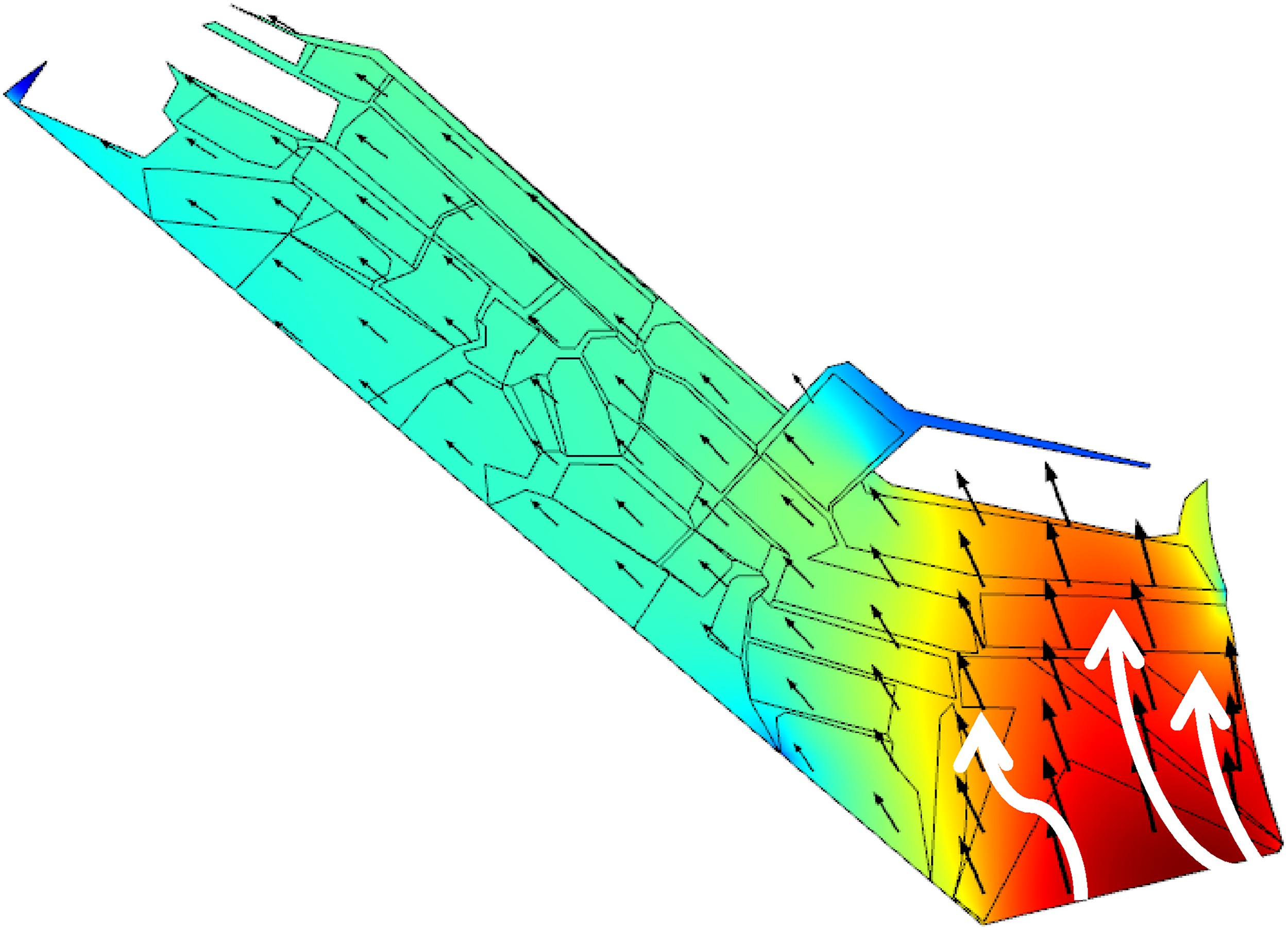
Taking the 45# coal seam as the research object (Liu 2018) the analysis model was established with the help of Comsol numerical software as shown in Figure 11. The size of the model was 15 × 3.6 m the calculation model was in keeping with the arched goaf and the meshing of the model was shown in Figure 12 which displayed the mesh density of the fracture network area was greater than that of the other areas. For boundary conditions the bottom section AB was set as the normal mass source entrance the mass source Q = 5E − 5 (kg/s) and the remaining boundaries were set to suppress backflow. Finally the seepage rate vector diagram of the fracture network was obtained as shown in Figure 13.
Schematic diagram of numerical calculation model.
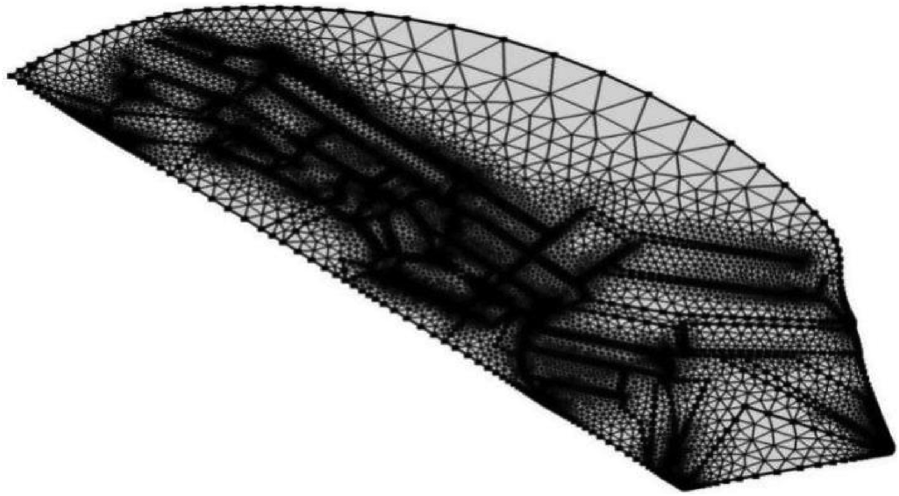
Schematic diagram of model grid partition.
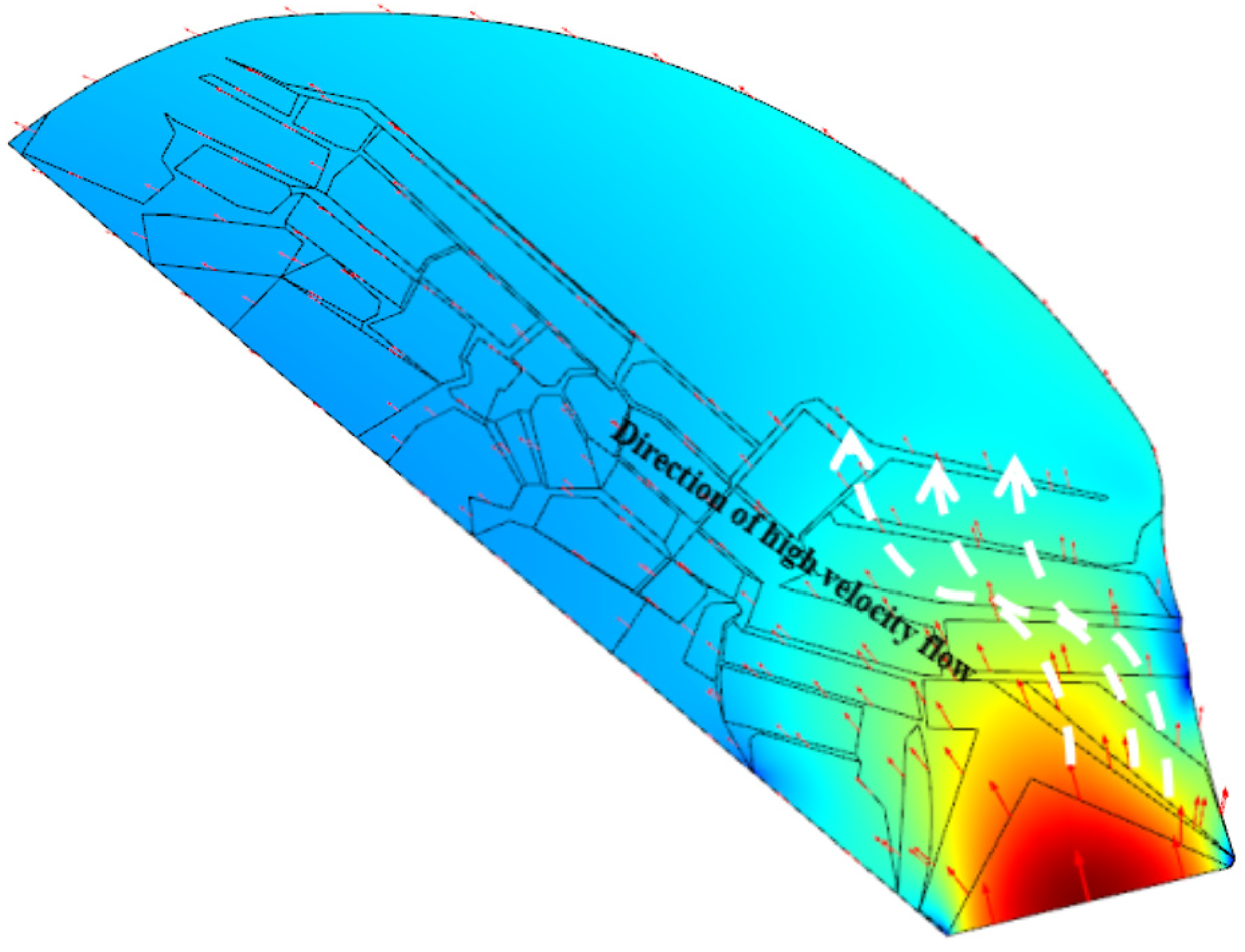
Vectorial distribution of seepage rate in fracture network.
The area with high seepage rate had the larger red arrow size and dense distribution of arrows. Also it could be seen that the area with the largest seepage rate was the white arrow curve area and the seepage rate of coal-bed methane was faster in the area with larger permeability in the fracture network area. This conclusion was the same as the previous one which embodied the numerical distribution of Borden_width/L in the fracture network area.
Furthermore the network fissure zone in Figure 10 was separately extracted as the research object the model was shown in Figure 14 and the dense grid was continued to be divided as shown in Figure 15. The section AB normal quality source entrance was implemented which was the same as the previous operation eventually formed seepage velocity vector diagram as shown in Figure 16 the white arrow indicated the area with the strongest seepage rate and the remaining positions were in the area with the lower seepage rate. The numerical calculation results obtained by extracting the fracture network were basically consistent with the results of the aforementioned model in Figure 10. At the same time the correctness of the mathematical equivalent model was further verified.
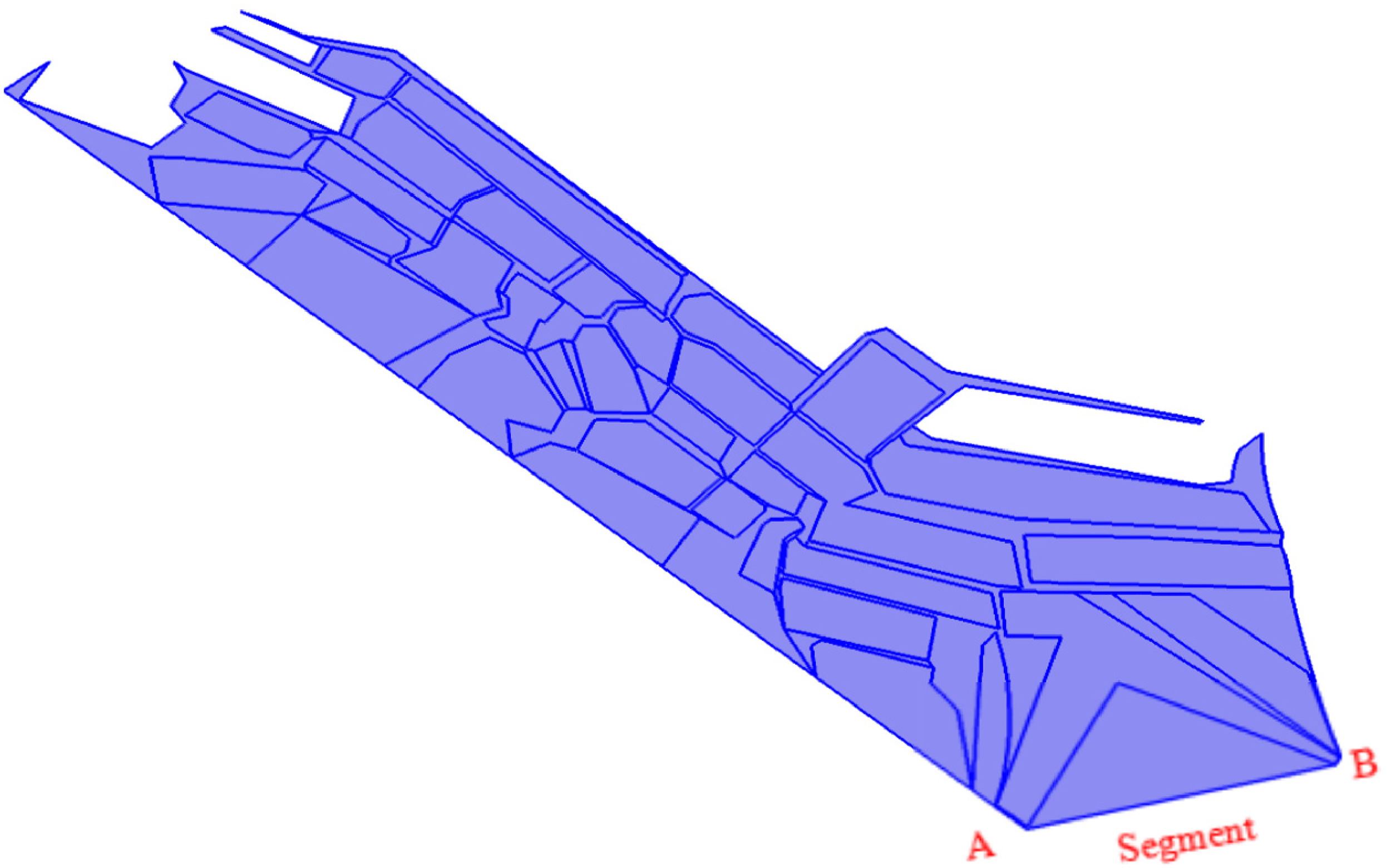
Fracture network extraction model.
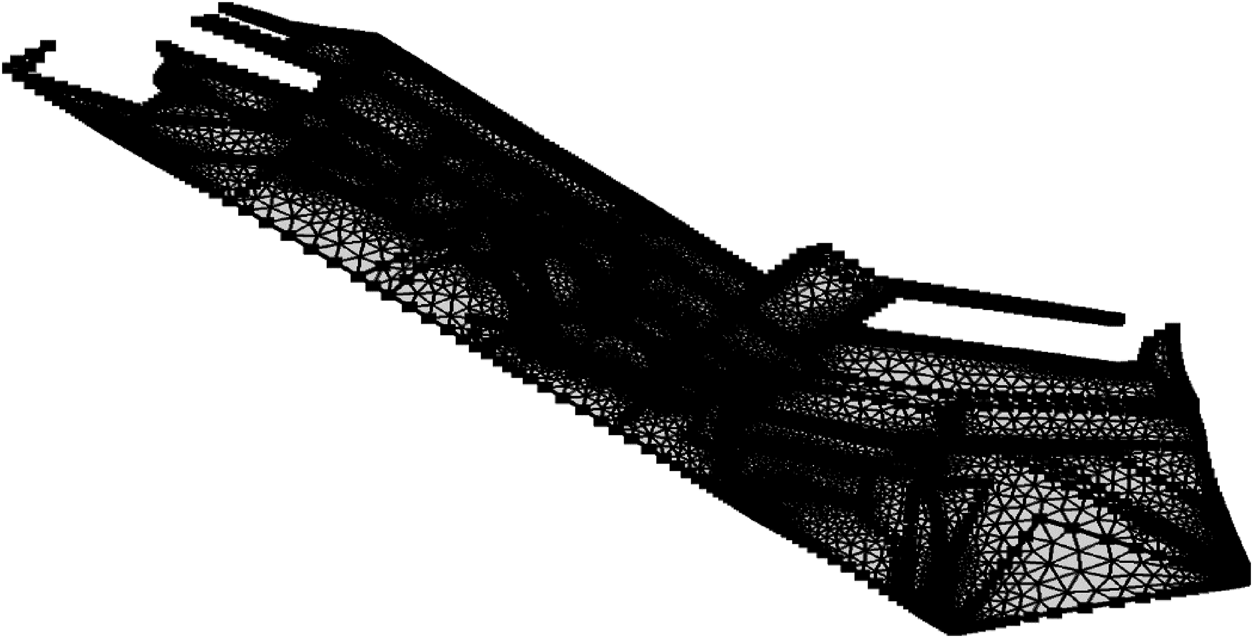
Dense mesh division of fracture network.
Extraction of seepage rate vector distribution in fracture network.
Conclusion
This article provided a new idea for solving the permeability and simulating the vector field of the coal-bed methane seepage velocity in extremely inclined goaf which has research value.
During the “transient” dangerous inversion process of the extremely inclined goaf there was the triangular hinged structure area and the mining length in the direction of the working face satisfied Formula (25) and the triangular hinge structure could remain stable; The single crack shape was equivalent to the elliptic arc-trapezoid combination shape parallelogram triangle and trapezoid which provided a simple mathematical model for solving the Borden_width of single crack; Extracting the network crack channels and solving the ratio of equivalent average width to equivalent length which facilitated the subsequent numerical simulation with Comsol software.
Supplemental Material
sj-docx-1-eea-10.1177_01445987221077364 - Supplemental material for Study on instability discriminating condition and permeability variation of triangle articulated structure in highly inclined goaf
Supplemental material, sj-docx-1-eea-10.1177_01445987221077364 for Study on instability discriminating condition and permeability variation of triangle articulated structure in highly inclined goaf by Song Qin, Haifei Lin, Zongyong Wei and Wei Shen in Energy Exploration & Exploitation
Footnotes
Acknowledgements
We gratefully acknowledge the financial support for this work provided by the National Natural Science Foundation of China (Grant no. 51874236; Grant no. 51674192) the National Youth Fund (Grant no. 51704228) Key Laboratory of Rock Mechanics and Geohazards of Zhejiang Province (Grant No. ZJRMG-2019-06).
Declaration of conflicting interests
The author(s) declared no potential conflicts of interest with respect to the research authorship and/or publication of this article.
Funding
The author(s) disclosed receipt of the following financial support for the research authorship and/or publication of this article: This work was supported by the National Natural Science Foundation of China (grant number 51874236; 51674192 ZJRMG-2019-06 51704228).
Supplemental material
Supplemental material for this article is available online.
References
Supplementary Material
Please find the following supplemental material available below.
For Open Access articles published under a Creative Commons License, all supplemental material carries the same license as the article it is associated with.
For non-Open Access articles published, all supplemental material carries a non-exclusive license, and permission requests for re-use of supplemental material or any part of supplemental material shall be sent directly to the copyright owner as specified in the copyright notice associated with the article.