
Abstract
The traditional stress arch hypothesis during longwall mining fails to elucidate the formation mechanism of stress arch, and the morphological characteristics and evolution of stress arch are indefinite. To solve these problems, a mechanical model was established for elucidating the formation mechanism of stress arch in overlaying strata. The influencing of key strata on the morphological characteristics of the stress arch was studied. Finally, the evolution of the stress arch during longwall mining was studied through numerical simulation. The results show that the bearing structure of the overlying strata served as the key strata, and the stress arch was formed when the key strata were subjected to deflection after playing a bearing structure role. This was the result of coordination and redistribution of major principal stress in the key strata. The morphological characteristics of the stress arch changed accordingly with the change in key strata. When the thickness of key strata and the distance between key strata and coal seam were gradually increased, the height and width of the stress arch increased accordingly; however, its height was always terminated at the top interface of key strata. At this time, the peak value of the abutment pressure of the working face gradually decreased while the influencing range gradually increased. During longwall mining, the stress arch developed upward by leaps and bounds with the bearing and fracture of key strata. When the overlying key strata were completely fractured, the stress arch disappeared. The results were verified using the field measurement data on the abutment pressure of the Y485 longwall face in Tangshan Mine.
Introduction
The arching effect of surrounding rock was first proposed by Ritter when observing the effect of burial depth on the distribution of surrounding rock stress of the tunnel (Ritter, 1879). Engesser (1882), Fayol (1885), Protodyakonov (1909), Terzaghi (1943), and Handy (1985) proposed an arching effect for unbonded soil mass. In recent years, the arching effect of soil mass has been the research focus in geotechnical engineering, including the shape of the stress arch (Du et al., 2011; Li et al., 2017a), stress distribution in stress arch (Pardo and Sáez, 2014; Wang et al., 2019), and application of the stress arch in geotechnical engineering. To be more specific, these are the distribution of surrounding rock stress in retaining wall (Goel and Patra, 2008; Paik and Salgado, 2003), stability of subgrade (Feng et al., 2017), stress coupling relationship between antislide pile and soil mass in slope (Chen and Martin, 2002), reinforcement of tunnel (Dai et al., 2020; Liu et al., 2018), exploitation of oil and gas (Li et al., 2017b; Wang et al., 2015; Zhang et al., 2020), and backfilling of tailings (Fahey et al., 2009; Li et al., 2019; Li et al., 2020).
The earliest theory using the arching effect of surrounding rock to explain the ground pressure during longwall mining is the stress arch hypothesis (Kratzsch, 1983). In this hypothesis, the stress arch is regarded as the bearing structure during overlying strata movement. During the strata movement, the stress arch transfers a load of overlying strata to the surrounding rock around the working face and forms the front and rear arch abutment with a stress-concentration zone in the coal seam and goaf. The front and rear arch abutments of the stress arch move forward during longwall mining, while the working face is always located in the stress-relief zone under the stress arch (Qian and Shi, 2003). It explains well the existence of abutment pressure around the stope and the reason that the working resistance of support is far less than the whole weight of overlying strata. However, in the stress arch hypothesis, the assumption that the rear arch abutment of the stress arch is located in the goaf has not been verified by experimentally or field measurements and even some studies (Yavuz, 2004) have shown that the stress in goaf can only be restored to the in-situ stress at most, without forming a stress-concentration zone. In recent years, with the progress in numerical simulation, more and more studies have been conducted on the stress arch. Especially, in numerical simulation research on the evolution of mining-induced stress field, the stress arch with principal stress concentration has been discovered as well (Du et al., 2011; Liu, 2019; Xie et al., 2009). A numerical simulation has better determined the stress distribution characteristics after the deformation of overlying strata during longwall mining and studied the morphological characteristics and evolution of the stress arch.
Previous studies (Xie and Wang, 2013) have shown that a stress arch in the overlying strata of the working face is only formed in the strata that support the overlying strata. This significantly differs when the arch structure in soil mass can be formed either in the unconsolidated layer without cohesive force or in the cohesive soil. Thus, it is necessary to further study the correlation between the formation of stress arch and the bearing structure of overlaying strata during longwall mining, morphological characteristics, and evolution characteristics of the stress arch with the change in the bearing structure of overlying strata. On this basis, it is necessary to study the influence of the stress arch on mining-induced stress distribution. In this paper, on the basis of the bearing structure of overlying strata, a mechanical model was established to elucidate the formation mechanism of stress arch and study the influencing of key strata on the morphological characteristics and evolution of the stress arch. The research results were verified by the field measurement data on the mining-induced stress of the Y485 working face in Tangshan Kailuan Mining Area.
Formation mechanism of the stress arch during longwall mining
The key strata theory (Qian et al., 1996) indicates that owing to different rock-forming time and mineral compositions, multilayer strata with different thicknesses and strengths are formed on the overlying strata. The strata that wholly or partially control the strata movement are known as the key stratum. The fracture of key stratum will cause the movement of the entire or a considerable part of the overlying strata. The former is known as the primary key stratum (PKS) and the latter is known as key stratum (KS). There might be more than one KS, but only one PKS in the overlying strata. KS serve as the bearing structure in bedrock. The KS theory enables the unified understanding and complete mechanical description of strata movement, ground pressure, mining-induced stress, and migration of water and gas.
Mechanical model
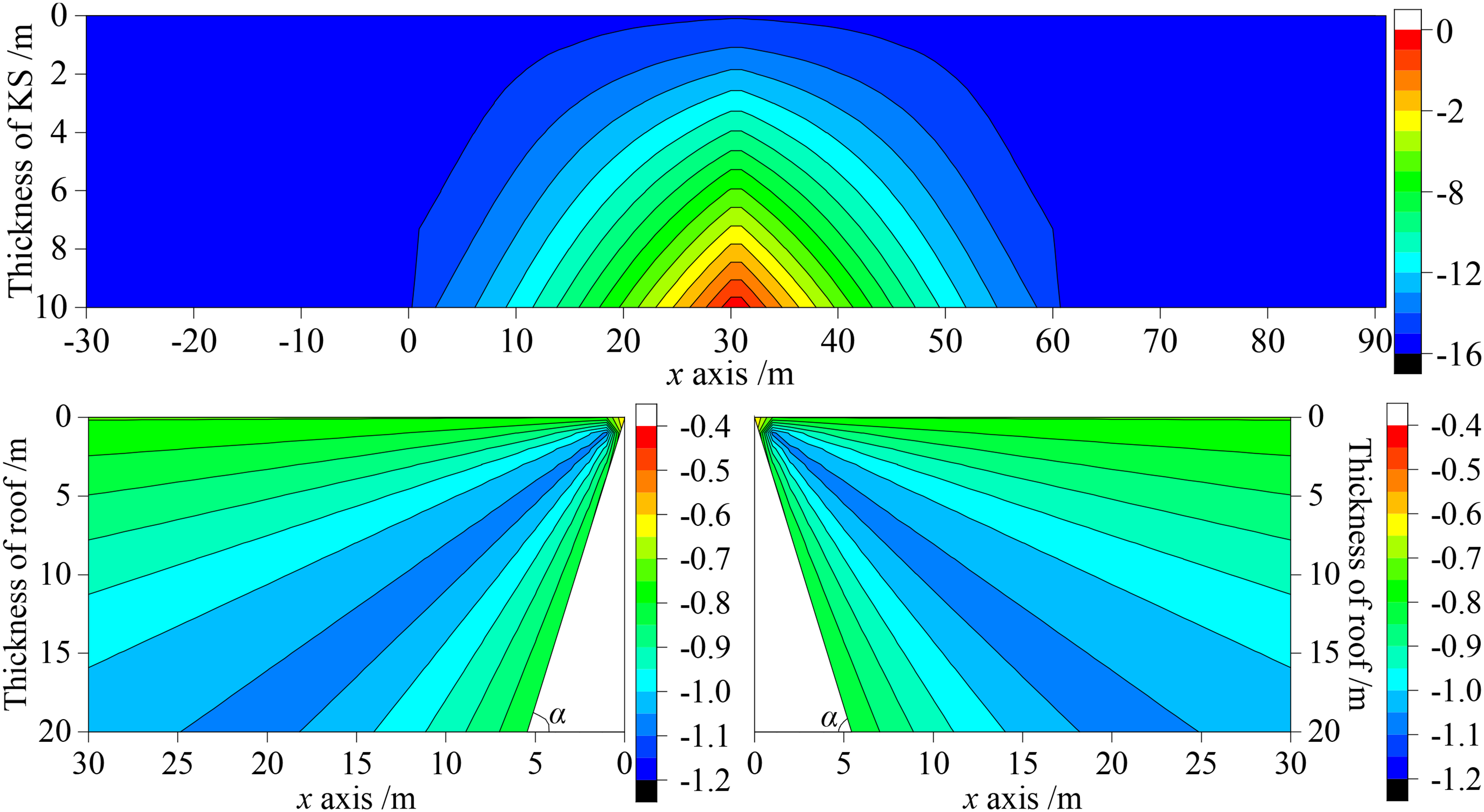
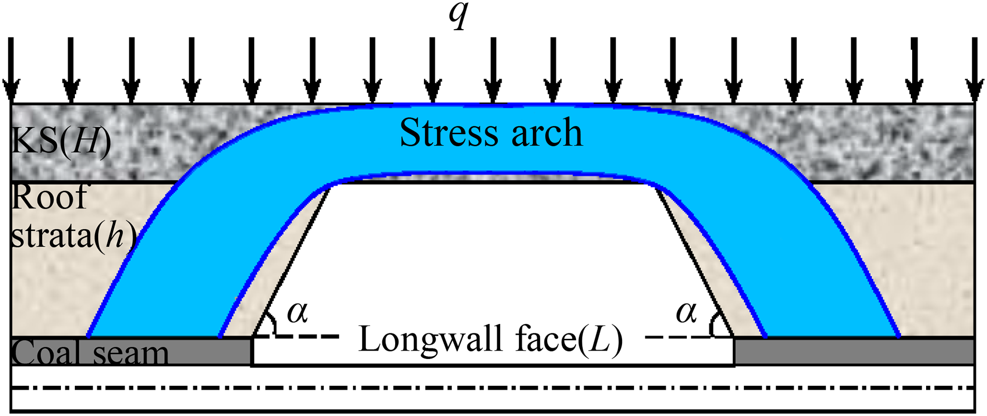
After the stopping of the working face, the immediate roof strata were caved, and the KS were subjected to deflection under a load of overlying strata. With the KS simplified as elastic foundation beam and the underlying immediate roof strata of KS regarded as Winkler elastic foundation, the supporting effect of caved immediate roof strata of working face on the KS was ignored, and the major principal stress distribution of KS and underlying immediate roof strata were studied. As shown in Figure 1, supposing that the span of KS is 2l, the thickness is H, the width is b, the load on the top interface of KS is q, the thickness of underlying immediate roof strata is h, the fracture angle of immediate roof strata is α, and the width of working face is L. The coordinate system was established as shown in Figure 1(a). The mechanical model for KS and the underlying immediate roof strata is divided into three isolated segments: elastic foundation beam I of KS (Figure 1(b)), elastic foundation beam II of KS (Figure 1(c)), and a wedge of immediate roof strata (Figure 1(d)).
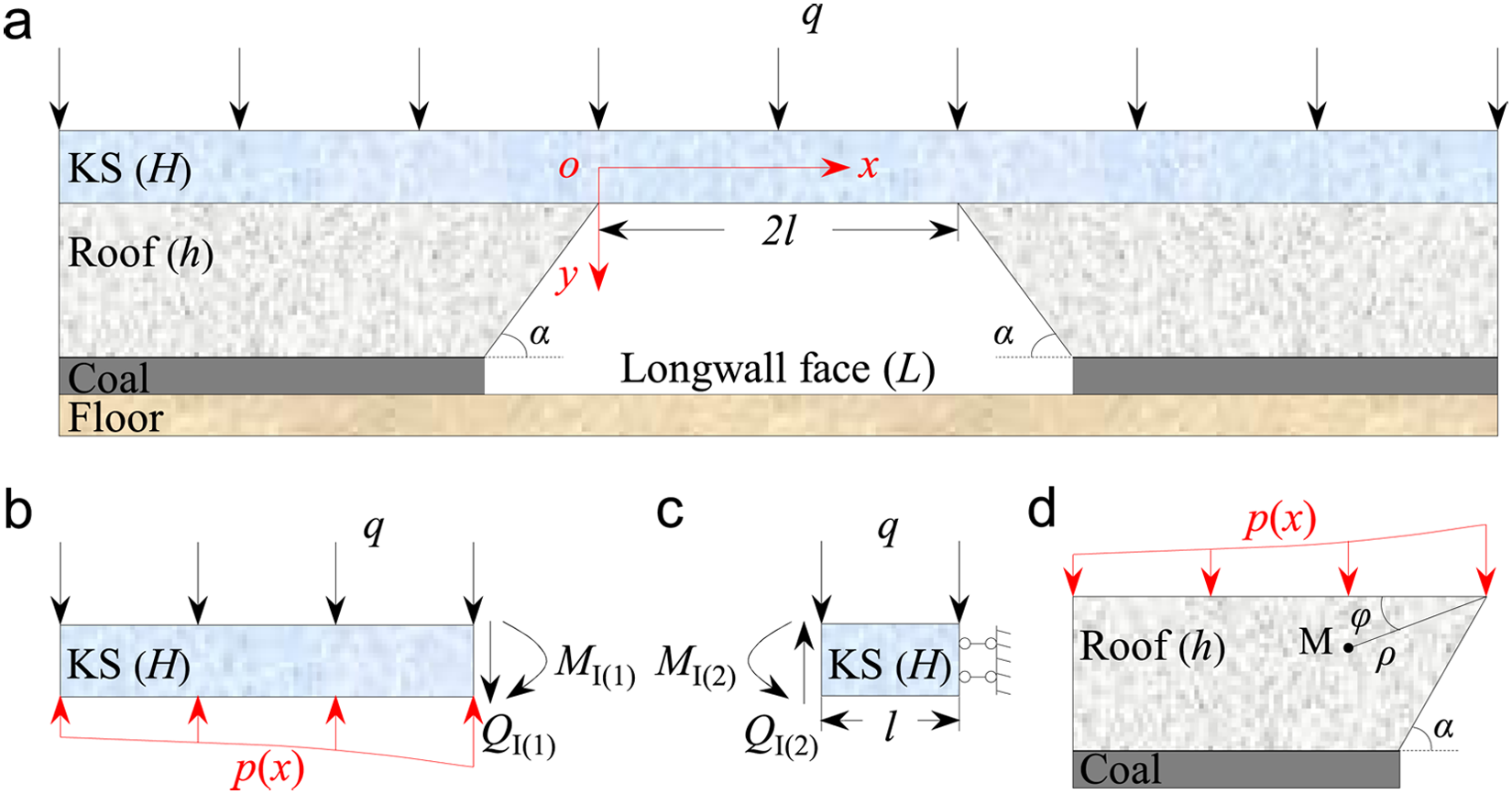
Mechanical model of the key stratum (KS) and the roof strata. (a) Schematic diagram of KS and the roof strata, (b) loading and stress distribution in the left side of KS, (c) loading and stress distribution in the right side of KS, (d) loading and stress distribution in the roof strata.
As shown in Figure 1(b), x∈(−∞, 0), with regard to the isolated segment I, under the action of overlying load q, the KS and underlying immediate roof strata form a semi-infinite elastic foundation beam (Hetenyi, 1946). The deflection differential equation for KS can be expressed as follows:

Obviously, the general solution to the above homogeneous linear differential equation can be expressed as follows:

As shown in Figure 1(c), x∈(0, l), with regard to isolated segment II under the action of overlying load q, the KS was a cantilever structure, and by taking the moment of load on KS to any section x, the deflection differential equation of cantilever beam can be obtained as follows:


As shown in Figure 1(d), the immediate roof strata are a wedge complying with the basic assumption conditions of elastic mechanics, and its load is p(x). p(x) is the counter-force transferred from the KS to the elastic foundation, which can be obtained from the deflection analytical formula for the KS. Supposing that M(φ, ρ) is any point in the immediate roof strata, the polar coordinates of the stress component of Point M can be obtained according to elastic mechanics as follows (Xu, 2019):
Theoretical analysis results of major principal stress distribution. (a) Major principal stress distribution of key stratum, (b) major principal stress distribution in the left side of the roof, (c) major principal stress distribution in the right side of the roof.
Sketch of major principal stress distribution.
Under the loading stress, a stress arch with a concentrated major principal stress is formed in the KS and immediate roof strata. The major principal stress contour on the section is arched. Besides, a radiated stress-concentration zone is formed on immediate roof strata, and immediate roof strata are the skewback of the stress arch. A stress arch is formed when the key stratum were subjected to deflection after playing a bearing structure role, and it is the result of coordination and redistribution of major principal stress in the KS.
Numerical simulation
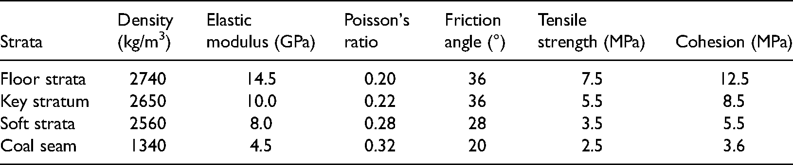
FLAC3D was used to study the distribution of major principal stress in the KS under the uniformly distributed load. The numerical model is consistent with the theoretical analysis model. The basic size of the model is 200 m × 10 m × 50 m (length × width × height). The assumption in the numerical model is elastic and homogeneous, isotropic, and elastoplastic, obeying the Mohr–Coulomb criterion. A KS was set in the model with a thickness of 10 m. At the top interface of the KS, the uniformly distributed load was 1.0 MPa. The excavation width of the working face is 80 m. The mechanical parameters of each rock stratum in the numerical simulation are shown in Table 1. The distribution of the major principal stress in the KS and the immediate roof strata are shown in Figure 4. Consistent with the theoretical calculation results, under the loading stress, a connected stress arch with a concentrated major principal stress is formed in the KS and immediate roof strata. A stress arch is formed when the KS was subjected to deflection after playing a bearing structure role, and it is the result of coordination and redistribution of major principal stress in the KS.
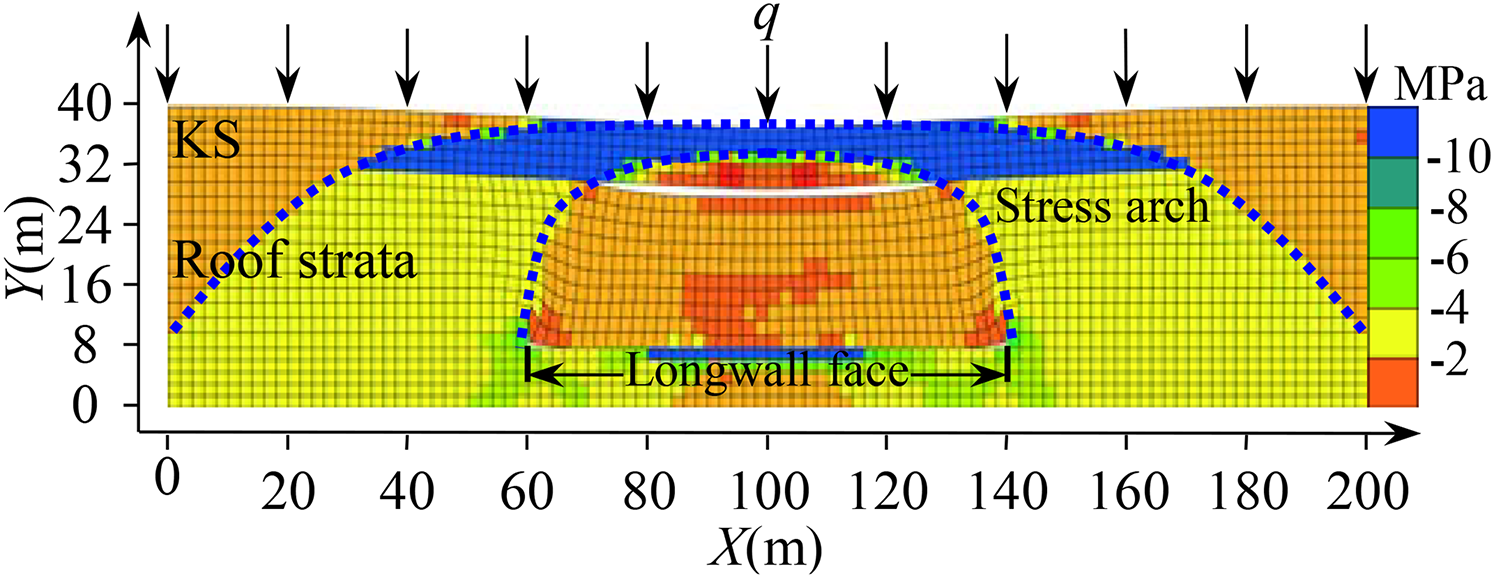
Numerical simulation results of major principal stress distribution.
Mechanical parameters of the rock mass.
Therefore, during the strata movement, from the perspective of the overlying strata structure, the KS is the bearing structure in the overlying strata and controls the movement of the roof strata. Before the stopping of the working face, due to the existence of the in-situ stress field, the major principal stress is distribution in the horizontal and vertical directions, which are perpendicular (the tectonic stress field is not considered). After the stopping of the working face, the in-situ field is disturbed, and the roof strata are subjected to deflection and fracture, making the major principal stress in the overlying strata redistributed. After the redistribution of major principal stress, a stress arch is formed in the KS. Therefore, unlike the KS structure, a stress arch does not exist objectively in the roof strata. This is formed when the KS were subjected to deflection after playing a bearing structure role, and it is the result of coordination and redistribution of major principal stress in the KS.
Effects of KS on morphological characteristics of the stress arch
The effect of the thickness of the KS and the distance between the KS and coal seam on the morphological characteristics of the stress arch was evaluated by numerical simulation. The model is 1000 m long and 5 m wide. The assumption in the numerical model is elastic and homogeneous, isotropic, and elastoplastic, obeying the Mohr–Coulomb criterion. In the model, one KS was set, and the coal seam thickness is 4 m. Three different groups of KS thickness (10, 20, and 30 m) and three different groups of distances from coal seam (20, 40, and 60 m) were set. Besides, a group of comparison models was set without a KS to compare the distribution of major principal stress in the roof strata. On the top interface of the KS, the load of overlying soft rock strata was replaced with a uniformly distributed load. In different research programs, the in-situ stress of the coal seam was kept constant by adjusting the overlying load. The mechanical parameters for each rock stratum in the numerical model are shown in Table 1.
Figure 5 shows the distribution of the major principal stress field in the overlying strata when the width of the working face is 200 m.
When there is no KS in the overlying strata (Figure 5(a)), the soft rock cannot support the overlying strata. The overlying strata will be fractured with the stopping of the working face. At this time, the roof strata above the working face are in a major principal stress-relief zone, resulting in the unsuccessful formation of stress arch with concentrated major principal stress. When a KS exists in the overlying strata, owing to the bearing effect of KS on the overlying strata, a stress arch with a concentrated major principal stress is formed in the overlying strata during longwall mining, and the form of the stress arch is related to the thickness of the KS and the distance between the KS and coal seam (Figure 5). When the distance between the KS and coal seam remains constant (e.g. the distance is 20 m, as shown in Figures 5(b), (e), and (h)), with increasing thickness of the KS, the height of the stress arch gradually increases, and the thickness of abutment of the stress arch increases from 15 to 35 m. When the distances between the KS and coal seam are 40 and 60 m, the morphological characteristics of the stress arch also change accordingly with the increasing thickness of the KS. Obviously, the morphological characteristics of the stress arch change by varying the distance between the KS and coal seam, but the height of the stress arch reaches the top interface of the KS. When the thickness of the KS remains constant (e.g. the thickness is 10 m, as shown in Figures 5(b)–(d)), the morphological characteristics of the stress arch change significantly with increasing distance between the KS and coal seam. For example, the thickness of the abutment of the stress arch increased from 15 to 50 m. When the thickness of the KS is 20 and 30 m, the morphological characteristics of the stress arch also changed with increasing distance between the KS and coal seam. When the thickness of the KS changes, the height of the stress arch still reaches the top interface of the KS.
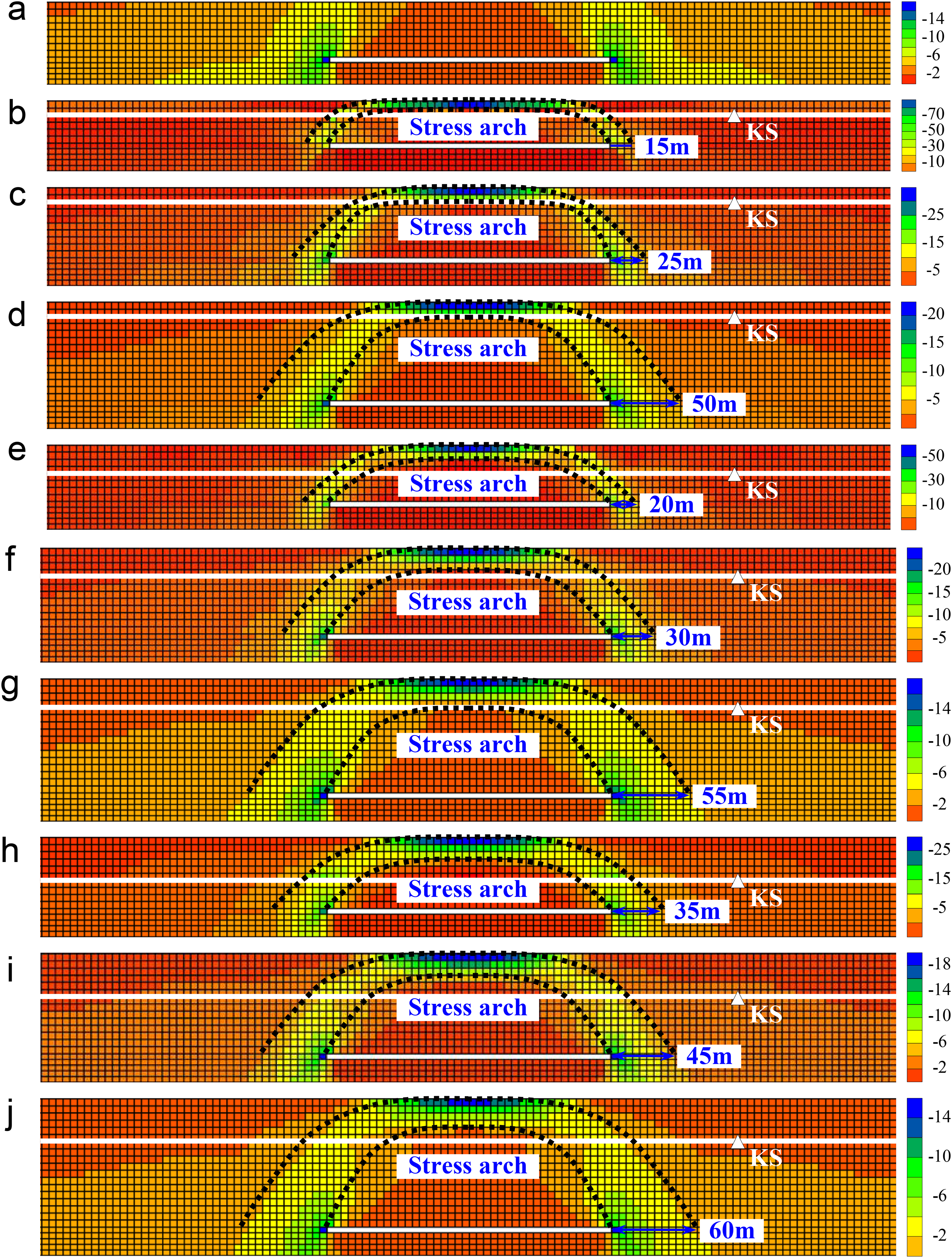
Effect of KS on the morphological characteristics of pressure arch. (a) The thickness of KS equals to 0, (b) H = 10 m, h = 20 m, (c) H = 10 m, h = 40 m, (d) H = 10 m, h = 60 m, (e) H = 20 m, h = 20 m, (f) H = 20 m, h = 40 m, (g) H = 20 m, h = 60 m, (h) H = 30 m, h = 20 m, (i) H = 30 m, h = 40 m, and (j) H = 30 m, h = 60 m (unit: MPa).
Figures 6 to 8 show the distribution of abutment pressure on both sides of the working face under the influence of the KS. When the thickness of the KS remains constant, with increasing distance between the KS and coal seam, the height and thickness of the stress arch in the roof strata gradually increase. At this time, the peak value of abutment pressure on both sides of the working face gradually decreases, while the load transfer distance of abutment pressure gradually increases with the increasing thickness of the stress arch. When the distance between the KS and coal seam remains constant, the height and thickness of the stress arch in the roof strata also gradually increase with the increasing thickness of the KS. At this time, the peak value of abutment pressure gradually decreases, while the load transfer distance of abutment pressure increases with the increasing thickness of the stress arch.
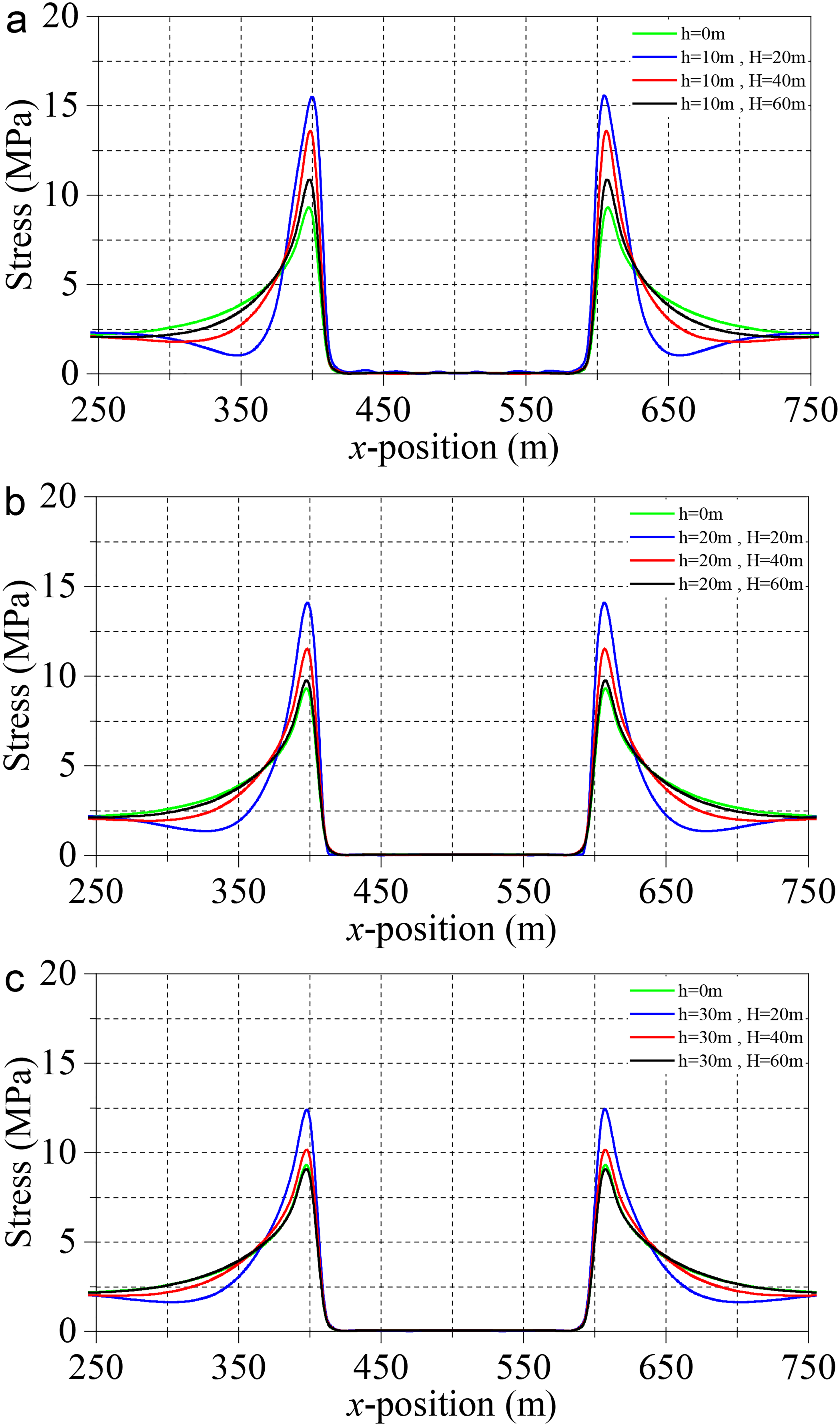
Effect of the height of KS on the mining-induced stress ahead of the longwall face: (a) h1 = 10 m, (b) h2 = 20 m, and (c) h3 = 30 m.
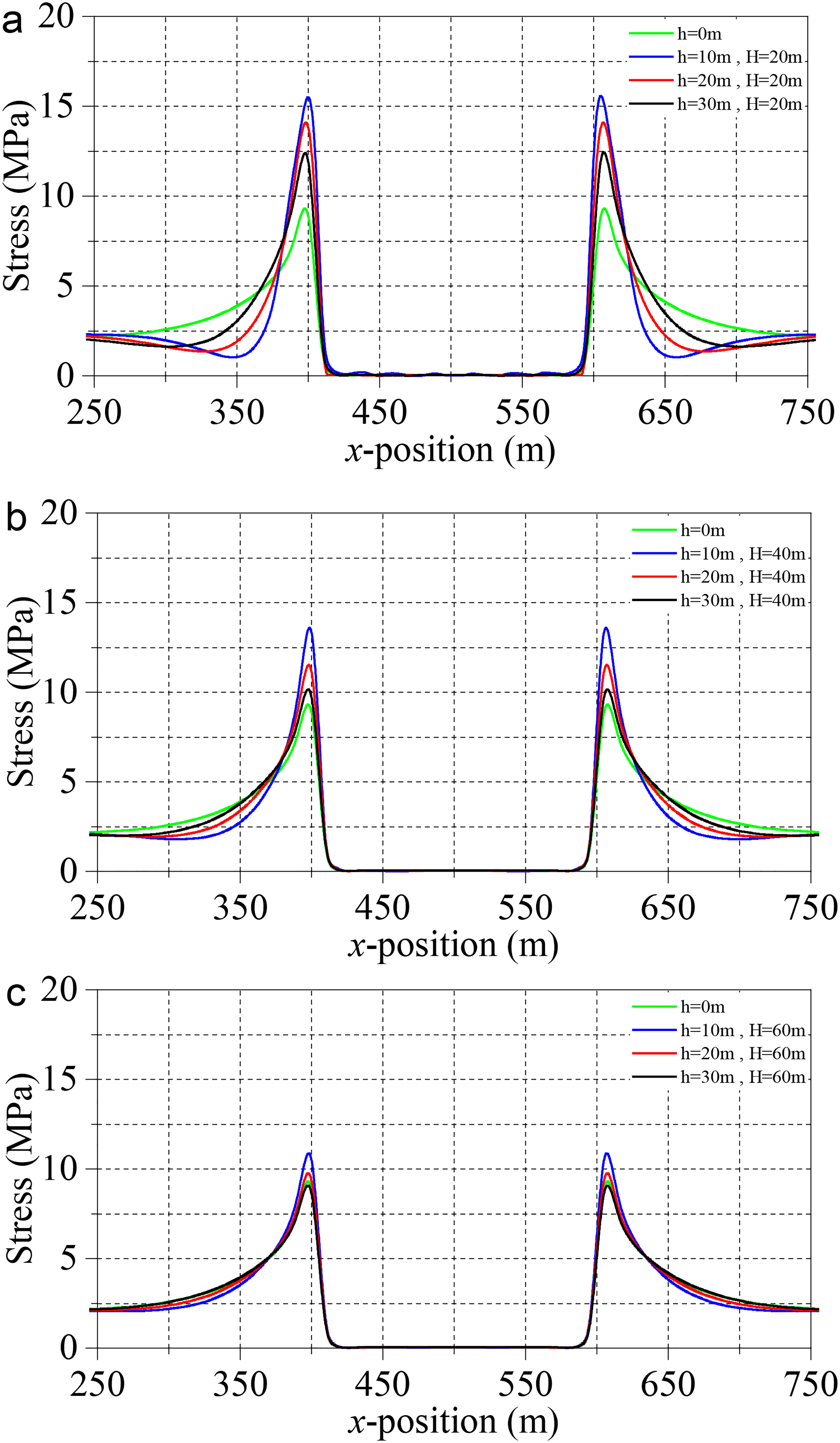
Effect of the thickness of KS on the mining-induced stress ahead of the longwall face: (a) H1 = 20 m, (b) H2 = 40 m, and (c) H3 = 60 m.
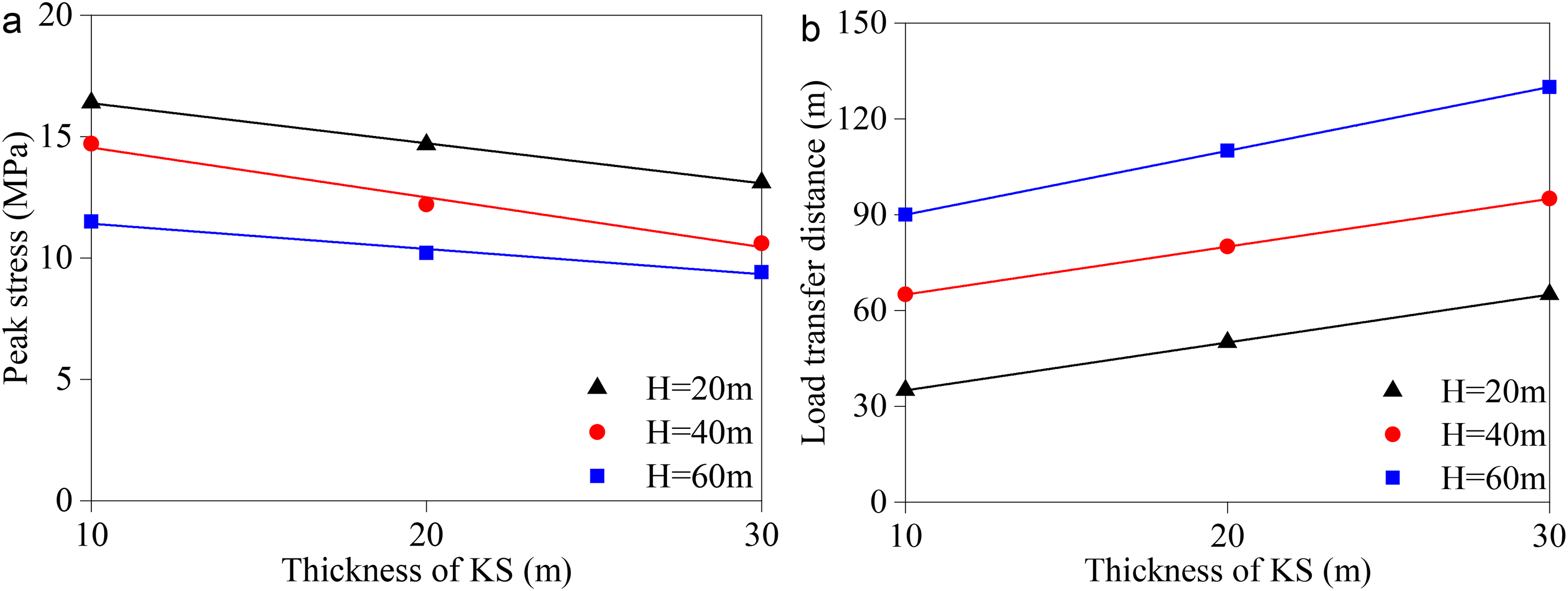
Evolution of peak stress and load transfer distance with the height and thickness of KS: (a) evolution of peak stress and (b) evolution of load transfer distance.
Evolution of the stress arch during longwall mining
Numerical simulation scheme
A numerical model was designed to study the evolution of the stress arch with key stratum during longwall mining, as shown in Figure 9. The assumption in the numerical model is elastic and homogeneous, isotropic, and elastoplastic, obeying the Mohr–Coulomb criterion. In the model, two key strata were set, including a KS with a thickness of 15 m and a PKS with a thickness of 20 m. A vertical load of 4.0 MPa was applied to the top interface of the model to simulate the weight of 200 m strata. The mechanics’ parameters in the model are the same as those shown in Table 1. In the numerical simulation, the width of the working face is 200 m; the length of the working face is 300 m, and the mining height is 4 m. During the experiment, the working face was excavated at an interval of 20 m.
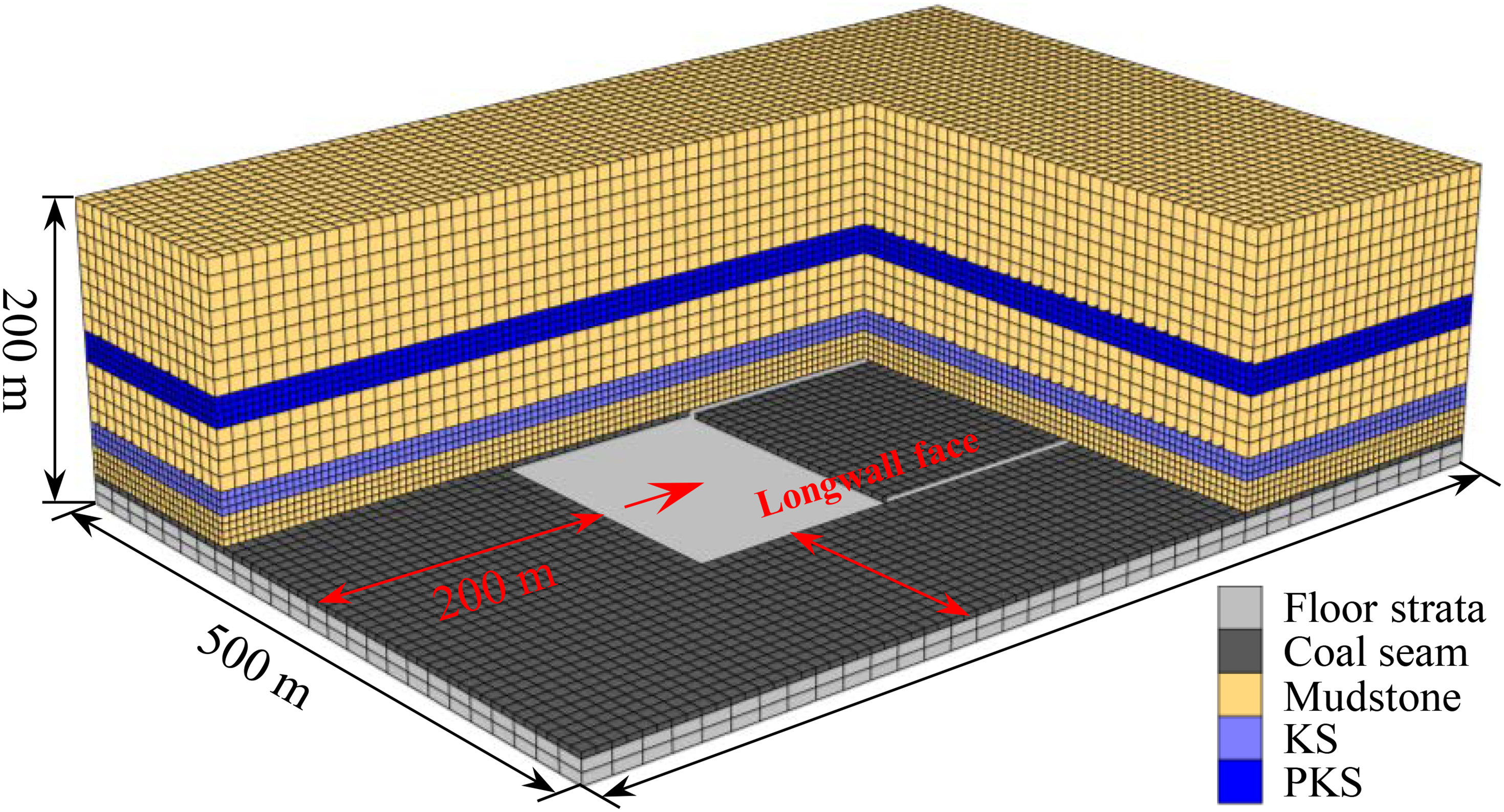
Flac3D model.
Results and analysis
Figure 10 shows the evolution of the major principal stress field of overlying strata on the middle section of the working face during longwall mining.
When the length of the working face is 60 m, an obvious major principal stress concentration occurs in the roof strata on both sides of the working face, while the major principal stress changes less on the section of the KS, without forming a stress arch. As the working face continues to advance forward, the advanced stress-concentration zone moves forward, and the stress-concentration zone in the roof strata on both sides of the working face gradually expands to the KS. When the mining width increases, the KS begins to support the overlying strata. The stress-concentration zone in the KS and that on both sides of the working face connect to form a stress arch. The formation of a stress arch represents the bearing effect of the KS, as shown in Figure 10(b). Then, with an increase in the width of the working face, the bearing characteristics of the KS increase, and the major principal stress on the cross-section of the KS increases accordingly, as shown in Figure 10(c). When the major principal stress in the KS exceeds elastic strength and the KS is in a plastic state, the KS can still exert a bearing effect. However, as clearly shown in Figure 10(d), the bearing capacity of the KS gradually decreases. The major principal stress decreases. The bearing capacity of the KS is gradually transferred to the PKS. The stress arch of the PKS is formed, and the bearing characteristics are reflected. With the gradual increase in the bearing capacity of the PKS, the major principal stress on the section of the PKS increases accordingly. When the PKS plays the bearing role, the evolution process “forming—developing—failure” of the stress arch is the same as that of the stress arch in the KS. When the major principal stress exceeds the ultimate strength of the PKS and the PKS is in a plastic state, the stress arch disappears.
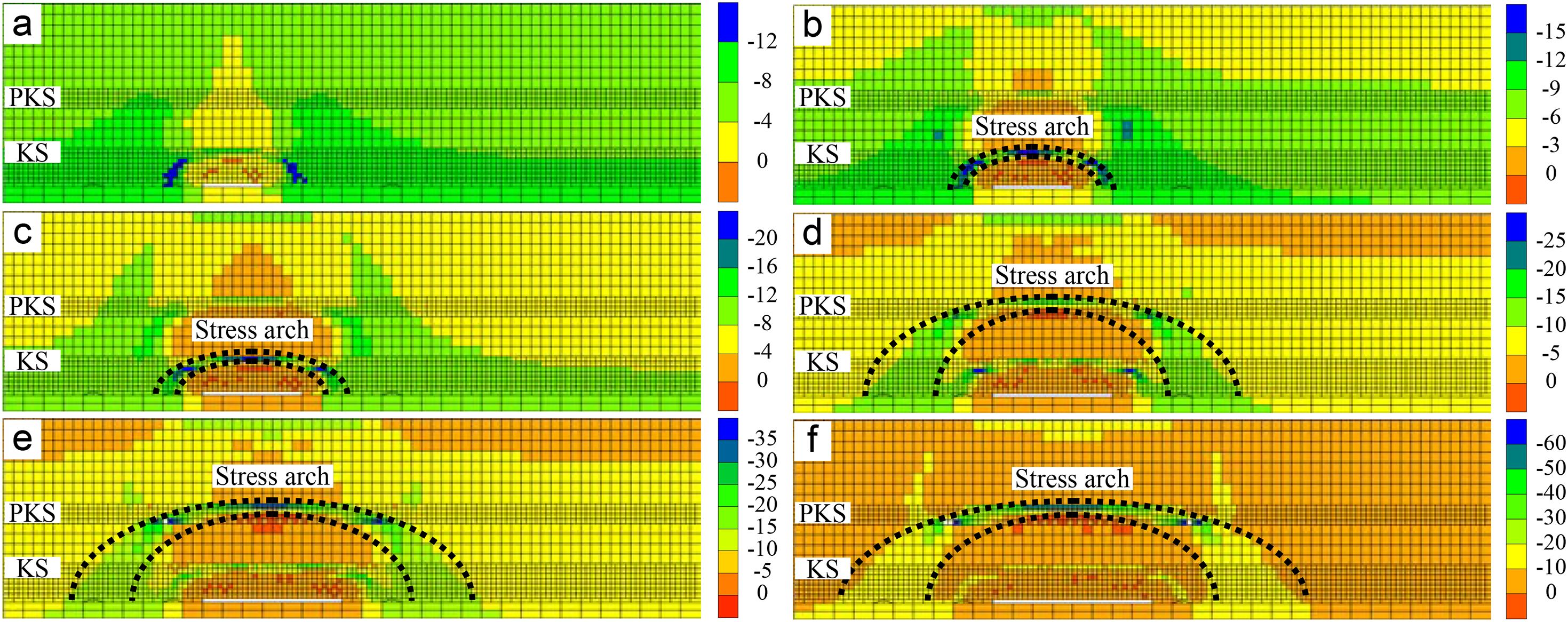
Evolution of pressure arch along the strike direction with different mining lengths: (a) 60 m, (b) 80 m, (c) 100 m, (d) 120 m, (e) 140 m, and (f) 160 m (unit: MPa).
Figure 11 shows the distribution of major principal stress on the dip section during longwall mining. Similar to the evolution of major principal stress on the strike section, the process of “forming—developing—failure” of the dip stress arch in the working face evolves with the KS from exerting a bearing effect to suffering failure and losing bearing performance.
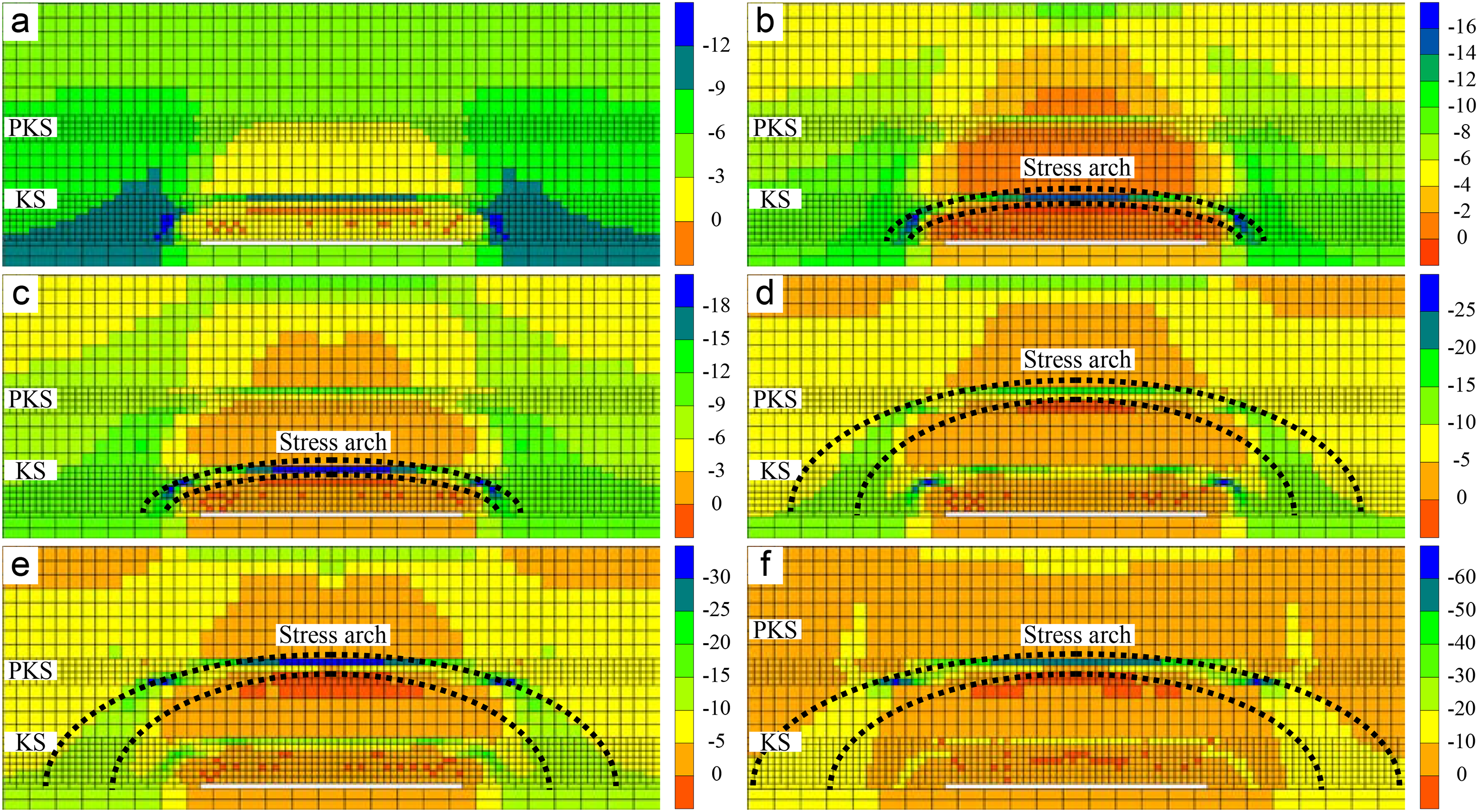
Evolution of pressure arch along the dip direction with different mining lengths: (a) 60 m, (b) 80 m, (c) 100 m, (d) 120 m, (e) 140 m, and (f) 160 m (unit: MPa).
Figure 12 shows the evolution of abutment pressure on both sides of the working face during longwall mining. As shown in Figures 10 and 11, when the mining width of the working face is <100 m, the bearing structure of overlying strata is a KS, and a stress arch effect is formed. When the mining width of the working face is >100 m, the stress arch is composed of a PKS and the underlying strata of the PKS. During longwall mining, the stress arch jumps from the KS to the PKS. Under this condition, the peak value for advanced abutment pressure on the working face decreases, while its load transfer distance increases, that is, with the increase in the thickness of the KS and the distance between KS and coal seam, the height and thickness of stress arch increase. The peak value of abutment pressure of the working face gradually decreases, and the load transfer distance of abutment pressure is gradually extended.
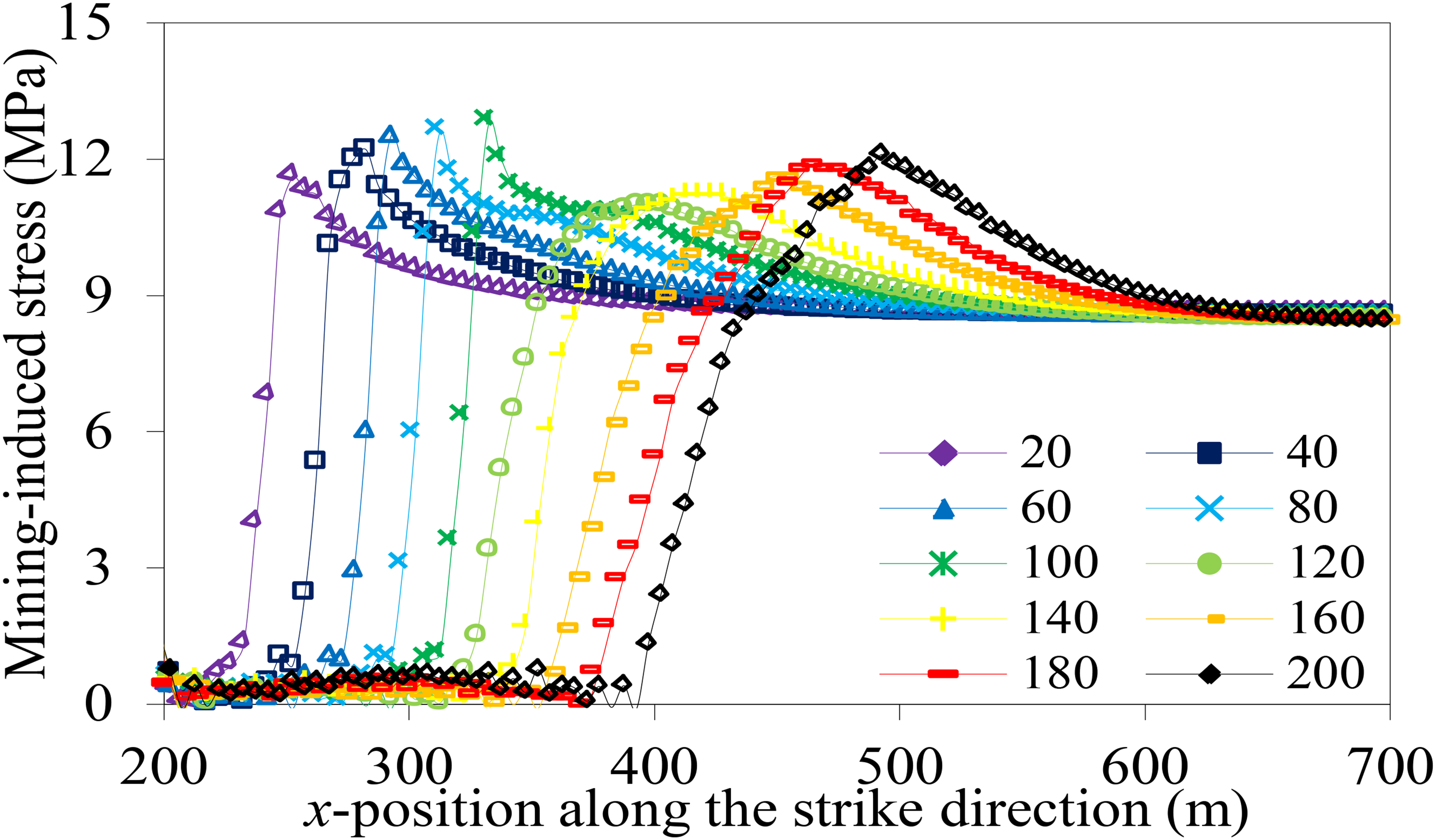
Evolution of mining-induced stress ahead of the longwall face with different mining lengths.
Field verification
Site descriptions
The width of the Y485 working face in the Tangshan Mine of Kailuan Group is 150 m. The length along the strike is 775 m. The average thickness of 9# coal seam is 9.8 m. The burial depth is 80 to 1030 m. The Y485 working face is adjacent to the goaf of the Y486 working face on the south and to the solid coal area on the north. 5# coal seam is located in the roof of 9# coal seam, and the average vertical distance between the two coal seams is 35 m. The working faces 8455, T1451, T1452, T1453, and T1454 in 5# coal seam were mined in 1998, 2004, 2007, 2009, and 2010, respectively, with the average mining height of the working face being 3.5 m. The area of the Y485 working face moving forward by 255 m from the open-off cut was located below the solid coal in the 5# coal seam, and later, it was located below the goaf. According to the characteristic results of KS, six key strata exist in the roof of 9# coal seam, with one KS existing between 5# and 9# coal seams, as shown in Figure 13.
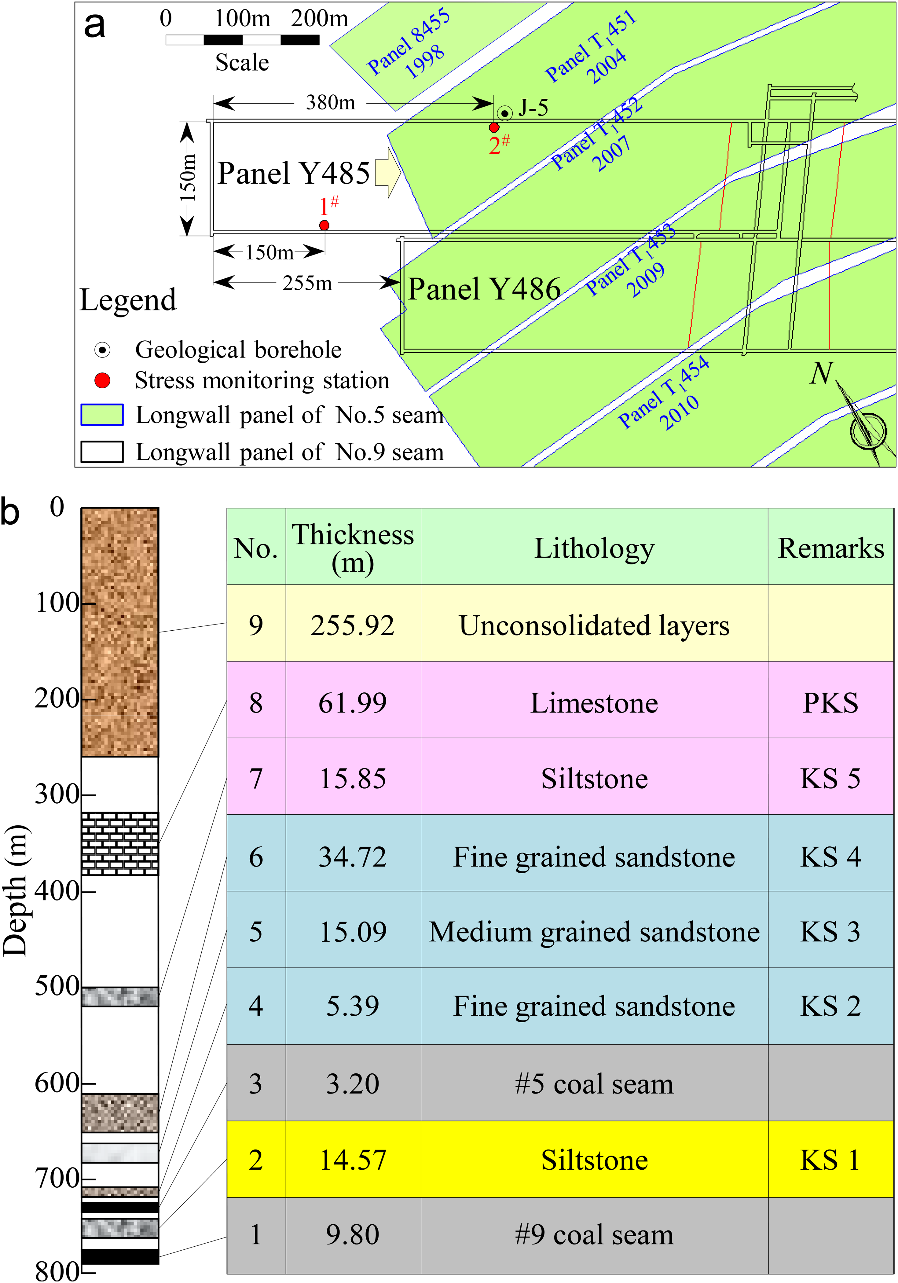
Geological conditions of Y485. (a) Layout of longwall panel Y485, (b) identification results of key strata in J-5 borehole.
To analyze the effect of KS on the advanced abutment pressure of the Y485 working face, two groups of measurement stations were arranged in the Y485 working face: 1# measurement station was arranged below the solid coal of 5# coal seam, 150 m from the open-off cut of the working face; 2# measurement station was arranged below the goaf of 5# coal seam, 380 m from the open-off cut. To avoid the effect of lateral abutment pressure of Y486 goaf on the advanced abutment pressure, 2# measurement station was arranged at the side of air-return roadway of working face. Three borehole stress meters were arranged in each group of measurement stations, with a borehole depth of 10 m and a borehole diameter of 70 mm. The horizontal distance between two adjacent boreholes was 5 m, and the distance between borehole and roadway floor was 2.0 m.
Results of field measurements
After half a year's continuous monitoring, some of the six monitoring points have a too long monitoring period due to their early arrangement, leading to a plastic damage around the borehole wall. The monitored data are lower than the in-situ stress before the working face affects the measuring points; therefore, this part of borehole data was ignored in the analysis. At the same time, the original data were normalized because the data monitored by the pressure sensor represent the change in stress. The data of borehole stress gauges in stations 1# and 2# were selected for analysis, as shown in Figure 14. Because the peak value of abutment pressure cannot be monitored from the field measurement data, only the load transfer distance of abutment pressure was analyzed in this study.
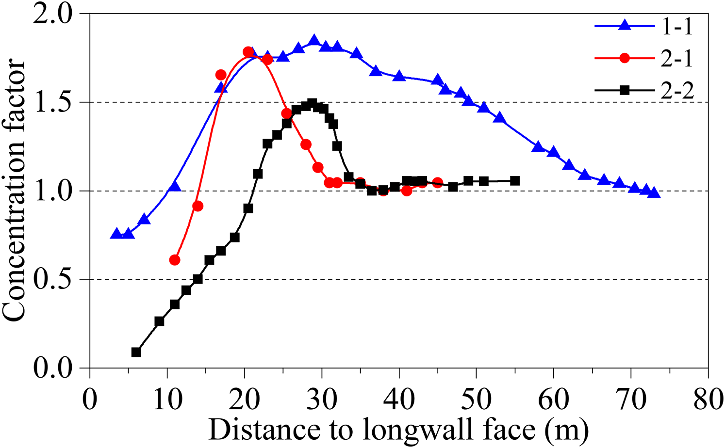
Curves of measured data in the site.
During the longwall mining of the Y485 working face, the KS 1, KS 2, KS 3, and KS 4 had a definite influence on abutment pressure, while other KS did not exert any effect (Guo, 2015; Wang et al., 2016). When the working face was located in the area of 1# measurement station, 5# coal seam in the roof in this area was in the initial stress state. The stopping of the Y485 working face was not affected by the mining of overlying coal seam. Under the influence of KS 1, KS 2, KS 3, and KS 4, the load transfer distance of abutment pressure is 73 m. However, when the working face was located in the area of the 2# measurement station after the overlying 5# coal seam was mined, the KS 2, KS 3, and KS 4 in the roof were completely fractured, while the KS 1 between the layers was not fractured, without being influenced by the mined 5# coal seam. At this time, the KS affecting the abutment pressure during mining in the Y485 working face evolved from the influence of the superposition of four key strata to that of a single KS 1 between layers. The load transfer distance of advanced abutment pressure in the working face from field measurement decreased to 38 and 36.5 m. The greater the thickness of KS affecting the abutment pressure in the working face, and the larger the distance between KS and coal seam, the larger the span of the stress arch and the greater the thickness of the stress arch in the coal seam. Therefore, under the influence of the stress arch, the load transfer distance of abutment pressure is larger. These research findings were verified via field measurement data on the abutment pressure of the Y485 working face in the Tangshan Kailuan Mining Area.
Conclusions
A mechanics model was established to reveal the formation mechanism of stress arch in the overlying strata during longwall mining. Unlike the key stratum structure objectively existing in the roof strata, a stress arch was formed when the key stratum was subjected to deflection after playing a bearing structure role. This is the result of coordination and redistribution of major principal stress in key stratum.
The morphological characteristics of the stress arch changed by varying the key stratum. When the thickness of key stratum and the distance between key stratum and coal seam increased gradually, the height and width of the stress arch increased accordingly. The peak value of abutment pressure on both sides of the working face decreased gradually, while the load transfer distance increased with the increasing thickness of the stress arch. However, the height of the stress arch always terminated at the top interface of the key stratum structure.
The evolution of pressure arch during longwall mining was revealed. During longwall mining, a stress arch was formed not in any stratum in the roof strata but in the key stratum exerting a bearing effect on overlying strata. The stress arch developed upward by leaps and bounds with the bearing and fracture of key stratum. When the overlying key stratum of the working face were completely fractured, the stress arch disappeared. The theoretical analysis and numerical simulation results obtained in this study were verified by the field measured data.
Footnotes
Declaration of conflicting interests
The authors declared no potential conflicts of interest with respect to the research, authorship, and/or publication of this article.
Funding
The authors disclosed receipt of the following financial support for the research, authorship, and/or publication of this article: This work was supported by the National Natural Science Foundation of China (51904162), China Postdoctoral Science Foundation(2020M682208), and Key Laboratory of Safety and High-efficiency Coal Mining,Ministry of Education (Anhui University of Science and Technology) (JYBSYS2019205).