
Abstract
Vacuum freeze-dryer has been widely used in many fields such as food, medicine, and beverage. In the actual operation process, the freeze-dryer and factory buildings need to consume a lot of cold energy. In order to reduce energy consumption, this paper presents a freeze-dryer system using solar energy absorption refrigeration in conjunction with buildings. Through the solar absorption refrigeration system, the cooling capacity is supplied to the freeze-dryer and the building at the same time, so that the cold can be cascaded utilization. The simulation of the system by TRNSYS software shows that the system can greatly reduce the consumption of conventional energy, and it is a new energy-saving measure of vacuum freeze-dryer and building air conditioning.
Introduction
The principle of vacuum freeze-drying is to freeze the wet material into solid state first, then sublimate the solid water in the material directly into gaseous state without passing through liquid state under the condition of keeping vacuum, so as to achieve the purpose of material dehydration and drying. The sublimated gaseous water is removed by re-condensing into ice through the cold trap coil (Shingisov and Alibekov, 2017; Šumić et al., 2016). This technological characteristic determines that in the process of freezing material and condensation gas water, the freeze-dryer needs to use refrigeration system to transport a large amount of cold energy to the drying box and cold trap. Therefore, the refrigeration system is the most important part of the freeze-dryer, known as the “heart of the freeze-dryer,” but also the most energy-consuming system of the freeze-dryer system (Li, 2003; Zhao, 2008). The excessive energy consumption of the freeze-dryer’s refrigeration system results in the excessive cost of the freeze-dryer. Therefore, reducing the energy consumption of refrigeration system in vacuum freeze-drying process is the key to energy-saving transformation of freeze-dryer.
In order to ensure the quality of freeze-dried products in vacuum freeze-drying workshop, the cleanliness and temperature and humidity of air conditioning system have high requirements. Such air conditioning system will certainly consume a lot of energy. However, in the actual operation process, both the freeze-dryer and the factory building have a set of refrigeration system and operate independently, which leads to low energy efficiency and serious waste. How to combine the two refrigeration systems organically, so that the refrigeration system can be fully and reasonably utilized, and ultimately achieve the purpose of energy-saving and consumption reduction, is the focus of this paper.
Energy consumption of vacuum freeze-dryer
Vacuum freeze-dryer is generally composed of hydraulic system, refrigeration system, circulation system, vacuum system, heating system, steam sterilization system, control system, etc. (Shi et al., 2010), as shown in Figure 1.
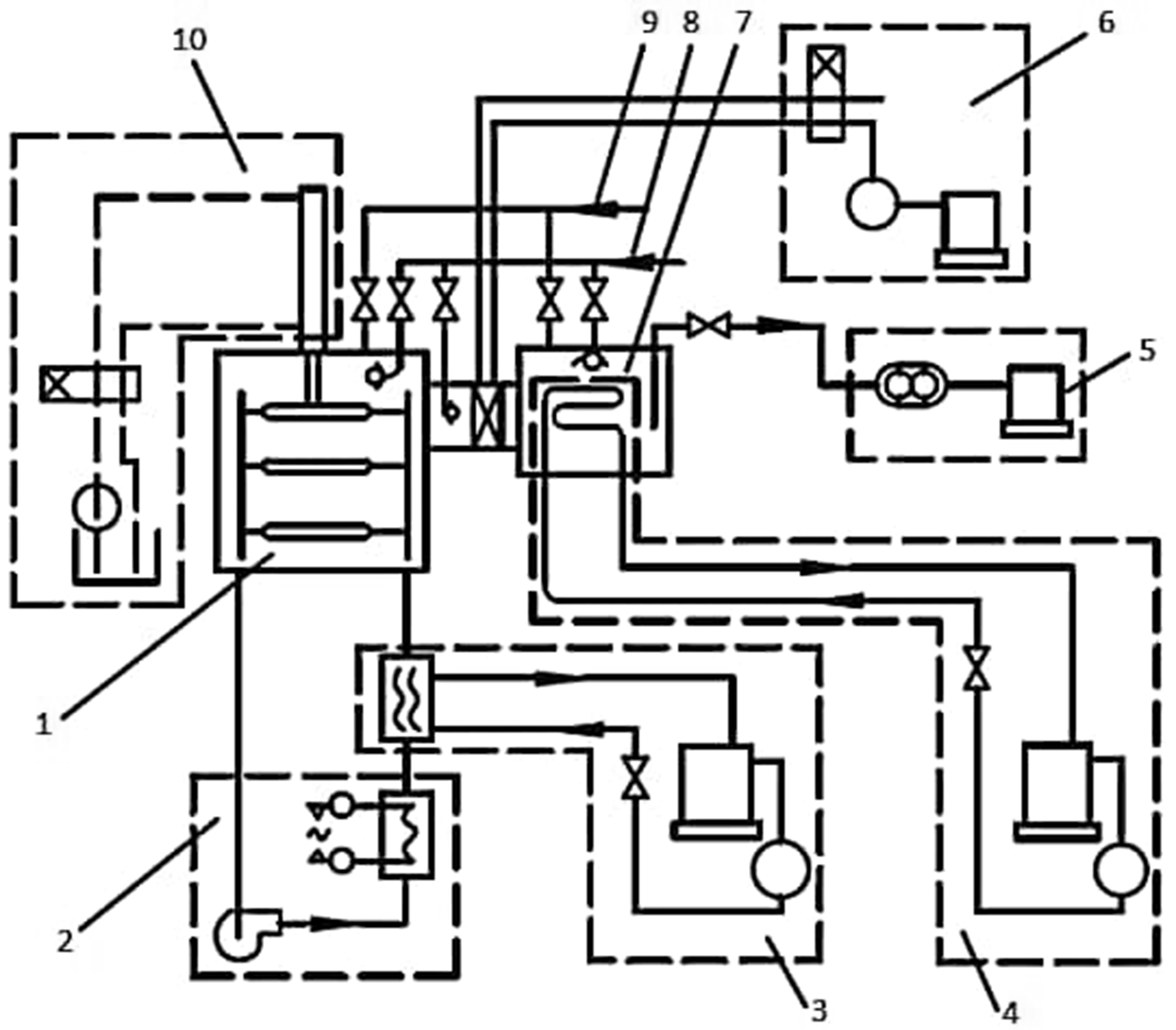
Composition of vacuum freeze-dryer. 1—freeze-drying box; 2—heating system; 3—refrigeration system of freeze-drying box; 4—cold trap refrigeration system; 5—vacuum system; 6—pneumatic system; 7—cold trap; 8—inlet water pipeline of CIP system; 9—inlet steam pipe of SIP system; 10—hydraulic system.
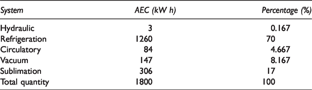
Table 1 shows the percentage of energy consumption of relatively high power system in 20 m2 vacuum freeze-dryer in total energy consumption. It can be known that the largest energy consumption is the refrigeration system, which accounts for about 70% of the total energy consumption. In other words, the research and design of energy conservation and consumption reduction should be carried out from the refrigeration system.
Approximate energy consumption (AEC) of main energy consumption systems of 20 m2 vacuum freeze-dryer.
The strategy of energy-saving improvement in refrigeration system
At present, the refrigeration system commonly used at domestic and abroad is a two-stage compression refrigeration system theoretically composed of refrigeration compressor, condenser, evaporator, thermal expansion valve, pump, and fan (He et al., 2008; Ye et al., 2019). Therefore, the most commonly used method for energy-saving improvement of refrigeration system is to optimize each equipment. For example, when vortex and screw compressors (Wang et al., 2010; Yusha et al., 2017) are used to replace the original piston compressor as the main engine of the refrigeration system, the operating efficiency of the refrigeration system can be increased by about 10%. For condenser (Petitti et al., 2013) and evaporator (Zhang, 2015), replacing with a new type of efficient heat exchanger can improve heat exchange efficiency and reduce energy consumption. The improvement of pump and fan is to change the original fixed frequency into frequency conversion to save energy consumption (Shi et al., 2018; Sinyavsky, 2018). For thermal expansion valves, electronic expansion valves which can be automatically adjusted can also be used to replace them, so as to achieve the purpose of energy-saving (Ataş et al., 2017; He et al., 2018). The energy-saving improvement strategies proposed above for each equipment in the refrigeration system can save energy consumption, but the comprehensive energy-saving effect is not good because of the large time cost and recovery cost of the new equipment. If we can achieve the goal of reducing energy consumption by optimizing the configuration of each system on the basis of not changing the original equipment, it will be a better energy-saving improvement strategy.
Based on this assumption, and aiming at the independent refrigeration system of the freeze-dryer and the workshop, this paper puts forward a freeze-dryer system which combines the solar energy absorption refrigeration with the building. In this system, the solar energy absorption refrigeration system completely replaces the original refrigeration system of the freeze-dryer and the factory building, and refrigerates both the freeze-dryer and the factory building. The system makes the cold energy used step by step and then improves the energy efficiency. Moreover, the main energy supply of solar absorption refrigeration system is solar energy. The effective use of solar energy, a renewable energy, can greatly reduce the consumption of conventional energy, thus playing an energy-saving and environmental protection role. At present, solar absorption refrigeration system is mostly used in building air conditioning refrigeration and gradually applied in industrial refrigeration field, and its market prospects are broad.
A freeze-dryer system for solar absorption refrigeration combined with buildings
This paper presents a freeze-dryer system for solar absorption refrigeration combined with buildings. The energy-saving system has been awarded a patent in China (ZL201820953928.5). The schematic diagram of the system is shown in Figure 2.
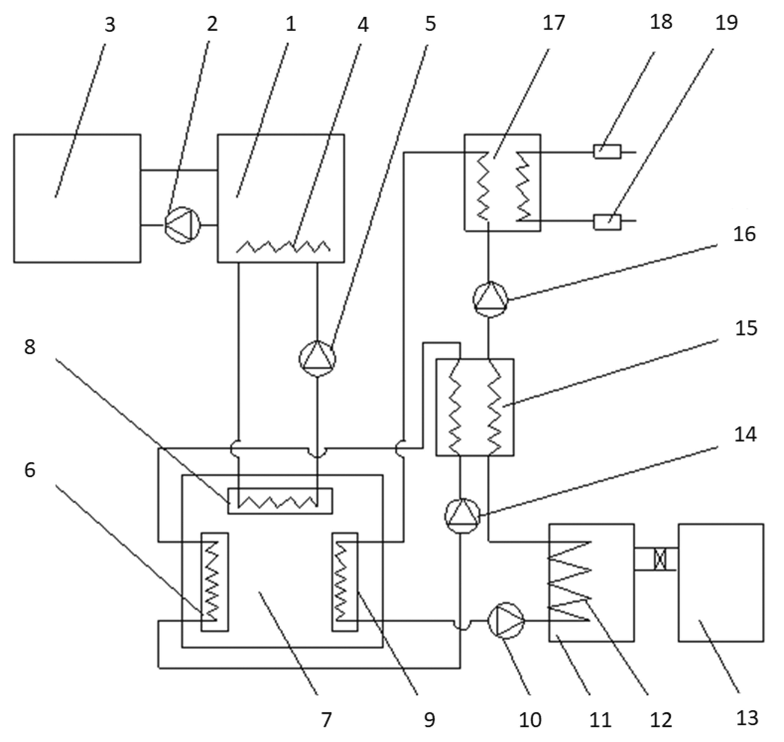
System diagram of freeze-dryer with solar absorption refrigeration in conjunction with buildings. 1—Hot water tank; 2—hot collector circulating pump; 3—solar collector; 4—electric heater; 5—heating circulating pump; 6—absorber; 7—ammonia absorption refrigeration unit; 8—generator; 9—evaporator; 10—cold trap pump; 11—cold trap; 12—cold trap coil; 13—drying box; 14—waste heat pump; 15—waste heat exchanger; 16—refrigeration cycle pump; 17—building air conditioning heat exchanger; 18—water collector; 19—water divider.
System composition
A freeze-dryer system using solar absorption refrigeration in conjunction with buildings is shown in Figure 2. The system consists of five units: solar collector unit, ammonia absorption refrigeration unit, freeze-dryer unit, heat exchange unit, and building air conditioning unit. Each unit is composed of its own components, and each unit contains only the components that play a major role in the operation of the system, so the rest of the components are not displayed in the system. The specific composition of each unit is as follows: solar collector unit consists of hot water tank 1, hot collector circulating pump 2, solar collector 3 and electric heater 4; ammonia absorption refrigeration unit 7 consists of absorber 6, generator 8, and evaporator 9; freeze-dryer unit consists of cold trap 11, cold trap coil 12, and drying box 13; heat exchanger unit consists of waste heat exchanger 15 and building air conditioning heat exchanger 17; building air conditioning unit includes water collector 18 and water divider 19.
Connection modes of system components
The connection mode of each component is as follows: the hot water tank 1 and the solar collector 3 are connected by the collector circulation pipeline, and the collector circulation pipeline is equipped with the hot collector circulation pump 2; the solar collector unit is connected with the generator 8 to provide heat for the ammonia absorption refrigeration unit 7 through the heat exchange with the generator 8; the evaporator 9 and the cold trap coil 12 are connected by the refrigerant circulation pipeline, and the heat transfer between the two is carried out by the cold trap pump 10. The cold side of the waste heat exchanger 15 is connected to the refrigerant circulating pipeline between the cold trap coil 12 and the air conditioning heat exchanger 17 along the direction of refrigerant flow. The heat side of the waste heat exchanger 15 is connected with the absorber 6 through the waste heat exchange circulation pipeline, and the heat exchange is carried out with the help of the waste heat pump 14. The cold side of the building air conditioning heat exchanger 17 is connected with the refrigerant carrying circulation pipeline from the cold trap coil 12 to the evaporator 9. The hot side of the building air conditioning heat exchanger 17 is connected with the water collector 18 and the water divider 19. The refrigeration cycle pump 16 is arranged between the waste heat exchanger 15 and the building air conditioning heat exchanger 17. The whole system realizes the opening and closing of pipeline by controlling the start and stop of each pump.
The ammonia absorption refrigeration unit of this system adopts the conventional ammonia absorption refrigeration machine, as shown in Figure 3, which is composed of generator, distillation tower, condenser, supercooler, evaporator, absorber, ammonia pump, throttle valve, and other components. It is a device that uses ammonia as refrigerant and water as absorbent and obtains cooling capacity by consuming external heat energy. The general principle of refrigeration in this device is as follows: in the generator, the lower concentration of ammonia aqueous solution is heated by external heat source, which evaporates ammonia into ammonia gas; a large amount of ammonia and a small amount of ammonia water from the generator enter the distillation section of the distillation tower for enrichment; after enrichment, ammonia vapor flows into the condenser and is cooled into liquid ammonia in the condenser; liquid ammonia enters into the supercooler. Stepwise cooling, after reducing the pressure by throttling device, enters the evaporator to absorb heat to produce cooling capacity, so as to achieve the effect of refrigeration. In the evaporator, the liquid ammonia after heat absorption becomes gas ammonia and is fed into the absorber; in the initial stage, the dilute ammonia water heated and evaporated in the generator enters the solution heat exchanger, then throttles and reduces the pressure and enters the absorber to absorb the gas ammonia from the evaporator. The concentrated solution produced in the absorber is pressurized by ammonia water pump, heated by heat exchanger, and then re-entered into the generator, so as to circulate refrigeration. The ammonia absorption refrigeration unit 7 in this example is preferably a two-stage ammonia absorption refrigeration unit. The generator 8, the absorber 6, and the evaporator 9 of the ammonia absorption refrigeration unit 7 all contain corresponding two-stage components.
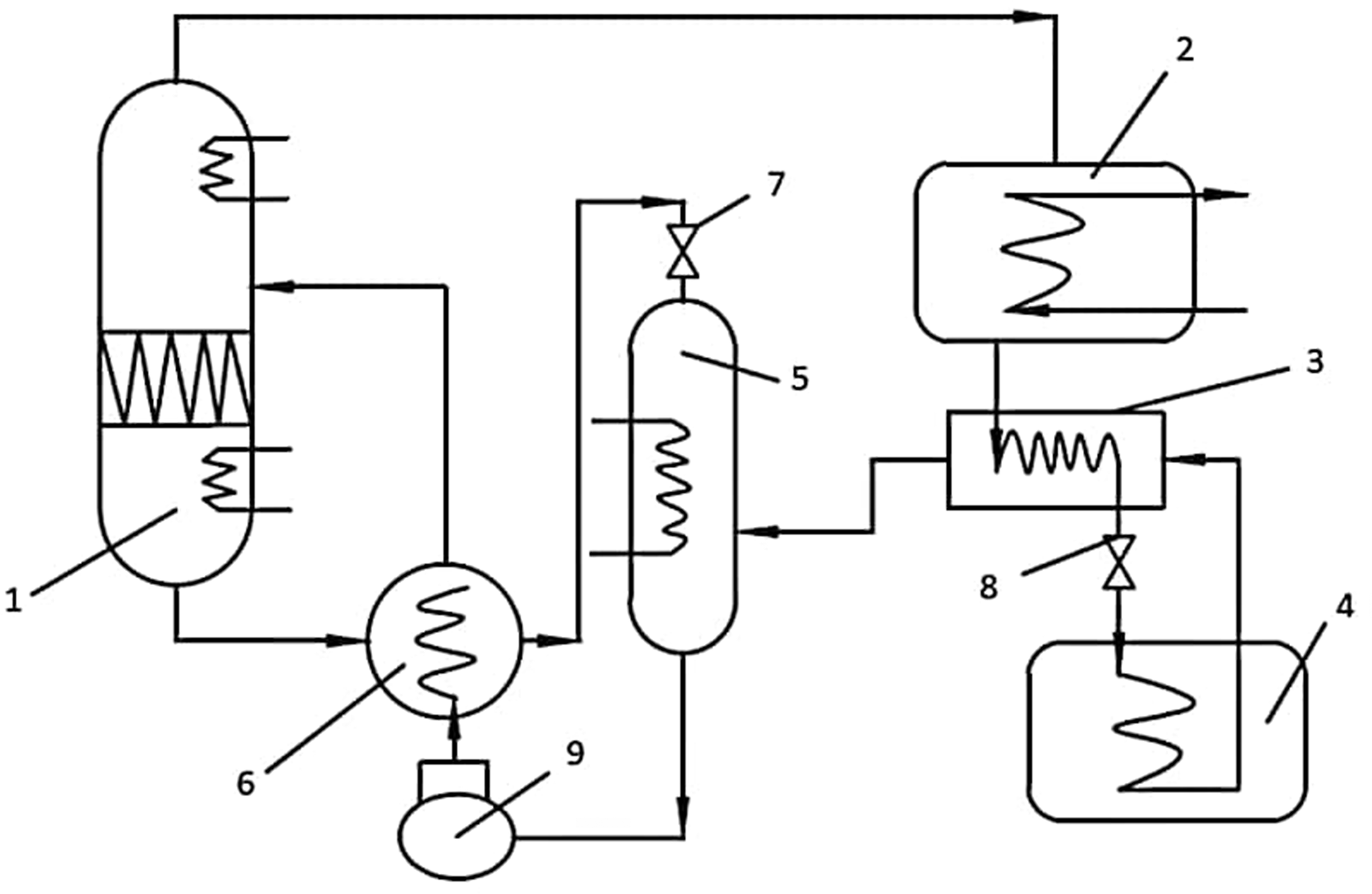
Ammonia absorption refrigeration system. 1—Distillation tower; 2—condenser; 3—supercooler; 4—evaporator; 5—absorber; 6—solution heat exchanger; 7,8—throttle valve; 9—ammonia pump.
Specific operation scheme of the system
The specific operation scheme of the system is as follows:
Solar collector stage: Before the freeze-dryer starts the freeze-drying operation, the water in the hot water tank 1 should be heated to the required temperature. At this time, the hot collector circulating pump 2 is opened, and the cold water in the hot water tank 1 is pumped into the solar collector 3, which is heated by the solar collector 3 and then flows back to the tank 1 to complete a heating cycle. The heating cycle continues until the whole freeze-drying process ends.
Absorption refrigeration stage: When the freeze-drying operation begins, the heating circulating pump 5 is opened, the hot water in the tank 1 enters the generator 8, and the generator is heated. After heat release, the water is pumped back to the tank 1 through the heating circulating pump 5, which completes a heating cycle for the generator. The heating cycle continues, and then drives the ammonia absorption refrigeration unit 7 to refrigerate. When the freeze-dryer is in operation, but the solar collector 3 cannot heat the water to the required temperature due to weather or malfunction, turn on the electric heater 4 for auxiliary heating.
Refrigeration stage of freeze-dryer and building air conditioner:
Freeze-drying machine cooling stage: cold trap pump 10 pumps refrigerant cooled by evaporator 9 into cold trap coil 12, and refrigerates cold trap 11 and drying box 13. Heat transfer stage of waste heat exchanger: the refrigerant released to the cold trap 11 and the drying box 13 flows through the waste heat exchanger 15. At this time, the start and stop of the waste heat pump can be divided into two situations: the first is that when the refrigerant from the freeze-dryer unit is too cold to be used in air conditioning and refrigeration, the waste heat pump 14 is opened and the cooling water heated by the absorber 6 is pumped into the waste heat exchanger 15. The cooled water with relatively high temperature heats the supercooled refrigerant in the waste heat exchanger 15 to the required temperature of air conditioning refrigeration (usually 7–12°C). The second case is that when the refrigerant temperature from the freeze-dryer unit meets the refrigeration temperature of the air conditioner, the waste heat pump 14 is closed, and the refrigerant is pumped directly through the refrigeration cycle pump 16 to the building air conditioning heat exchanger 17. Refrigeration stage of building air conditioning: refrigerant that meets the temperature requirement is pumped to the air conditioning heat exchanger 17 by the refrigeration circulating pump 16. In the air conditioning heat exchanger 17, the refrigerant is used to cool the chilled water from the water collector 18. After heating, the refrigerant is flowed back to the evaporator 9 for the next cycle. The chilled water cooled by the refrigerant is flowed back to the end of the air conditioning unit of the building through the water divider 19 to refrigerate the whole building.
Energy-saving calculation of system
Establishment of Transient System Simulation (TRNSYS) simulation model
In order to analyze the energy-saving of this system, this paper takes a freeze-dryer building in Guangzhou City, China as the research object and uses TRNSYS software to simulate the freeze-dryer building using this system. The freeze-dryer building covers an area of 1177 m2, with a total construction area of 6120 m2. In order to facilitate the establishment of TRNSYS model and load calculation, the freeze-dryer unit is simplified to a room with an area of 75 m2 in the building. The simulation model of the freeze-dryer system using solar energy absorption refrigeration in conjunction with buildings is shown in Figure 4.
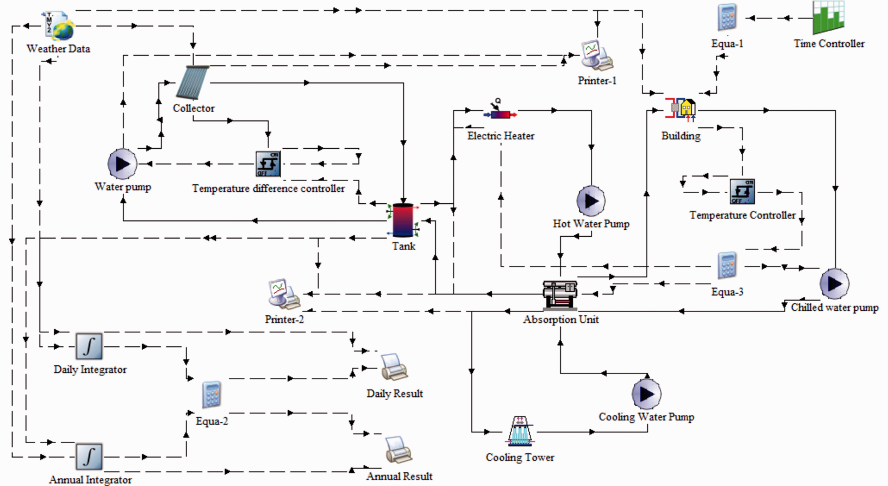
Simulation model of freeze-dryer system with solar absorption refrigeration in combination with buildings.
In the simulation system shown in Figure 4, the rated refrigeration capacity of the absorption refrigeration unit is 314 kW, and the temperature of heat medium water is 80–95°C. The collector uses a vacuum tube collector with a collector area of 412 m2. The volume of the hot water storage tank is 30 m3 and 3 m high, and the heat loss coefficient of the water tank is 0.4 W/(
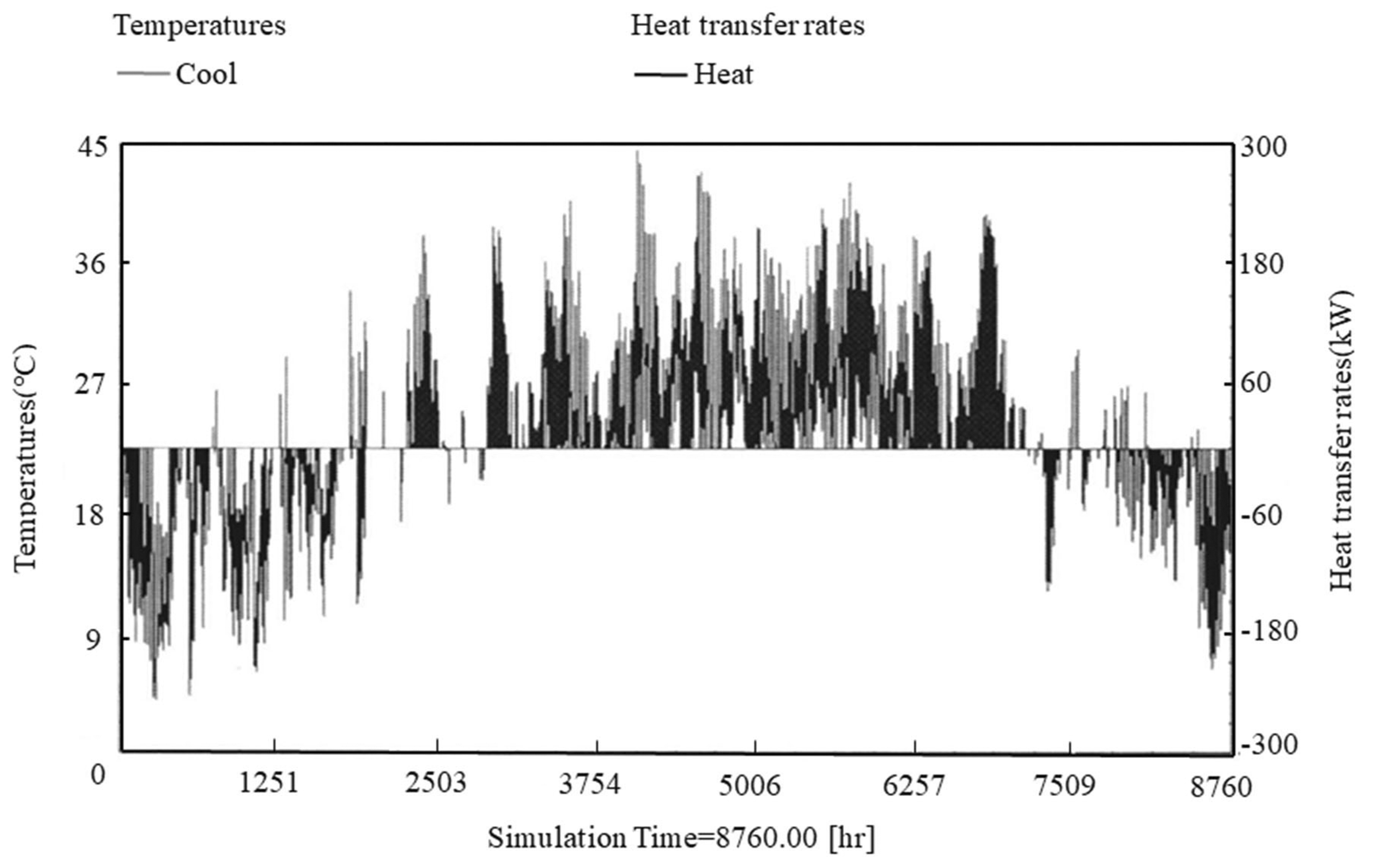
Annual cooling and heating load of the system.
Energy-saving calculation
According to the annual load and the climate characteristics of hot summer and warm winter in Guangzhou, the data of typical month, July and typical day, 28 July, are used for calculation and analysis. The percentage of solar energy in the system load is explained by calculating the solar fraction of the system. The solar fraction is actually equal to the ratio of the useful energy of the collector to the load required by the system. The solar fraction equation is shown in equation (1)
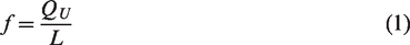
In equation (1), f is the solar fraction (%), L is the load required by the system (W), QU is the useful energy output by the collector in unit time (W) and its calculation formula is as follows

In equation (2), Ap is the area of the heat absorbing plate (m2),
From the data of the solar fraction formula and the simulation model, the solar fraction of July and 28 July can be calculated. The results are shown in Table 2.
Solar fraction for typical month and day.
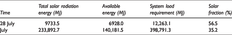
According to Table 2, on a typical day of 28 July, the required load of the whole system is 12,263.1 MJ, and the useful energy output of the collector is 6928.0 MJ, accounting for 56.5% of the total load required by the system. Then, the remaining 43.5% of the required load of the system is provided by the auxiliary electric heater. In the whole July, the solar fraction of the system is 35.2%, the collector output useful energy is 140,181.5 MJ, and the other 64.8% of the system required load is provided by the electric heater. The useful energy output by the collector is the effective solar energy used by the system and also the energy saved by the whole system. First, it is assumed that the energy required for the operation of the original isolated freeze-dryer unit and the building unit is completely from electric energy. Then, compared with the original isolated system, the freeze-dryer system for solar absorption refrigeration combined with buildings can save electric energy 6928.0 MJ in a typical day and 140,181.5 MJ in a typical month. Assuming that the electrical energy comes entirely from coal combustion, the coal consumption can be reduced by about 236.8 kg in a typical day and 4790.9 kg in a typical month. Figure 6 shows the total electric energy, saved electric energy, and saved coal consumption of the system in typical day and month.
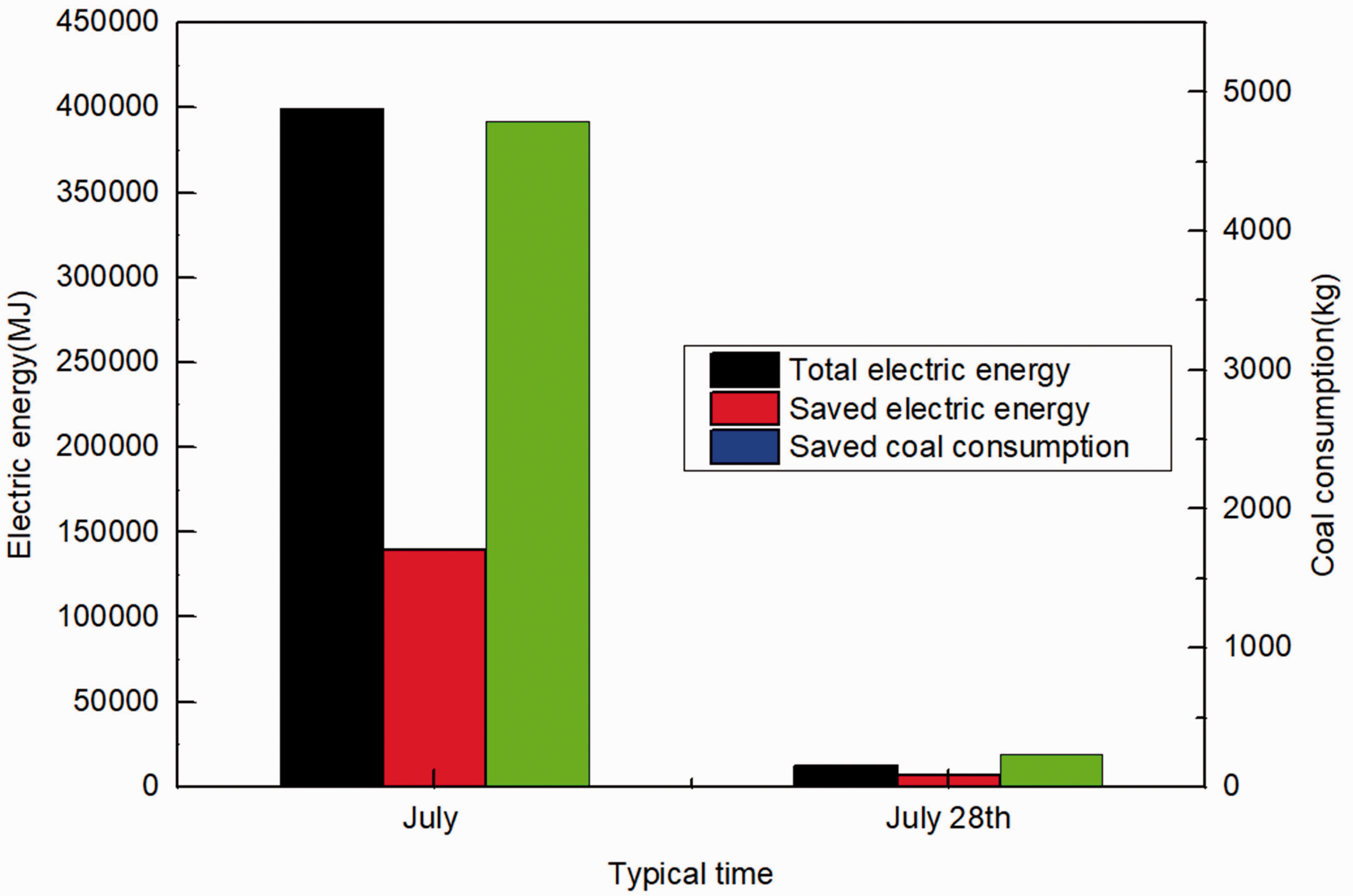
Total electric energy, saved electric energy, and saved coal consumption of the system in typical day and month.
Conclusions
Through the analysis of the energy-saving system of the freeze-dryer which uses solar energy absorption refrigeration in conjunction with buildings, it can be seen that this system has the following advantages:
Compared with the existing technology, the system can not only effectively provide enough cooling capacity for the freeze-dryer, but also use the excess cooling capacity of the freeze-dryer for the clean air conditioning refrigeration of its own plant. The cascade utilization of the cooling capacity makes the energy use more efficient. The whole system is simulated by TRNSYS software, and solar fraction of the system is calculated from the simulated data. From the calculation results, it can be seen that compared with the original freeze-dryer unit and building unit which rely entirely on electric energy, the freeze-dryer system using solar energy absorption refrigeration combined with buildings can save energy remarkably. In a typical day, the solar fraction is 56.5%, which can reduce coal consumption by about 236.8 kg; in a typical month, the solar fraction is 35.2%, which can save coal consumption by about 4790.9 kg. Compared with the conventional system, the energy-saving effect of this system is significant. Through the research of this system, we can guide the existing freeze-drying system and the air conditioning system of the factory building to carry out technical transformation.
Footnotes
Declaration of conflicting interests
The author(s) declared no potential conflicts of interest with respect to the research, authorship, and/or publication of this article.
Funding
The author(s) disclosed receipt of the following financial support for the research, authorship, and/or publication of this article: This paper is supported by National Natural Science Foundation of China (Grant No. 51606116) and Major Scientific and Technological Research Projects of Shanghai Science and Technology Commission (Grant No. 19195810800).