
Abstract
The heterogeneity of a rock mass under high temperature and its thermo-mechanical coupling characteristics are difficult problems to investigate. This situation brings considerable difficulties to the study of underground coal gasification under thermo-mechanical coupling. The development of a numerical simulation method for the thermo-mechanical coupling of heterogeneity rock mass under high-temperature burnt conditions can provide an important foundation for related research. On the basis of the variation of mechanical properties of rock mass with temperature, a thermo-mechanical coupling simulation method, which considers the heterogeneity of a rock mass under high temperature, is proposed in this study. A test block experiment is implemented and then applied to the strata movement and failure of underground coal gasification. The results are as follows: (1) The proposed method can truly reflect the heterogeneity of a rock mass under high-temperature environment, providing an effective method for the numerical simulation of geotechnical engineering in high-temperature conditions. (2) The variation of mechanical properties of rock mass after an increase in temperature is the main reason for the change law of strata movement and failure of underground coal gasification. These factors should be considered in the investigation of underground gasification strata movement and failure. The present study can provide an important means for the research on geotechnical engineering in high-temperature environments.
Keywords
Introduction
In the numerical simulation of geotechnical engineering, rock mass is generally considered homogeneous and isotropic, even if it is disturbed by temperature, but only when the influence of thermal stress is considered (Elahi et al., 2017; Laouafa, 2016; Peter-Borie et al., 2018). However, under high-temperature conditions, not only high-temperature thermal stress will be generated inside the rock mass; the structure and physical–chemical properties of the rock will also be considerably affected by the burning of the rock, thus changing the internal stress distribution and deformation and the failure law of the rock mass. Therefore, a numerical simulation method of thermo-mechanical coupling, which considers high-temperature burnt conditions, needs to be urgently developed.
Underground coal gasification (UCG), as an advanced method of coal chemical mining, has been proposed since the last century. However, although the UCG technology has achieved remarkable progress, its large-scale commercial production is far from ideal (Heinberg and Fridley, 2010; Khadse et al., 2007). The two main reasons for using UCG are as follows: (a) Ensure the regularly controlled combustion of coal in the process of UCG, in which the roof should not collapse in a large area, and the groundwater should not break into the burning surface, i.e. the shape design of the gasifier must be relatively conservative (Jiang et al., 2018). (b) Guarantee the connection between the gasifier and the aquifer, which will cause groundwater pollution, and the connection between the gasifier and the ground surface, which will bring air pollution, indicating that UCG entails environmental risk (Kotyrba and Stańczyk, 2017; Verma et al., 2015). The main reason for these problems is that the main factors that affect the movement and failure of surrounding rocks in a burnt-out zone under high temperature is hard to grasp and control in the design of gasifiers, and this scenario has affected the popularization and application of the UCG technology (Liu et al., 2007; Stuermer et al., 1982; Yang et al., 2008).
Researchers have conducted many studies and achieved fruitful results in ensuring the stability of the gasifier in the UCG process. Elahi et al. (2017) considered the stress change and the deformation of surrounding rocks in a burnt-out area under the condition of thermo-dynamic coupling. They found that various constitutive models lead to different deformations of surrounding rocks. On the basis of elastic foundation beam theory, Xin et al. (2016) established the theory of thermo-elastic foundation beam in UCG under high temperature and analyzed the movement deformation of the roof. Liu (2014) studied roof stability in a gasification channel extension. Shahbazi et al. (2019) considered the change in mechanical properties of rock mass under high temperature and studied the stability of an underground gasification shaft under thermo-mechanical coupling and then proposed a method to solve the problem.
Li et al. (2017) investigated the stability of hyperbolic pillars in UCG under the coupling of high-temperature and in-situ stress. Najafi et al. (2014) established a design method to analyze UCG–pillar stability based on CRIP technology and built a numerical model in FLAC3D to verify the reliability of the method. Tang (2013) investigated the failure law of an overlying strata on a roof in UCG condition. Yang et al. (2014) established a thermo-mechanical coupling model with the ABAQUS finite element software to analyze the temperature field conduction of surrounding rocks and their stress distribution and surface subsidence in a burnt-out zone. Laouafa et al. (2016) adopted the infinite element method to study the influences of the high-temperature effect of surrounding rocks in a burnt-out zone on the movement destruction and surface subsidence of surrounding rocks. Li et al. (2016) compared the different surface subsidence laws caused by UCG mining and conventional strip mining and then proposed the predicating method for UCG mining and subsidence. Mellors et al. (2016) investigated the surface subsidence caused by UCG according to SAR technology. The past studies strongly promoted the development of UCG, but the heterogeneity of rock mass after high-temperature burning was not considered, indicating limitations in the application of their research results.
In this study, a thermo-mechanical coupling numerical simulation method is proposed on the basis of the characterization that the mechanical properties of a rock mass vary dramatically with temperature. The block test results show that the method can reflect the heterogeneity of the rock mass in a high-temperature environment. Our study provides an effective method to numerically simulate geotechnical engineering in high-temperature environments. In the UCG-simulated experiments, we found that the variation of the rock’s mechanical properties after an increase in temperature is the main reason for the change law of movement and failure of the UCG rock strata. These factors should be considered in the study of movement and failure control of UCG rock strata correspondingly. The research results provide an important means to accurately and effectively study geotechnical engineering in high-temperature conditions, and it offers an important reference for the subsequent research of UCG.
Numerical simulation for the thermo-mechanical coupling of high-temperature heterogeneous rock
Methods and procedures
In geotechnical engineering, the change in mechanical properties of materials with temperature is often neglected in the past studies on the numerical simulation of thermo-mechanical coupling. The main reason is that the change in rock mechanical properties with temperature and the propagation of temperature field is extremely complex. This study utilizes FLAC3D as an example to investigate the failure characteristics of the high-temperature heterogeneous rocks. FLAC3D is a finite difference program based on the continuum medium model, and it is widely used in geotechnical engineering.
The numerical simulation method, which considers the thermo-mechanical coupling of high-temperature burnt rock, is implemented in four steps (Figure 1).
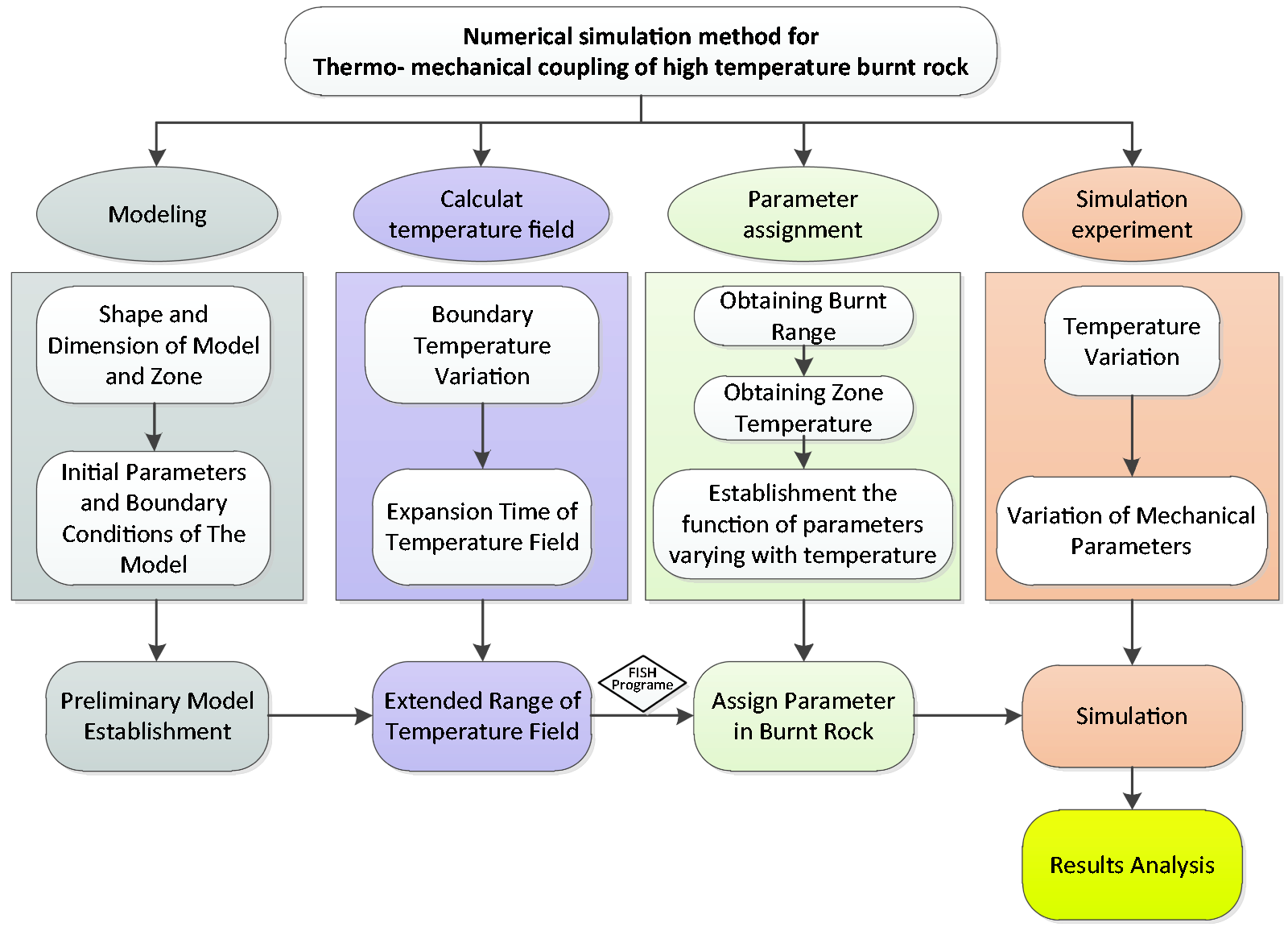
Flow chart of simulation method.
Establish an appropriate model according to the requirements. (a) Determine the shape’s size of each part of the model and the shape’s size of each unit. (b) Determine the initial properties, stress field, temperature field, initial thermodynamic parameters, and boundary conditions of the model.
Calculate the expansion of the internal temperature field in the model. (a) Determine the change law of the boundary temperature. (b) Determine the expansion time of the temperature field. (c) Obtain the expansion range of the internal temperature field in the model.
Assign parameters for the high-temperature burnt rock. (a) Determine the range of high-temperature burning according to the temperature field. (b) Obtain the temperature of each unit. (c) Establish the mathematical model of the mechanical properties that change with temperature. (d) Assign parameters to each unit by using the FISH program.
Adjust the mechanical properties of the rock according to the change in temperature by using the FISH program and carry out mechanical calculation at the same time.
Output the results and perform analysis.
Simulated analysis of test block
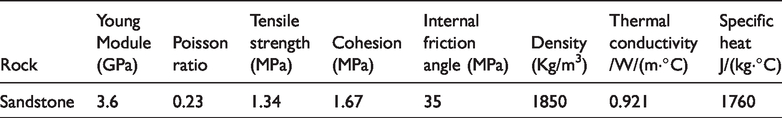
A rectangular test block model with a width of 50 mm and a height 100 mm is established. The model consists of 2000 regular hexahedral elements, and the edge length of each zone is 5 mm. A Mohr–Coulomb model is used as the constitutive model. The initial temperature of the model is 20°C. Loading plates are added to both ends of the model, and the load is placed in fixed speed on top of the model to determine the compressive strength (Figure 2). Sandstone is selected as the model material, and its initial thermal and mechanical properties are shown in Table 1. The variation of mechanical properties of sandstone with temperature is shown in Table 2.
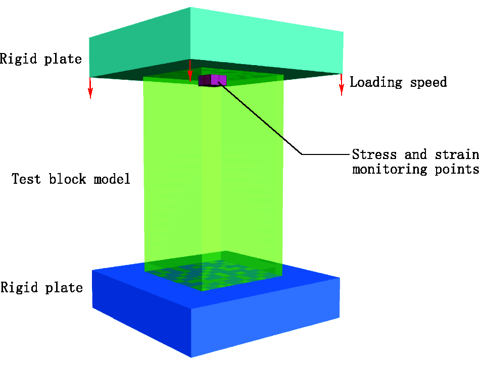
Test block model.
Model properties.
Fitting function of mechanical properties of rock with temperature.
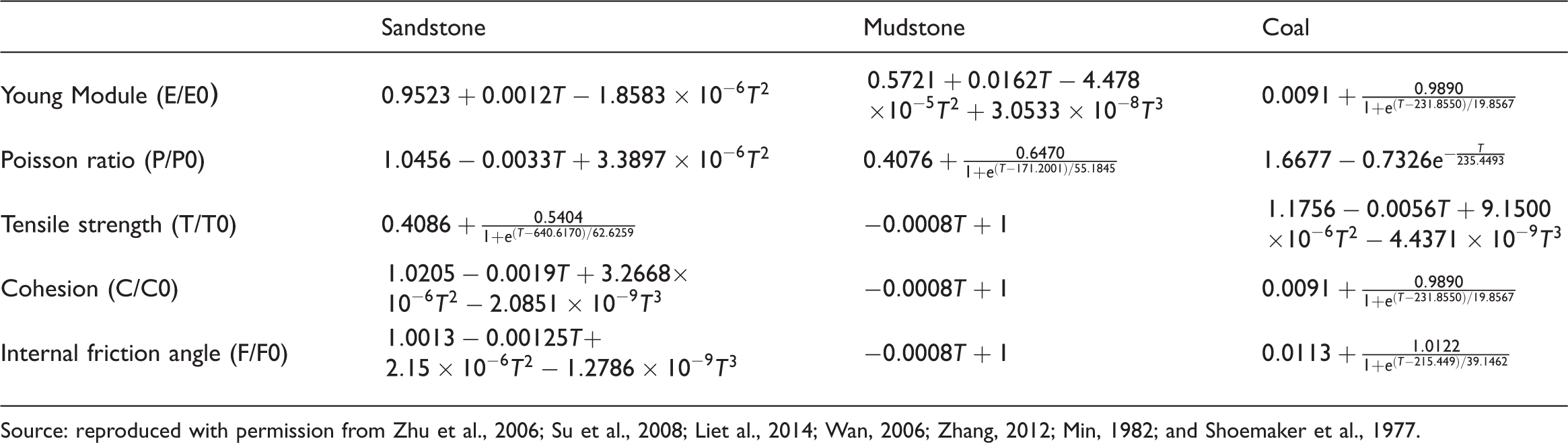
Source: reproduced with permission from Zhu et al., 2006; Su et al., 2008; Liet al., 2014; Wan, 2006; Zhang, 2012; Min, 1982; and Shoemaker et al., 1977.
Before experiencing high temperature, the model was isotropic (Figure 3(a)). A surface heat source of 300°C is applied to the bottom of the model. After heating for 2 h, the temperature field distribution is determined (Figure 3(b)). Given that the variation of rock mechanical properties with temperature is highly complex, parameters cannot be assigned to each unit one by one by using the attachment function built in FLAC3D. Moreover, even if parametric precision is reduced, the efficiency of assigning parameters is extremely low. The FISH program developed in this study can assign parameters to the model based on the non-homogeneous rock mass after an increase in temperature (Figure 3(c)), and thus the three defects of current mainstream simulation software are solved as follows: (a) the limitation involving the number of materials in a single model is overcome; (b) the efficiency of assigning parameters to non-homogeneous materials is increased; and (c) the program can be used to study the orderly/random variation of unit parameters, indicating improved simulation accuracy of non-homogeneous materials.
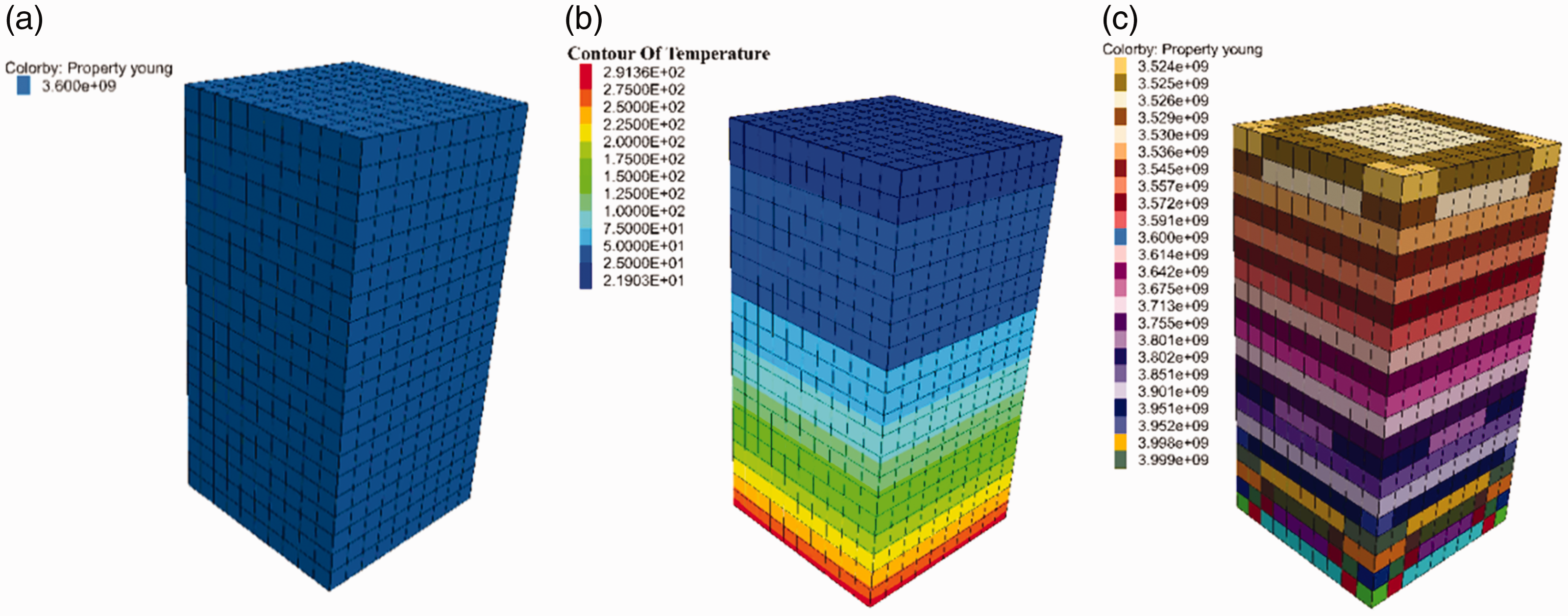
Model property and temperature field distribution. (a) Original model elastic modulus; (b) temperature field distribution; and (c) elastic modulus after high temperature.
Figure 4 shows the variation of internal temperature and mechanical properties with height in the model. The temperature decreases with the increase in height, from ∼300°C to ∼20°C. The mechanical properties also change with height. When the highest temperature drops to room temperature, the properties also change to the initial value. The variation law with temperature is similar to sandstone in Table 2. As shown in Figure 5, the mechanical strength of the model varies considerably under high temperature. At the elastic stage, the stress–strain curves of the specimen at room and high temperatures almost coincide; the reason is that the elastic modulus of sandstone does not change remarkably below 300°C. After entering the plastic stage, the compressive strength of the model decreases from 6.7 to 5.1 MPa. The change can be explained by strength properties, such as cohesion, tensile strength, and internal friction angle, which decrease sharply under high temperature. Thus, the high-temperature burnt state of rocks has a considerable influence on the simulation results.
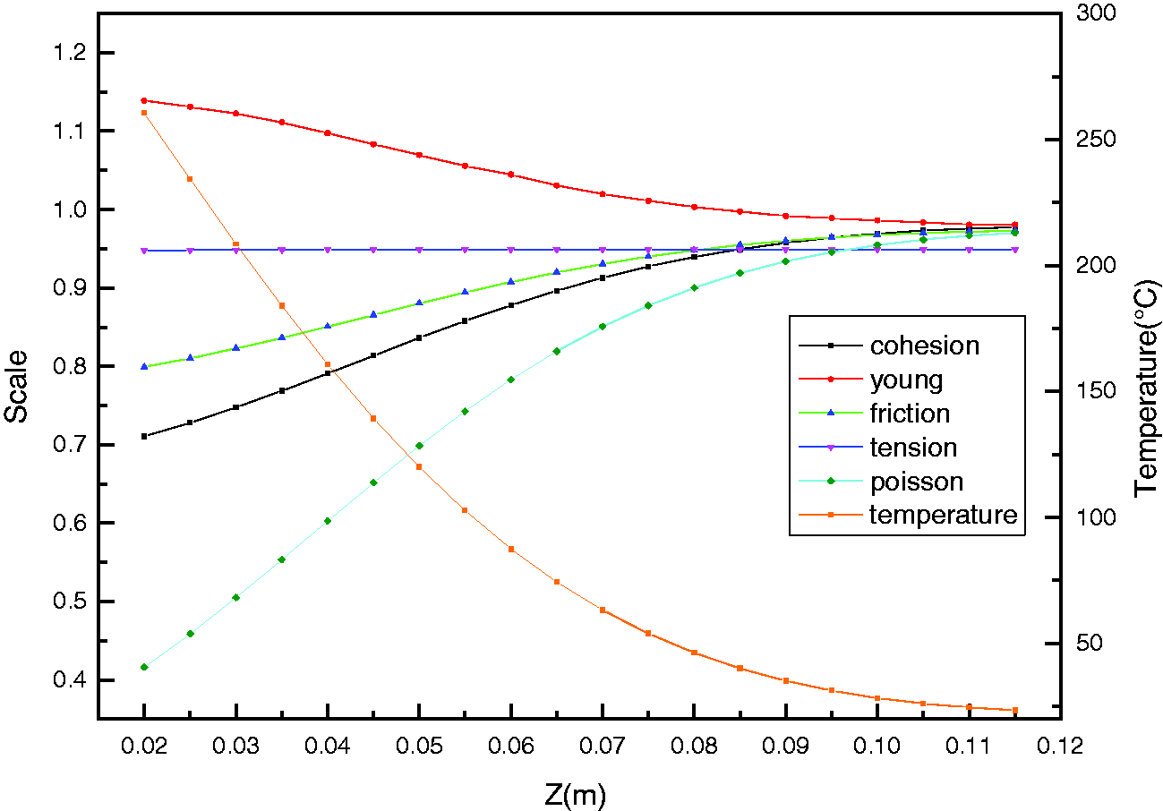
Temperature field and property distribution in Z direction of model.
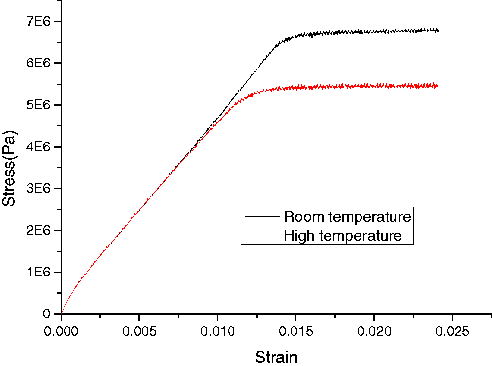
Stress–strain curve of model at room/high temperature.
Given that the mechanical properties of the mesh in the model are based on the average temperature of the mesh, the size of the mesh may affect the strength of the model. In this study, the block models with mesh sizes of 2.5, 3.3, 5, and 10 mm are established, and the compressive strength is studied (Figure 6). The compressive strength of the model decreases with the increase in mesh size. When the mesh size is 2.5 mm, its compressive strength is 5.4 MPa. When the mesh size increases to 10 mm, its compressive strength decreases to 5.0 MPa and is gradually stabilized. The reason is that when grid size is increased, the number of zones forming the test block decreases. As a result, the block tends to be uniform, and its compressive strength tends to be stable.
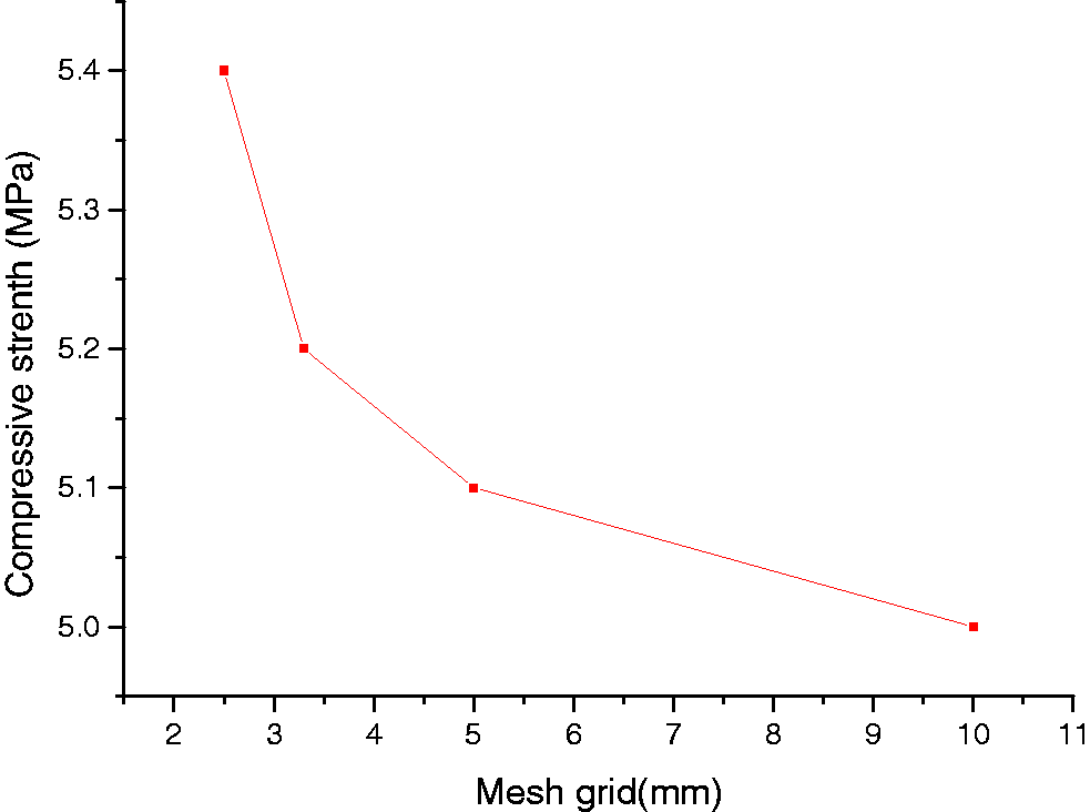
The compressive strength of high temperature heterogeneous model varies with the mesh size.
Case study on UCG
Overview of investigated area
The experimental area is located in Ulanqab at the Inner Mongolia Autonomous Region in China, with geographic coordinates of 113°8′20″ eastern longitude and 41°3′03″ northern latitude. This area is rich in coal. The gasification experiment is performed on the #2 coal seam in the strata of the area allocated for UCG research. Since the ignition experiment on 5 October 2007, a large amount of high-quality gas was obtained, and the experiment was also completed successfully.
Rock mechanics properties under high-temperature
This study summarizes the variations of physical and mechanical properties of sandstone, mudstone, and coal with temperature according to the literature and then establishes the empirical formula of the mechanical properties of rock mass with temperature by regression analysis (Table 2).
Sandstone: According to Figure 7(a), the elastic modulus of sandstone increases, decreases and increases again with the rise in temperature. The maximum value is 1.4 times, and the minimum value is 0.4 times, relative to that at room temperature. Poisson ratio, tensile strength, cohesion, and internal friction angle all decrease with the increase in temperature (Figure 7(a)) (Li et al., 2014; Su et al., 2008; Zhu et al., 2006).
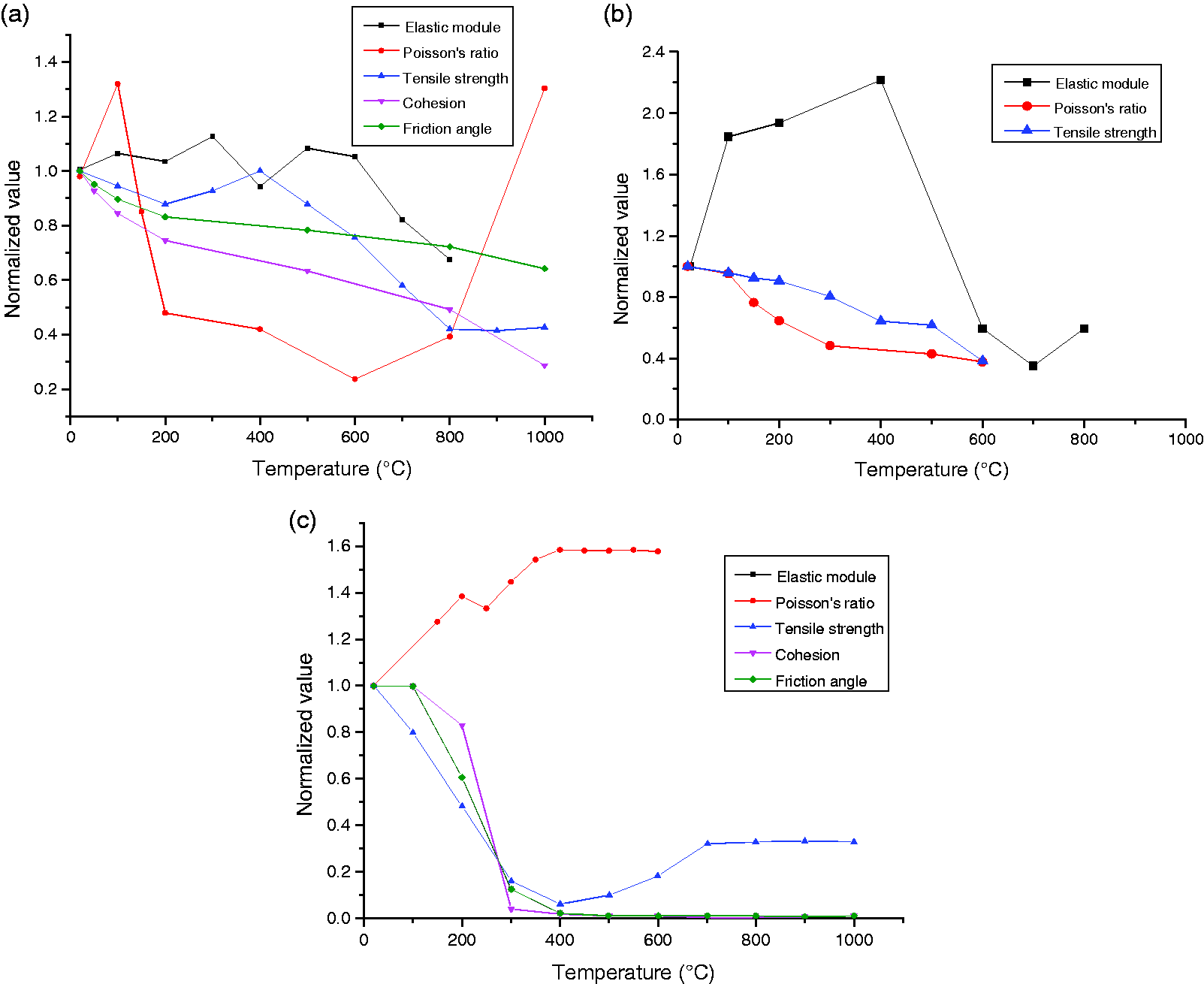
Variation laws on the mechanical properties along with temperature. (a) Sandstone; (b) mudstone; and (c) coal.
Mudstone: Figure 7(b) shows the variation laws of the physical properties of mudstone with temperature. The elastic modulus shows an increasing–decreasing–increasing trend with temperature. The maximum value is 2.2 times, and the minimum value is 0.4 times, relative to that at room temperature. The Poisson ratio of mudstone varies with temperature. When the Poisson ratio decreases gradually from 20°C to 300°C, the minimum value is 0.3 times relative to that at room temperature; afterwards, it becomes consistent. The variation laws of tensile strength, cohesive force, and internal friction angle of mudstone with temperature are similar, i.e. they gradually decrease when the temperature increases (Wan, 2006; Zhang, 2012).
Coal: According to Figure 7(c), the elastic modulus of coal is consistent at temperatures lower than 150°C and drops rapidly beyond 150°C. The elastic modulus of the coal sample drops to ∼1% relative to that at the normal temperature and remains to be consistent beyond 400°C. Tensile strength, cohesion, and internal friction angle also show similar laws. The Passion ratio of coal increases as the temperature increases and is maintained at 1.6 times relative to that at the normal temperature, and then it becomes stable beyond 400°C (Min, 1982; Shoemaker et al., 1977). The isolated coal pillar becomes invalid and loses its bearing capacity beyond 400°C during UCG.
Introduction of gasification technology and process
The experiment adopts the underground gasification technology of “strip mining–surface mining” gasifier with retreating controlling gas injection. The arrangement form of the working surface is similar to that of the strip mining, as shown in Figure 8. In the gasification process, the ignition channel is initially processed, and then the gasification operation is carried out at the first gasification working face. The ignition channel is used as the starting point of gasification and until the end point of the gasification surface is reached. After 90 d, a burnt-out zone with a width of 16 m and a length of 170 m is formed. Each subsequent working face requires 90 d to complete the gasification work, and four burnt-out zones are finally formed when the gasification of the stope is completed.
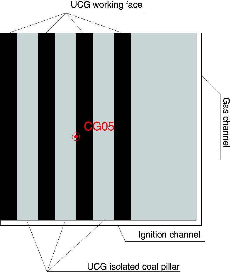
Diagram of gasification working surface arrangement.
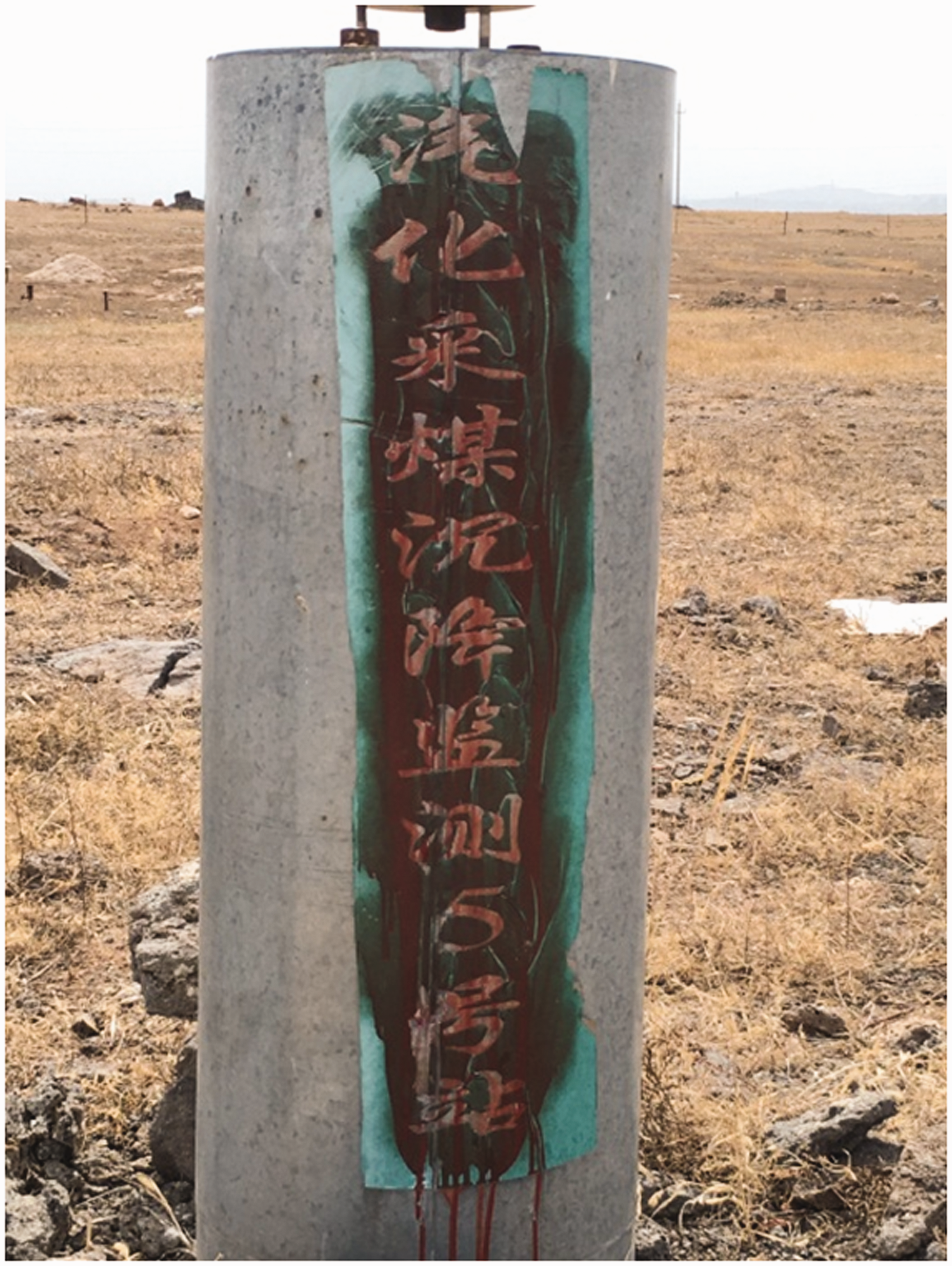
Field measurement
In this study, a high-precision GPS dynamic monitoring point called CG05 is established in the middle of the test area (Figures 8 and 9). The monitoring point is located between the second and third gasification working faces and in the middle of the gasification stope. The surface subsidence measured by the monitoring station likely corresponds to the maximum subsidence. According to the monitoring results, the maximum subsidence of the monitoring point is 36 mm after three months when four gasification surfaces complete the gasification. Thus, gasification does not lead to serious surface subsidence.
Surface subsidence monitoring point of gasification working face.
Model establishment and boundary conditions
The shape of the burnt-out zone after the UCG process is similar to a rectangle (Li et al., 2016). A total of four strips are gasified in the experimental station. The length in the strike direction of the gasification area is 136 m and that in the inclined direction is 170 m. The width of the gasification area is 16 m and that of the isolation coal pillar is 24 m. The goaf modeling method and its corresponding grid size are the same as those of the coal seam. The model excavation is realized by means of the null model. The influence of the model boundary in minimized by establishing a model with a length of 600 m, width of 600 m, and height of 317 m. The floor thickness is 50 m, the coal seam thickness is 5 m, and the roof of the coal seam is 262 m from the surface. The model is composed of regular hexahedrons with grid sizes varying from 2 to 8 m. The model is formed with 28,43,850 nodes and 23,73,750 grids. The grids near the burnt-out zone are fine, whereas those far from the burnt-out zone are rough (Figure 10). Many studies proved that the high-temperature impact of UCG does not exceed 20 m (Li et al., 2018); thus, we only perform thermal coupling calculations in the high-temperature range.
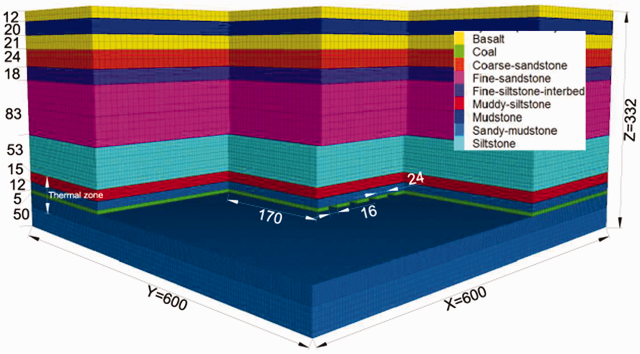
Numerical model dimension diagram.
The Mohr–Coulomb model is applied to the constitutive model of the rock failure. The initial thermo-mechanical properties used to calculate the model’s thermal coupling are shown in Tables 3 and 4. After gasification, the model is parameterized to simulate the heterogeneity of the surrounding rocks in the burnt-out zone. The model of the burnt-out zone is set as the null model to simulate coal seam gasification.
Initial mechanical parameters for the rock mechanics in the strata of experimental area.
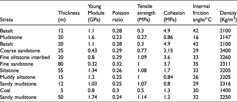
Initial thermo-mechanical parameters for the rock mechanics in the strata of experimental area.
The bottom of the model has a fixed boundary to disallow movement. The top of the model has a free boundary that can move freely in any direction. The boundaries on the two sides in the x and y directions are fixed parallel to the X and Y axes correspondingly, and movement is disallowed. During gasification, the gasified surface temperature is 1400°C and applied to the surface of the burnt-out zone. The initial temperature of the model is 20°C, and the model boundary is adiathermal. After the model is established, the FLAC3D software is imported for the numerical calculation.
Simulation scheme and method
The two main factors of the change in movement law of the strata during the UCG process are (a) thermal stress and (b) the surrounding rock’s thermal burning. Four numerical models are established to analyze the main controlling factors affecting rock movement.
In conventional mining conditions, no heat effect exists in the mining process. The surrounding rocks are affected by thermal stress only in the burnt-out zone. The surrounding rocks are subjected to thermal burning only in the burnt-out zone. The thermal stress is synergistic with the thermal burning of the coal–rock.
Results
Distribution of temperature field around the burnt-out zone
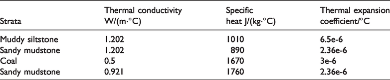
Heat conduction is the main mode of heat transfer in UCG. The heat conduction model of the temperature field in the continuous medium is shown as formula (1). The profile range of the high-temperature influence on the gasifier after simulation for 90 d is shown in Figure 11(a).

Temperature field distribution of surrounding rocks in burning-out area (90 simulated-days). (a) Temperature field distribution and (b) Young’s modulus distribution.
When the temperature field propagates in the rock materials, the closer the temperature is to the original rock temperature, the slower the convergence rate becomes. Here, 20.5°C can be regarded the boundary of the temperature field’s spread range. As shown in Figure 11(a), the propagation range of the temperature field for the floor is ∼8.7 m and that for the roof is 12 m. The variation speed of temperature within the rock gradually decreases as it approaches the burnt-out zone, and the temperature of the roof drops slower than that of the floor. The propagation range of the high temperature of the coal pillars is ∼8.5 m, and the temperature fields are symmetrically distributed on both sides of the coal pillar. Inside the coal pillar, the range in which temperature exceeds 400°C is ∼2.2 m. According to the variation laws of the mechanical properties of coal with temperature, a coal pillar with a propagation range of ∼2.2 m is considered a failure under the influence of high temperature, as it has lost its bearing capacity completely.
Figure 11(b) shows the distribution of the elastic modulus of the surrounding rocks of the burnt-out zone after an increase in temperature. The surrounding rock mass of the burnt-out zone presents high heterogeneity, as well as those of the other mechanical parameters, which are not individually detailed in this paper.
Distribution of vertical stress around the burnt-out zone
The thermal stress generated during UCG and the variation of rock properties have a major influence on the change in internal stress in the surrounding rocks of the burnt-out zone. Taking into account thermal stress and thermal burning, the elastic constitutive model of the internal stress–strain of the stratum is given by formula (2).

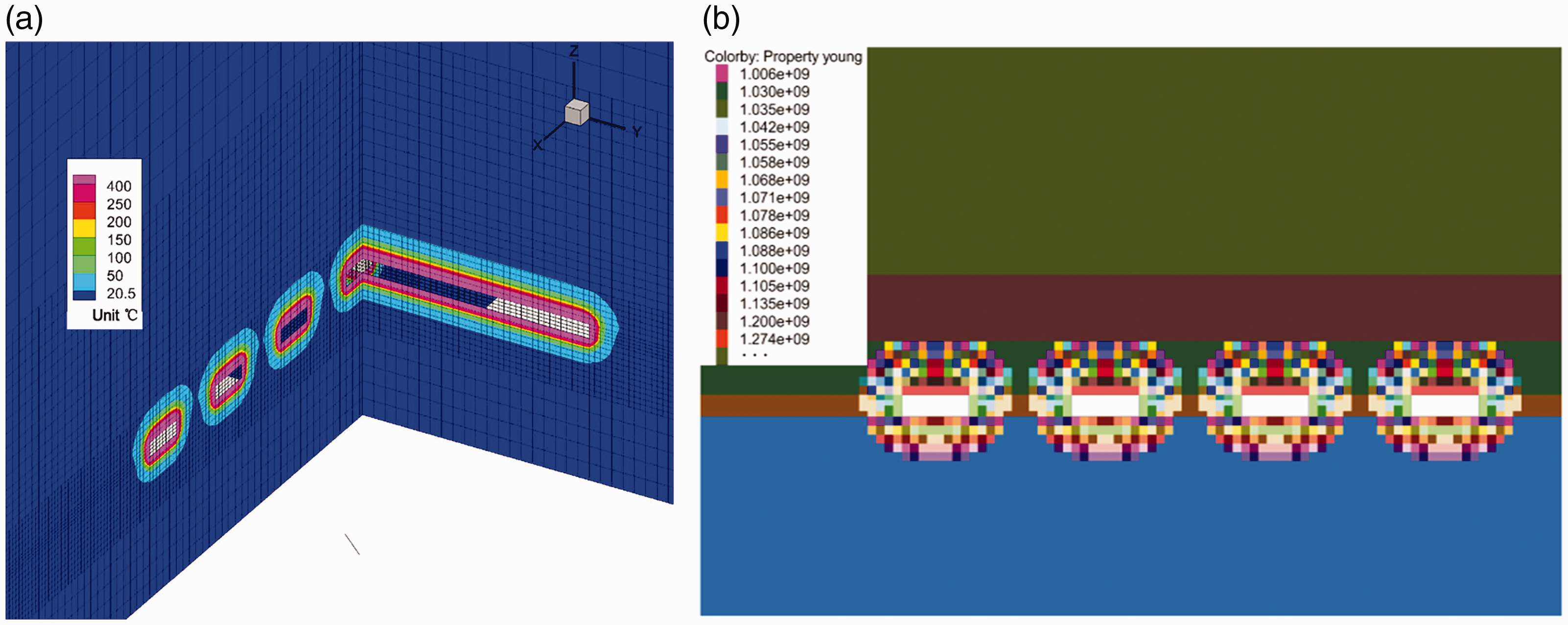
Figure 12 shows the similarities in the vertical stress distributions of the roof, floor, and coal pillar. Stress is concentrated on the coal pillars and the roof and floor on both sides of the coal pillars. The stress extremes near each coal pillar decreases gradually from the middle to the two sides of the mining area; the stress extreme of the coal pillar in the middle of the mining area is the maximum, while the stress extremes on two sides of the coal wall are the minimum. Stress distribution is symmetrical for the coal pillars in the middle of the mining area.
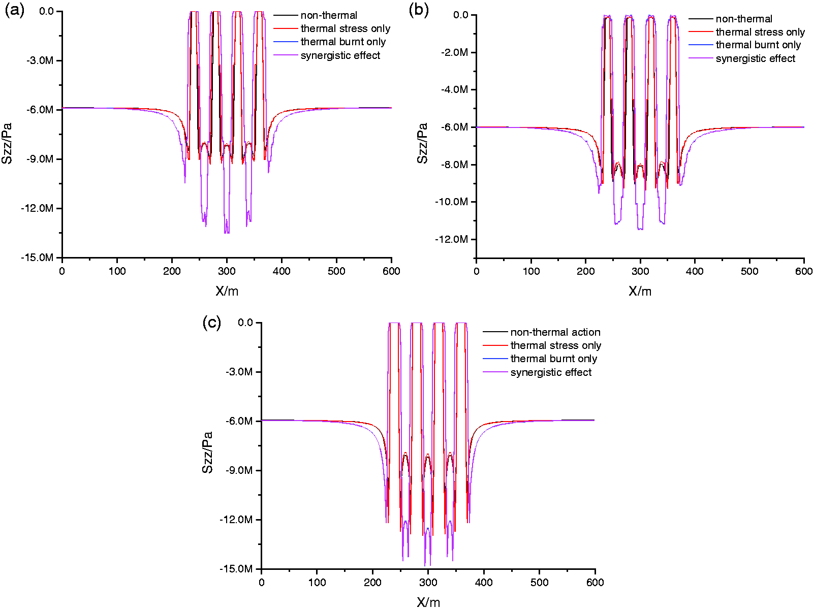
Vertical stress distribution of surrounding rocks in the burning-out area (90 simulated-days). (a) Vertical stress distribution of mined roof; (b) vertical stress distribution of mined floor; and (c) vertical stress distribution of mined coal pillar.
According to Figure 12(a), the vertical stress extreme of the roof is located at the top of the central coal pillars. When the rock is under the collaborative influence of thermal stress and thermal burning, the extreme is −14 MPa. When the rock is under the influence of thermal burning only, the extreme is somewhat similar at −13 MPa. The extreme is −9 MPa without the thermal effect. The vertical stress extreme is slightly increased to −9.3 MPa when the only influence is thermal stress.
Meanwhile, according to Figure 12(b), the vertical stress of the floor is slightly smaller than that of the roof in the overall. The vertical stress extreme under the collaborative effect of thermal stress and thermal burning is the maximum at −11 MPa, which is the same as that under the influence of thermal burning only. The vertical stress is the minimum at −9 MPa without the thermal effect and is slightly increased to −9.3 MPa when under the influence of thermal stress only.
Figure 12(c) shows the vertical stress distribution of the coal pillars. The maximum vertical stress is −15 MPa under the collaborative effect of thermal stress and thermal burning, and the minimum vertical stress is −12 MPa without thermal action. When only affected by thermally burning, the vertical stress of the coal pillar decreases slightly to −14.8 MPa; when only affected by thermal stress, the vertical stress increases slightly to −13 MPa. Additionally, the distribution of vertical stress in the coal pillar increases first and then decreases from both sides to the middle part. The distance between the stress extreme and the coal pillar edge increases gradually from the two sides of the mining area to the middle part of the coal pillar. The distance reaches the maximum of 8 m under the collaborative effect of thermal stress and the thermal burning of surrounding rocks; this scenario is the same as that affected by high-temperature burning only. The distance is the minimum at 2 m without the thermal effect, which is the same as that affected by thermal stress only.
Distribution of plastic regions of coal–rock around the burnt-out zone
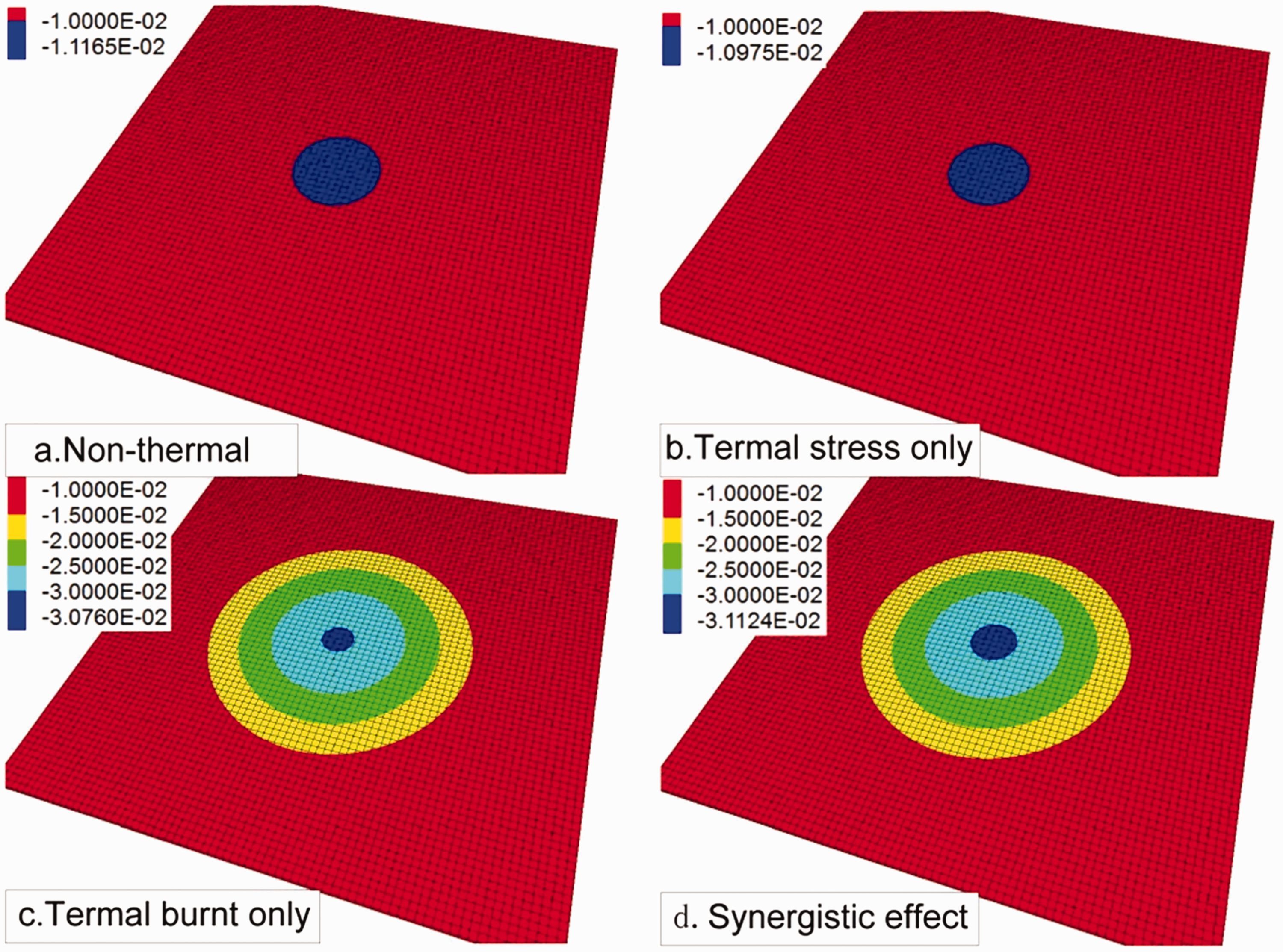
In this simulation, the Mohr–Coulomb failure constitutive model is adopted as the failure criterion of the model. With the thermal burnt state of coal–rock taken into account, the shear failure criterion is as follows

The tensile failure criterion is

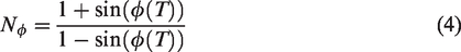
According to Figure 13(a) and (b), the developmental ranges of the areas for the surrounding rock failure of the gasifier are the same under normal temperature and gasification when affected by thermal stress only. The roof failure height is 8 m, and the floor failure height is 4 m. The failure area width of the two sides of the coal pillar is 2 m, and the elastic area of the coal pillars is 20 m. The failure forms of the surrounding rocks under normal temperature are all in the form of shear failure, and a small area of tensile failure appears on the roof and the floor under thermal stress.
Plastic area distribution of surrounding rocks in burning-out area (90 simulated-days).
According to Figure 13(c) and (d), the destructive developmental range of surrounding rocks of the gasifier under thermal burning only is the same as that under the synergistic effect of thermal stress and thermal burning. The roof failure height is 16 m, and the floor failure height is 6 m. The failure area width of the coal pillars on the two sides of the burnt-out zone at the central mining area is 8 m, while the failure area of the coal pillars on the two sides of the burnt-out zone in the marginal mining area is somewhat narrow at 6 m. The width of the elastic area of the central coal pillars is 8 m, and the width of the core area of the coal pillars on both sides is 10 m. The tensile failure ranges of the surrounding rocks in the burnt-out zone under the collaborative effect of thermal stress and thermal burning is higher than those under the action of thermal burning only, and tensile failure areas are observed on the floor.
Distribution of vertical deformation around the burnt-out zone
After the gasification for 90 d, the deformations of the roof, floor, and coal pillars are decreased in general from the middle of the mining area to the two sides. The deformation curves are symmetrical for the coal pillar in the middle of the mining area, and the deformation extreme appears near the middle of the coal pillar.
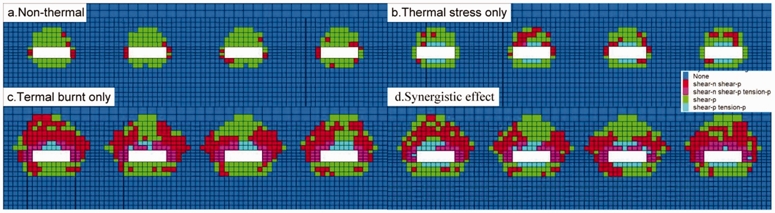
According to Figure 14(a), the subsidence of the roof is mainly concentrated in the burnt-out zone. A certain amount of subsidence is observed in the separated coal pillars and the top roof on both sides of the coal walls, but the amount of subsidence is relatively small. In conventional mining conditions, the maximum subsidence of the roof is 0.13 m, which is only increased slightly to 0.16 m under the action of thermal stress. The maximum value of roof subsidence increases sharply to 0.4 m after coal–rock thermal burning, and that under the synergistic action of thermal stress and thermal burning of the surrounding rocks is 0.46 m.
Vertical deformation of the surrounding rock in burning-out area (90 simulated-days). (a) Vertical deformation distribution of roof; (b) vertical deformation distribution of floor; and (c) compression amount of mined coal pillar.
Figure 14(b) shows the vertical deformation laws of the floor. A slight uplift on the floor occurs at the bottom of the burnt-out zone, whereas the bottom of the coal pillars is in a state of sinking. This phenomenon is due to the stress of the floor that is released after the coal seam is burned, thus enabling the floor rock to rebound and cause a heaving of the floor in the burnt-out zone. Meanwhile, the load of the overlying rock is concentrated under the coal pillar and causes a compression of the floor. The figure also shows that the floor bulge is closely related to thermal stress. The maximum value of the floor bulge is 0.047 m without the thermal effect and increases to 0.062 m under the thermal stress effect only. The floor bulge slightly increases to 0.069 m under thermal burning and then rapidly increases to 0.098 m under the collaborative effect of thermal stress and thermal burning.
According to Figure 14(c), the compression of coal pillars is gradually decreased from the two sides of the coal pillars to the middle part. This phenomenon is attributed to the two damaged sides of the coal pillars, indicating that these parts have lost their bearing capacity, further resulting in a sharp increase in deformation. The compression amount of both sides of the coal pillar is at least 0.037 m in conventional mining conditions, and this value is the same under thermal stress only. When the coal pillar is only subjected to thermal burning, the compression amount of both sides increases sharply to 0.2 m, and the maximum compression amount is 0.22 m under thermal stress and high-temperature burning. The compression amount in the middle of the coal pillars is somewhat small. The minimum compression amount is 0.01 m in conventional mining conditions and under the thermal stress effect only. The compression increases sharply to 0.036 m after the thermal burning of the coal pillars. The compression amount increases to 0.037 m under the collaborative effect of thermal stress and thermal burning.
Subsidence distribution on the surface
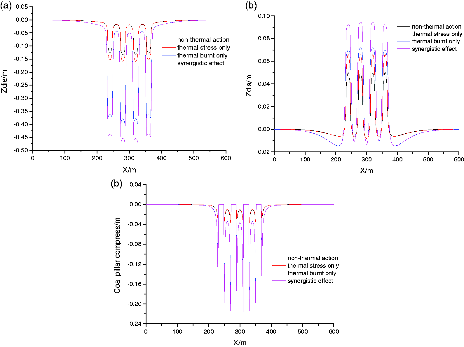
In the process of UCG, the deformation of surrounding rocks in the burnt-out zone is gradually transferred upward and finally subsides on the surface to form a subsidence basin. The subsidence of the surface will not only threaten the safe use of building structures but also cause an ecological degradation on the surface. When the 10 mm surface subsidence is taken as the boundary of the subsidence basin (Figure 15), the maximum surface subsidence is 0.011 m in conventional mining conditions, and the subsidence area is 9432 m2, which is similar to the maximum subsidence at 0.0109 m under thermal stress effect only. At this time, the subsidence area is slightly reduced to 7893 m2. The maximum surface subsidence under the thermally burnt effect of the surrounding rocks in the burnt-out zone is sharply increased to 0.03 m, and the subsidence area is increased to 134,441 m2, which is similar to the maximum subsidence at 0.031 m under the collaborative effect of thermal burning and thermal stress (i.e. the corresponding subsidence area is 137,324 m2). As for the existing UCG process, the UCG has a minimal influence on surface subsidence; considering that the process is expected to improve, the surface subsidence caused by UCG has to be further investigated.
Surface subsidence distribution of underground gasification under different conditions (90 simulated-days).
Discussion
In geotechnical engineering, the heterogeneity of rocks is one of the popular topics in current research. Most especially in high temperatures, the change in mechanical properties of a rock mass causes a change in deformation and a failure mode, and these factors bring challenges to UCG and geothermal resource exploitation. In this study, geotechnical engineering problems are resolved by numerical simulations, and their results are obtained.
Past scholars considered the influence of thermal stress on the stability of gasification channels. Many of them believed that the thermal stress of roofs increases the bending moment and subsequently the threat of roof collapse (Li et al., 2017; Xin et al., 2016). Other scholars considered the change in mechanical properties of rocks under high temperature, but the average value method is often used at a certain range in their calculations, and this approach reduces the accuracy of their calculations. As for the method in this study, each zone in the model is separately assigned with parameters, and the role of thermal stress and high-temperature burning of rocks on the movement of the UCG strata is accurately studied (Najafi et al., 2014; Otto and Kempka, 2015). The simulation results show that the high-temperature denaturation of coals and rocks is the key factor affecting the movement and destruction of the rock strata.
Although certain problems caused by the high-temperature heterogeneity of rocks are discussed in this study, the research results are based on the partial simplification of the model, and its conclusions still have some limitations. In the numerical simulation of geotechnical engineering, the mesh size of the model often has a major impact on the simulation results. Most especially for high-temperature heterogeneous problems, the accurate selection of the mesh determines the correctness of the problem-solving approach. In this study, the minimum mesh of the model near the goaf is 2 m, which has occupied 20 GB of memory and consumed substantial computing time. Therefore, the traditional PC has presented some limitations in the study. With the progress of computer technology, this problem will be solved. The Mohr–Coulomb model in this study is used as the failure model of rocks. However, several studies have proven that the failure mode of a rock mass gradually changes from brittleness to toughness under temperatures exceeding 600°C. These factors should be considered when studying the failure of high-temperature heterogeneous materials. The temperature field in this research is in the range of 2–3 m inside the rock mass and set to rapidly decrease from over 1000°C to ∼400°C. In other words, the problem is partly simplified. In the future, the heterogeneity of a constitutive model for rock mass failure can be studied more effectively. The three main modes of heat diffusion are conduction, convection, and radiation. Many studies have shown that the main form of heat diffusion in the surrounding rocks of UCG is heat conduction. However, with the failure of surrounding rocks, the high-temperature convection of gas should also be taken into account. The results of the current research on the propagation of gas around the surrounding rocks after failure and the thermal convection characteristics of high-temperature gas have yet to be comprehensively determined; such an investigation is not carried out in the present study. From the above analysis, several problems can be solved in the numerical simulation of a high-temperature heterogeneous rock mass. With the deepening of research, the above problems will be the focus of future research.
Conclusions
In high-temperature conditions, not only high-temperature thermal stress is produced in the rock mass, but the mechanical properties of materials are also substantively changed. On the basis of this problem, we establish a numerical simulation method for the thermo-mechanical coupling of a non-homogeneous rock mass under high temperature, thus solving the numerical simulation problem of a high-temperature burnt rock mass. The numerical simulation method is used to study the internal temperature field and the mechanical properties after the expansion of the temperature field. The uniaxial compression test results show that failure strength changes considerably under high temperature. The experimental results are accurate and reasonable, and they prove that the method can be applied to the thermo-mechanical coupling study of a high-temperature non-homogeneous rock mass. The simulation method is applied to the research on the strata movement and the failure of UCG. Strata movement and failure are separately studied under non-thermal action, thermal stress action only, high-temperature burnt action only, and thermal burning and thermal stress synergistic action. Variations of mechanical properties of the rock mass under high temperature are the main reason for the change law of strata movement and failure of UCG.
Footnotes
Declaration of conflicting interests
The author(s) declared no potential conflicts of interest with respect to the research, authorship, and/or publication of this article.
Funding
The author(s) disclosed receipt of the following financial support for the research, authorship, and/or publication of this article: This work was funded by the National Natural Science Foundation of China (Grant No. 51804301), National Natural Science Foundation of China (Grant No. 51674249), Natural Science Foundation of Jiangsu Province (Grant No. BK20180661), and The Open Research Fund of Jiangsu Key Laboratory of Resources and Environmental Information Engineering, CUMT (JS201907).