
Abstract
The shear failure of surface methane capture boreholes (SMCBs) is the main reason for the life cycle shortening of surface methane capture boreholes but lacks a comprehensive lithological analysis. To improve the surface methane capture borehole stability and drainage period efficiency, it is of great importance to investigate the influence of lithology on the shear failure of surface methane capture boreholes. The results of direct shear tests and geological investigations show that the shear displacement increases as the grain size decreases. A jump in mechanical properties occurs at the lithological boundaries and is mainly controlled by the composition of the rock specimens. The change in cohesion is the main possible reason for the step change of the shear strength. High quartz and low clay contents may effectively improve the shear strength and failure resistance of rock. Boreholes may potentially experience preferential casing failure in the section of the weaker mudstone and siltstone due to larger shear displacements and lower shear strengths of those rock types. Protective measures at these sections may improve the stability of the borehole casing. The detection results at the close of the borehole verify the prediction.
Keywords
Introduction
Drilling surface methane capture boreholes (SMCBs) around a coal panel is an effective method of reducing the coal seam gas content (Feng et al., 2016; Karacan, 2015; Yuan, 2016). Longwall retreat is a widely used method of coal mining. Generally, the coal is mined by face retreat, where drivages are made around the edges of the selected panel area, and the face is worked back towards the entry roadway. An SMCB is completed prior to the working face retreat and extracts the coal gas in the area affected by coal mining as the face advances towards and across its location (Sang et al., 2010). Over the past two decades, SMCBs has been a preferred technology to extract methane in major coal-producing countries (Karacan, 2015; Karacan and Warwick, 2019; Liu et al., 2016; Sang et al., 2010). To date, SMCBs have been widely used in many coal fields such as the Huainan, Huaibei, Yangquan, Jincheng and Tiefa coal fields in China (Huang et al., 2017; Sang et al., 2010). However, when a working face passes near an SMCB, the drill hole is likely to be deformed or even damaged, resulting in a significant decrease of gas production, or even a suspended drainage of gas (Figure 1) (Liu et al., 2017b). Approximately 12 of the 22 SMCBs in the Huainan coal field ceased to produce gas due to borehole damage, affecting gas production efficiency (Huang et al., 2010).
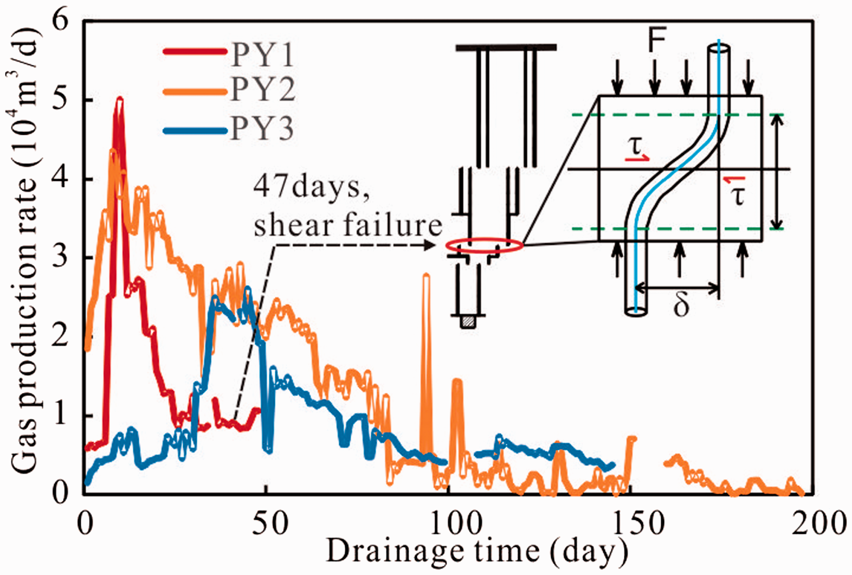
Shear failure of methane capture borehole (τ, horizontal shear stress; δ, shear displacement; d, shear field).
Well stability is considered a critical issue in the oil and gas industry. A lack of well stability has led to low production and significant implications in terms of the costs, safety and environmental issues. To reduce the probability of borehole failure, previous studies on borehole failure mainly focused on the evaluation of drilling design, including borehole construction and trajectory, casing material and drilling fluid, generally assumed that rock materials are isotropic and linear elastic in deformability and strength (Bradely, 1979; Kiran et al., 2017), and extended the analysis of the homogeneous or anisotropic strength (Ajalloeian and Lashkaripour, 2000; Lee et al., 2012; Mohammed et al., 2019; Périé, 1990; Tien et al., 2006) and geostress of the lithology (Song, 1998; Yan et al., 2017). The chemical–mechanical or physical–mechanical interactions between drilling fluids and clay minerals as well as groundwater also affect drilling damage (Haimson and Song, 1993; Liang et al., 2015; Zeynali, 2012), but these effects may be applied to improve drilling methods and maximize the effectiveness of drilling (Bennion et al., 1996; Clancey et al., 2007).
Despite the recent progress in the stability of drilling wells, few scholars have analyzed stability by considering the overlying strata movement due to removal of large panels (Liang et al., 2014). One reason for this trend is that the importance of unconventional gas reservoirs has only recently become an important issue (Saurabh et al., 2016; Wang et al., 2014). However, the stability estimation of boreholes through the overlying strata plays an important role in improving borehole performance. Some papers suggest that factors, including the coal seam burial depth, mining-induced stress, coal pillar dimensions, and relative position of the borehole and coal face, should be considered during borehole stability analysis (Liang et al., 2017a; Schatzel et al., 2012; Scovazzo and Russell, 2013; Shang et al., 2019). Researchers have conducted many studies on the coal mining factors (Xu et al., 2011a; Zhang, 2012), geological conditions of the overburden (Diwan et al., 2011; Flores et al., 2019), failure modes of the mining strata in which the boreholes are drilled (Chen et al., 2012; Zheng et al., 2019), shear failure via applying shear stress on the well material (Davies et al., 2014; Mansourizadeh et al., 2016) and prediction of the stability of a well during the extraction of an active coal working face via computational modeling (Chen et al., 2012; Liu et al., 2017a; Qin et al., 2015; Whittles et al., 2007). Three typical failure modes of a borehole casing were classified, and tensile and shear failure were thought to be the most common failure modes (Chen et al., 2012; Sun, 2008).
In addition, the deformation and movement of strata caused by coal mining is a dynamic mechanical process that propagates upwards (Karacan, 2015; Karacan and Warwick, 2019; Palchik, 2003; Schatzel et al., 2012). Other investigations have defined and then investigated the effect of topography and the sequential extraction of coal faces on both sides of well-protecting coal pillars as the important factors influencing the stability of SMCB through mineable coal seams (Liang et al., 2014, 2017a; Shang et al., 2019). Coal measure strata are usually composed of numerous bedded sedimentary formations of varying thickness, strength and stiffness. Therefore, apart from the topographical condition, the strata sequences, the Lithology-controlled performance and the presence of weak interfaces between alternating soft and stiff layers (Ghazvinian et al., 2010; Liang et al., 2017b; Liang et al., 2014; Lu et al., 2016; Majdi et al., 2012; Palchik, 2003; Whittles et al., 2006; Xu et al., 2011b), which have not aroused adequate attention, also significantly affect the deformation and movement of the overburden and the resulting failure and performance of SMCBs, which traverse the overlying strata (Karacan, 2009; Liang et al., 2017b; Liu et al., 2017b; Xu et al., 2011a; Zhai et al., 2015).
Due to the variation in formation lithology, the acting force and shear displacement applied to the borehole are obviously different. Despite recent contributions, there have been few studies on the impact of lithology on shear failure for SMCB-traversed mined coal seams due to experimental difficulties with overlying strata movement and shear displacement in geological conditions. Accordingly, in this paper, direct shear tests of rock specimens were performed to obtain the influence of shear stress on shear displacement to closely examine the performances of different lithologies in terms of shear failure. Moreover, abundant mechanical parameters are used to justify the results obtained using the direct shear method and determine the effect of the lithology of the overlying strata on the possible shear location of the borehole. Therefore, we use this analysis to predict possible locations, penetrated by boreholes, that are prone to damage or, more specifically, failure by lithological shear offset.
Experiments and methods
Specimen preparation
For the shear tests, the rock specimens were taken from coal-bearing strata in a borehole in the Huainan mining area, Anhui Province, China. To better understand the shear strength of different lithologies, the utilized specimens include coarse-grained sandstone, medium-grained sandstone, fine-grained sandstone, siltstone and mudstone, which are the most representative natural lithology types, without obvious macroscopic cracks. In addition, it is difficult to collect core samples without structural planes to define their true mechanical parameters through experiments. Thus, only 25 specimens in five groups were tested using a direct shearing machine.
These core samples were properly packed and then sent to the laboratory immediately after classification and packing. During the sample preparation process, core samples (with a diameter of 50 mm) were prepared for cutting at an aspect ratio of 1:1 in accordance with GB/T 50266-2013. After cutting, each surface of all the samples was ground to ensure a flat surface. Figure 2 presents parts of specimens before and after the direct shear tests, and apparent shear failure planes were observed in the middle of the specimens after the tests were completed. The sample numbers shown in Table 1 are defined as follows: the first digit indicates the rock lithology, and the second digit indicates the number of specimens in that group.
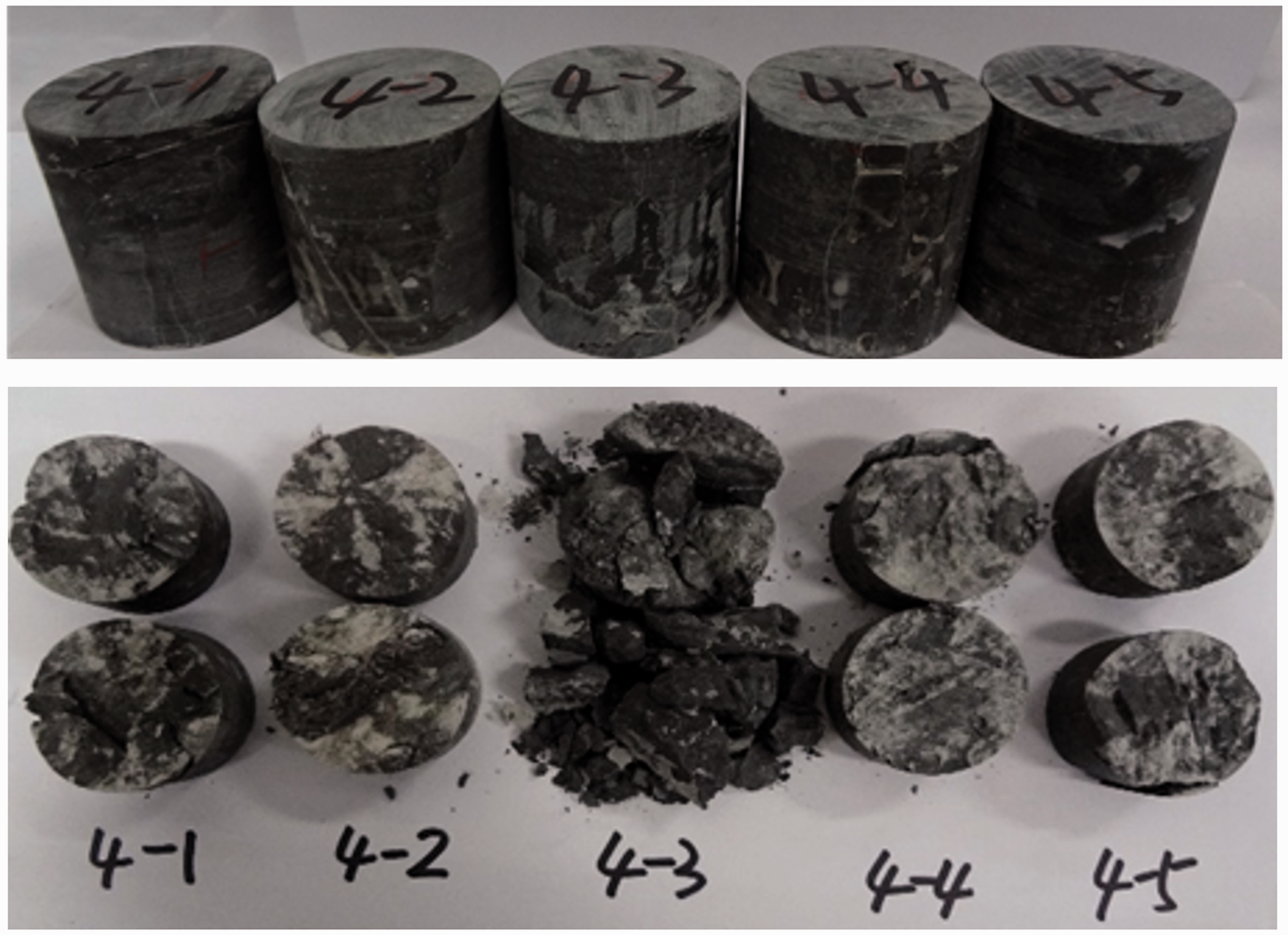
Parts of specimens before and after direct shear tests.
Direct shear testing results for rock specimens.
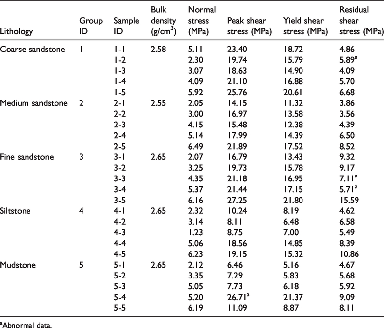
aAbnormal data.
Tests apparatus
In this study, direct shear tests on core specimens were performed using a multi-functional testing machine. The purpose of this test was to examine the horizontal displacement of a lithology as a function of the shear stress applied to the sheared plane. The shear failure location of an SMCB is possibly influenced by lithology. It has been suggested by Brady (2006) and Rosso (1976) that although the results of the triaxial shear test are more accurate than those of the direct shear test, there is a systematic relationship between the results of these two test methods. Moreover, the direct shear test was used to obtain a basic rule rather than applying the data to practical engineering. Hence, for this paper, the data error from the direct shear test has no obvious influence on the acquisition of the shear law. Compared with the more accurate measurements collected by triaxial testing, the measurements collected by the direct shear apparatus were thought to be able to give a definite rule similar to that from the triaxial data. The obtained group of data cannot obtain the true values under the formation conditions, but the tested errors are clearly at a more tolerable level. Therefore, the direct shear apparatus in this paper was adequate regarding the expected results of shear behavior considering lithological aspects.
Figure 3 shows the direct shear test apparatus used to examine the failure behavior of lithology. Two hydraulic jacks controlled by pressure oil pumps are fixed on the top and right sides of the stiff loading frame. The maximum loads provided by the two hydraulic jacks are 294 kN and 490 kN, with an oil cylinder maximum trip of 60 mm, respectively. The equipment has lower and upper shear boxes and one row of ball bearings. The lower shear box is fixed, and the upper shear box can undergo dislocation. The upper and lower shear rings are placed in the inner hole of the shear boxes, and these boxes have four ground steel surfaces. An appropriate size and shape of the shear rings are designed in Figure 3(d).
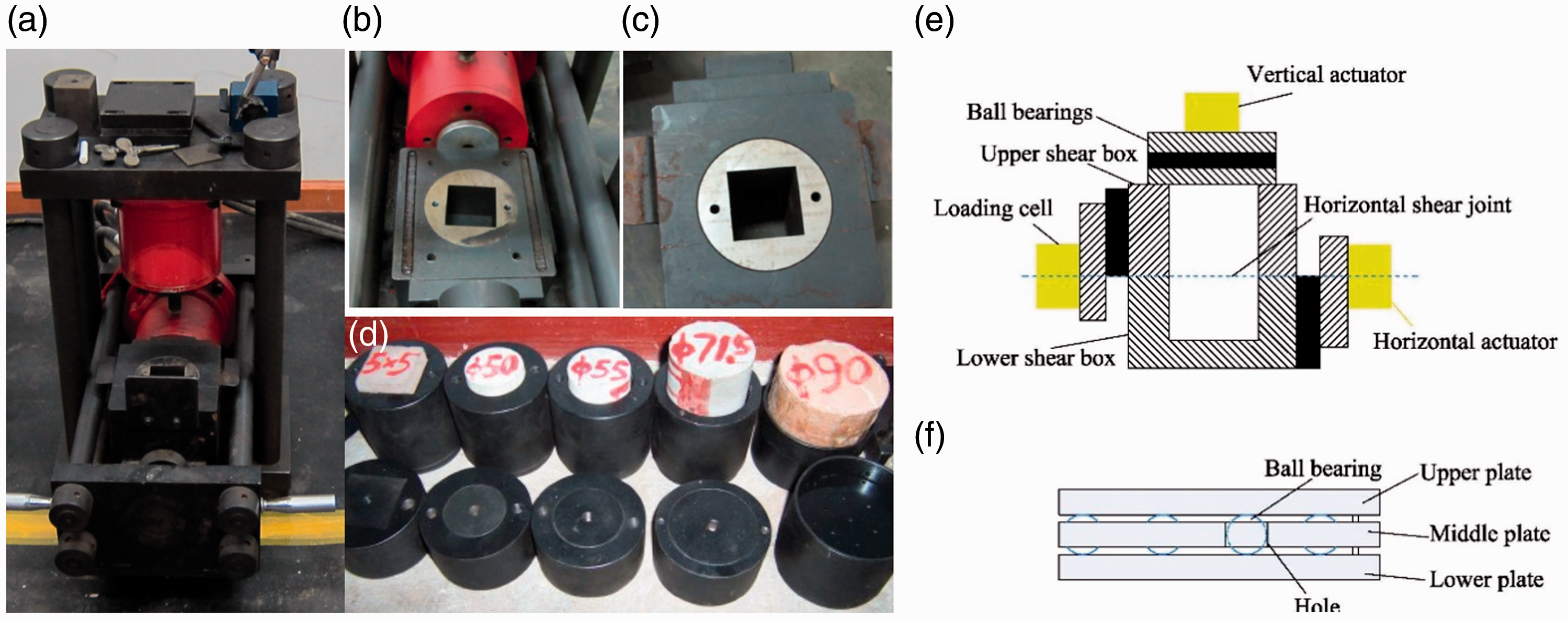
Test system of specimen in direct shear test: (a) direct shear test apparatus; (b) lower shear box; (c) upper shear box; (d) shear rings; (e) experimental device; (f) ball bearings.
Measured data from eight channels can be collected simultaneously. The sensors and the other instruments were calibrated, as required, before each sample was tested. The ranges of the pressure sensor and displacement are 0–40 MPa and 0–50 mm, with a resolution of 0.01 MPa and 0.01 mm, respectively.
Test procedure
In this study, the testing procedure followed the Chinese standard GB/T50266-2013. The five specimens in each group were subjected to normal stresses of 2, 3, 4, 5 and 6 MPa. In the direct shear test, the usual test procedure requires the application of a constant normal load (CNL), and the horizontal load gradually increases until sliding occurs. The test process includes two main steps: (1) the initial normal stress is loaded to the desired value at a loading rate of 0.08 kN/s; (2) shear stress was applied at a constant shear speed of 0.2 mm/min until the specimen was destroyed. In the process of direct shear testing, the rock will dilate when it is destroyed; thus, the normal stress applied in the test may be inconsistent with the predetermined normal stress. Throughout these tests, the loads and shear displacements in the normal and shear directions were recorded automatically by a computer.
Estimating method of shear strength
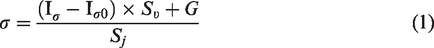
The volume of the standard specimen was calculated by measuring the cross-sectional area and height of the specimen, and then the mass of the specimen was weighed. The density of the rock block can be obtained by using the relationship between volume and quality. The normal stress and shear stress are, respectively, calculated by the following equations
The Mohr–Coulomb criterion (equation (3)) is used to express the relationship between the peak and residual shear strengths and normal stress, as shown in Figure 4, according to the given friction angle and cohesion

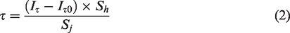
Shear stress–shear displacement curves of rock specimens under different normal forces.
The experimental data applied in this study, such as Poisson’s ratio, elasticity modulus, tensile strength, friction angle and cohesion, were collected from the test results and measurements of the core samples. Microscopic examinations were conducted for petrographic analysis with a polarizing microscope and a scanning electron microscope (SEM) equipped with a ZEISS Sigma system.
Results and discussion
Shear failure characteristics
Peak and residual tests of each specimen were carried out according to the test procedure. The residual shear strength parameters are estimated by the residual state test. The results of all the direct shear tests on the rock specimens are summarized in Table 1.
All of these tests were conducted in accordance with national standards and related specifications and performed at a qualified laboratory, and no abnormal conditions were examined during the measurements. Although the experiments were carried out carefully according to specific methods, some tested parameters were of poor quality and omitted due to the heterogeneity of the rocks, such as specimens 1-2, 3-3, 3-4 and 5-4, as shown in Table 1. Regarding the low values of residual shear stress obtained from specimens 3-3 and 3-4 in Group 3, the shear stress was perhaps influenced by the microcracks that pass through the shear plane or the concentrated distribution of some minerals with low strength (McBeck et al., 2019; Tavallali and Vervoort, 2010), but these microcracks or minerals were not detected. The shear plane is generally rough, with some asperities. If a small number of high-strength particles, such as quartz, are present on the shear plane or inclined plane, the shear process will encounter resistance and increase the shear strength anomalously. For example, the peak shear stress of mudstone sample 5-4 exceeds the maximum peak shear stress of the coarse-grained sandstone samples. For these reasons, it is unlikely that these abnormal data are caused by measurement errors or unrealistic stress applications. Regardless of the reasons, these data do not distort the Lithology-controlled performance, which is the focus of the present analysis.
Relational graphs of shear displacement versus shear stress were plotted for each specimen. As illustrated in Figure 4, all curves have a similar trend: the shear stress level dropped to a residual state after the peak strength. The shear displacement of most specimens increases with increasing shear stress, resulting in a large slope. After the shear stress reaches a peak strength, the shear stress decreases as the shear displacement increases. However, some specimens, such as specimens 3-2 and 4-3, show an increase of shear displacement with increasing shear stress at the initial stage. This may be related to the heterogeneity of the samples or their different compositions and microstructures. Compared with samples with coarse grains, once loaded by the concentrated stress, these two samples that possibly contain smaller particles with more clay minerals will dissipate more permanent deformation energy and accumulate less elastic strain energy during elastic deformation. The potential possibility of shear displacement under the same shear stress condition thus increases.
The shear curve increases significantly after the shear displacement reaches a certain value (approximately less than 0.5 mm to 1.0 mm) until the peak stress is reached, and a change in shear stress occurs at the peak. The slope of the curve clearly changes from positive to negative, indicating obvious brittle failure characteristics of the lithological specimens with a decrease in cohesion. As the displacement continues, the shear stress decreases to a certain residual value, and then the residual value remains stable, even with increasing shear displacement. The residual stress varies greatly and is generally approximately 21%–78% of the peak stress. This indicates that the specimen has been destroyed but still has a certain load-carrying capacity under an external force.
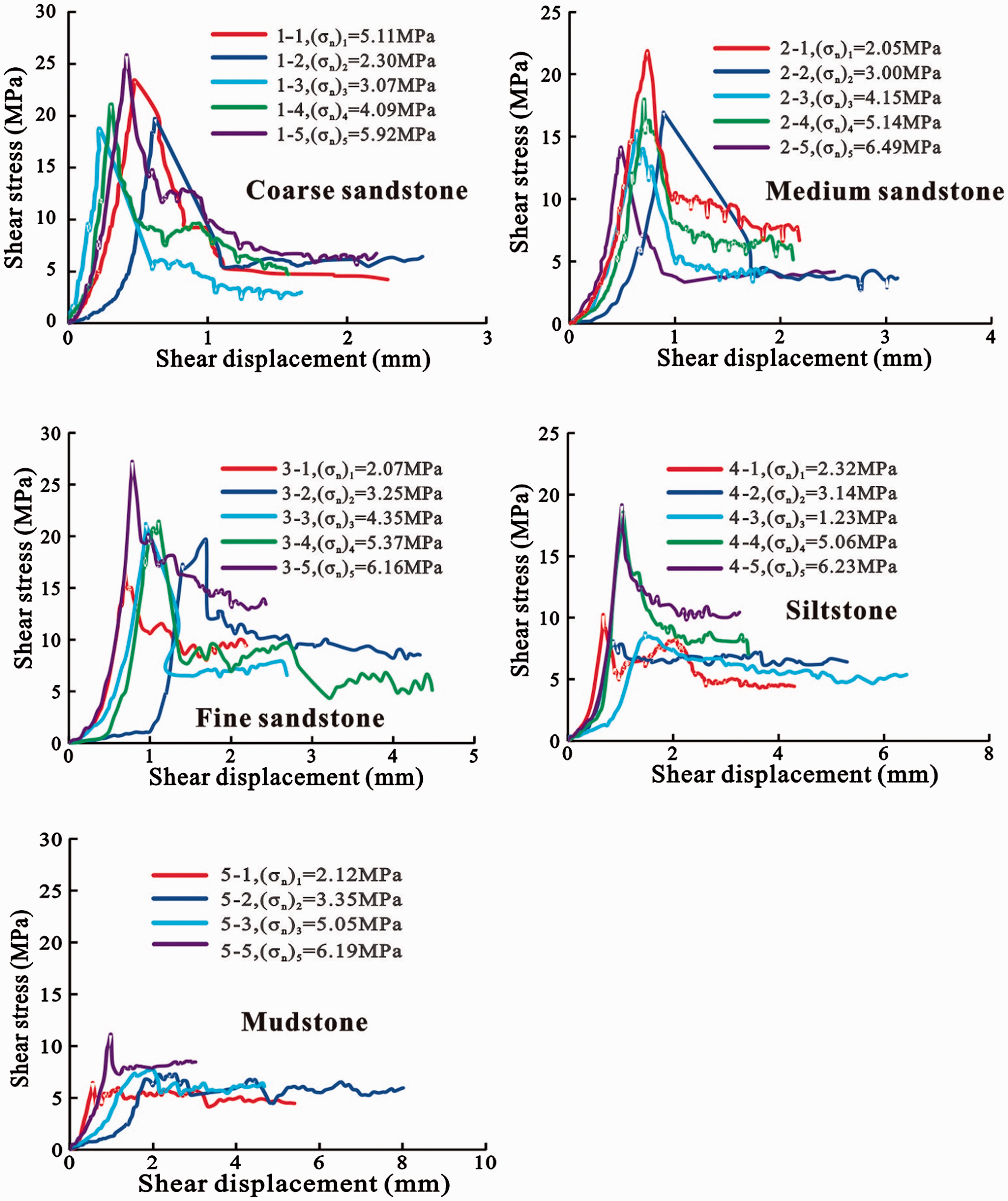
In addition, five different normal stress levels were considered to obtain the effect of normal stress on the shear behavior of the samples of various lithologies. The peak shear strengths of the five lithology groups increased with increasing normal stress. According to the data obtained from the five groups of direct shear test results, the relationship between normal stress and peak shear strength calculated by the Mohr–Coulomb criterion, equation (3), is plotted in Figure 5.
Shear strength curve of the specimens (Group 1, τ = 14.23 + 1.83σ, R2 = 0.88; Group 2, τ = 11.00 + 1.51σ, R2 = 0.80; Group 3, τ = 12.17 + 2.15σ, R2 = 0.85; Group 4, τ = 4.22 + 2.43σ, R2 = 0.82; Group 5, τ = 4.01 + 1.05σ, R2 = 0.58).
Influence of lithology on mechanical parameters
Figure 6 shows that the residual strength of the samples with different lithologies was substantially smaller than the peak strength. With the lithologic variation from coarse sandstone to mudstone (grain size from coarse to fine), the magnitude of the peak shear stress strength and yield shear strength decreases, which is most obvious from the sandstone to siltstone, as shown in Figure 6. However, Figure 6 shows that the shear strengths of the medium-grained sandstone are lower than those of the coarse-grained sandstone and fine-grained sandstone. We speculate that this lack of a decreased trend for the medium-grained sandstone may indicate a significant contribution of quartz to its composition. It has been suggested by Meng and Pan (2007) that for sandstone, the shear strength of the sandstone can partly be influenced by the mineral composition and cementation of mineral fragments. Perhaps a smaller amount of quartz and feldspar are included in the medium-grained sandstone with ferruginous cement, which has a weaker mechanical strength compared to the coarse-grained sandstone and fine-grained sandstone that is mainly composed of quartz and siliceous cement. In the samples of Group 2, the contributions of quartz and feldspar are likely to be small because of their possibly dominant compositions of sand-grade rock debris. Therefore, the medium-grained sandstone has a shear strength lower than those of the coarse-grained sandstone and fine-grained sandstone.
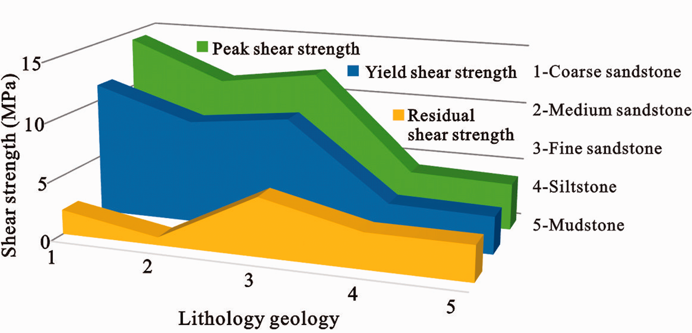
Variation of shear strength showing influence of lithology geology.
Coarse-grained lithologies exhibit a larger stress drop than fine-grained lithologies. Generally, the process of stress drop is essentially a process of gradual penetration of the fracture surface. However, as shown in Figure 5, there is no significant change in the friction angle of all the specimens, indicating that the crucial change of peak strength and yield strength is mainly caused by the change of cohesion. The change of stress drop magnitudes with lithology indicates that the cohesion changes from large to small when the grain size changes from coarse to fine. With the change in lithology, the greater the clay content is, the greater the strength reduction. The stress drop magnitude has a certain relationship with the cohesive force (Zhang et al., 2012). Compared with lithologies composed of fine grain sizes, lithologies with coarse grains have smaller residual shear strengths but larger peak shear strengths.
By comparing the relationship between shear displacement and peak shear stress under a given normal stress (Figure 7), it can be found that the peak shear stress generally shows a decreasing trend corresponding to the increasing shear displacement with the decrease of the clastic grain size of the rock composition. When the normal stresses are 2, 3, 5 and 6 MPa, the change in the shear stress versus lithology curves indicates that the peak shear strengths generally decrease and the shear displacement approximately increases with the decreasing grain size, except for medium-grained sandstone, possibly because of some reasons related to its composition and cement. Thus, the variation in the shear strength and displacement with lithology indicates that the grain size of different lithologies has an important effect on shear strength. The smaller the grain size is, the smaller the peak shear stress and the larger the shear displacement. Namely, rocks with small grains, such as mudstone or siltstone, tend to predominantly undergo shear failure with large shear displacements. This mechanical property is significantly affected by the clastic constituents of sandstone (Meng et al., 2000). As the grains become finer, the increase in clay minerals and mica as well as the slight decrease in feldspar will weaken the mechanical strength of sandstone. In addition, rock fragments are held together by cement. Cementation types also have important effects on shear properties. With a grain size gradation from coarser to finer, the cement changes from siliceous to calcareous or argillaceous, reducing the strength of rocks.
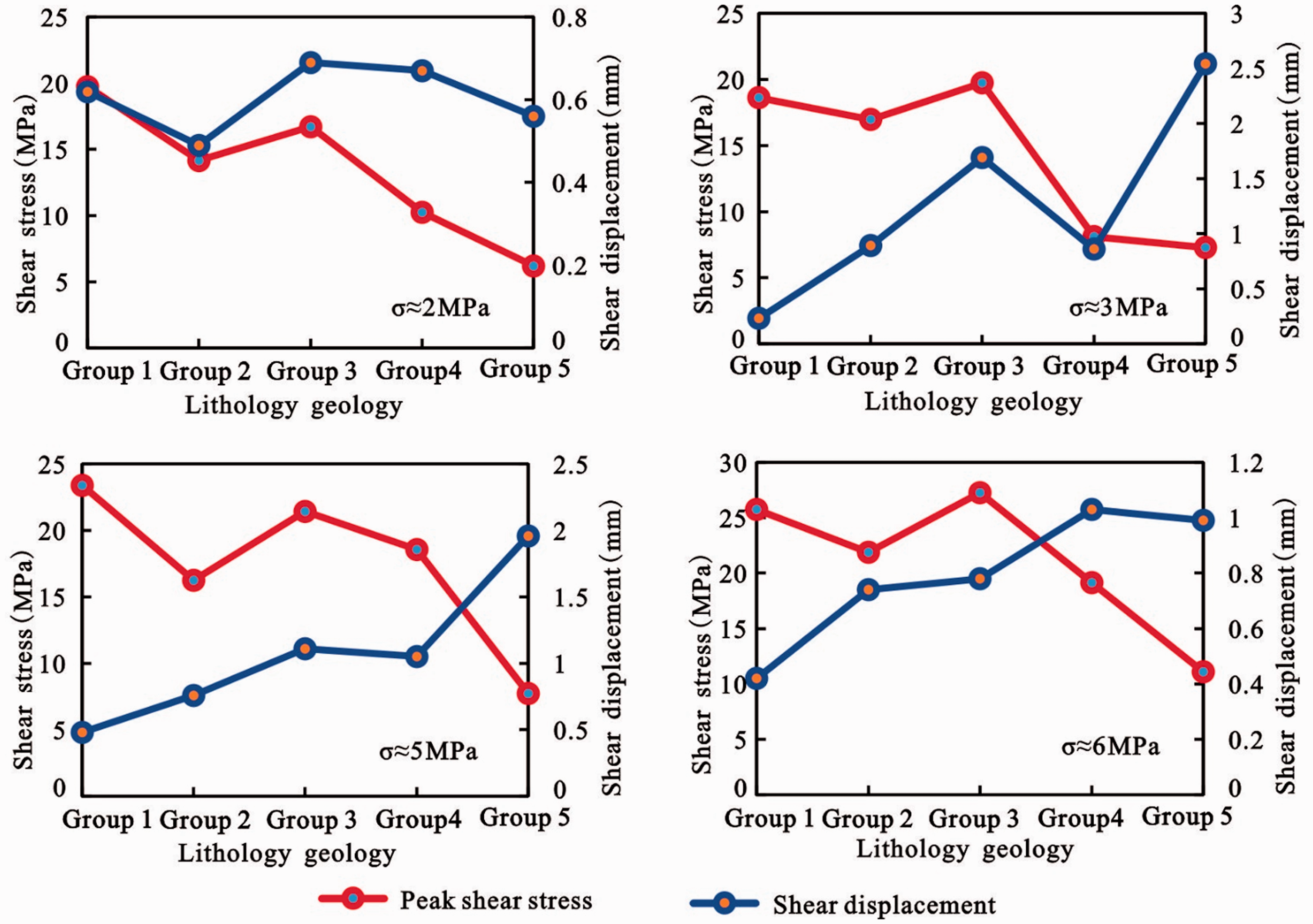
Variations of the peak shear stress and shear displacement versus lithology geology with normal stresses of 2, 3, 5 and 6 MPa.
To better understand the mechanical properties of different lithologies, approximately 330 tested mechanics parameters of coal-bearing rock samples were collected from the Huainan mining area in China. Figure 8 depicts the main mechanical parameters of these lithology samples. As the lithology changes from medium-grained sandstone to fine-grained sandstone, siltstone and mudstone, namely, a decrease in the grain diameter, the mechanical parameters considerably weaken, which reflects grain diameter softening (Meng et al., 2000). The mechanical parameters, such as the compressive strength, tensile strength, cohesion and elastic modulus, of the samples exhibit two obvious changes at the boundary between the medium-grained and fine-grained sandstones and the boundary between the fine-grained sandstone and mudstone, as shown in Figure 8. It is evident that medium-grained and fine-grained sandstones have the similar mechanical parameters (Figure 8), which is not expected due to the change in lithology. This may be related to the fact that the cement of medium-grained and fine-grained sandstones is mainly quartz with a grain-supported texture. The mechanical parameters of medium-grained sandstone are relatively discrete (Figure 8), which indicates that an increasing quartz content may provide a limited role to improve the mechanical strength of rocks in the study area.
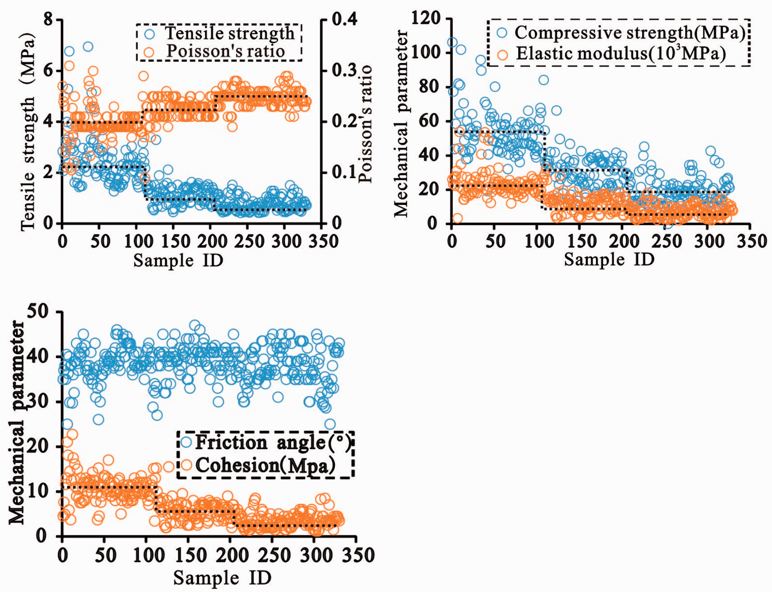
Variation of some mechanical parameters from collected 330 samples (ID 1–34, medium sandstone; ID 35–107, fine sandstone; ID 108–206, siltstone; ID 207–330, mudstone).
Classifying these samples as medium- to fine-grained sandstone, siltstone and mudstone, the average values of some mechanical parameters are summarized in Table 2. Taking medium- to fine-grained sandstone as the datum, the cohesions of the siltstone and mudstone decrease by 44% and 67%, the elastic moduli decrease by 47% and 70%, the compressive strengths decrease by 42% and 65%, the tensile strengths decrease by 51% and 69%, and the Poisson’s ratios increase by 9% and 12%, respectively. However, Poisson’s ratio increases incrementally, and the friction angle has no obvious change.
Average values of mechanical parameters obtained from collected 330 samples.
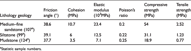
aStatistic sample numbers.
Lithology-controlled performances for shear failure of SMCBs
Based on the statistical data shown in Figure 8 and Table 2, the siltstone and mudstone composed of fine particles have generally lower shear strengths than the medium- to fine-grained sandstone (Figure 9(a)). There is no obvious change in the internal friction angle of different lithological samples, suggesting that the shear strength and shear displacement are mainly determined by cohesion. When the grain size of the rock mineral composition increases to the sand size, the rock has a high mechanical strength because of its mineral composition of single-crystal quartz (Figure 9(b)).
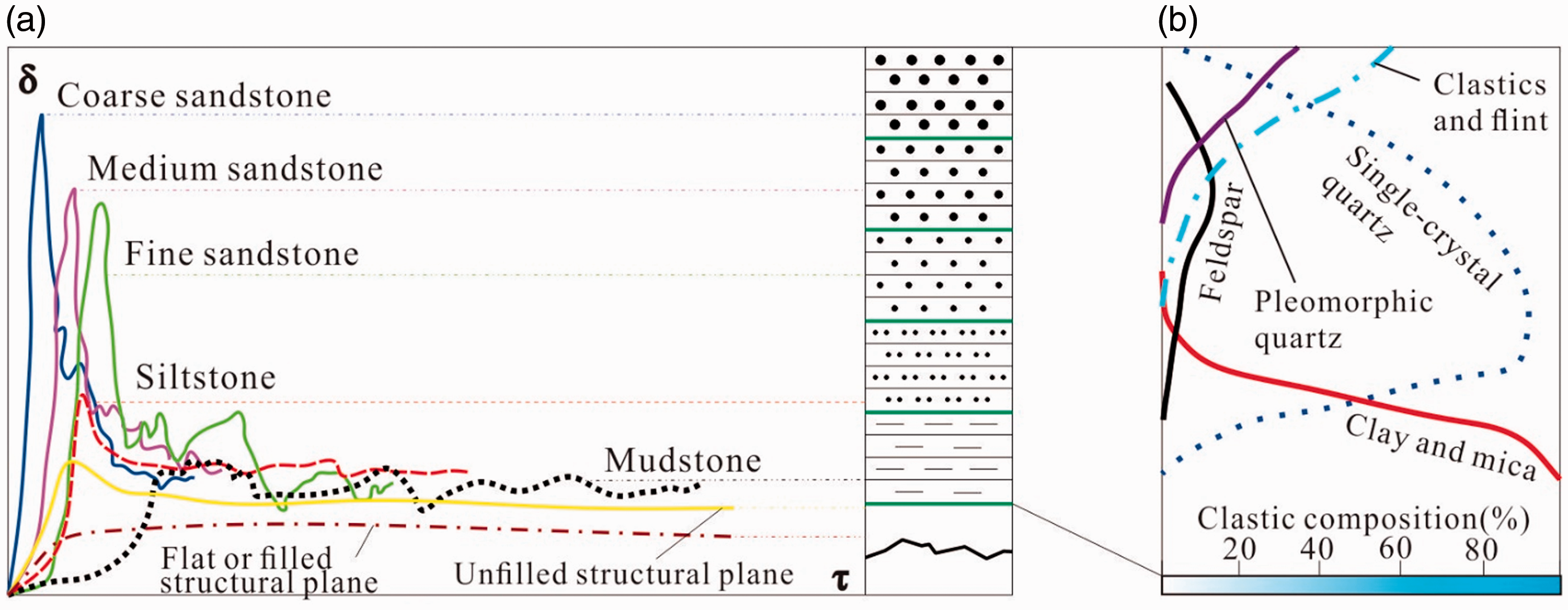
(a) Lithology performances for mechanical parameters caused by mineral compositions ((b) is modified from Meng et al., 2000).
In addition, some factors, such as cementation, have important effects on the mechanical properties of a rock under shear loading. The observed particle-supported sandstone sample generally shows high mechanical strength with siliceous and ferruginous cementation (Figure 10(a)). However, the siltstone and mudstone, mainly composed of clay and sliced mica, have low mechanical strengths due to their well-developed internal fractures and weak stiffness. Compared with sandstone, mudstone has a high clay content with poor argillaceous cementation (Figure 10(b)). X-ray diffraction analysis indicates that the clay minerals are approximately 59.0% of that rock type, and the proportion of kaolinite and the mixed-layer illite/smectite in clay minerals can reach 40% or more (Xu et al., 2015). As shown in Figure 10(c), a high content of flaky clay minerals in the mudstone samples can be observed by SEM. The flaky texture with weak interlayer mechanics provides the possibility of microscopic shear and slippage.
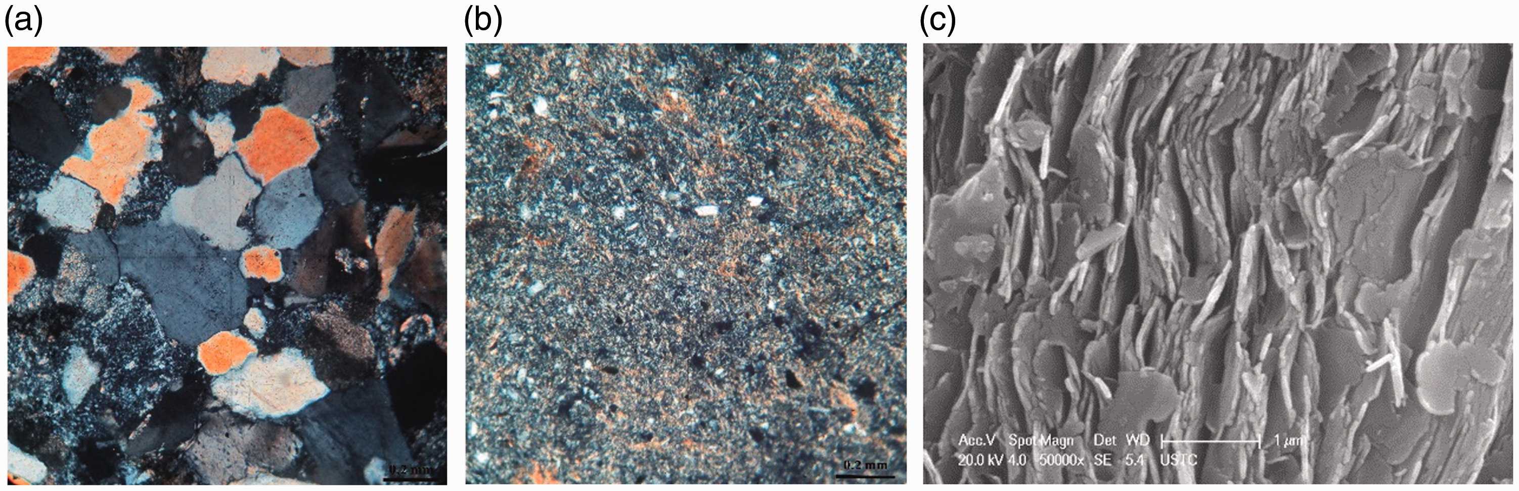
Thin-sections and SEM photomicrographs showing diagenetic minerals of sandstones and mudstones in coal-bearing strata in Huainan mining area. (a) Sandstone displays the wide array of medium-grained quartz with approximately 80% of the rock composition. The majority of framework grains showing porous cementation. Minor amounts of siderite cements quartz grains. Detrital silty mudstone grain is present in small quantities as a matrix within the grain-supported sand. Cross-polarized light. (b) Silt-bearing mudstone showing a majority grains are silt-grained and clay, about 10% and 90%, respectively. The detrital composition is mainly quartz with a small amount of feldspar. Minor amounts of the detrital grain size is 0.08 mm. Cross-polarized light. (c) SEM photomicrograph showing relatively textural, flaky clay minerals of mudstone.
Thus, the mineral composition and cementation of mudstone can significantly weaken its mechanical strength. In summary, with the decrease in the grain diameter of rocks (lithologies varying from sandstone to mudstone), decreasing quartz and increasing clay mineral contents are important factors for the decrease in shear strength and cohesion, which further leads to weakening of the shear strength of rock. Therefore, the shear mechanical parameters, which is controlled by varying Lithology-controlled performance, has a significant effect on the sequence and location of potential shear failure for SMCB in drilled strata.
Moreover, there may be many failures of the methane capture borehole around the panel induced by mining activities. The Lithology-controlled performance and possible optimal location of the shear failure are analyzed, but other factors, such as geological factors and the presence and geometries (dip angle) of structural planes, may affect the Lithology-controlled performance in terms of shear failure. The cohesion of structural planes is generally 0.005–1.0 (Brady, 2006), which is significantly different from that of rocks. Conventionally, the thick interlayer will decrease the shear strength of the structural plane, and the presence of more gouge implies a decreased shear strength. For the mudstone interlayer, the cohesion and friction coefficient of the structure surface will obviously decrease with increasing water content (Papaliangas et al., 1993).
The conclusions are reasonable and coincide with engineering practice. Figure 11 displays stratigraphic sections of the overlying strata in some damaged boreholes induced by shear failure, and these sections include mainly mudstone, siltstone and lithological boundaries. Compared with the failure of rock masses of different lithologies, the driving force required for generating slippage and instability along the structural surface is smaller, and the shear failure caused by the structural plane is preferential.
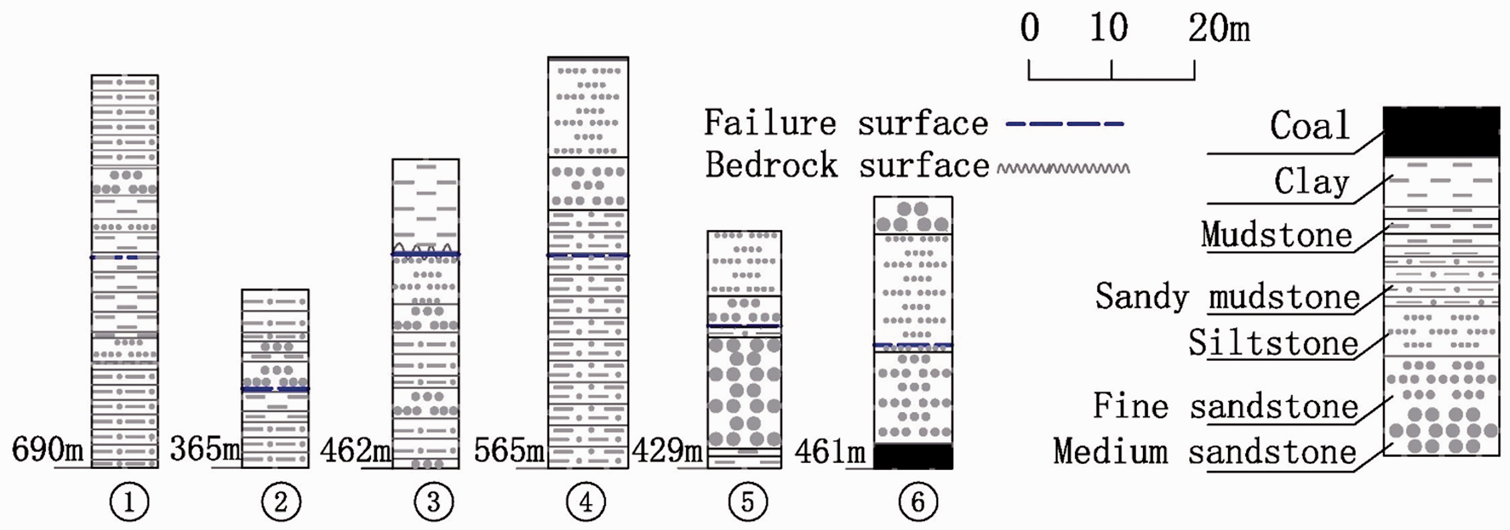
Stratigraphic sections of the strata in some damaged boreholes in the Huainan mining area (modified from Xu et al., 2014).
However, the shear failure of casing is affected by the overlying strata movement, mining engineering, geological conditions, etc. The tested mechanical properties are related to the physical properties of a rock mass, such as porosity, water content, and the processing and loading of the specimens. Furthermore, the structural plane and dip angle play important roles in Lithology-controlled performance in terms of shear failure. Casing failure is the result of the coupling of many geological and engineering factors. In this paper, the influence of lithology on shear failure is discussed. Due to the complex reasons for SMCB instability, the study of other geological and engineering factors is a further research direction.
Conclusions
In this paper, the shear response of samples of different lithologies was studied by a direct shear test under a CNL. The effects of the Lithology-controlled performance on the shear displacement and the possible location of shear failure are highlighted. Several main conclusions can be obtained:
The specimens of various lithologies show that the shear strength increases linearly with the initial normal stress. The shear stress of nearly all specimens shows a tendency to increase first and then decrease as the shear displacement increases, indicating obvious brittle failure characteristics. With the lithology varying from coarse-grained sandstone to mudstone (the grain size varies from coarse to fine), the shear stress exhibits an obvious trend of decrease with significant shear displacement. The jump in rock mechanics properties at the lithological boundaries is in response to the changes in grain size, which is mainly determined by the composition of the rock specimens. The cohesion may be the main reason for the step change in shear strength. The lithologies that have a low content of quartz and a high content of clay, such as siltstone and mudstone, and structural planes have poor shear strength and failure resistance, and they are the sections of the borehole to most likely fail. The detection results at the close of the borehole verify the prediction. Protective measures at these sections can improve borehole stability.
Footnotes
Acknowledgements
We thank Huainan Mining Group providing the test results.
Declaration of conflicting interests
The author(s) declared no potential conflicts of interest with respect to the research, authorship, and/or publication of this article.
Funding
The author(s) disclosed receipt of the following financial support for the research, authorship, and/or publication of this article: This work was supported by the National Natural Science Foundation of China (Grant No. 41727801), the Key Research and Development Program of Anhui Province (Grant No. 1804a0802203), Program of Study Abroad for Young Scholar sponsored by Education Department of Anhui Province (gxgwfx2019012) and Natural Science Foundation of Anhui Province (Grant No. 1708085ME133).