
Abstract
A novel loop heat pipe used for data center with a liquid line wick is designed, and its one-dimensional steady-state mathematical model is developed based on the energy and thermodynamic equilibrium of each component and the simulation results were validated by comparing with the experimental data in this work. The compensation chamber of the loop heat pipe was removed, and a section of capillary wick was added in the end of liquid line in order to reduce heat leakage and vapor backflow and increase working medium circulation power. The mathematical model of the novel loop heat pipe can be used to predict the operating temperature of each characteristic point with small relative errors of <13%. A parametric study of the steady-state performance characteristics including the effects of material, diameter, length, and porosity of liquid line wick are conducted, which provides a powerful basis for the design of novel loop heat pipe experiment.
Keywords
Introduction
With the rapid development of electronic and communication technology, data center has been built intensively. The energy consumption of data centers is approximately 1.1%–1.5% of the total global electricity consumption in 2011, and it will continue to increase with the rate that is doubling every 2 years until 2020 (ICTresearch, 2018). Among the above huge energy consumption, cooling device, as one of the main infrastructures providing recommended working environments for servers, accounts for about 30%–40% of total consumption. With the central processing unit manufacturing level increasing, computer chips are gradually developing towards the trend of high integration and miniaturization, which leads to the decrease of effective heat dissipation area and the sustained increase of heat flux. But traditional data center adopts room-level and cabinet-level cooling, which cannot effectively and timely cool down the electronic components, resulting in local hot spots problem. However, loop heat pipe (LHP), a two-phase cooling device, which is able to passively transport a lot of heat over long distances, can solve this problem well (Faghri, 1995). It also makes good use of natural cold sources so that data centers can be cooled with less energy consumption (Saucius et al., 2005). The LHP can also be used for heating, especially when integrated with the heat pump system. There are two kinds of conventional LHPs: cylinder type and plate type. The LHP with cylinder evaporator has been widely used in small spacecraft thermal management (Bugby et al., 2005; Orlov et al., 1997). The LHP with flat evaporator can better fit the structure of chips, so its application in the data center has gradually become popular. Generally speaking, the LHP is composed of evaporator, vapor/liquid line, condenser and compensation chamber (CC). Since the evaporator is directly in contact with heat source, its structure, material, size, and other parameters directly affect the operating performance of the LHP.
In order to improve the heat transfer and operating performance of LHP with flat evaporator, a lot of experiments have been done on testing the impact of various design parameters on the performance of LHP. Singh et al. (2008) conducted an experiment on an LHP with thickness of 10 mm and diameter of 30 mm. They found that the start-up time of LHP increases with the decrease of heat load and its minimum thermal resistance was able to achieve 0.17°C/W at a load of 70 W. Chuang et al. (2014) proposed a gravity-assisted LHP operating theory, which includes the condition when the condenser is higher than the evaporator. It means the LHP system is driven by pressure gain from both surface tension and gravity. The proposed hypothesis was validated by an experiment at 25.4, 76.2, and 127.0 mm positive elevations and used neutron radiography for a nondestructive visualization study. Finally, the model prediction is in good agreement with the experimental data. Maalej and Zaghdoudi (2007) carried out a study on Flat Mini Heat Pipe (FMHP) with a combined capillary structure including axial grooves and screen wicks and concluded that the heat transfer enhancement depends on the input heat flux rate, the screen mesh porosity, and the FMHP orientation.
The feasibility and accuracy of using Computational Fluid Dynamics (CFD) and a mathematical model to study the heat pipe have been confirmed by a large number of scholars (Ling et al., 2015, 2017; Yue et al., 2018a, 2018b; Zhang et al., 2017), and they also have used similar mathematical models to optimize LHPs. Chuang et al. (2002) and Chuang (2003) presented a one-dimensional (1-D) steady-state model with the capability of predicting two-phase pressure drop and heat transfer. It can adequately predict steady-state temperatures at both zero and adverse elevations. But the model cannot be used to predict several issues including temperature hysteresis, start-up, temperature oscillations, etc. which was observed by experiment. Vlassov and Riehl (2008) presented a mathematical model of an LHP that can calculate the dynamic vapor–liquid front in the condenser, as well as the rate of flooding in the CC, and the eventual entering of vapor phase in the liquid line and partial condensing of vapor in the vapor line. In situ experiments showed that the model could predict the LHP behavior within 5°C of accuracy (for a heat load range between 2 and 60 W). Kaya and Goldak (2006) developed a model that is based on the steady-state energy balance equations at each component of the LHP and studied the heat and mass transfer in the capillary porous structure. They found that the superheat limits in the capillary structure can be estimated by using the cluster nucleation theory. To increase the boiling heat transfer limit, it was desirable to maintain very good contact at the fin–wick interface along with the elimination of the non-condensable gases. More detailed descriptions of the mathematical model of LHPs can be found in Bai et al. (2009, 2010, 2011) and Ramasamy et al. (2018). For the LHP with flat evaporator, it can mainly be divided into two types according to the position of CC and evaporator: integrate type (CC is above evaporator capillary wick) and connection type (CC is at the end of evaporator, connecting liquid line and evaporator) (Siedel et al., 2013, 2015; Zhu and Yu, 2016).
In this paper, a novel LHP with a flat evaporator is designed. Compared with conventional LHPs, the novel LHP has no CC, and the end of the liquid line is filled with capillary wick, which can help to reduce heat leakage and prevent the vapor from entering into the liquid line. The working fluid in the inlet of liquid line wick always stays at a subcooled condition, which is beneficial for a successful start-up and steady operation of LHP. In order to analyze the mechanism of heat transfer and improve its performance, a 1-D steady-state mathematical model of the novel LHP was developed based on the energy and momentum balance equation of each part of the LHP. The influence of the LHP design parameters on its operating performance is also analyzed.
Mathematical model
The conventional LHP is divided into five parts: evaporator, vapor line, liquid line, condenser and CC. For the most conventional LHPs, the temperature difference between evaporator and CC leads to the heat leakage and vapor backflow from the evaporator to CC. The key difference between the novel LHP and conventional ones is that the CC of the novel LHP is removed, and a length of sintered wick is added in the end of liquid line to prevent vapor permeation and heat leakage. The new structure is shown in Figure 1. Its main structural parameters are shown in Table 1. Due to the structural changes, the heat and mass transfer processes in the novel LHP are quite different from those in traditional LHP. In this study, a steady-state mathematical model of the LHP is developed based on energy and thermodynamic equilibrium between each component. In order to simplify the model, the following assumptions are made:
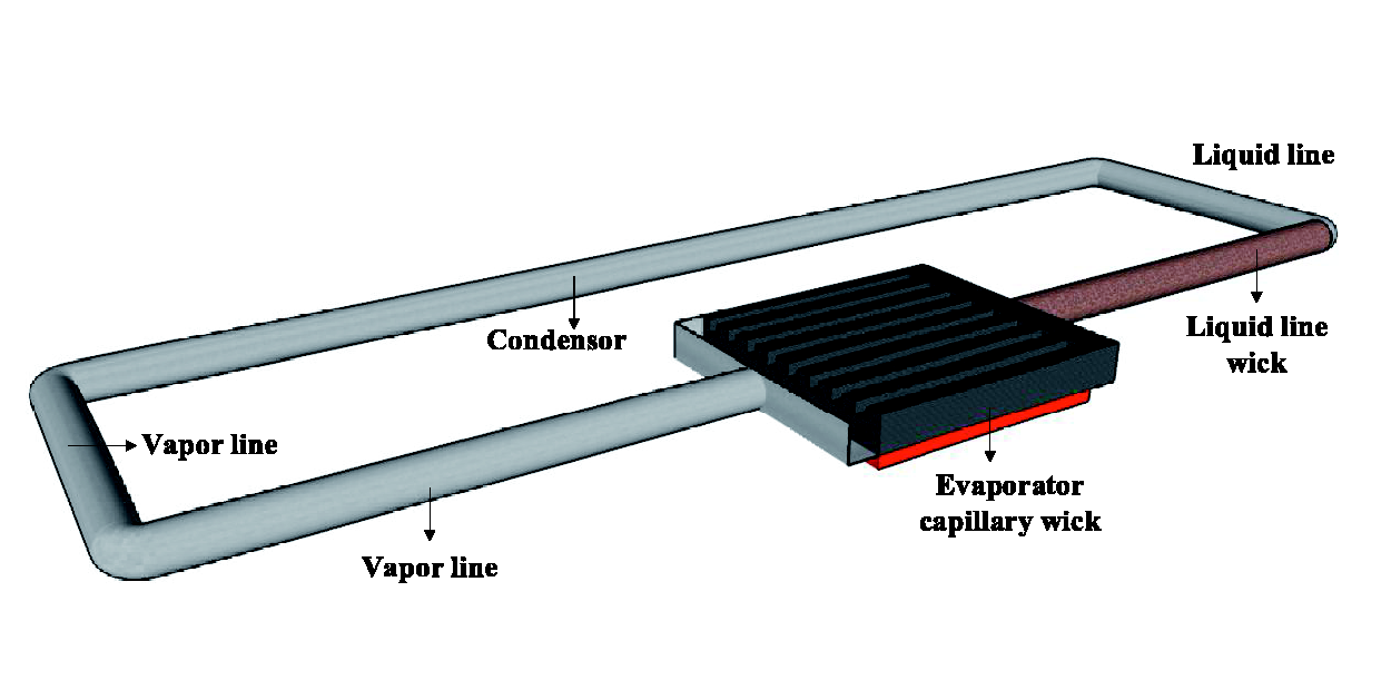
The novel LHP schematic diagram.
Main structural parameters of the LHP.
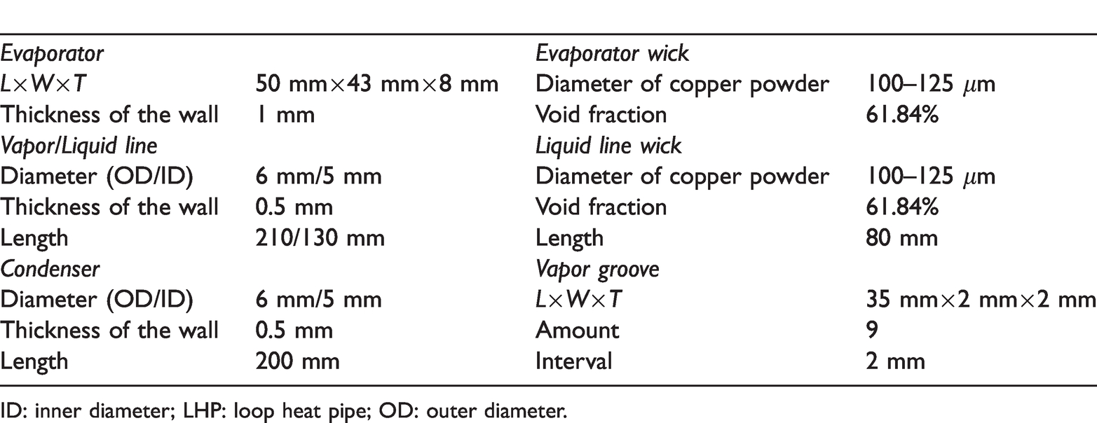
ID: inner diameter; LHP: loop heat pipe; OD: outer diameter.
The working medium flow inside the LHP, no matter laminar flow or turbulent flow, is considered as incompressible.
Part of the heat which is input into the evaporator and passes to the liquid line through the shell of the pipe and the wick is considered as heat leakage.
The vapor in the evaporator and condenser is not overheated, and the superheating process is ignored.
The phase transition process in the condenser is isobaric.
The heat transfer between LHP components and the ambient is considered in the model, and the ambient temperature was constant at 20°C.
Energy balance
Evaporator
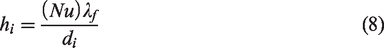
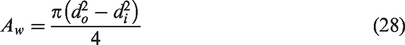
The heat input from the heat source to the evaporator Qin is mainly divided into three parts, including the evaporation latent heat of working fluid Qev, heat transferred from the evaporator to the liquid line wick Qev_llw, and heat dissipated to the ambient Qev_amb. The following equations applied

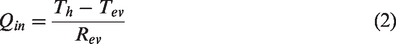


The convective heat transfer coefficient can be obtained from Heat Transfer Handbook. The heat load and condensation temperature had little influence on the thermal resistance Rev, so it is taken from the experimental results.
Vapor/liquid line
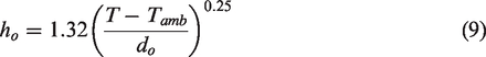
Vapor and liquid lines are long round pipes. Ignoring the temperature change of working medium and the axial heat transfer, the vapor/liquid line mainly has heat loss to the environment Qvl_amb/Qll_amb, which can be calculated as below


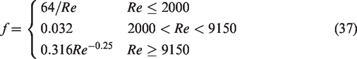
Due to the large ratio of pipeline length to diameter, the flow of working fluid is considered as fully developed flow. For fully developed laminar flow, Nu = 4.36, and for fully developed turbulence flow, Nu = 0.023Re0.8Prn, where n is 0.4 when tube wall temperature is higher than liquid temperature, and n is 0.3 when tube liquid temperature is higher than wall temperature.
The heat transfer mode between the pipe and the environment is natural convection. Its convective heat transfer coefficient can be expressed by
Condenser
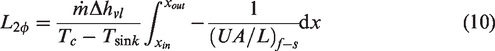
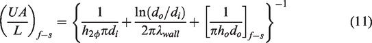
Because the specific heat capacity of vapor is small, the cooling process of internal superheated vapor is ignored. Then, the condensation process is divided into two-phase condensing section and supercooling section. Suppose that the flow in the condenser is annular.
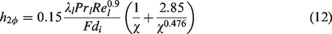
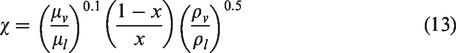
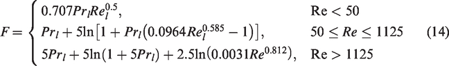
The length of two-phase flow condensing sections can be obtained from (Traviss and Rohsinow, 1973)
Energy balance in subcooled section can be expressed as
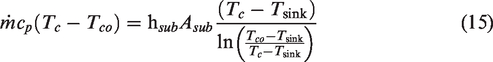
The temperature of the working medium at the condenser outlet is solved as

Liquid line
When the working medium flows through the liquid line, heat transfer occurs between the ambient and the liquid line wick, and the energy balance can be expressed by

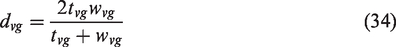
Liquid line wick
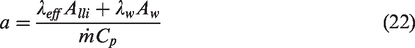
When the heat transfer process in the LHP reaches a stable state, the energy balance in the liquid line wick can be expressed by equation (19) (see Figure 2)

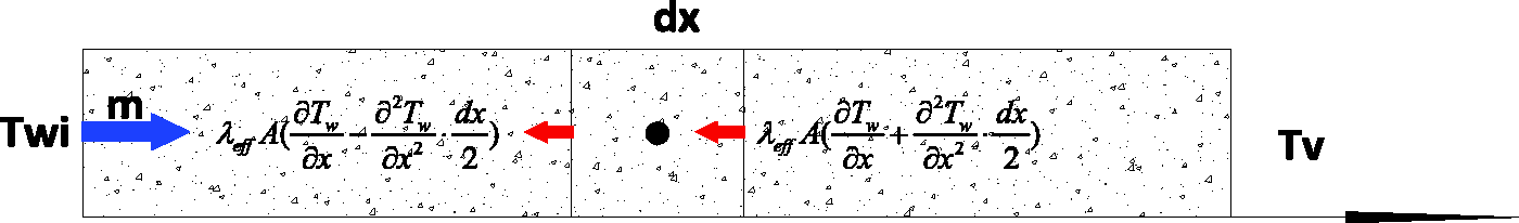
Energy balance of liquid line capillary wick.
According to the working liquid flow and capillary heat balance in the liquid line wick, while ignoring the heat transfer from the surface of liquid line wick to the ambient, the following equation can be obtained
The above equation can be simplified and solved as

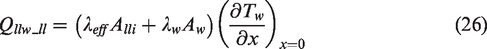
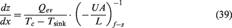
Then heat leakage from the evaporator to the liquid line wick can be represented by the following equation

The heat leakage from liquid line wick to liquid line can be expressed as

Pressure balance
The capillary force provided by the wick must be larger than the total pressure drop of the LHP to ensure sufficient circulation power of the working medium, that is

Evaporator capillary wick
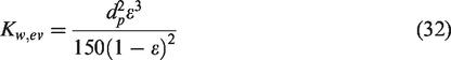
According to Darcy’s law, the pressure drop of the working medium through capillary wick is
Vapor groove
Since vapor is continuously generated along the vapor groove, its mass velocity increases almost linearly along the vapor groove, and its velocity reaches the maximum at the outlet (Bai et al., 2009). Maximum velocity in vapor groove can be presented by
To determine the Reynolds number, the hydraulic diameter of vapor groove is used as
The effective length of vapor groove is about half of its actual length, which can be obtained by the following equation

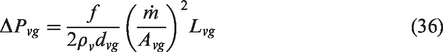
Then the pressure drop in the steam channel can be expressed by the following equation
Vapor/liquid line
The pressure drop of vapor and liquid line is calculated in the same way as the pressure drop of vapor groove, but the calculated length is equal to the actual length of vapor and liquid line.
Condenser
Because the LHP is placed horizontally, the gravitational pressure drop inside the condenser can be ignored. The superheated section of vapor in the condenser is neglected, and the working medium in the condenser is a two-phase flow. In the two-phase region, the working medium condenses from the gaseous state to the liquid state. This process can be treated as a circular flow in a horizontal tube.
The pressure drop gradient in the two-phase flow process is then performed by the following equation
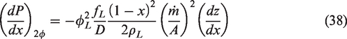
According to Lockhart and Martinelli (1949), the two-phase multiplier of two-phase flow in a horizontal tube is deduced as follows
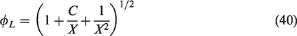
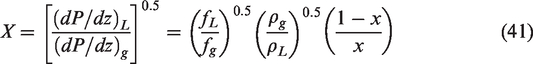
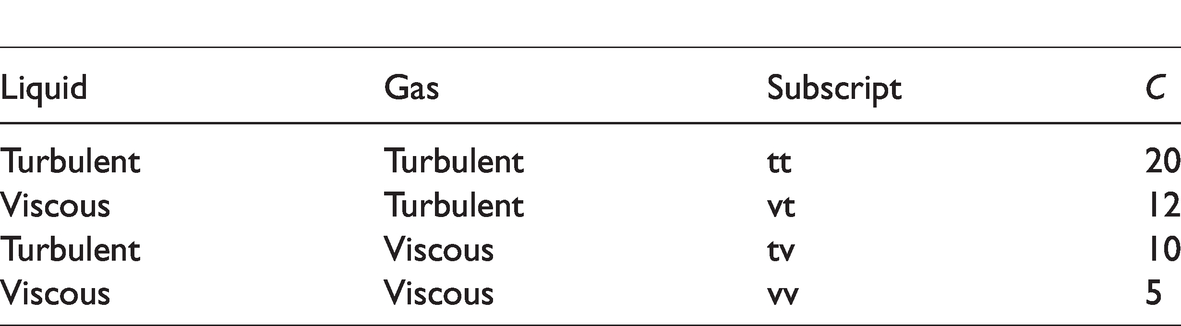
The value of constant C is determined by the flow state of vapor and liquid in the pipes and is presented in Table 2.
The value of C in Lockhart and Martinelli correlation.
Liquid line capillary wick
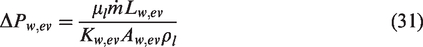
When the working medium flows through the liquid line wick, pressure drop will also occur. The calculation method is similar to that in the wick of the evaporator
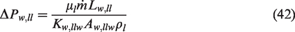
Thermodynamic equation
The working medium is in a saturation state in the two-phase flow section of the evaporator and the condenser. According to the thermodynamic equation, Tv and Tc have the following relations
Solution algorithm
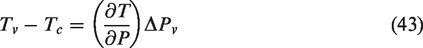
The solution flowchart for the LHP models presented above is shown in Figure 3. The main calculation steps are as follows:
Solution flowchart.
Input heat load, ambient temperature, condensate water temperature, and evaporator thermal resistance.
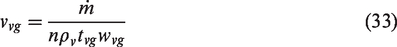
Assign initial evaporation temperature Tv, calculate the working medium flow rate in the LHP, where
Calculate the length of two-phase flow and pressure drop in the condenser, and then calculate the outlet temperature of the condenser.
According to the energy balance of liquid line, calculate the inlet temperature of liquid line wick.
Calculate heat leakage from the evaporator to the liquid line wick Qev_llw and heat transfer from the wick to the liquid line Qllw_ll, respectively. Calculate the new round of working medium flow with
Calculate the energy balance relationship between liquid line wick and evaporator, and adjust the evaporation temperature if it is not convergent. If convergence condition is reached, output calculation results, including Tv, Th, Tco, Twi, Qev_llw, and Qllw_ll.
Results and analysis
Model validation
In order to verify the accuracy of the mathematical model, the steady-state temperature data in the novel LHP experiment was compared with the simulation results, and the average temperature of the LHP with 10 min interval under steady-state operation was taken. The location of the measuring points in the experiment is shown in Figure 4, where T1 measured the heating surface temperature Th, T3 measured the vapor temperature Tv, T6 measured the condenser outlet temperature Tco, and T7 measured the liquid line capillary wick inlet temperature Twi. As for the input parameters of the model, their values are in consistent with those in the experimental process. The uncertainty of experimental data is mainly caused by the change of experimental conditions and measurement accuracy of instruments. According to the experimental condition, the maximum uncertainty of the system thermal resistance is 1.46%.
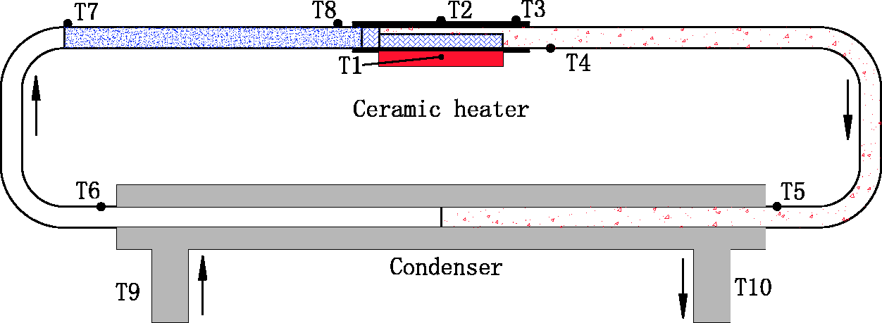
Schematic diagram of thermocouple position in experiment.
Figure 5 shows the comparison between the experimental data and simulation results when Tsink is 20°C and 30°C. Obviously, the simulation results of the novel LHP 1-D steady-state model are in good agreement with the experimental data and their relative error is below 13%, indicating that the model can predict the temperature of the heating surface, evaporator, condenser outlet, and liquid line capillary wick inlet very well when the LHP runs steadily.
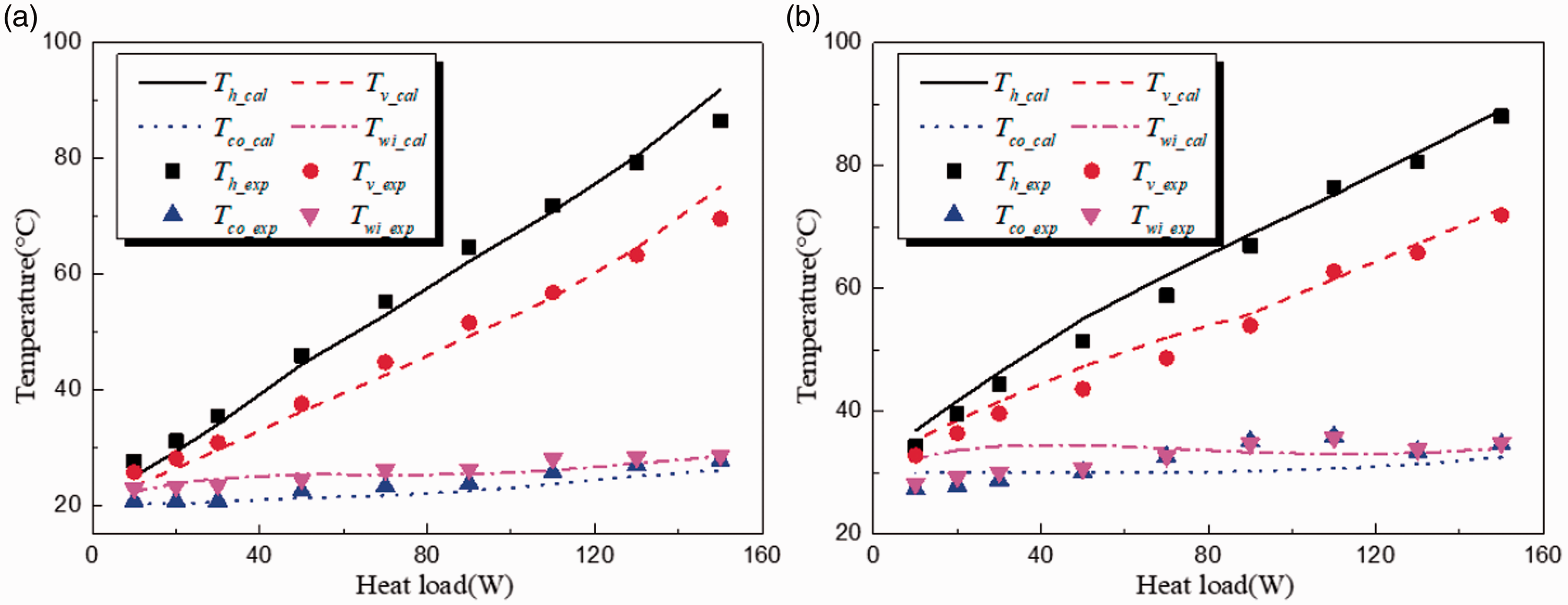
The temperature comparison between experiment and model for (a) Tsink=20°C and (b) Tsink=30°C.
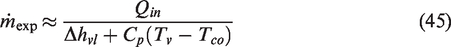
Experimental data are also used to verify the accuracy of liquid line wick heat transfer model. In the experiment, the flow rate of the working medium can be approximately represented by the following equation
Then the heat leakage from evaporator to liquid line wick can be described as

Similarly, the heat leakage from liquid line wick to liquid line is approximated as

Figure 6 shows the comparison of the model and experimental data for heat leakage from evaporator to liquid line wick and heat leakage from liquid line wick to liquid line. It can be found that the two kinds of heat leakage obtained by the model calculation are almost identical with the experimental data, indicating that liquid line wick model can accurately predict the temperature distribution, so it is reliable to use the 1-D steady-state model to analyze the operating performance of the LHP.
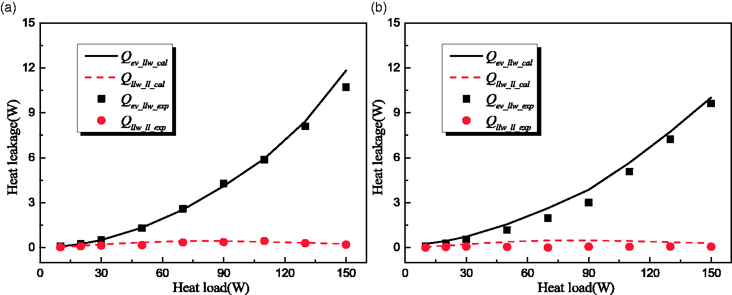
Comparison of heat leakage between model and experiment for (a) Tsink=20°C and (b) Tsink=30°C.
Effect of liquid line wick length on the performance of LHP
Figure 7 shows the variation trend of vapor temperature and the inlet temperature of the liquid line wick with the increase of heat load with length of the wick ranging from 0.05 to 0.10 m. The vapor temperature always increases with the increase of the heat load. When the heat load is <90 W, there are small differences among the vapor temperature with different liquid line wick lengths, which indicates that the vapor temperature is mainly determined by the heat load in this range. When the heat load is >90 W, the vapor temperature increases rapidly with the increase of the capillary wick length of the liquid line, especially when the capillary wick length of the liquid line is 0.10 m, the vapor temperature is much higher than those under other operating conditions. The reason is that in the case of low heat load, the temperature gradient between the evaporator and the wick changes little and there is little difference in heat leakage from evaporator to wick, as shown in Figure 8(a). Therefore, the flux of working medium is almost the same, and the subcooling of working medium from condenser varies little, so that the evaporator gets the same cooling capacity, and Tv is similar.
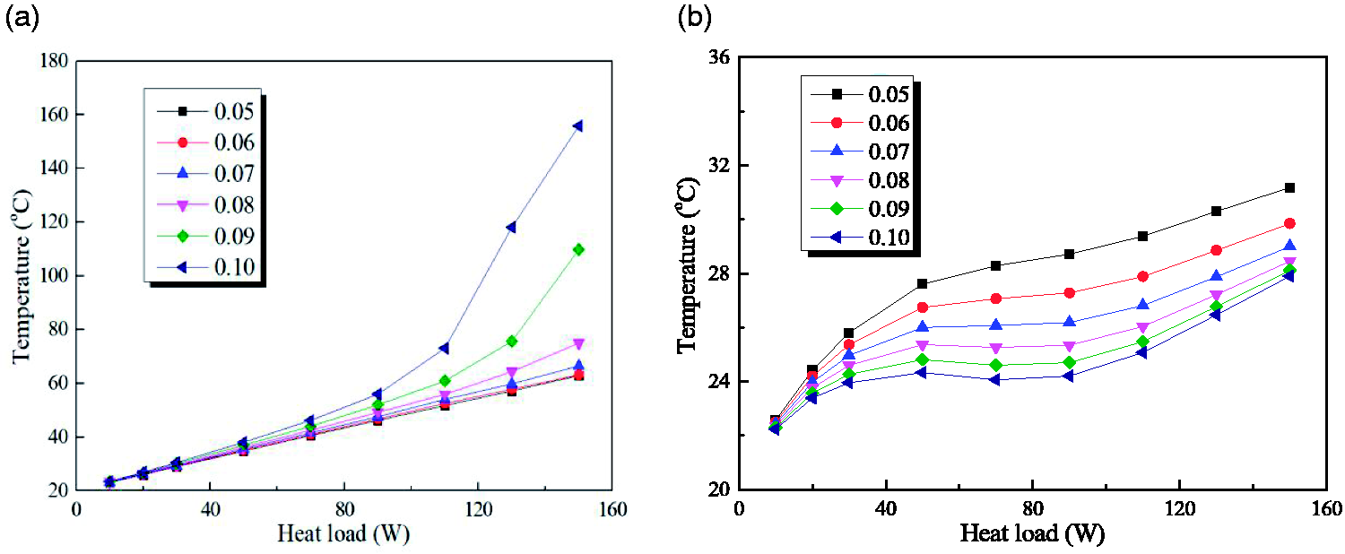
Effect of liquid line wick length on the (a) evaporator and (b) wick inlet temperature.
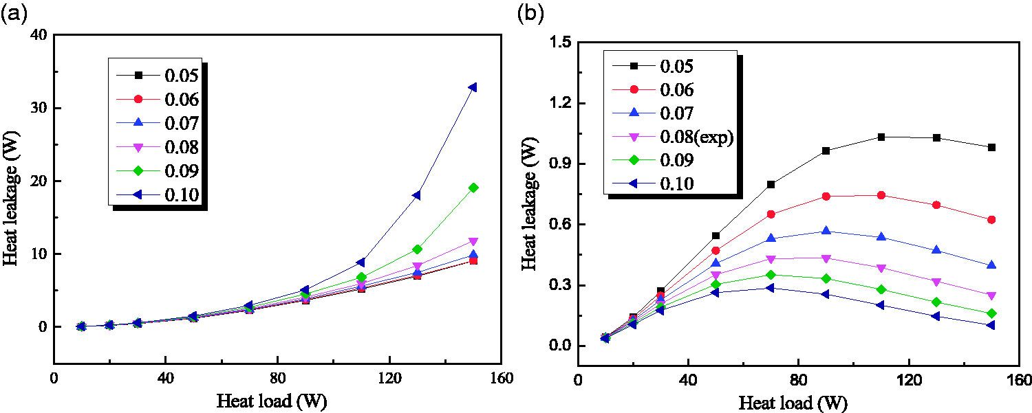
Effect of liquid line wick length on the heat leakage from (a) evaporator to liquid line wick and (b) liquid line wick to liquid line.
Under high heat load, the rising speed of Twi is far less than that of Tv, and the heat leakage from evaporator to the liquid line wick rises rapidly due to the increase of the temperature gradient. The heat input cannot be fully used for the evaporation of the working medium, which results in the decrease of the working medium flow under high load and cannot provide enough working medium for the evaporator. As a result, the temperature of the evaporator rises rapidly. When the heat load is constant above 90W, Tv increases rapidly with the increase of liquid line wick length. This is because the thermal resistance increases with the increase of wick length, so the heat leakage decreases and the heat inside the evaporator increases obviously. In addition, it is worth noting that if the length of wick is <0.07 m and continues to decrease, the steam temperature will change very little. The reason is that when the length of wick increases from 0.05 to 0.07 m, its thermal resistance changes from 3.51°C/W to 3.81°C/W. While when the length of wick increases from 0.08 to 0.10 m, its thermal resistance changes from 3.94°C/W to 5.12°C/W. It can be seen that when the length of wick varies from 0.08 to 0.1 m, the influence is greater. At this time, as shown in Figure 8(b), the heat leakage from liquid line wick to liquid line also changes very little and is <1.2 W. Twi increases as the heat load increases and when the heat load is constant, the increase of liquid line wick will reduce Twi. The reason has been mentioned in the previous analysis. The increase of heat load increases the working medium temperature at the condenser outlet, so the inlet temperature of the liquid line wick increases. It can also be found that, with the increase of heat load, Twi rises rapidly between 0 and 50 W, then becomes flat between 50 and 90 W, and rises slowly above 90 W. This is because Twi is affected by both heat leakage and condenser outlet temperature: when the heat load is low, the temperature of working medium at the condenser outlet changes little and the mass flow rate is small. The heat leakage increases rapidly with the increase of heat load, making Twi increase rapidly. In the case of medium heat load, due to the increase of mass flow rate of the working medium, the increase rate of heat leakage slows down and tends to become flat. When the heat load is >90 W, although the heat leakage starts to decline gradually, the working medium’s temperature continues to rise at the condenser outlet, and Twi continues to rise.
Effect of liquid line wick material on the performance of LHP
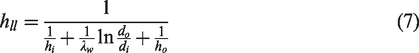
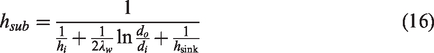
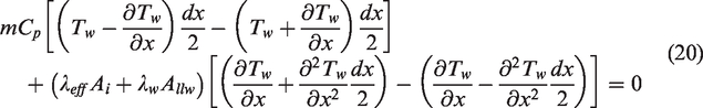
Because of the difference of thermal conductivity, the material of liquid line capillary wick also plays an important role in the operating performance of the LHP. Figure 9(a) shows the evaporator temperature when the wick materials are copper, aluminum, iron, lead, and organic materials, respectively. Obviously, Tv and Twi increase with the increase of thermal conductivity. However, compared with the length of wick, the effect of material on Tv and Twi is much smaller. When the heat load is 150 W, Tv is 74°C for copper and 66°C for organic material, the temperature difference is only 8°C. However, their thermal conductivities differ by almost 220 times. This is due to the fact that the wick heat leakage from the evaporator to the liquid line is less affected by the material, as shown in Figure 9(b). Although the thermal conductivities of different materials wick differ greatly, considering the wall material and area, the total heat transfer coefficient of capillary wick can be obtained by the following equation

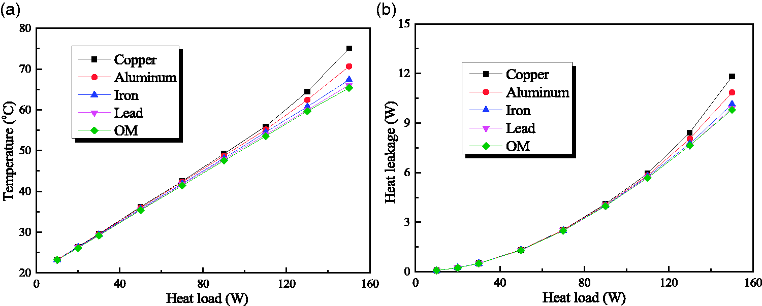
Effect of liquid line wick materials on the (a) evaporator temperature and (b) heat leakage from evaporator to liquid line wick.
The total heat transfer coefficients of capillary wick when its material is copper, aluminum, iron, lead, or organic are 0.0059, 0.0049, 0.0040, 0.0037, and 0.0035 W·m/K, respectively. The difference of total heat transfer coefficients of iron, lead, and organic is small, so the simulation curves of the temperature and heat leakage are relatively close especially under the working heat load of 120 W, indicating that heat leakage through the wall of the liquid line was the main influencing factor.
Effect of pipe diameter on performance of LHP
Figure 10 shows the characteristic temperatures and heat leakage at different pipe diameters. It can be found that when the heat load is <110 W, the pipe diameter has little influence on the vapor temperature, and their values are almost the same. When the heat load is >110 W, the change of pipe diameter between 2 and 4 mm has little influence on the vapor temperature. This is because when the pipe diameter increases from 2 to 4 mm, thermal resistance of the liquid line wall and wick changes from 3.97°C/W to 3.94°C/W, whereas when the pipe diameter increases from 5 to 6 mm, its thermal resistance changes from 3.75°C/W to 3.31°C/W. In the range of 4–6 mm, the influence is greater. When the pipe diameter is >4 mm, the vapor temperature increases with the increase of diameter. This is because when the heat load is small, it plays a leading role in the influence of heat leakage, so Tv will not change significantly with the increase of pipe diameter. When the heat load is large, it can be observed from equations (26), (27), and (28) that the increase of pipe diameter leads to the increase of capillary wick cross-sectional area, which leads to the increase of Qev_llw, Qllw_ll, and Twi, as shown in Figure 10(b) and (c). The mass flow rate of the LHP decreases, and the working medium temperature from the liquid line to the evaporator is higher. The circulating working medium cannot provide enough cooling capacity for the evaporator, so the evaporator temperature rises and the performance of the LHP becomes worse.
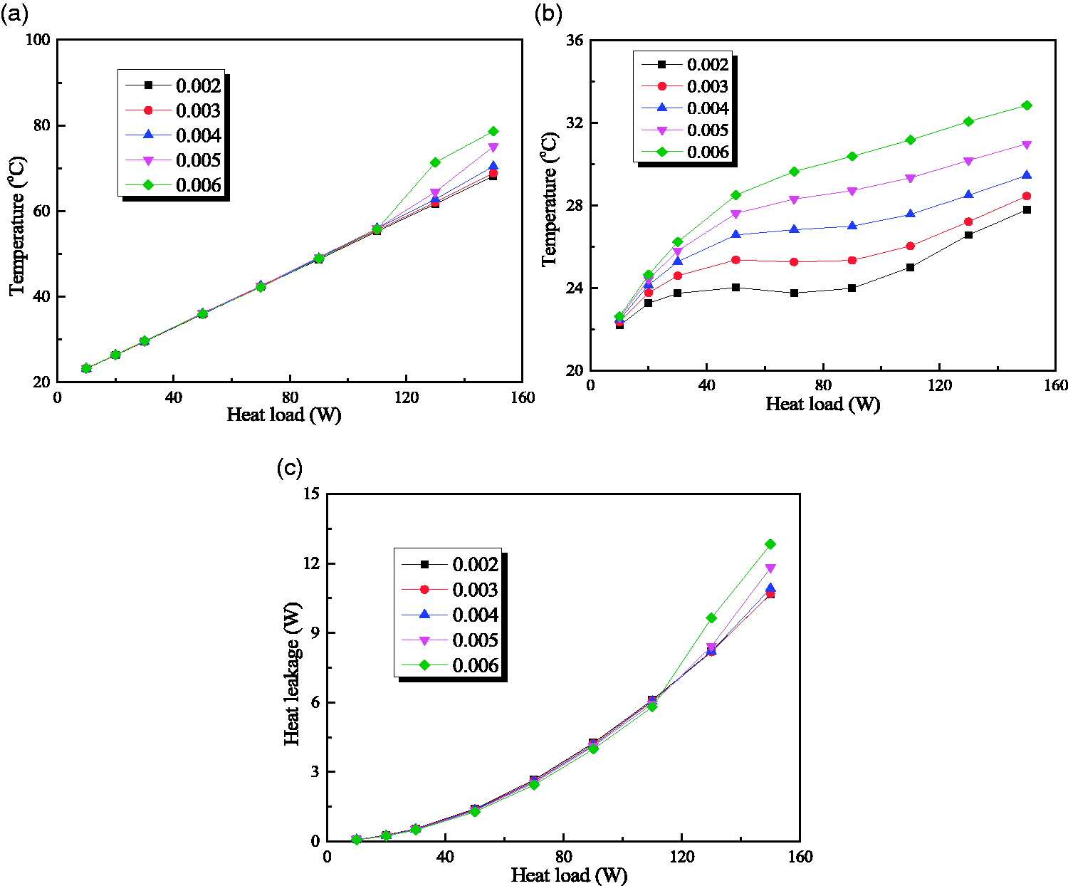
Effect of pipe diameter on the (a) evaporator temperature, (b) wick inlet temperature, and (c) heat leakage from evaporator to liquid line wick.
Effect of wick porosity on the performance of LHP
Liquid line capillary wick is a kind of porous structure sintered by copper powder. Its porosity is defined as the ratio of the total volume of wick to the pore volume. The smaller the porosity of the wick is, the larger the volume ratio of copper contained in the wick will be. Moreover, the thermal conductivity of copper is much larger than that of air, which means that the lower the porosity is, the larger the comprehensive thermal conductivity of wick will be, which leads to more serious heat leakage phenomenon, as shown in Figure11(c). The trends of vapor and wick inlet temperature are shown in Figure 11(a) and (b) and have been explained previously. When the porosity of wick decreases from 0.8 to 0.6, thermal resistance of wick changes from 4.60°C/W to 4.47°C/W, which leads to the little temperature variation of evaporator and wick inlet. Whereas, when the porosity of wick decreases from 0.5 to 0.3, thermal resistance of wick changes from 4.32°C/W to 3.66°C/W.
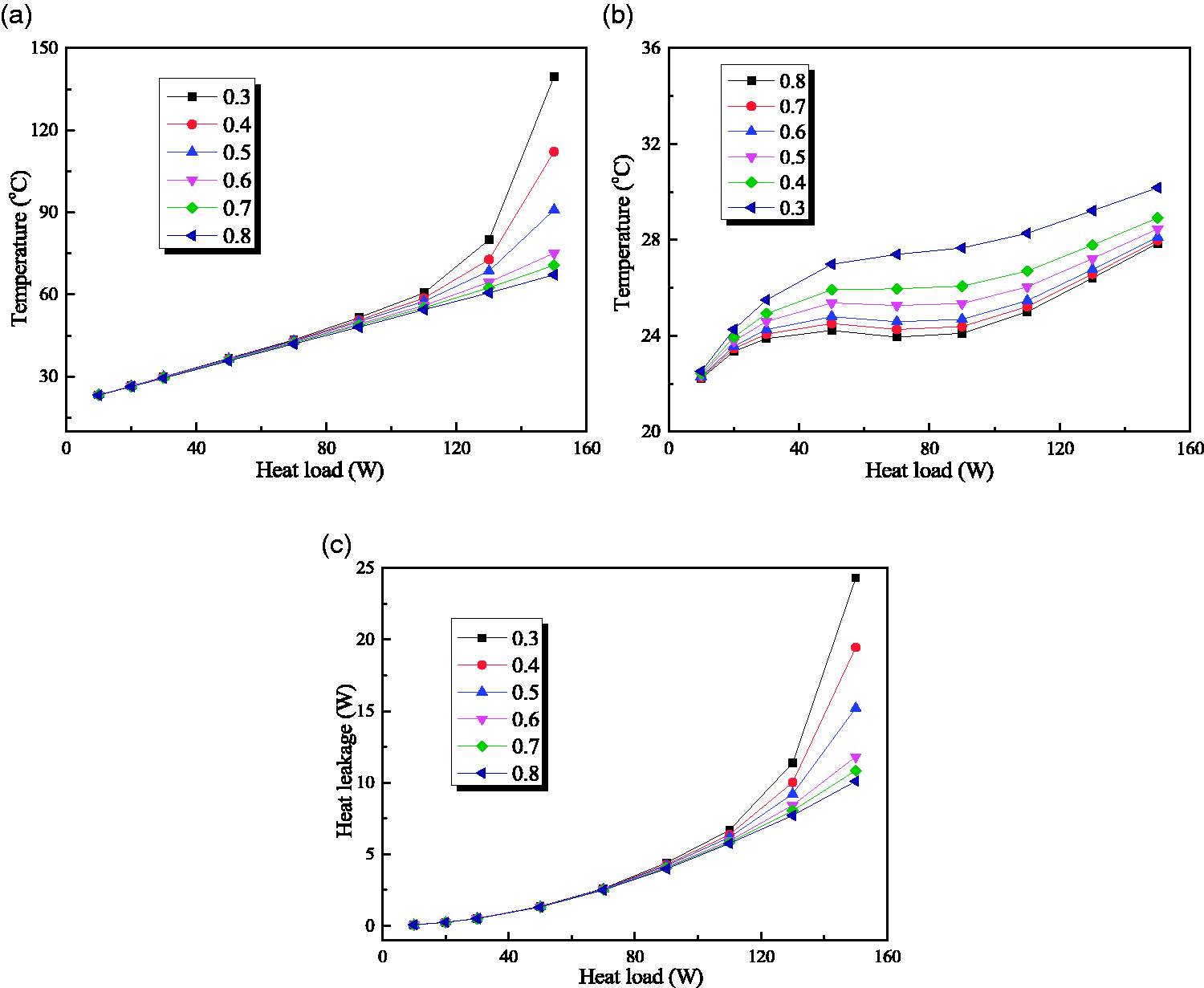
Effect of wick porosity on the (a) evaporator temperature, (b) wick inlet temperature, and (c) heat leakage from evaporator to liquid line wick.
Conclusions
A novel LHP with a liquid line wick is designed and its 1-D steady-state mathematical model is developed and validated by comparing the simulation results with experimental data in this work. The major conclusions can be summarized as follows:
The mathematical model of the novel LHP can be used to predict the operating temperature of each characteristic point with small error when the heat load is between 10 and 150 W. Therefore, a parametric study of the steady-state performance characteristics including the effects of material, diameter, length, and porosity of liquid line wick is conducted which provides a powerful basis for the design of novel LHP experiment. When the heat load is <90 W, changing the parameters of liquid line wick will not cause a big fluctuation of Tv and Qev_llw. When the thermal load is >90 W, the increase of liquid line wick, the decrease of material thermal conductivity, the decrease of cross-section, and the increase of porosity will help to reduce heat leakage, which is beneficial to the operation of the LHP. When the heat load is <120 W, the heat leakage accounts for only about 8% of the heat load, indicating that the novel LHP can notably reduce the heat leakage from the evaporator to the liquid line and operate at small heat loads.
Footnotes
Acknowledgements
The authors would like to thank the editors and anonymous reviews for their constructive suggestions and comments.
Declaration of conflicting interests
The author(s) declared no potential conflicts of interest with respect to the research, authorship, and/or publication of this article.
Funding
The author(s) disclosed receipt of the following financial support for the research, authorship, and/or publication of this article: This work was supported by International Science and Technology Cooperation Project of China (2017YFE0105800) and National Natural Science Foundation of China (NSFC) (Grant No. 51878254).