
Abstract
Environmental pollution in China is getting worse. The effective use of geothermal energy can solve the problem of greenhouse gas emissions. This paper introduces a new type of medium-deep geothermal energy utilization system named U-shaped docking well geothermal heat extraction system and analyzes its characteristics. The results show that the system can meet the needs of daily heating, and the heat transfer effect of this system is greater than the concentric casing heat exchange systems. This study provides a new idea for the use of medium-deep geothermal energy.
Keywords
Introduction
In recent years, many cities in China have experienced large-scale and long-lasting hazy weather, which has aroused strong public concern about air pollution. China is one of the countries with large reserves of geothermal resources in the world (Zhao and Wan, 2014). Geothermal resources refer to geothermal energy, geothermal fluids and their useful components underground, which can be used economically. Geothermal heating will provide support for the country to adjust its consumption of fossil fuels and reduce pollution (Kim et al., 2018; Russo et al., 2014; Wang et al., 2013; Yan and Qin, 2017). At present, more than 100 countries in the world develop and utilize geothermal energy and grow at a rate of 12% per year. According to the burial depth, it can be divided into the following three types: (1) shallow geothermal resources with burial depth less than 200 m and temperature less than 25°C; (2) medium-deep geothermal resources, buried depth 200–3000 m, temperature above 25°C; (3) dry–hot rock geothermal resources, the thermal storage rock mass is more than 3000 m deep, the temperature is greater than 200°C, no fluid or only a small amount of underground fluid. In contrast to shallow geothermal energy, deep geothermal energy can be used directly—with much higher energy output and without the need to install a heat pump to raise the temperature (Agemar et al., 2014). As deep geological exploration and drilling technologies have developed, the use of deep geothermal energy is becoming increasingly important (Zhao and Ma, 2015).
Research on U-tube geothermal systems has focused on the use of shallow geothermal energy, and their horizontal sections were not long (Chen et al., 2015; Li et al., 2013; Lyu et al., 2018). Sun et al. (2018) proposed a U-shaped closed loop geothermal system, but they didn’t consider the impact of the length of the horizontal section. For the middle-deep geothermal resources or dry hot rock geothermal resources, most of the previous studies have focused on two aspects: (1) using concentric casing heat extraction system (Bae et al., 2018; Cho et al., 2016; Jin et al., 2012), but both the flow rate and the heat exchange efficiency were low; (2) drilling multiple deep wells for production and injection of working fluid, using fracturing, acidification and other measures to connect the heat reservoir (Cui et al., 2018; Yanagisawa et al., 2008; Zeng et al., 2013). But the process is complicated, the formation is connected to the geothermal system, the water recovery rate is low, and unfavorable recharge will cause land subsidence.
We propose a new type of U-shaped docking well geothermal heat extraction system. The working process is as follows: the cryogenic fluid medium is injected into the U-shaped docking well, and the surrounding rock transfers heat to the working fluid in the well. After the ground system completes the heat extraction, the artificial medium with reduced temperature is injected into the well again to form a circulation. Because it has a longer length in the higher temperature formation, it absorbs heat sufficiently. This heat transfer structure has a greater rate of flow, higher heating power, and it can also separate the formation from the system, and the recovery of injected water can approach 100%. Therefore, it is very suitable for medium-deep geothermal utilization.
Design of the U-shaped docking well geothermal heat extraction system
The U-shaped docking well geothermal heat extraction system
The U-shaped docking well comprises three parts: a descending section, a horizontal section, and an ascending section. This design avoids the limitation of the low flow rate of a straight well concentric tube. It can also increase the use of the thermal energy of the well’s deepest part. As it works, fluid flows successively through the descending section, the horizontal section, and the ascending section, and then enters the heat pump system to complete the loop cycle. The well structure is shown in Figure 1.
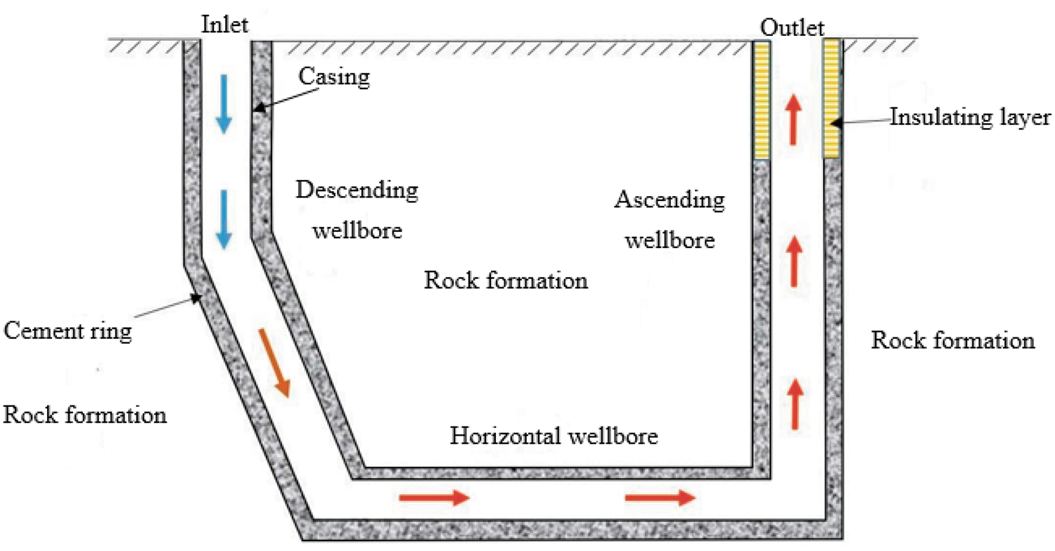
Schematic of the U-shaped docking well.
The U-shaped horizontal docking well uses a horizontal well and two vertical wells. To construct the well, a fiberglass casing is placed at the bottom of the straight well. Next, after cementing, a hole is formed by breaking the fiberglass casing with a reaming drill. Getting through the horizontal well and the vertical wells and putting the blind flange, an open hole packer, production casing string of the multiple-stage cementer into the bottom. Then the well is cemented and the cement sets. A small drill is then used to penetrate the multiple-stage cementer and the blind flange. After that, the two vertical wells are completely connected.
Characteristics
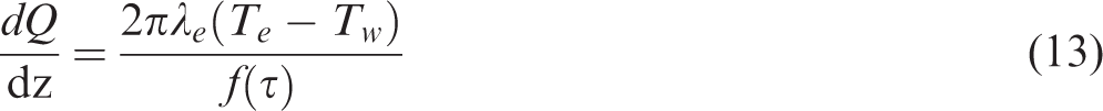
The low-temperature energy of a shallow ground layer can achieve only a low temperature, so it is necessary to use a heat pump to raise the temperature and heat a structure. Ground pipe heat pumps need a large area of land to embed their pipes. Also, this method has limited usefulness because high-rise buildings do not cover enough ground area to bury enough heat pipes. However, the temperature of a stratum 200–3000 m underground can reach dozens or hundreds of degrees celsius; this is insufficient to generate electricity, but its temperature grade is just under the heating range. If the stratum can be used for heating, the heating problems can be solved radically. Middle-depth geothermal heat extraction heating is similar to that of a shallow soil source heat pump. High-efficiency heat exchanger tubes can be positioned by drilling down to a middle-depth stratum. A cryogenic fluid medium can then be injected. In this way, the geothermal energy of the middle-depth stratum can be transferred to the cryogenic fluid in the tubes, which can then be used to heat a building (as shown in Figure 1). After its temperature has decreased, the artificial medium can be injected into the well again. This method also works in a deep heat-extraction formation, which is usually in rocks or sand without groundwater. The fluid flowing through the pipe does not contact the surrounding rocks and forms a closed circulation.
The best description of this type of process is that “heat is taken, but water is left.” It will not destroy the underground environment, cause land subsidence, or pollute the environment by emissions because it does not extract or process groundwater. At the same time, it protects geothermal resources and prolongs their service life.
Thermal calculation model for a heat absorbing well
Basic assumptions
The soil is well distributed, and its thermal properties remain constant throughout the heat transfer process. The effect of water transfer in the soil is minor enough to be ignored. The contact thermal resistance between the U-tube wall and the backfill material and between the backfill material and the soil is minor enough to be ignored. The initial temperature is the local average annual temperature. The influences of surface temperature fluctuations and the buried pipe depth on soil temperature are minor enough to be ignored. The bend at the bottom of the U-shaped tube is adiabatic despite the changing velocity distribution and direction of the fluid. The spacing between two vertical drill holes is wide enough that the effect of heat transfer between the holes can be ignored.
Mathematical model
One-dimensional steady heat transfer model of the wellbore. Suppose that a steady-state heat transfer occurs in the wellbore. In this assumption, the heat transfer is determined by the temperature of the outer wall of the cement casing, which is obtained by the unsteady thermal conductivity of the stratum and does not mean that the temperature in the wellbore remains constant over time. The schematic diagram of simplified heat transfer model is shown in Figure 2.
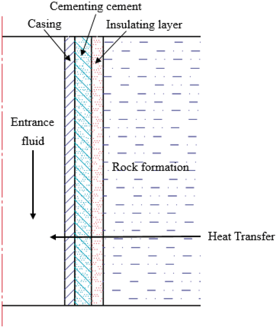
Schematic diagram of simplified heat transfer model.
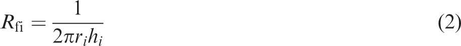
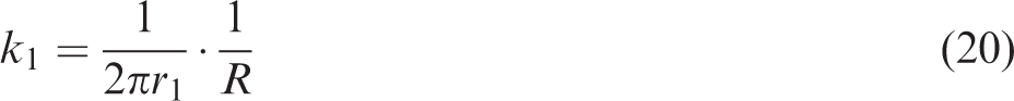
A one-dimensional steady heat transfer occurs between the center of the workpiece pipe and the outer diameter of the cement ring or the optional insulation layer. The total heat transfer formula is

The total thermal resistance of the proposed well from inside to outside comprises (1) convective heat transfer resistance, (2) the thermal resistance of the metal tube wall, (3) the thermal resistance of the cement ring, and (4) the thermal resistance of the thermal insulating layer.
(a) The calculation of convective heat transfer resistance is based on
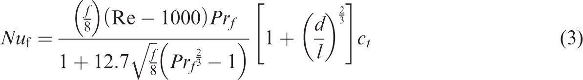

For liquid


where d is the pipe characteristic size (let d = 2ri) in meters, and λf is the thermal conductivity of the fluid in W/(m·K).
The experimental verification scope of equations (4)–(6) is Re = 2300 − 106 and Pr f = 0.6–105.
b) The calculation of thermal resistance is

One-dimensional unsteady heat conduction in the formation. The unsteady thermal conductivity of the formation in the same microelement with the steady-state heat transfer is

When initial condition τ = 0

When boundary condition
At the interface between the cement ring and the stratum where r = r3

At the interface between the insulation layer and the stratum where r = r4

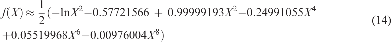
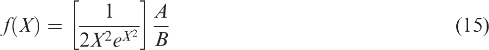
The results can be obtained by a semi-analytical method as follows
This project adopted the method recommended by the International Ground Source Heat Pump Association to calculate f(τ) in the model. The specific calculation method is as follows (Song and Kim, 2005).
Let
(b) when

and

Due to the steady heat transfer in the wellbore, there is a heat transfer balance between the wellbore structure and the stratigraphic interface, so

We can get

where k1 is the total heat transfer coefficient. Let
Model solution method
Divide the U-shaped horizontal docking well and the straight well concentric tube into N segments of equal length for subsection calculations: the bending part of the U-shaped well is a piecewise linear approximation. The relevant geological parameters are calculated by the working medium temperature and working medium that gave in the initial formation temperature. According to the flow direction of the working medium, each segment is calculated iteratively, and the temperature and heat transfer of each segment can be obtained. The heat transfer of the entire underground heat exchanger can also be obtained.
Calculation results and analysis
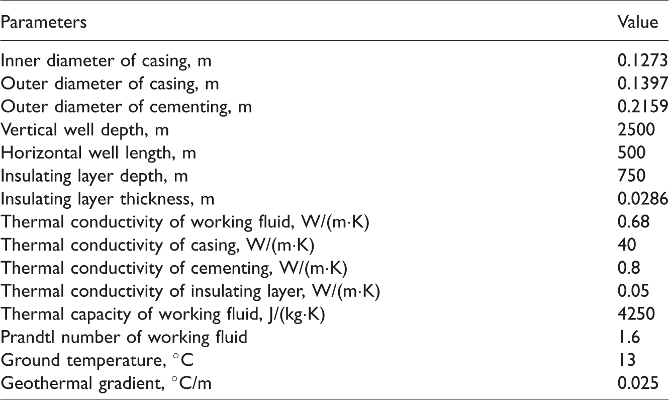
We simulated the 2500-m U-shaped horizontal butt pipe at the well depth using the predicted average physical parameters of the Yanchang Petroleum Group geothermal project and the logging temperature of the Xi’an Yuhua Enterprise Group Geothermal Well Formation Report. The basic parameters used for calculation is listed in Table 1.
Basic parameters used for calculation.
Absorbed heat analysis
The results show that the amount of heat removed from a geothermal well decreases over time. It can be seen in Figure 3 that although a geothermal well contains much heat, its initial heat output decreases rapidly, whereas in the middle and late stages the heat output reduces more gradually. Therefore, as a basis for evaluating a geothermal well’s heat extraction ability we set the calculated value of the heat transfer rate at less than 0.5% to more objectively show the well’s thermal capacity. This value was also used to design related schemes.
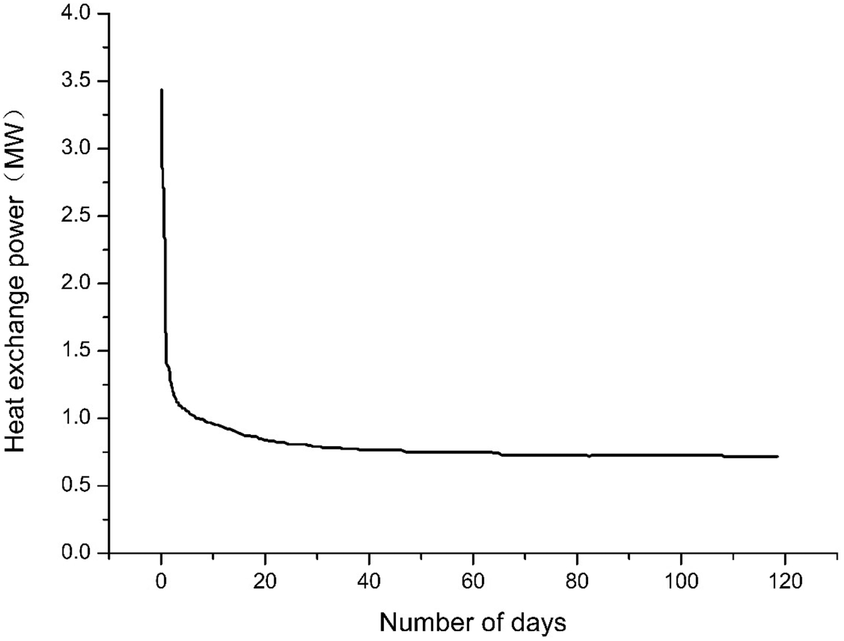
Change of heat transfer power over time under a full load operation of the U-shaped horizontal docking well. Under operating conditions, the inlet water temperature is 5°C, and the working medium flow rate is 80 m3/h.
The formula for calculating the rate of heat output reduction is

Key parameter analysis
Figures 4–7 show the results of different inlet and outlet water temperatures, heat exchange powers, and flow rates. As shown in Figures 4 and 5, in certain cases the flow rate of the proposed docking well increases almost linearly with increases in inlet and outlet water temperatures, and the heat exchange power decreases almost linearly with an increase in inlet water temperature. When the inlet water temperature is certain, with an increase in flow, the outlet water temperature decreases at a decreasing rate. The heat transfer rate increases with it, but its rate of increase decreases.
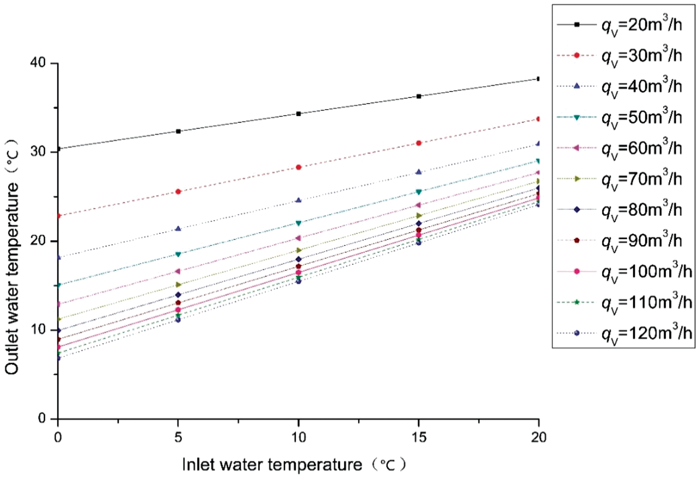
Relation between the inlet and outlet water temperatures of the proposed docking well at different flow rates.
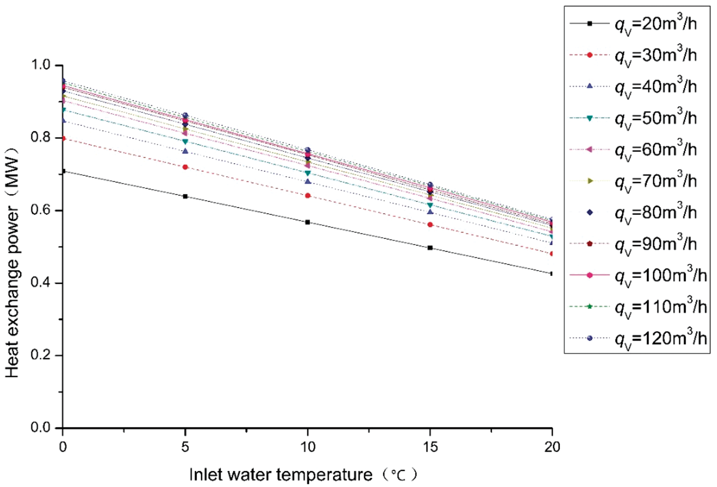
Relation between the heat exchange power and the inlet water temperature of the proposed docking well at different flow rates.
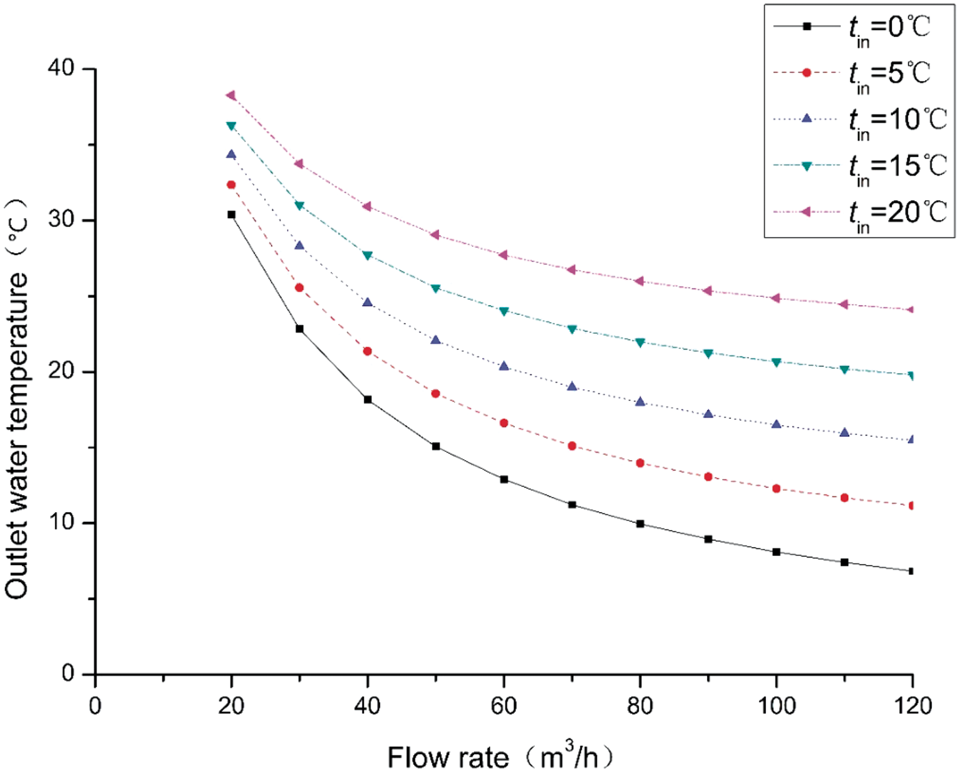
Relation between the outlet water temperature and the flow rate of the proposed docking well at different inlet water temperatures.
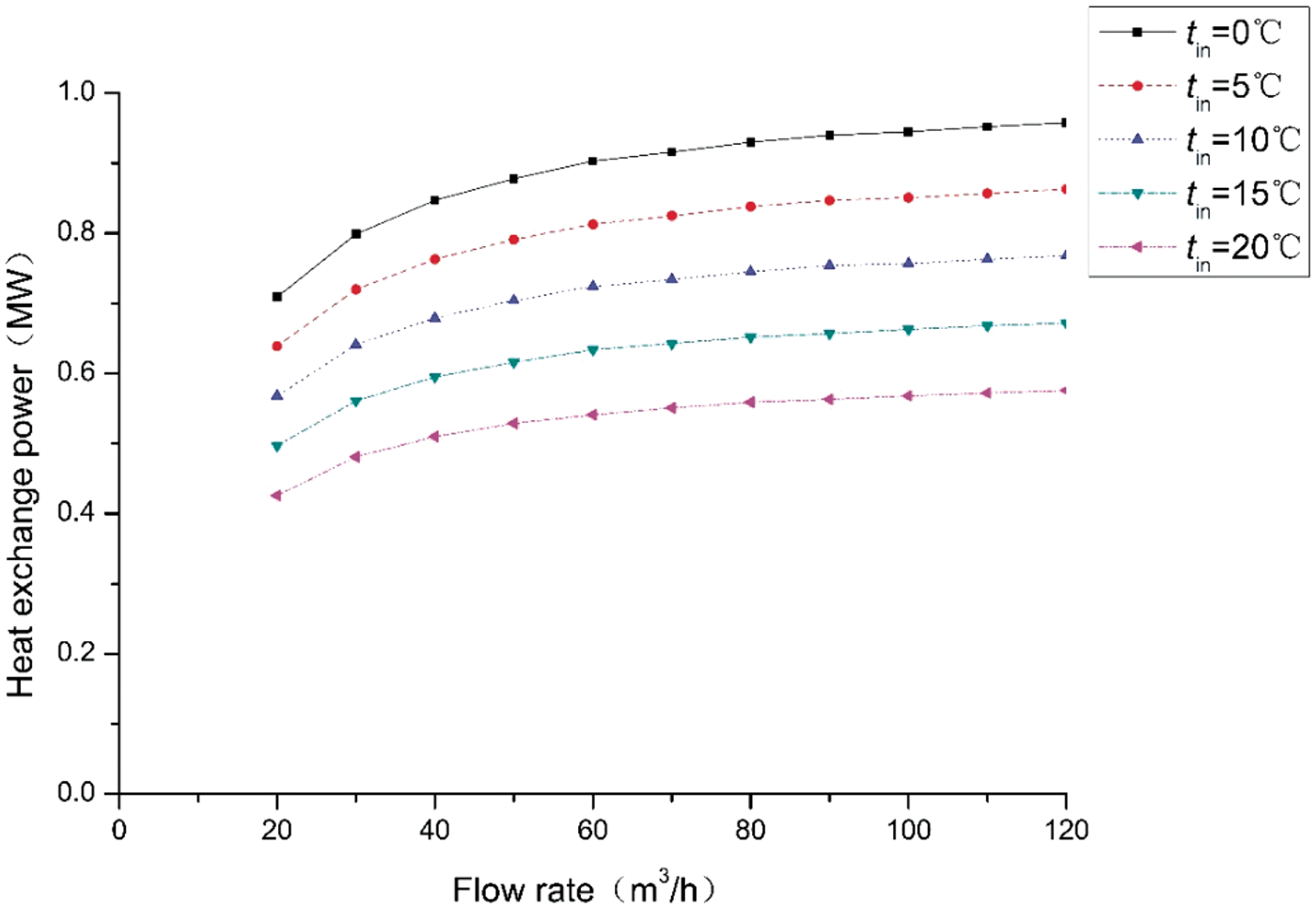
Relation between the heat exchange power and the flow rate of the proposed docking well at different inlet water temperatures.
Ground temperature recovery analysis
We used a numerical model of a middle-depth formation three-dimensional heat transfer of geothermal rock to determine how the temperature of the ground near the cement ring changes with time after a heating season ends. Figure 8 shows the temperature changes in the stratum near the cement ring over time at a depth of 2500 m underground. The results show that after a heating season, the temperature of the ground near the cement ring initially recovers quickly but later increases more slowly. The formation temperature at 2500 m recovered from 48.23°C at the end of the heating season to 80.49°C one year after the operation, which was close to the initial ground temperature of 80.66°C (a decrease of approximately 0.2°C).
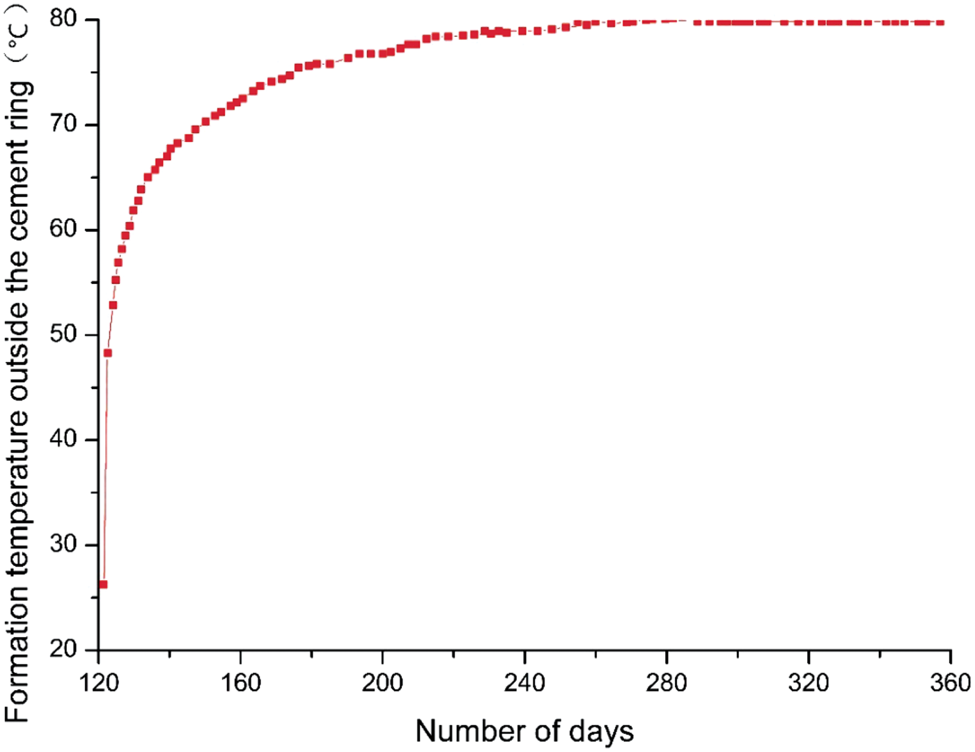
Formation temperature of the cement ring at a depth of 2500 m after heating stops.
In addition, according to the results calculated by this model, after the 121-d heating operation, the influence radius of the single thermal well on the surrounding formation temperature was approximately 5.3 m. It means that when designing heat-extraction wells, the designers should ensure that the distance between two wells is not less than 11 m to make full use of geothermal resources and guarantee a long term and effective functioning of the heat extraction system.
Formation thermal conductivity analysis
According to rock thermal conductivity data obtained in the Guanzhong basin in China, the minimum value was 1.528 W/(m·K) (mudstone data), and the maximum value was 2.985 W/(m·K) (sandstone data), with an average value of 2.294 W/(m·K). The conductivity from shallow to deep was between 1.5 and 3.0 W/(m·K), and the thermal conductivity of sandstone and mudstone differed little. Therefore, within the scope of this data, we simulated the heat transfer condition of the proposed docking well under thermal conductivities of different rock strata with an inlet water temperature of 15°C and a flow rate of 40 m3/h. The results are shown in Figures 9 and 10.
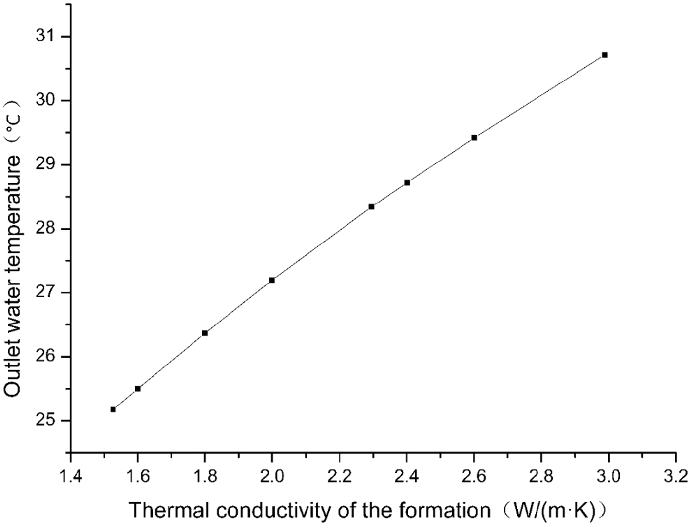
Relation between outlet water temperature and formation thermal conductivity with an inlet water temperature of 15°C and a flow rate of 40 m3/h using the proposed docking well.
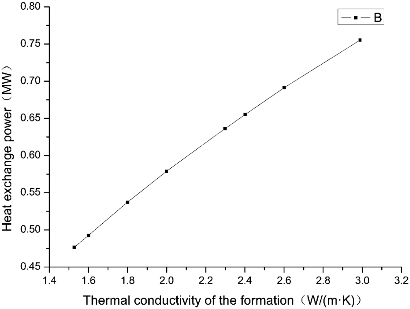
Relation between heat exchange power and formation thermal conductivity with an inlet water temperature of 15°C and a flow rate of 40 m3/h using the proposed docking well.
The results show that when
Due to the lack of actual thermal conductivity values of the drilling area in this project, we used an average value of 2.294 W/(m·K) as the formation thermal conductivity in the calculation.
Horizontal section analysis
The calculated results (Figures 11 and 12) show that when working 121 d when the horizontal section is 1000 m long, its outlet water temperature is 2.7°C higher than before, the total heat transfer power increases to 0.125 MW higher than before, and the horizontal section’s contribution to the total heat transfer power increases from 16% to 35%, which is close to that of the falling section.
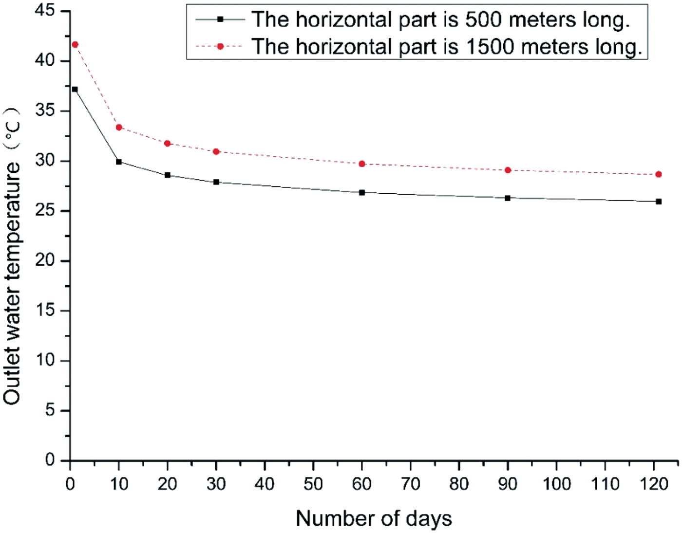
Comparison of outlet water temperatures over time for 500-m and 1000-m horizontal sections (working condition: tin = 15°C, and qv = 40 m3/h).
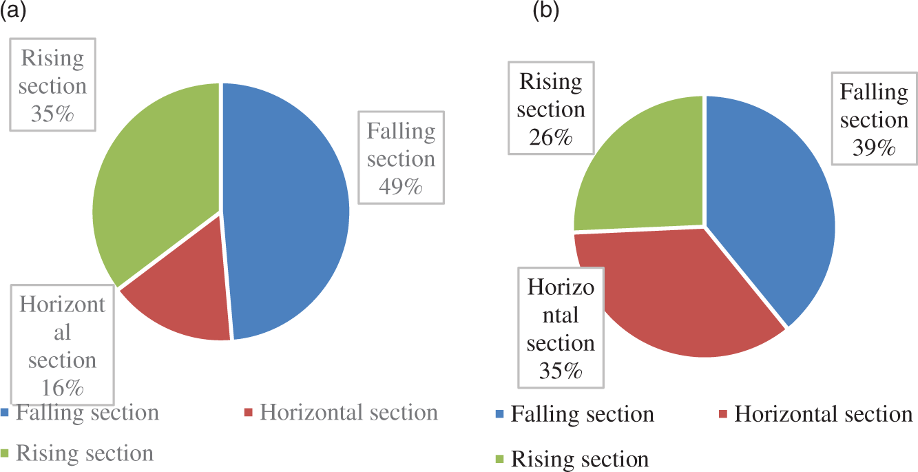
Heat transfer contributions of sections of the proposed docking well. (a) With 500-m horizontal section. (b) With 1000-m horizontal section.
It can be seen that as long as the outlet fluid temperature of the horizontal segment is lower than that of the formation temperature, the effective increase of the heat exchange area of the horizontal segment makes a major contribution to improving the heat transfer capacity of the proposed docking well. However, an increased horizontal length means increased drilling costs. Therefore, economic accounting must be carried out before construction.
Comparison with concentric casing heat extraction systems
The same heat transfer principle as the U-shaped docking well geothermal heat extraction system, the total thermal resistance of the concentric casing heat extraction system from inside to outside comprises (1) the inner tube convection between the fluid and the inner wall of the tube, (2) the tube wall heat conduction thermal resistance, (3) the heat resistance of the metal tube outer wall, (4) the pipe convective heat resistance between the fluid and the outer tube fluid, (5) the convective heat resistance of the outer tube wall, (6) the cement ring thermal resistance, and (7) the insulation layer thermal resistance. The basic parameters used for this calculation is listed in Table 2.
Basic parameters used for concentric casing heat extraction system calculation.
We analyzed and compared the two systems under the same physical properties, as shown in Figures 13 and 14.
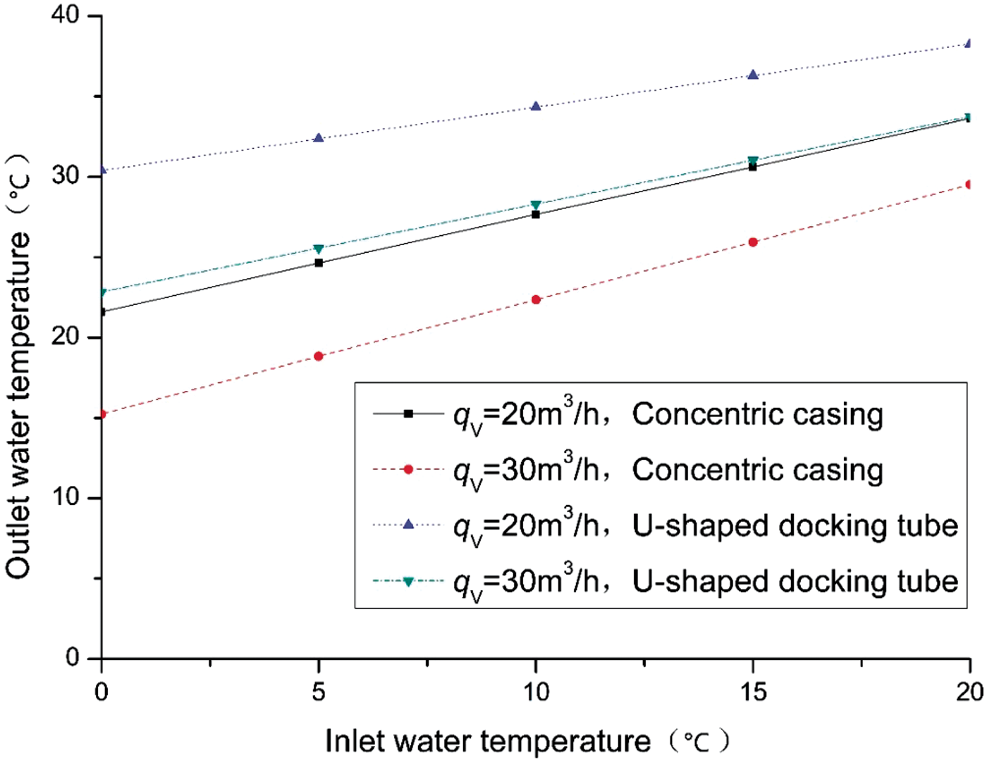
Relation between outlet water temperature and inlet water temperature for different systems.
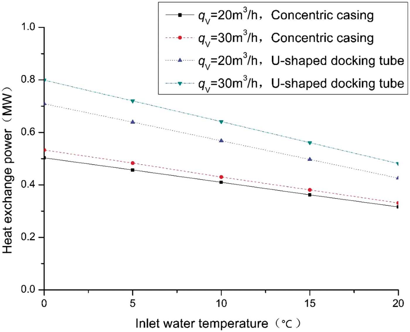
Relation between heat exchange power and inlet water temperature for different systems.
The results show that the variations in the outlet water temperatures and heat exchange powers of the concentric casing geothermal heat extraction system with the same working fluid flow rates and inlet water temperatures are basically the same as those of the proposed system. However, it is clear that the heat transfer effect of the proposed system is greater.
Conclusions
The U-shaped docking well geothermal heat extraction system uses a horizontal well and a vertical well. The best description of this type of process is that “heat is taken, but water is left.” The mathematical model of the U-shaped docking well was constructed and solved. The outlet temperature, the heat exchange power, and the length of the horizontal section are the key parameters of the proposed heat exchange system. These can be obtained by a mathematical model. Under different working conditions, when the inlet water temperature is constant, the outlet water temperature decreases with the increase of the working fluid flow rate, and the heat exchange power increases accordingly. The effective increase of the heat exchange area of the horizontal segment makes a major contribution to the improvement of the heat transfer capacity of the U-shaped horizontal docking well. The proposed geothermal heat extraction system is consistent with the qualitative law of the concentric casing system, but it is clear that the heat transfer effect of the U-tube is greater.
Therefore, further development of the docking technology of U-shaped buried pipes and economic analyses of the system are the key to the future improvement of the U-shaped docking well geothermal heat extraction system.
Footnotes
Declaration of conflicting interests
The author(s) declared no potential conflicts of interest with respect to the research, authorship, and/or publication of this article.
Funding
The author(s) disclosed receipt of the following financial support for the research, authorship, and/or publication of this article: This research was funded by the Natural Scientific Foundation of China (51674217), Yanchang Petroleum Group geothermal project (GJM18TLH0005).