
Abstract
Hydraulic fracturing is an efficiency approach to improve underground gas drainage. Although the interaction of fluid and coal has been comprehensively investigated in fracturing process and gas drainage process, fewer scholars have combined these two processes together and taken the gas–water two-phase flow into account, which brought a large deviation for design of hydraulic fracturing enhancing underground gas drainage. In this paper, we proposed a fully coupled hydraulic stress damage mathematical model considering gas–water two-phase flow, which can be used to simulate the whole process of hydraulic fracturing enhancing underground gas drainage. The coal seam is simplified as a dual-porosity single-permeability elastic media with elastic modulus reduce and permeability increase when encountered damage. The permeability and porosity serving as the coupling term is a function of stress, water/gas pressure, gas ad/desorption, and damage value. The proposed model was first verified by showing that the modeled gas flux agrees with the field data. The evolution laws of permeability and gas pressure during hydraulic fracturing enhancing underground gas drainage were studied and several influence factors were analyzed by accomplishing a series of simulations. Gas drainage can be effectively enhanced only when the hydraulic fracturing induced damage zone is breakthrough at drainage hole. After the coal seam is effectively fractured, the gas flux has a decline–incline–decline tendency with increasing of drainage time. The breakthrough time of damage zone increases linearly with coal seam elastic modulus, increases exponentially with vertical stress and borehole spacing, and decreases exponentially with injecting pressure.
Keywords
Introduction
As a kind of fossil energy resources, coal plays an important role in the development of the world economy. However, the coal exploitation process is often accompanied by the occurrence of mine gas disasters, such as coal and gas outburst and gas explosion, resulting in a large number of casualties and property losses (Xu et al., 2006, 2017b). Exploitation practice has proved that underground gas drainage is an effective way to prevent gas disaster (Li et al., 2016b). Due to the complex geological structure, the permeability is extremely low in coal seam with high gas content and outburst danger, which restricts the efficiency of gas drainage (Lama and Bodziony, 1998; Li et al., 2016b; Lin, et al., 2018; Liu, et al., 2017; Zhu et al., 2013). How to increase the permeability of coal seam is a problem to be solved urgently in safety mining. The permeability improvement methods have been put forward, such as protection layer mining, destress blasting, liquid CO2 phase transition cracking, and hydraulic slotting (Cai et al., 2007; Lu et al., 2009; Xie et al., 2015; Zhao et al., 2016; Zhu et al., 2013). However, these methods have their limitations, for instance, protective layer mining is only suitable for multiple coal seams, destress blasting may likely induce gas outburst, and the cracking scope of liquid CO2 phase transition is too small to effectively increase permeability. Hydraulic fracturing produces a series of artificial fracture networks by injecting high-pressure fluid into the reservoirs, so as to improve the reservoir permeability (Huang et al., 2012; Wang et al., 2014, 2015). In recent years, hydraulic fracturing has been applied to enhance gas drainage in low permeability coal seam, and has obtained great success in field practice (Bjerrum et al., 1972; Li et al., 2015; Yuan et al., 2015). Hydraulic fracturing enhancing underground gas drainage is a complex process involving the interaction of coal mass deformation and failure/damage, gas ad/desorption, water and gas migration (Xu et al., 2017). As far as the current research methods are concerned, laboratory tests can difficult reproduce the whole hydraulic fracturing enhancing underground gas drainage process. Hence, it is particularly significant to propose an accurate mathematical model and use numerical simulation method to reproduce this process (Shen and Standifird, 2017).
In terms of hydraulic fracturing, mathematical equations of rock deformation and fluid flow are separately introduced to simulate crack propagation by finite element method firstly (Adachi et al., 2007; Boone et al., 1986; Papanastasiou, 1997; Zhu and Tang, 2004). Hossain and Rahman (2008) pointed out that crack growth requires the treatment of fluid flow and structural deformation coupling phenomena. The models coupled with geomechanics and coal mass were then proposed (Ji et al., 2009; Olovyanny, 2005). The thermal impact on coal and gas/water interactions cannot be ignored especially in deep buried reservoir. In this regard, Li et al. (2012), (2016b) and Yan and Zheng (2016) established several models considering thermal effect for hydraulic fracturing and solved by finite element method. Meanwhile, scholars realized that hydraulic fracturing involves discontinuous deformation and failure of coal and rock. Wang et al. (2014) and Wrobel and Mishuris (2015) simulated hydraulic fracturing using particle flow method. Furthermore, Yan et al. (2016) proposed a hydromechanical-coupled model and simulated hydraulic fracturing by combining finite-discrete element method. Gas drainage simulations have also been carried out (Li et al., 2017). Wang et al. (2017) proposed flow-solid coupling model and analyzed influencing factors of gas migration in coal seam. Xue et al. (2017a) built a thermo-hydro-mechanical model for controlling the pre-mining gas drainage with slotted boreholes. So far, hydraulic fracturing and gas drainage are separately studied although these processes have been widely simulated, which makes it difficult to reproduce the whole hydraulic fracturing enhancing underground gas drainage process. Also, the gas–water two-phase flow and the dual-porous characteristic of coal seam are seldom taken into consideration in their proposed models.
In this work, we extend previous models and propose a fully coupled hydraulic stress damage (HSD) model with two-phase flow including coal deformation and damage, gas ad/desorption, diffusion and seepage, and water seepage governing equations. The damage distribution was used to indirectly present the propagation of cracks in coal seam. Then, we embedded governing equations into Comsol with Matlab software to evaluate the whole process of hydraulic fracturing enhancing underground gas drainage. The proposed model is verified by comparing the results of field test with numerical simulation. The variations of coal seam elastic modulus, permeability, and gas pressure are numerically investigated, as well as several influencing factors including elastic modulus, vertical stress, borehole spacing, and fluid injecting pressure, to better understand the rules of gas/water migration, coal deformation and damage evolution during hydraulic fracturing enhancing underground gas drainage process.
The HSD coupled model
In the following, a set of field governing equations will be defined to govern the coal deformation and damage, the gas and water migration. According to the existence and migration law of gas and water in coal seam, the following hypotheses are given (Fan et al., 2016; Li et al., 2016a; Wu et al., 2011; Xia et al., 2014): (1) the representative element volume (REV) within coal seam is used for governing equations; (2) coal seam is a dual-porosity, single-permeability elastic material with microporous matrix and macroporous fractures; (3) water exists and migrates only in fractures, and gas exists and migrates in both pores and fractures; (4) hydraulic fracturing induced crack (damage) will increase the channel of fluid flow, and coal seam permeability will rapidly raise in the way of jumping; (5) the gas drainage process is treated as a tandem of three steps: firstly, gas desorbs from the pore wall in coal matrix satisfying the Langmuir adsorption law; secondly, gas diffuses from coal matrix to fractures satisfying Fick’s law; thirdly, gas seepages from fractures to drainage borehole satisfying Darcy’s law, as shown in Figure 1; (6) gas agrees with the ideal gas state equation and its volume force can be ignored; and (7) tensile stress is positive.
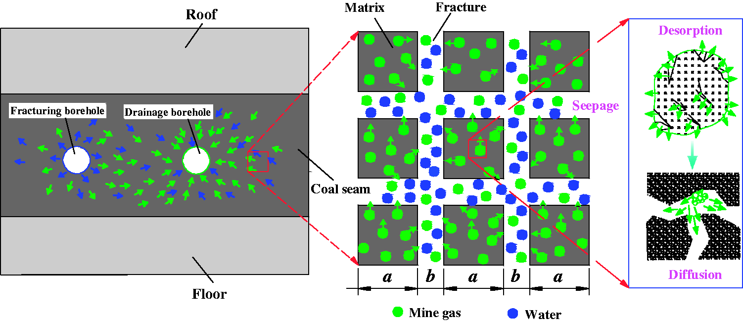
Gas and water migration during the hydraulic fracturing enhancing underground gas drainage process, where a is the matrix length and b is the fracture aperture (after Li et al., 2016a; Fan et al., 2016).
Governing equation of hydraulic field
Coal seam is a kind of layered combustible mineral characterized by a typical dual-porosity system filling with gas, groundwater, and fracturing water. The coal matrix contains free gas and adsorbed gas components. The gas content in matrix can be defined as (Li et al., 2016a)

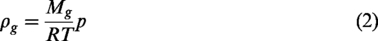
According to the ideal gas state equation, gas density is defined as
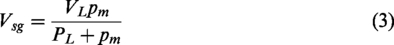
The absorbed gas volume per unit mass can be expressed as a Langmuir equation
As assumed in the hypothesis, gas is originally in dynamic equilibrium state of adsorption and desorption. The gas pressure in coal matrix is equal to that in fractures. Both hydraulic fracturing and gas drainage will change the gas pressure in fracture and then break the dynamic equilibrium state. For gas drainage, the adsorbed gas will desorb and transport into the fracture system by means of diffusion under the concentration gradient. According to the Fick diffusion law, the conservation of gas mass in coal matrix can be described as (Fan et al., 2016)

By substituting equations (1)–(3) into equation (4), the gas migration equation in coal matrix can be obtained

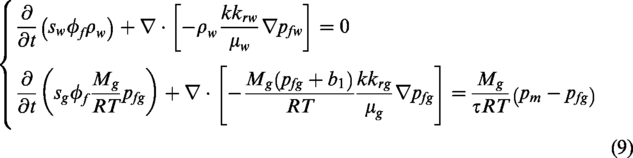
In the process of hydraulic fracturing enhancing underground gas drainage, coal seam contains large amount of ad/desorbed gas coexisting with fracturing water and groundwater. Hence, the fluid flow in coal seam is a kind of gas–water two-phase flow. Coal matrix provides a uniformly distributed gas mass source for the fracture system. The mass conservation equation in fracture will be (Fan et al., 2016)
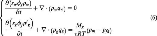
According to the generalized Darcy law of two-phase flow and considering the gas Klinkenberg effect (Zhu et al., 2007), the gas and water velocity in fracture are:
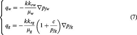
Corey (1954) proposed a calculative equation for relative permeability, which was proved by Clarkson and Qanbari (2015)
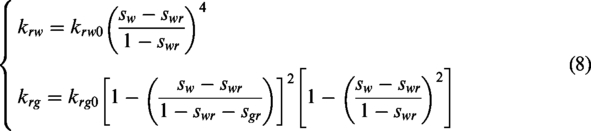
By substituting equation (6) into equation (7), the governing equations of hydraulic field in fracture system can be derived as
Governing equation of stress field
Coal seam is a dual-porosity material, and its mechanical properties are influenced by pores and fractures and the contained fluid. The total strain of coal seam is the sum of strains induced by stress, gas pressure, water pressure, and gas de/adsorption induced shrinkage/swelling, which can be expressed as (Li et al., 2016a; Wu et al., 2011; Xia et al., 2014)

Based on the elastic mechanics, the equations of strain–displacement relation and static stress equilibrium relation in coal seam can be defined as
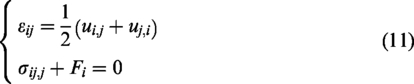
Combining equations (10) and (11), a modified Navier equation, namely the governing equation of stress field, can be obtained

Governing equation of damage field
Coal and rock are heterogeneous materials. We assume that the mechanical parameters of REV obey the Weibull distribution. The function of probability density is defined as (Zhu et al., 2013)

The impact of hydraulic fracturing on coal properties mainly includes two aspects: elastic modulus reduction and fracture permeability increase caused by physical damage, which are presented in the damage variable of equations (14) and (22), respectively. The cracks in the damaged area of coal seam after hydraulic fracturing are much developed, which will result in the fracture permeability rising (Zhu et al., 2013). Therefore, the coal damage zone, namely the elastic modulus decreasing zone, can be basically regarded as the zone of hydraulic fracturing.
Under the uniaxial compressive and tensile stress conditions, the elastic constitutive relation of an REV is shown in Figure 2.
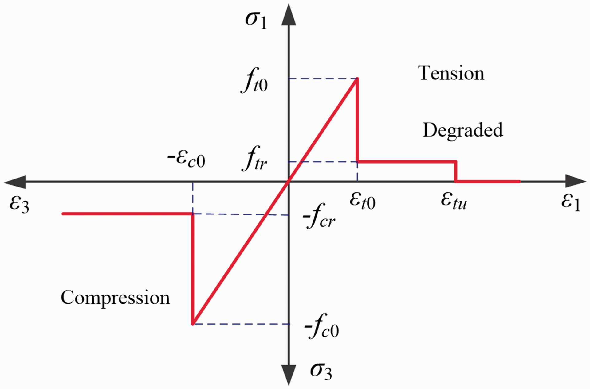
Elastic damage constitutive model of coal under uniaxial stress (after Xu et al., 2006).
Based on the elastic damage theory, the elastic modulus decreases linearly with damage variable (Fan et al., 2017)

When the REV is confronted with tensile stress, the maximum tensile stress criterion is chosen as the strength criterion for the elements

In this case, the damage variable can be defined as (Fan et al., 2017; Xu et al., 2006)
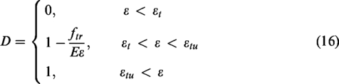
When the REV is confronted with compressive stress state, the Mohr–Coulomb criterion is chosen as the strength criterion for the elements
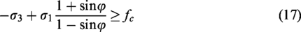
The damage variable in compression can be defined as (Xu et al., 2006; Fan et al., 2017)
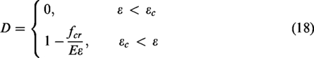
From equations (16) and (18), the damage variable is in the interval (0∼1). The maximum tensile stress criterion is first applied to judge whether the tensile damage of the elements or not. When the element is not damaged, the Mohr–Coulomb criterion is then applied.
Equation of coupling terms
Pores and fractures are the main storage and migration place for gas and water in coal seam, while the permeability is an important parameter for gas and water transportation. The variation of porosity and permeability is closely related to the stress imposed to coal seam and the inherent characteristics of coal seam. Based on our previous work, matrix porosity can be described as (Fan et al., 2016; Li et al., 2016a)

The fracture porosity can be defined as (Wu et al., 2011)
The cubic law is adopted as the relationship between fracture permeability and porosity in coal seam:
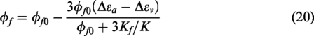
Substituting equation (20) into equation (21), and considering the rising effect induced by fracturing damage and the direction of permeability in coal seam, we can obtain
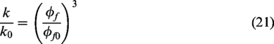
Combining equations (5), (9), (12), (14), (19), (20), and (22), we propose a fully coupled HSD model for hydraulic fracturing enhancing underground gas drainage. The model is consisted of several partial differential governing equations, which are difficult to solve theoretically because of spatiotemporal nonlinearity. Therefore, we implement them into COMSOL with MATLAB (CwM) to obtain numerical solution (COMSOL AB, 2012). This finite element method approach requires that the damage state and the damage-induced alteration of elastic modulus and permeability are continually updated with new damage occurs. Figure 3 presents a flow chart for this coupled modeling approach. The basic procedures are summarized as follows:
Solving process of the hydraulic stress damage coupled model.
After the studied geometry has been built, the model is discretized into a set of microscopic elements (REVs). Then Monte–Carlo method is utilized to generate the initial mechanical distribution by equation (13). The initial parameters are assigned to REVs as well as the stress and hydraulic boundary conditions. The hydraulic fracturing is a transient process, so that the duration of this process is defined and divided into several steps.
For the first step i = 1, a coupled calculation is performed using solid module and partial differential equation (PDE) module of Comsol Multiphysics by equations (9) and (12). And the effective stresses and pore pressure for each of the REVs are computed.
Then, the damage tensor is calculated using equations (16) and (18). Furthermore, if new damage emerges compared with the former damage tensor, the tensors for the elastic modulus and the permeability are modified following equations (14) and (22).
The continuum finite element model with the updated material parameters is used to define a new equilibrium and steps (ii) and (iii) are repeated to examine the damage state. During the hydraulic fracturing process, fractures will propagate along the damage zone. If there is no new damage emerges, the next time step is loaded until the maximum fracturing time is reached.
Finally, when the fracturing is finished, we set gas drainage duration and change the boundary condition, including non-flow condition around fracturing holes and drainage pressure condition around drainage holes, to simulate the gas drainage process.
According to this flow chart, the combined model is programmed using MATLAB and Comsol Multiphysics.
Verification of the HSD-coupled model
Physical geometry model and solving conditions
The Mabao coal mine located in Shanxi Provence, China is a highly gassy mine with an approved production capacity of 1.5 million tons per year. The main minable seams are 8#, 9#, and 15# coal seams. The panel 15108 recovers coal seam 15# with an average thickness 4.8 m, dip angle 10–12°, and buried depth 640 m. The working face width of panel 15108 is 180 m and the strike length is 1627 m. The roof lithology of the coal seam 15# is mudstone and fine sandstone, while the floor lithology is mudstone. The low permeability of coal seam 15# leads to difficulty of gas drainage, resulting in gas concentration exceeds allowable value at the upper corner of working face. Therefore, hydraulic fracturing is carried out to increase permeability and promote gas drainage.
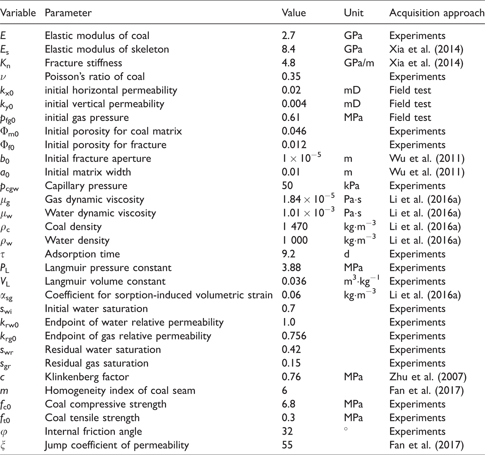
The plane strain geometry with two dimensions is adopted to reproduce the hydraulic fracturing enhancing underground gas drainage process. As shown in Figure 4, the model size is 44 m × 10.8 m. The thickness of coal seam, roof, and floor are 4.8 m, 3 m, and 3 m, respectively. Hydraulic fracturing will usually cause destruction and collapse of the coal mass around fracturing borehole. So, the adjacent borehole is generally used for gas drainage. We arrange one drainage borehole, two control boreholes (for crack guidance), and two fracturing boreholes in the coal seam. The borehole spacing is 8 m and the diameter is 0.11 m. The initial horizontal and vertical permeability in coal seam are 0.02 mD and 0.004 mD, respectively. In the original state, gas pressure is 0.61 MPa. For the physical model, a slip boundary is applied to both bottom and left sides. The load from the weight of overlying strata with an average density of 2500 kg·m−3 is adopted on the top boundary. The horizontal stress is applied to the right boundary. Meanwhile, the floor and roof stratum are insulated for gas and water migration. The fluid injecting pressure of hydraulic fracturing is 20 MPa, while the drainage pressure is 30 kPa. As listed in Table 1, other parameters used in the numerical simulations are taken from the experimental results and related literatures (Fan et al., 2017; Li et al., 2016a; Wu et al., 2011; Xia et al., 2014; Zhu et al., 2007).
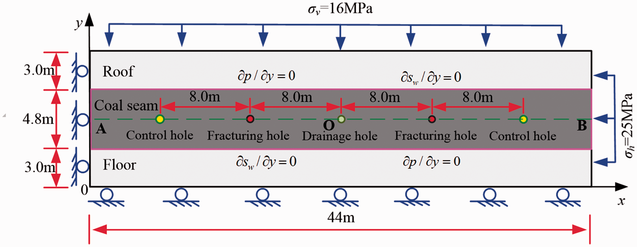
Physical model of hydraulic fracturing enhancing gas drainage.
Parameters used in simulation.
A green line A–B and point O as the observation reference was drawn to analyze the variations of permeability and gas pressure during the hydraulic fracturing enhancing underground gas drainage process (Figure 4). The location of point A and B are (0 m, 5.4 m) and (44 m, 5.4 m), respectively. The point O (22 m, 5.4 m) is in the middle of line A–B.
According to equation (8) and parameters in Table 1, the relative permeability curves of gas and water phases are shown in Figure 5. The following simulations are carried out using the curves.
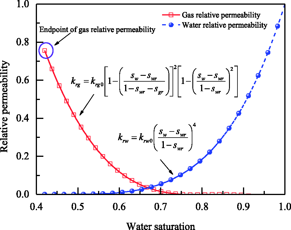
Relative permeability curves of gas and water.
Model verification
The elastic modulus distribution in coal seam after different fractured durations is shown in Figure 6. Coal seam is a heterogeneous porous material and its elastic modulus obeys the Weibull distribution. High-pressure fluid flows into coal seam through the fracturing borehole, resulting in tensile and shear damage. Generally speaking, under the influence of geological structure, the horizontal stress in coal seam is greater than vertical stress. The coal mass on the both sides of fracturing borehole is damaged firstly due to the large subjected tensile stress. The permeability of damage zone dramatically increases to a high value. Driven by high permeability and large pressure gradient, the fracturing fluid rapidly penetrates into this damage zone. Later, the coal around the damage zone will continually rupture. With the increase of fracturing time (tf), the damage zone gradually expands and this expansion along the horizontal direction is much faster than vertical direction, which will result a horizontal strip shape of the damage zone. After fractured 1.5 h, 2.0 h, 2.5 h, and 3.0 h, the expansions in the horizontal direction of single fracturing borehole are 11 m, 14 m, 15.5 m, and 16 m, respectively. The damage zone between the two fracturing boreholes will be connected at the drainage borehole when tf is more than 2.5 h.
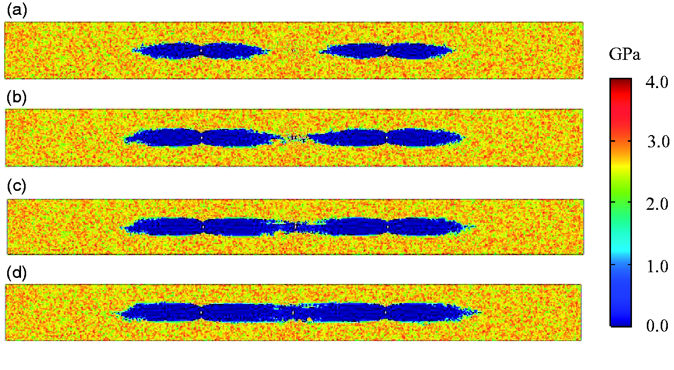
Elastic modulus distribution in coal seam, where tf is the fracturing time. (a) tf = 1.5 h, (b) tf = 2.0 h, (c) tf = 2.5 h and (d) tf = 3.0 h
The horizontal permeability variation on reference line A–B after fractured different time is displayed in Figure 7, which appears that the permeability variation has a wave shape. High permeability near the drainage borehole can promote gas migration. In this term, high permeability induced by the damage breakthrough at the drainage borehole is the guarantee of efficiency gas drainage. In Figure 7, the permeability is relatively low near the drainage borehole when fractured 2.0 h, which approximately equals to the initial permeability 0.02 mD. The permeability increases rapidly when fractured 2.5 h, reaching more than 0.8 mD. And the maximum permeability is 54.9 times higher than the initial permeability. However, as fracturing time continues to increase, the permeability of coal seam near the drainage borehole increases slowly. So, we can consider that the fracturing time 2.5 h is the shortest time for effective fracturing in Mabao coal mine. We define this shortest time as breakthrough time. After fractured 2.5 h, we changed the boundary conditions of the drainage and fracturing boreholes to simulate gas drainage, and compared the results with the field measured data.
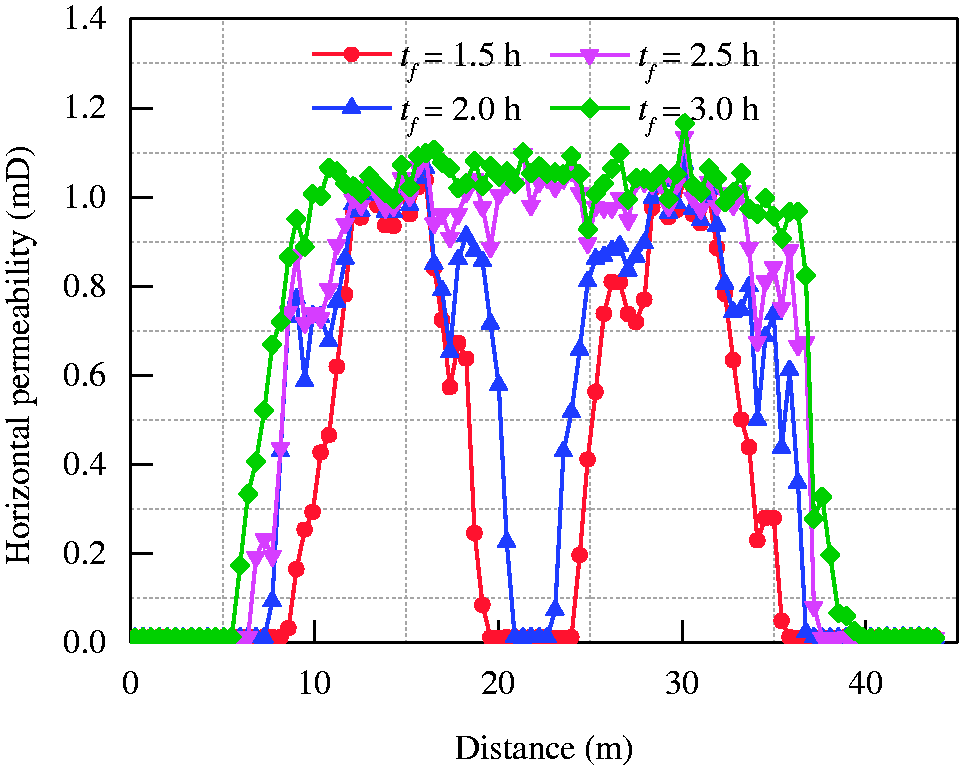
Horizontal permeability on line A–B after fractured different time.
The field test was carried out in Mabao coal mine. Boreholes were drilled on the coal wall of the roadway in panel 15108 according to arrangement in Figure 4. The diameter and length of the boreholes are 113 mm and 50 m, respectively. The sealing length of fracturing borehole is 20 m, while the sealing length of control and drainage borehole is 8 m. The boreholes are sealed immediately after drilled using grouting method, and the seal ring is added to ensure good sealing. As shown in Figure 8, the hydraulic fracturing equipment includes high-pressure pump, liquid mixing tank, fluid pipe, seal device, meters, and other relevant parts. High-pressure pump is an YL400/315 type plunger pump with rated pressure of 50 MPa. The liquid mixing tank is specially made for underground fracturing. The pipe is a rubber tube with inner diameter and outer diameter of 0.045 m and 0.065 m, respectively. When the preparation was finished, we carried out hydraulic fracturing with an initial injecting pressure of 15 MPa. After the coal wall around fracturing borehole was wet, we gradually increased the pressure to 20 MPa, and then kept it stable. The fluid injection was stopped when the injecting pressure declined to 7.5 MPa with fluid rushing out from the drainage borehole. It finally spent 2 h 40 min to fracturing, which approaches the 2.5 h of numerical simulation. Then, we began to drainage gas from coal seam by connecting drainage boreholes and pumping system. The drainage pressure was set as 30 kPa, and the gas flux was recorded in real time.
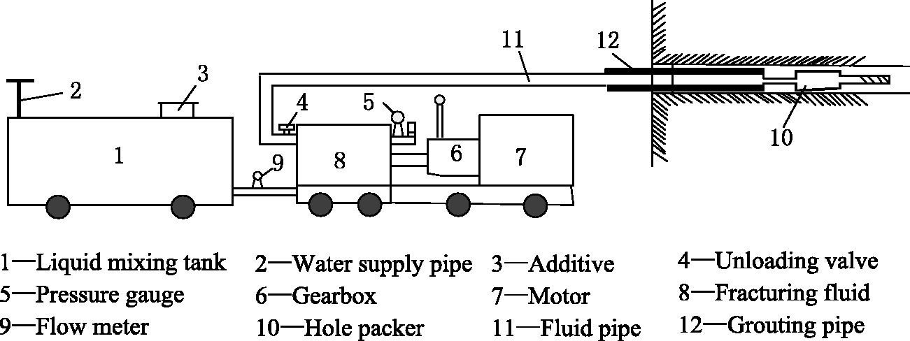
Schematic of hydraulic fracturing equipment.
The gas flux of field test and numerical simulation is shown in Figure 9. With increasing of drainage time, the gas flux has a decline–incline–decline tendency. In the early gas drainage stage, free gas in coal seam will gather around the drainage borehole driven by high-pressure injecting fluid. This amount of free gas is first extracted out, leading to a relatively high gas flux on the first day, with 95.88 m3·d−1 of the simulation and 119.82 m3·d−1 of the field test. The water flux on the first day is relatively low, with 0.2846 m3·d−1 of the simulation and 0.1866 m3·d−1 of the field test. After that, the fracturing water and groundwater continually flow into the drainage borehole. The water flux increases to the maximum value with 0.4884 m3·d−1 of the simulation and 0.3804 m3·d−1 of the field test. As the water in coal seam is discharged, the water relative permeability and the water flux decreases. The gas migration channel gradually unblocks to increase the gas relative permeability. A large amount of adsorbed gas desorbs and migrates into drainage borehole through fractured cracks, which induces a rapid rising of gas flux. The maximum values of simulation and field test are 145.54 and 127.15 m3·d−1 respectively. With the reduction of gas pressure in coal seam, the pressure gradient decreases gradually, as well as the gas flux. The field measured gas flux in 28 days is 22.89–126.57 m3·d−1 with an average of 63.79 m3·d−1. After 20 days’ drainage, the average water flux is extremely low, almost equal to zero. The overall trend and values measured in field are in accordance with the simulated result, which shows the accuracy of proposed model.
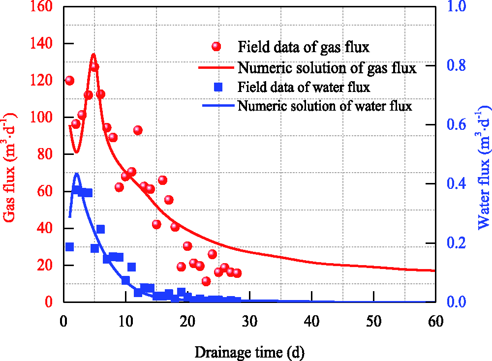
Fluid flux of field test and numerical simulation.
Numerical simulations of hydraulic fracturing enhancing underground gas drainage
Effect of effective fracturing on gas drainage
As revealed in Model verification section, the coal seam near the drainage borehole cannot be effectively fractured until fracturing 2.5 h. The results of gas drainage after fractured 2.0 h and 2.5 h are comparatively analyzed. The gas pressure in coal seam reduction by 20% is considered as a criterion for the influence radius of gas drainage. In the coal seam 15# of Mabao coal mine, the initial gas pressure is 0.61 MPa and the critical gas pressure is 0.488 MPa. The maximum influence radius occurs in horizontal direction. As shown in Figure 10, the gas pressure decreases slowly under the condition of noneffective fracturing. When the gas drainage time td = 10 d, 30 d, and 60 d, the maximum influence radius is 0.8 m, 1.3 m and 1.6 m, respectively. While the gas pressure reduces rapidly after effectively fractured, and the maximum influence radius is 3.2 m, 7.8 m, and 14.8 m when td = 10 d, 30 d, and 60 d, respectively.
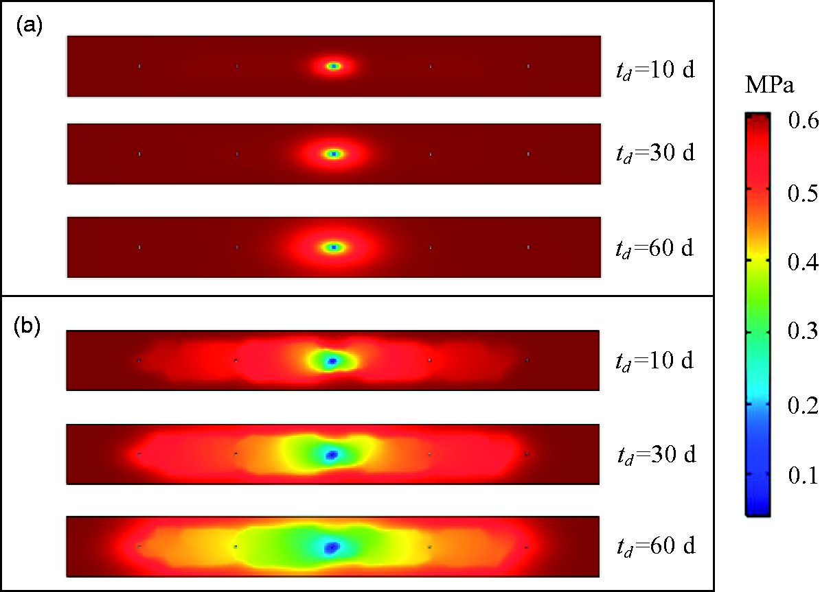
Gas pressure distribution in coal seam: (a) non-effectively fractured with fracturing time tf = 2.0 h, (b) effectively fractured with fracturing time tf = 2.5 h.
Gas pressure on line O–B is taken out to better understand the rules of gas drainage enhanced by hydraulic fracturing, as shown in Figure 11. With increasing of drainage time, the gas pressure in coal seam reduces, especially around the drainage borehole. When the coal seam is fractured 2.0 h (tf = 2.0 h), the gas pressure at the 5 m position from the drainage borehole is 0.6053 MPa, 0.6029 MPa, and 0.5935 MPa after 10, 30, and 60 days’ gas drainage. Compared with the initial value 0.61 MPa, gas pressure only reduces by 0.77%, 1.16%, and 2.71% respectively. In contrast, when fracturing time tf = 2.5 h, the gas pressure of td= 10 d, 30 d, 60 d is 0.5257 MPa, 0.4499 MPa, and 0.3894 MPa, reducing by 13.82%, 26.25%, and 36.16%, respectively. The gas pressure of tf = 2.5 h is much smaller than that of tf = 2.0 h, which explains that the importance of damage zone breakthrough at the drainage borehole for efficient gas drainage.
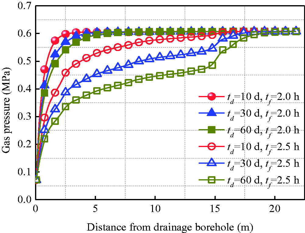
Gas pressure on the reference line O–B.
Influencing factors analysis
The success of hydraulic fracturing is largely dependent on the design of technical parameters and the in situ conditions in a given coal seam. Li et al. (2010) divided the influencing factors into technical factors (injecting pressure, borehole spacing, fracturing time, borehole length, sealing method, and fracturing equipment) and geological factors (the mechanical properties, geostress in coal seam). Due to the 2D geometry, factors of borehole length, sealing method, and fracturing equipment will not be discussed here. In the subsequent sections, a series of simulations are conducted to gain insight into the influence of injecting pressure, borehole spacing, vertical stress, and elastic modulus of coal seam on the hydraulic fracturing enhancing underground gas drainage process.
Borehole spacing
Borehole spacing is one of the key parameters during hydraulic fracturing enhancing gas drainage. As it is well known, small borehole spacing may increase the workload of drilling and fluid injection. Besides, large borehole spacing may cause the difficult of damage zone breakthrough and reduce the efficiency of gas drainage. In the following, we define the effective fracturing radius as the horizontal radius of the permeability increasing area on one side of the fracturing hole. As shown in Figure 12(a), when the borehole spacing is 10 m, the effective fracturing radius of tf = 2.5 h is 7.34 m, which is less than borehole spacing and the damage zone cannot be connected at the drainage borehole. The coal seam permeability near the drainage borehole is approximately equal to initial permeability. When borehole spacing is 4 m, 6 m, and 8 m, the damage zone break through drainage borehole, and the permeability will increase rapidly with a maximum value of 1.1425 mD near the drainage borehole. In Figure 12(b), when borehole spacing is 4 m, 6 m, 8 m, and 10 m, the gas pressure of td = 60 d at the position of 8 m from drainage borehole is 0.268 MPa, 0.299 MPa, 0.346 MPa, and 0.582 MPa, respectively. This indicates that gas pressure of borehole spacing 10 m only drops a small amount, because the permeability near drainage borehole is too low to drive gas moving into drainage borehole. The breakthrough time is defined as the duration of fracturing induced damage zone connecting at the drainage borehole. We obtained the breakthrough time of different borehole spacing, as shown in Figure 12(c). By fitting with the least square method, the breakthrough time has an exponential increasing relationship with borehole spacing. In Mabao coal mine, we imply that the coal seam can be effectively fractured within 3 h only when the borehole spacing is less than 8.58 m.
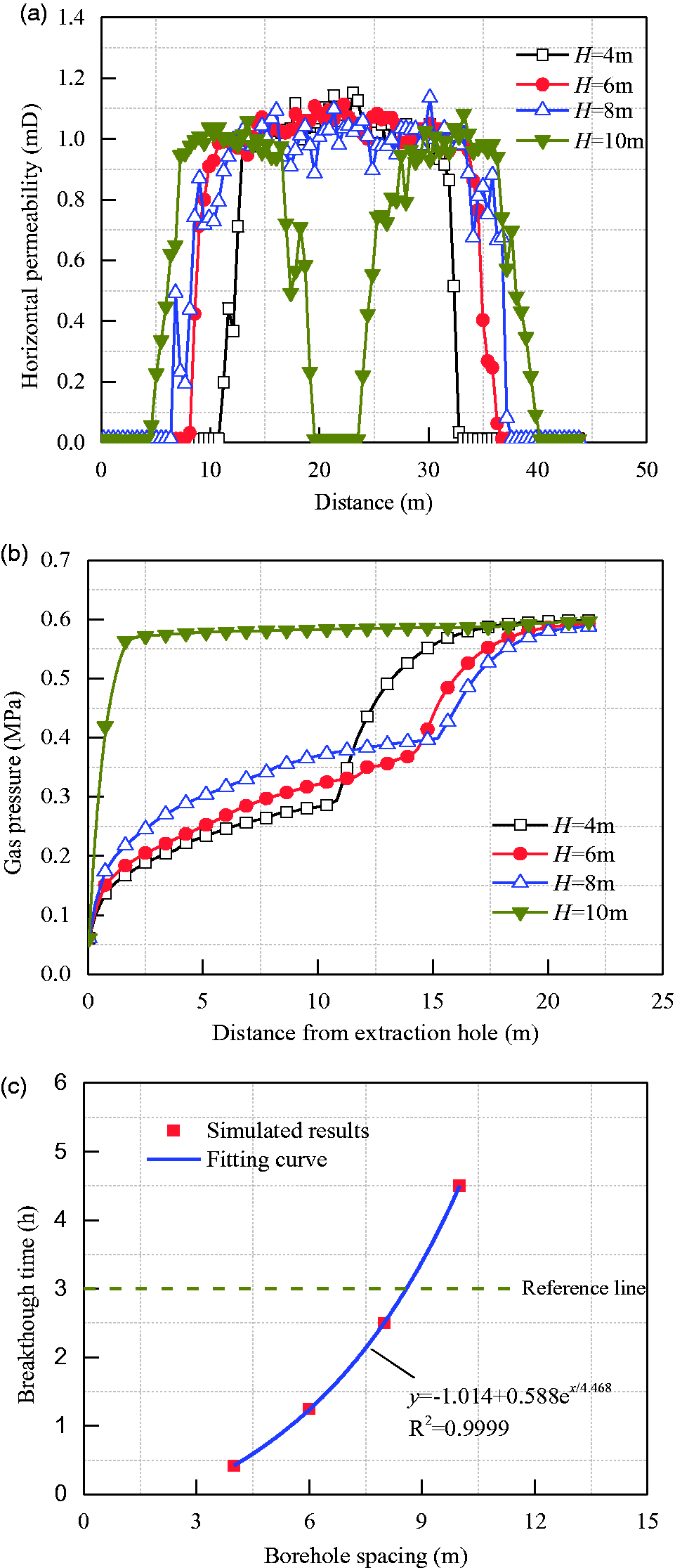
Parameter evolutions with different borehole spacing.
Fluid injecting pressure
In terms of coal seam with low permeability, the natural fractures can hardly form fracture network. Therefore, hydraulic fracturing is needed to force fractures to expand and connect with each other. And a proper value of injecting pressure can avoid problems of difficult sealing and ineffective fracturing. Figure 13 presents the evolutions of horizontal permeability, gas pressure and breakthrough time with different fluid injecting pressure pin. It is found in Figure 13(a) that the rising area of permeability spreads with increasing of injecting pressure pin. When pin = 12, 16 MPa, the effective fracturing radius is 6.24 m and 7.12 m respectively, which is smaller than the borehole spacing. This indicates that fracturing induced damage zone could not break through at the drainage borehole. On the contrary, when pin = 20, 24 MPa, the effective fracturing radius is greater than borehole spacing and the damage zone could break through. The permeability around drainage borehole will increase rapidly. Figure 13(b) shows that higher injecting pressure will result greater gas pressure drop. When pin = 12, 16, 20, and 24 MPa, the gas pressure of td = 60 d at the position of 8 m from drainage borehole is 0.583, 0.567, 0.346, and 0.328 MPa, respectively. The breakthrough time decreases with the increasing of injecting pressure, and has an exponential function with injecting pressure (Figure 13(c)). Under the geological condition of panel 15108, the damage zone can be connected at the drainage borehole within 3 h if the injecting pressure is larger than 17.61 MPa.
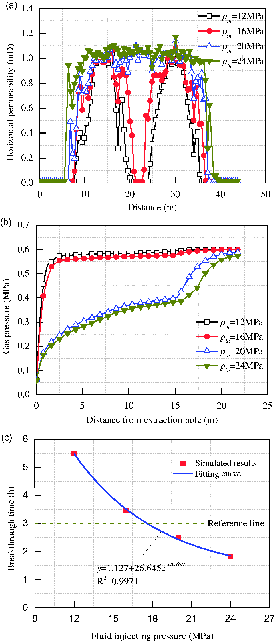
Parameter evolutions with different fluid injecting pressure.
Vertical stress
Generally speaking, the permeability is low when the coal seam is confronted with high compressive geostress. The injecting pressure should overcome the geostress to further develop fractures in coal seam. Figure 14 shows the evolutions of horizontal permeability, gas pressure, and breakthrough time with different vertical stress σv. It is observed that the effective fracturing radius of vertical stress σv = 18, 20 MPa is 6.68 m and 5.36 m, respectively when fractured time tf is 2.5 h. In this case, the effective fracturing radius is smaller than borehole spacing that the damage zone near drainage borehole could not be connected and the permeability is close to the initial value. When the vertical stress σv = 14, 16 MPa, the permeability near drainage borehole increases rapidly due the breakthrough of damage zone. As shown in Figure 14(b), after 60 days’ drainage, gas pressure on line O–B at the position of 8 m from drainage borehole is 0.320, 0.346, 0.572, and 0.581 MPa corresponding to σv = 14, 16, 18, 20 MPa. The exponential increase relationship between breakthrough time and vertical stress is revealed in Figure 14(c). In this term, the damage zone can break through within 3 h fracturing when the vertical stress is smaller than 16.96 MPa.
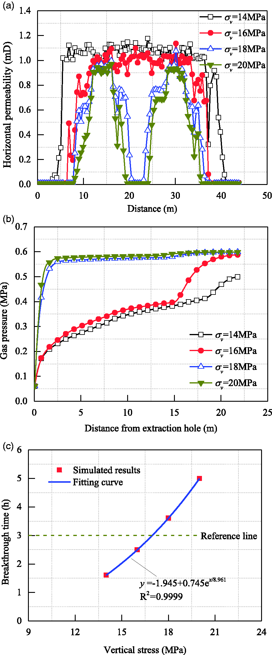
Parameter evolutions with different vertical stress.
Elastic modulus of coal seam
Elastic modulus reflects the difficulty of coal deformation and the ability of coal to bear and resist failure. As shown in Figure 15(a), when the elastic modulus of coal seam E is 4.81 GPa, the effective fracturing radius is 6.35 m and permeability near drainage borehole is close to initial value. In contrast, when E = 1.81, 2.81, 3.81 GPa, the damage zone is connected and the effective fracturing radius reaches to the borehole spacing, leading to rapid increase of permeability near drainage borehole. It is found in Figure 15(b), when E = 1.81, 2.81, 3.81, 4.81 GPa, the gas pressure at the position of 8 m from drainage borehole with td = 60 d is 0.332, 0.346, 0.41, and 0.581 MPa, respectively. In other words, the greater the elastic modulus of coal seams, the larger the capacity of coal mass to resist damage, and the more difficult the fracturing will be. As displayed in Figure 15(c), the breakthrough time linearly increases with the elastic modulus of coal seam. It can be calculated that the breakthrough time is 3 h when the elastic modulus is 4.59 GPa.
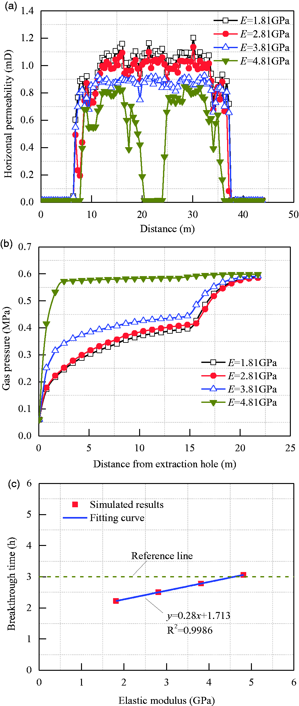
Parameter evolutions with different coal seam elastic modulus.
Conclusions
In this work, a fully coupled HSD model with two-phase flow was proposed for simulating the whole processes of hydraulic fracturing enhancing underground gas drainage. This model was verified and used to quantitatively analyze several influence factors. The following conclusions can be drawn:
The proposed HSD coupled model includes coal deformation and damage, gas migration, and water transport governing equations, and coupling terms of porosity and permeability. The overall trend and values of gas flux measured in field fits well with the simulated result which validates the accuracy of this model. This model can be used to simulate the whole process of hydraulic fracturing enhancing underground gas drainage. Due to the limitation of finite element method, it is difficult to display the propagation of the crack obviously. The expansion of coal damage was used to indirectly reflect the fracture development. The permeability in damage zone around drainage borehole increases rapidly, which can promote gas to migrate into drainage borehole. The damage zone breakthrough at drainage borehole is the insurance of hydraulic fracturing enhancing underground gas drainage. The breakthrough time of damage zone increases linearly with elastic modulus of coal seam, increases exponentially with vertical stress and borehole spacing, and decreases exponentially with injecting pressure. In Mabao coal mine, the breakthrough time can be shorter than 3 h only when the borehole spacing is smaller than 8.58 m, or the injecting pressure is larger than 17.61 MPa.
Footnotes
Acknowledgments
We would like to thank all editors and anonymous reviewers for their comments and suggestions.
Declaration of conflicting interests
The author(s) declared no potential conflicts of interest with respect to the research, authorship, and/or publication of this article.
Funding
The author(s) disclosed receipt of the following financial support for the research, authorship, and/or publication of this article: This research was financially supported by the State Key Research Development Program of China (Grant No. 2016YFC0801407–2), the National Natural Science Foundation of China (Grant Nos. 51674132 and 51604139), the Open Projects of State Key Laboratory of Coal Resources and Safe Mining, CUMT (Grant No. SKLCRSM15KF04), the Research Fund of State and Local Joint Engineering Laboratory for Gas Drainage & Ground Control of Deep Mines (Grant No. G201602), the Research Fund of State Key Laboratory Cultivation Base for Gas Geology and Gas Control (Henan Polytechnic University) (Grant No. WS2018B05), the Basic Research Project of Key Laboratory of Liaoning Provincial Education Department (Grant No. LJZS004), and the Natural Science Foundation of Liaoning Province (Grant No. 2015020614).