
Abstract
Fracture-hosted methane hydrate deposits exist at many sites worldwide. The growth behavior of CH4 hydrate in fractured media was simulated by TOUGH + HYDRATE (T + H) code. The effects of fracture size, initial condition, and salinity on the growth behavior of hydrate in fractures were investigated. In general, the hydrate layer grew from the two ends and gradually covered on the surface of the fracture. With the formation of hydrate in fractures, the temperature increased sharply since the hydrate acted as a thermal insulation layer. In longer fractures, fast growth of hydrate at the ends of the fracture led to the formation of hydrate plugs with high saturation (called as stopper). In narrower fractures, hydrate dissociation occurred in the middle of the fracture during hydrate growing in the whole fracture due to the cutoff of gas supply by the stopper at the ends. At a low initial subcooling, hydrate formed both on the surface and in the micropores of the media, which was different from that at higher subcooling. In salt solution, the formation of hydrate stopper was inhibited by the salt-removing effect of hydrate formation and the growth of hydrate was more sustainable.
Introduction
Natural gas hydrates (NGHs) are ice-like solids composed of water and hydrocarbon molecules, which exist abundantly in the permafrost and offshore environments. NGHs have attracted increasing attentions from both industry and academia as a possible source of a supply of future energy as they own high gravimetric/volumetric energy storage density and enormous quantities. Each volume of hydrate can contain as much as 164 volumes of gas at standard temperature and pressure (Koh et al., 2012). They are estimated to contain more than half of world’s total organic carbon and twice as much as all other fossil fuels. Hence, NGHs are regarded as a potential unconventional energy resource.
A number of drilling expeditions have been undertaken in various parts of the world to gain a better understanding of the physical and chemical processes associated with methane hydrate accumulations (Tréhu et al., 2006). Fractures in sediments are the best tunnel for free gas to migrate and therefore they are the best location to form massive hydrate (Chen et al., 2017; Daigle and Dugan, 2010a, 2010b). Fracture-hosted methane hydrate deposits exist at many sites worldwide, such as Qilian Mountain of China (Lu et al., 2011), Hydrate Ridge offshore Oregon, the northern Gulf of Mexico (Lee and Collett, 2012), the Krishna-Godavari Basin offshore India (Lee and Collett, 2009), and Ulleung Basin (Lee and Collett, 2013; Riedel et al., 2012), East Sea of Korea. These sites often have hydrate present as vein and fracture fill, as well as disseminated through the pore space (Tréhu et al., 2006). The fracture-hosted hydrate always locates at depths of several hundred meters below the seafloor or below the permafrost regions (Daigle and Dugan, 2010b). Particular attention has been paid to the geomechanical aspects of methane hydrate formation in preexisting fracture networks or creation of new fracture networks caused by hydrate formation (Lee and Collett, 2009; Nimblett and Ruppel, 2003). However, detailed studies on hydrate formation in fractures in sediments have been limited. So far, the researches about fracture-hosted hydrates are mainly focused on the physical properties of hydrated formations and hydrate distributions by analyzing the data of seismicity and logging-while-drilling logs (Riedel et al., 2012; Sriram et al., 2013; Wang et al., 2013). Previous studies have shown that hydrate formation can lead to cementing of coarse-grained sediment, which has been suggested to lead to fractures in the sediment. Daigle and Dugan (2010b) studied the origin and evolution of fracture-hosted methane hydrate deposits and assessed fracture formation at well-studied hydrate provinces with a coupled fluid flow-hydrate formation model. Chen et al. (2017) observed methane hydrate growth and evolution in a fracture of coarse sands using a one-dimensional visual simulator. Our group (Sun et al., 2015) experimentally studied the formation and equilibrium conditions of fracture-filled methane hydrates in core stone. It was found that the massive and layer hydrates are the main occurrences in fractures. The fracture scale did not have a significant influence on the thermodynamic equilibrium of the gas hydrates.
Numerical modeling is an important tool to study the formation and accumulation process of gas hydrate in marine sediments (Cao and Chen, 2011; He et al., 2011; Sato 2015; Suetnova 2007; Uddin et al., 2008). Over the last decades, great achievements have been made in the numerical modeling. In this work, we performed numerical simulation on the formation of methane hydrate in the fractures of the core through TOUGH + HYDRATE (T + H) code (Moridis et al., 2008). The influences of fracture size, initial subcooling conditions, and salinity on gas hydrate growth and distribution in fractures were analyzed by tracking the evolution of hydrate saturation, pressure and temperature during hydrate formation, and examining the conditions that led to hydrate formation by coupling fluid flow and hydrate equilibrium properties. We related hydrate occurrence and distribution behaviors in fractures to fracture physical properties and environmental conditions. Our results would help to determine what factors favor hydrate accumulation in fractures over hydrate accumulation in pore space, and what controls the growth and distribution of gas hydrate in fractured system. The understanding of massive hydrate accumulation in fractures should be important for the exploration and exploitation of NGHs.
Numerical description
Numerical simulator
The numerical simulations were conducted using the TOUGH + HYDRATE v1.2 simulator (Moridis et al., 2012), which was a code for the simulation of the behavior of hydrate-bearing geologic systems and represented the second update of the code since its first release. By solving the coupled equations of mass and heat balance, TOUGH + HYDRATE can model the nonisothermal gas release, phase behavior, and flow of fluids and heat under conditions typical of common natural methane hydrate deposits (i.e. in the permafrost and in deep ocean sediments) in complex geological media at any scale (from laboratory to reservoir) at which Darcy’s law is valid. In this code, the impact of the movement and the volume expansion of the sediments are neglected.
Geometry, domain discretization, and system properties
The physical system was described as a 2D rectangular coordinate system to simulate the morphology and growth behavior of methane hydrate in fractured media at laboratory scale. Figure 1 illustrates the numerical representation of the physical system. A transfixion fracture along the Y-direction was set at the center of the model. The gas boundary was set around the model.
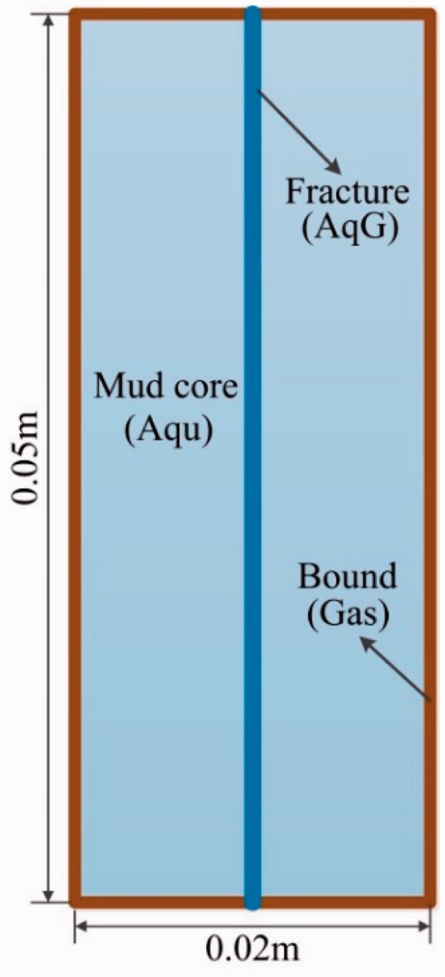
Schematic of the numerical model.
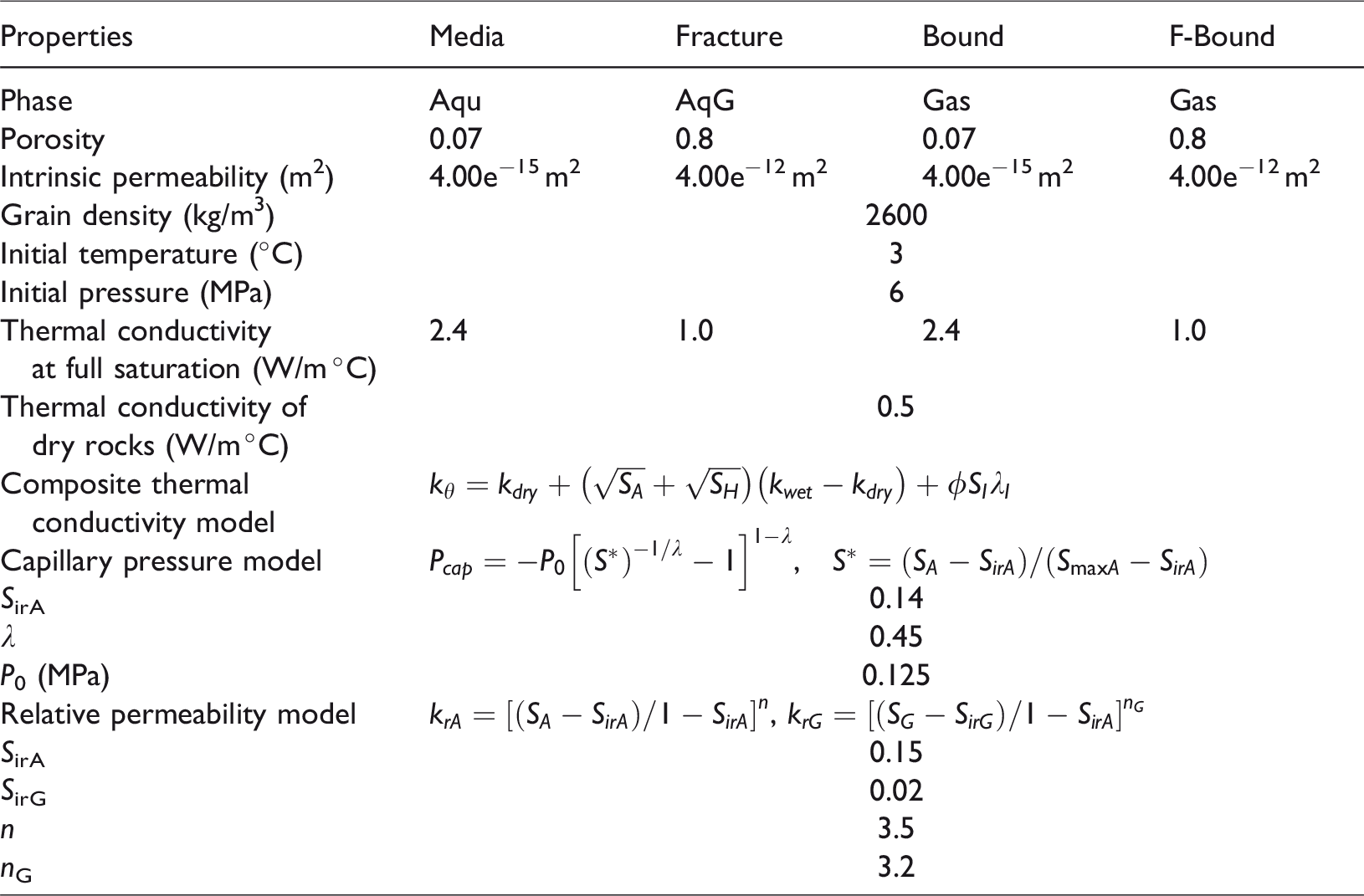
The rectilinear grid model was discretized into 26 cells in the X-direction and 54 layers in the Y-direction. The refinement of grids was applied on and around the fracture. The surrounded elements of the model were set as the inactive boundaries, through which heat and mass could be transferred to the simulation domain. The physical properties and initial conditions of the model based on Sun et al. (2014) are shown in Table 1.
Parameters for simulation.
The growth behaviors of methane hydrate in fractures were investigated by means of numerical simulations with respect to the formation of hydrate in fractures in experiments (Sun et al., 2015). As mentioned, the code we employed is TOUGH + HYDRATE, which is developed by the Lawrence Berkeley National Laboratory. By using an equilibrium and kinetic hydrate formation and dissociation model, the code can simulate the nonisothermal gas release, phase behavior, as well as fluid and heat flow under conditions typical for natural CH4 hydrate deposits in complex geological media. The formation, morphology, and stable state of hydrate are relevant with the formation physical properties (porosity, permeability) and the local environmental conditions (fluid, pressure, temperature, methane supply) (Wang et al., 2014). We conducted eight simulations on the effects of fracture properties of length and width, initial conditions of subcooling, and salinity on hydrate formation, as were listed in Table 2.
Simulation conditions and hydrate growth modes.
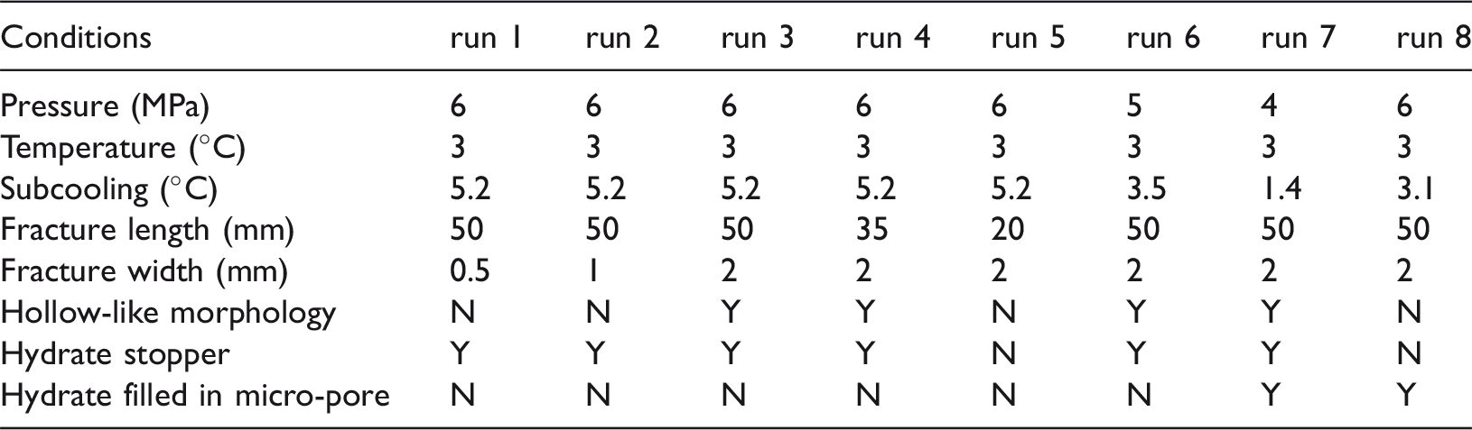
Y indicates the phenomenon exists; N indicates no such phenomenon.
Results and discussion
In our previous study, hydrate was formed in fractured stone in experiments. For comparison, the morphology of the hydrate formed in the fractured media obtained is shown in Figure 2 (Sun et al., 2015). It can be seen from Figure 2(a) that the top of the mudstone core is covered with a layer of hydrate. The fracture is seemed to be sealed by hydrate, which is also observed in the numerical simulations. Figure 2(b) shows the morphology of hydrate in the fracture after the mudstone core was split. It can be observed that hydrate distributed uniformly on the inner surface of the fracture. The phenomenon should be attributed to certain features of the fractured core. First, as the clay minerals in mudstone have a strong ability of adsorbing water, a uniform water layer was distributed inside the fracture. Second, after the injection of methane into the system, hydrate preferentially formed at the surface of the core and inner surface of the fracture where water/gas interface existed. Besides, the growth mode of hydrate layer along the inner surface of the fracture may also be related to the temperature distribution feature observed in numerical simulation.
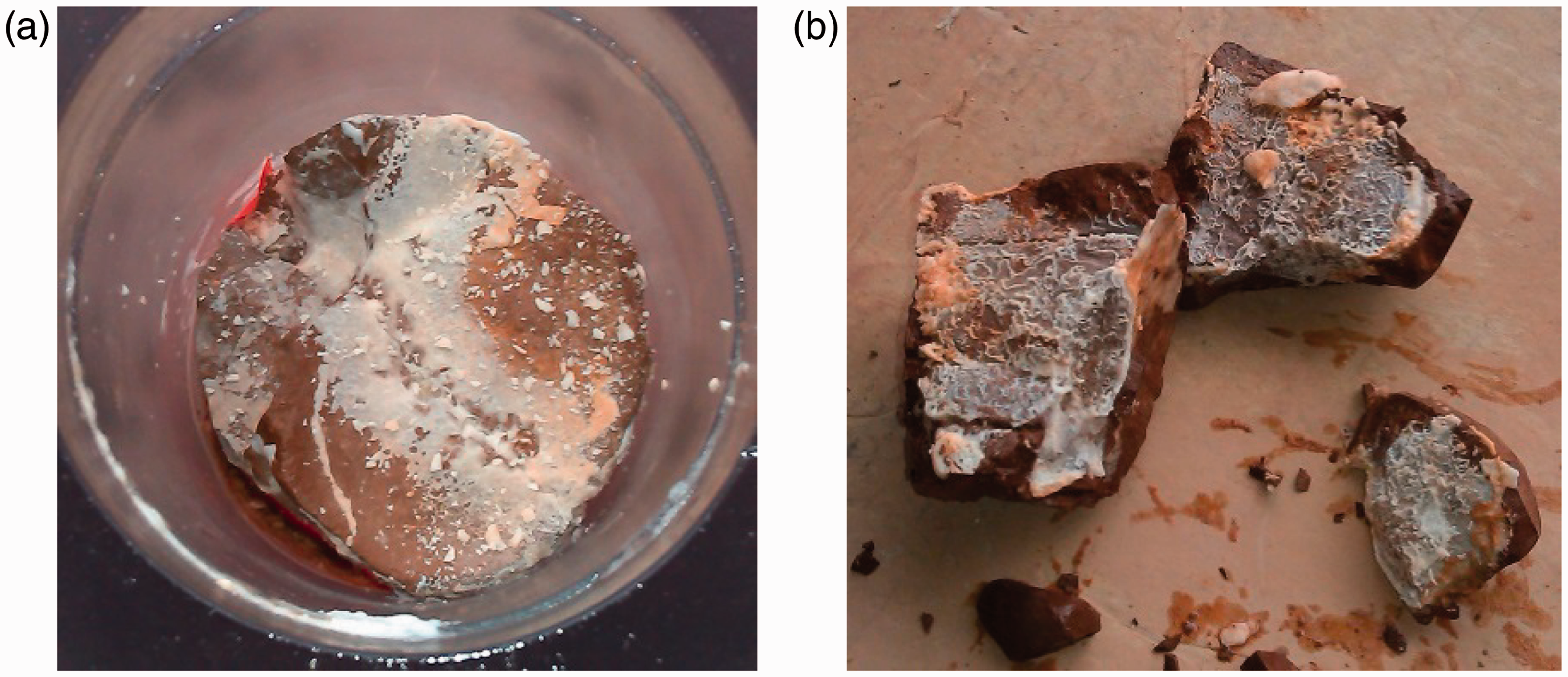
The morphology of fracture-filled methane hydrate (Sun et al., 2015).
General growth mode of hydrate in fractures
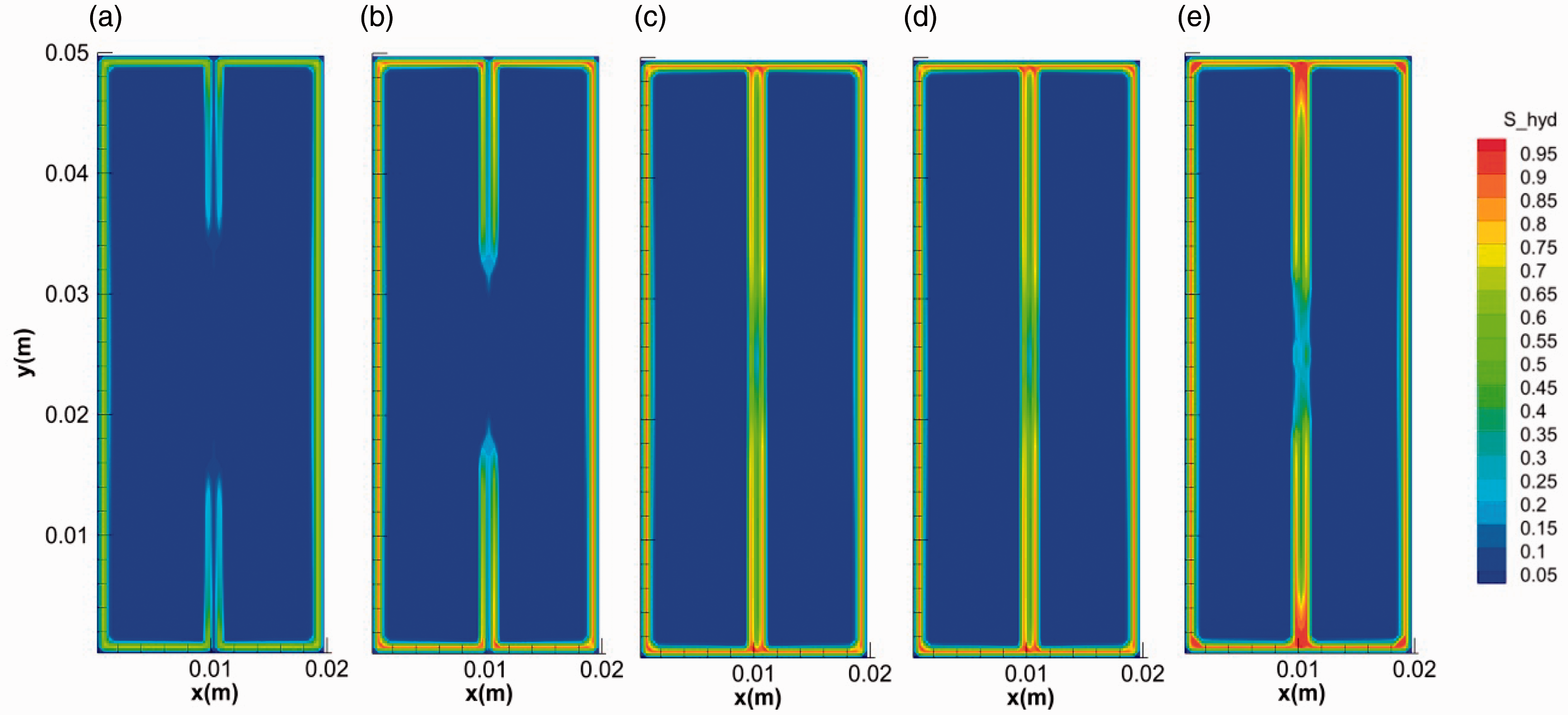
We take run 2 case to show the general mode of hydrate growth in fractured media. Figures 3 and 4 show the distribution and evolution of the hydrate saturation and gas saturation in the system during hydrate formation, respectively. In the initial stage, on one hand, the surface of core is covered by a thin hydrate layer with high saturation. The gas around cannot penetrate through this layer for further hydrate formation in the micropores in the core media. On the other hand, hydrate grows from the two ends of the fracture to the middle and hydrate layers gradually cover on the surface of the fracture, which is in accordance with the experimental results in Figure 2(b). Hydrate layer covers on the inner surface of the fracture. The evolution of gas saturation keeps in step with that of hydrate saturation. The gas diffuses along the fracture as shown in Figure 4(a) and (b), supporting the growth of hydrate in fracture. The saturation of hydrate formed on the inner surface of fracture is higher than that in the center of the facture. Hydrate with hollow-like morphology distributes in the fractures (Figure 3). The specific growth mode of hydrate can be attributed to the temperature distribution over the fractured media. As the formation of hydrate is an intensively exothermic reaction (Yang et al., 2014), the heat from hydrate formation will accumulate in the center with the limitation of fracture. After hydrate layer covering on the inner surface of fracture, the diffusion of heat became more difficult due to the much lower thermal conductivity of hydrate (0.3 W/(m °C)) (Huang and Fan, 2005; Yang et al., 2015; Zhao et al., 2015) than that of the core media (2.4 W/(m °C)). The hydrate layer on the inner surface of fracture can be regarded as an insulation impeding the heat transfer. It can be seen from Figure 5 that the temperature in the center of the fracture is the highest. The sharp increase of temperature in the fracture can stop the growth of hydrate and even dissociate it into water and gas again.
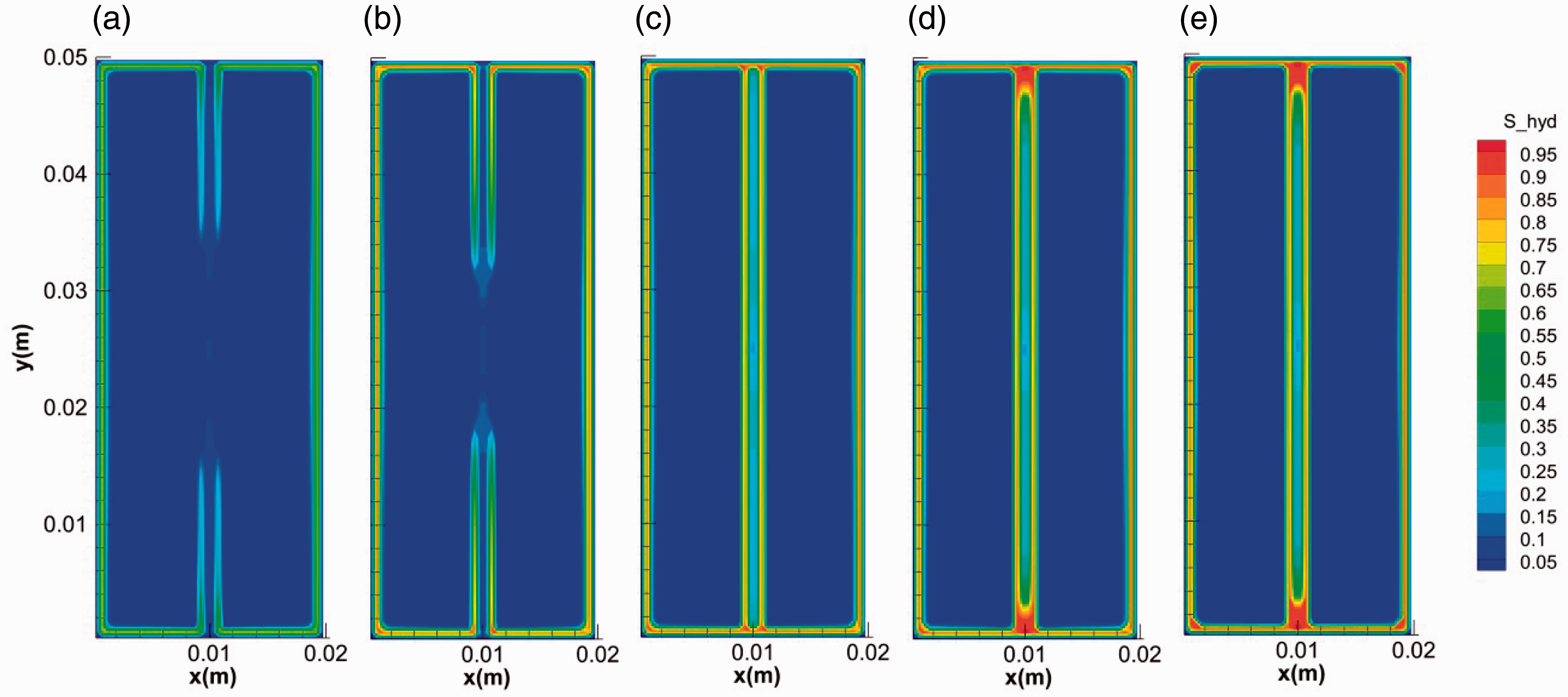
The evolution of the hydrate saturation during hydrate formation in fractures. (a) 0.1 s, (b) 1 s, (c) 10 s, (d) 100 s and (e) 400 s.
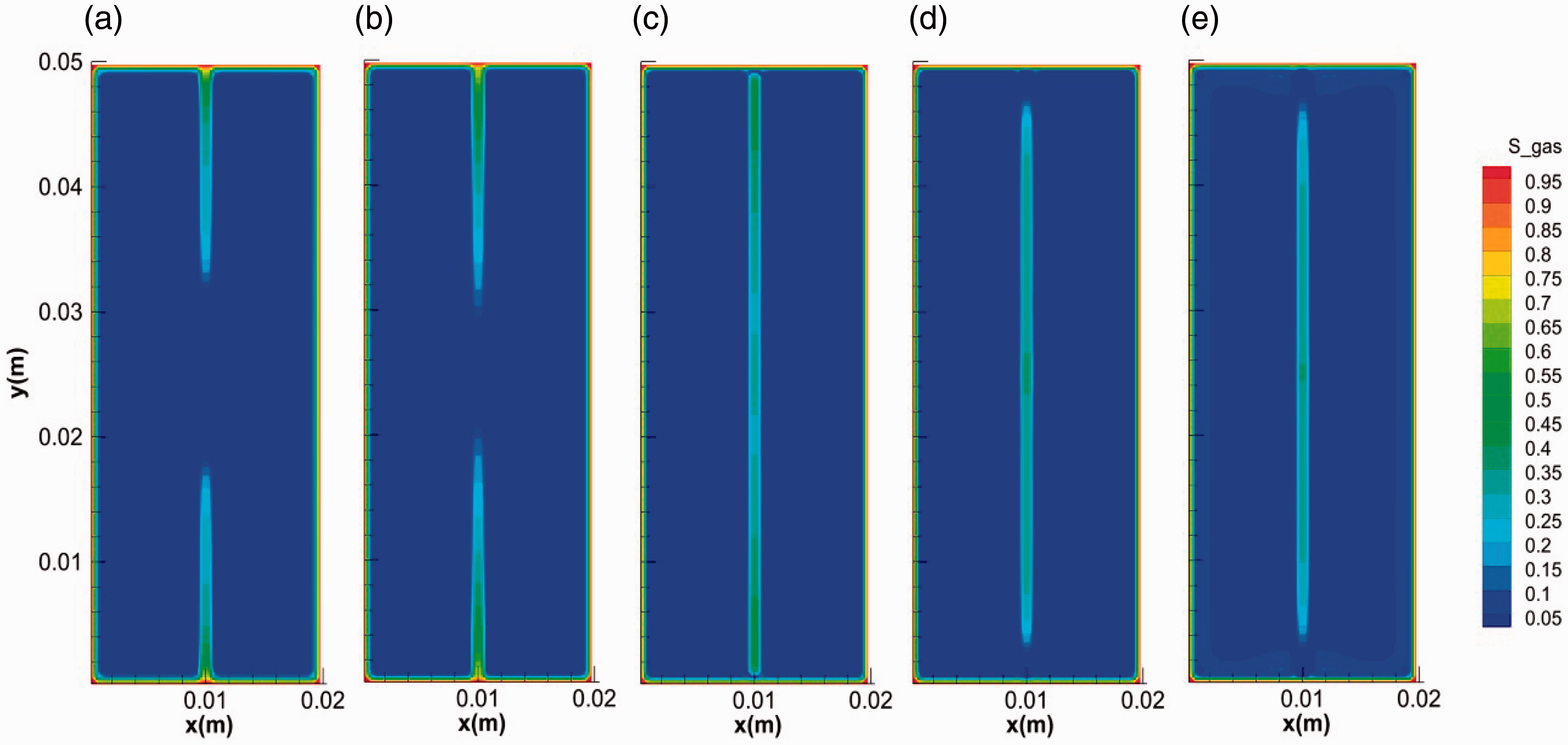
The evolution of the gas saturation during hydrate formation in fractures. (a) 0.1 s, (b) 1 s, (c) 10 s, (d) 100 s and (e) 400 s.
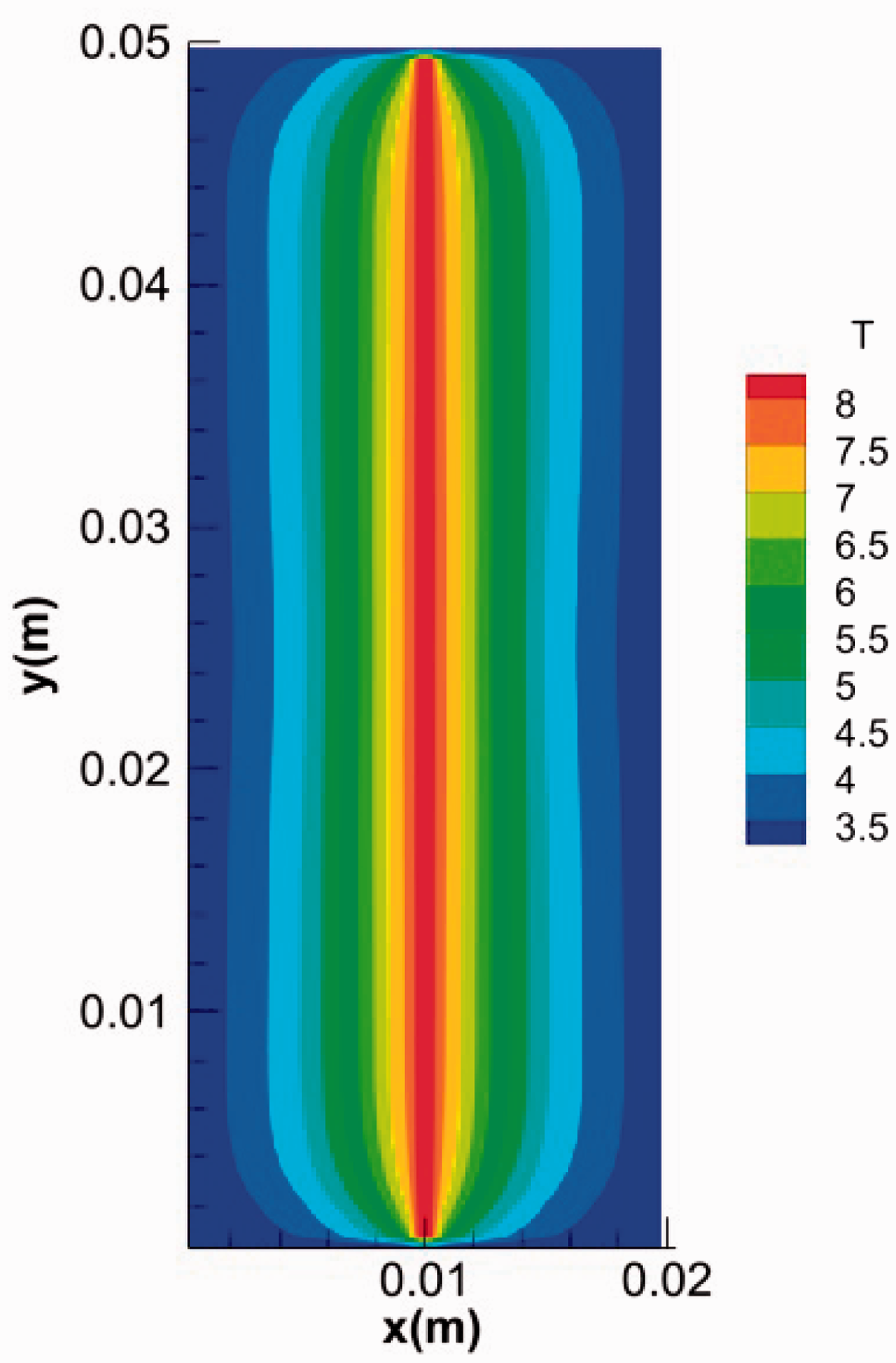
The temperature distribution of model at t = 10 s.
Previous studies show that hydrate prefers to form with rich methane supply and advantageous conditions (lower temperatures and higher pressures) (Chen et al., 2014, 2017). The ends of fracture are the proper formation positions close to the low-temperature gas boundary. After the temperature increased in the center of fracture with the formation of hydrate, hydrate can quickly accumulate at the ends of fracture and form plugs with high saturation (called as stopper in this work), as is shown in Figure 3(c) to (e), which is similar to the hydrate seal in Figure 2(a) and cut off the mass transfer between the fracture and the gas boundary for further hydrate formation (Takahashi et al., 2012). Then with the consumption of the gas sealed in the fracture for a slower hydrate formation, the pressure and temperature in the fracture decreased quickly to hydrate equilibrium values (Figure 6).
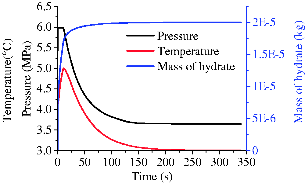
The evolution of pressure, temperature, and mass of hydrate during the formation.
Effect of fracture length on hydrate growth behavior
To investigate the influence of fracture length on hydrate growth behavior, the simulations with different fracture lengths were conducted (runs 3, 4, and 5). Figure 7 shows the final distribution of hydrate in fractures with different lengths (20, 35, and 50 mm). It was easy to distinguish the phenomenon in fracture with length of 20 mm from that of the other two by the absence of the stoppers at the ends. The temperature at the ends of fractures changing with the time was extracted and plotted in Figure 8. It shows the temperatures at the initial stage were all higher than 8°C. For fractures with shorter length, the duration of high temperature at the ends and in the middle was longer. The evolution of water saturation in the fractures is shown in Figure 9. It indicated that the consumption of water at the ends was associated with the temperature. Longer duration of temperature means more hydrate formation and less water remained (Yang et al., 2014). If most of the water at the ends were consumed for hydrate formation before the decline of temperatures, the stopper at ends would not have formed (see Figures 7(a) and 9(a)). As a result, the pressure in shorter fracture of 20 mm kept unchanged during hydrate formation while the pressure in longer fractures of 35 and 50 mm decreased obviously with the time (see Figure 10), which may be the reason that hydrate filled completely (not hollow morphology) in the shorter fracture.
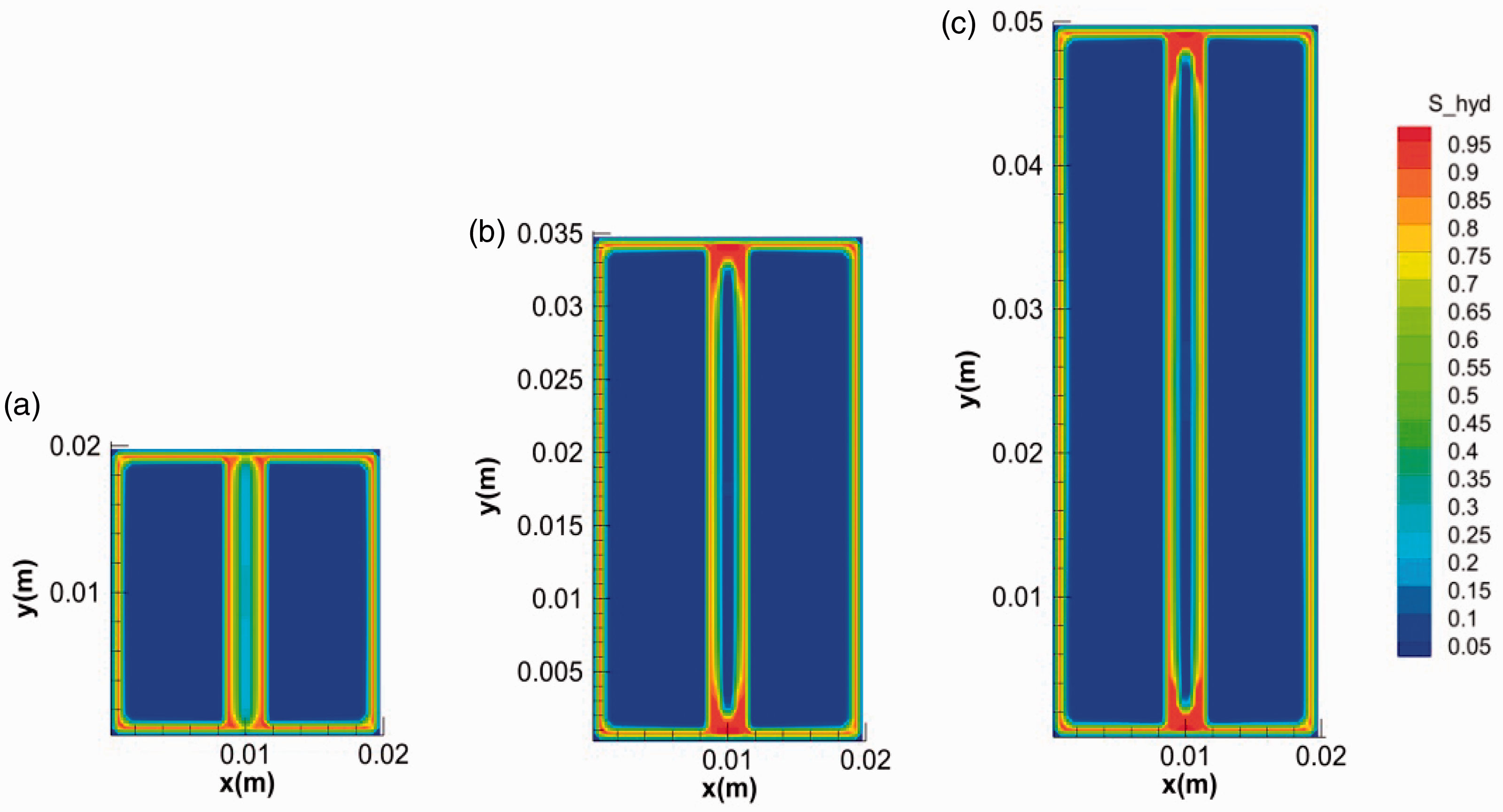
The final morphology of hydrates in fractures with different lengths: (a) 0.02 m, (b) 0.035 m and (c) 0.05 m.
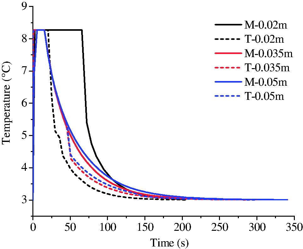
The evolution of temperatures at the top (T) and in the middle (M) of the fractures with different lengths.
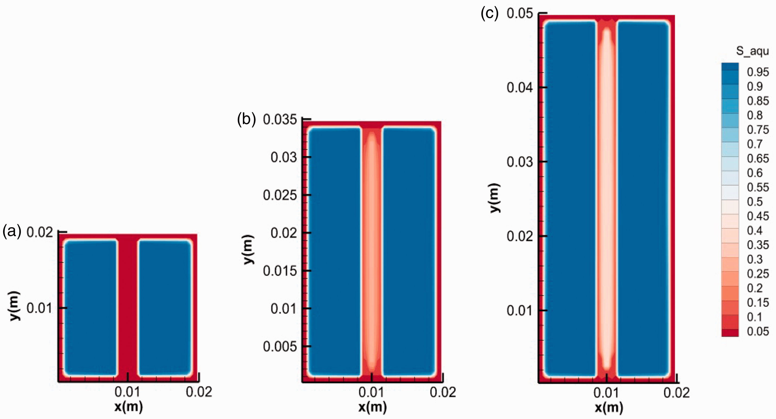
The final water distribution in fractures with different lengths: (a) 0.02 m, (b) 0.035 m and (c) 0.05 m.
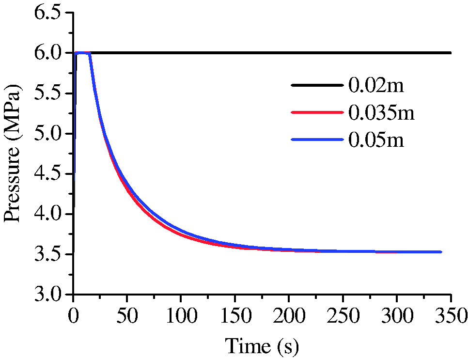
The evolution of the pressures in fractures with different length.
Effect of fracture width on hydrate growth behavior
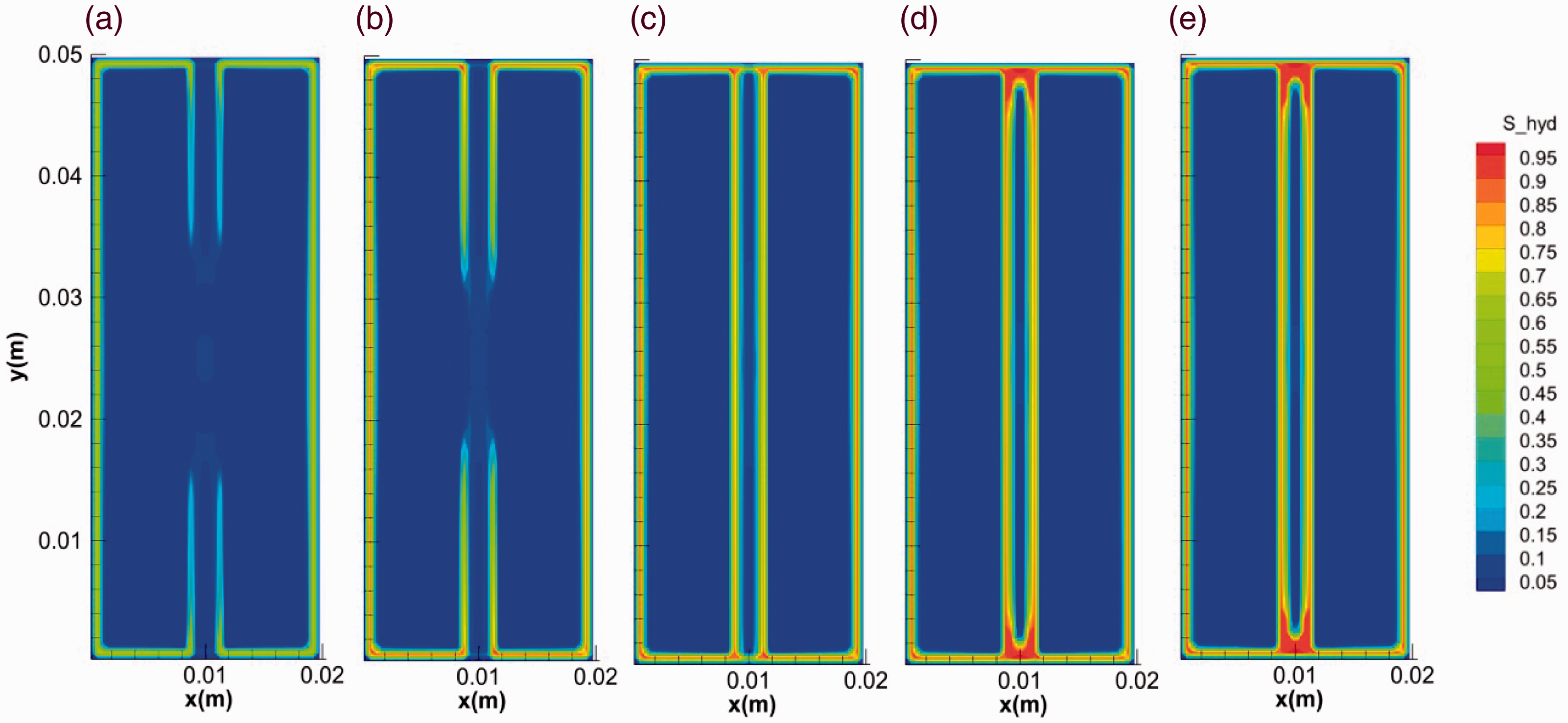
Besides the fracture length, the width also affects the hydrate morphology. Figures 11 and 12 show the evolution of hydrate saturation with the time in fractures with widths of 0.5 and 2 mm, respectively (runs 1 and 3). It can be seen that that the overall hydrate saturations in fracture increase with the decrease of fracture width. The hollow-like morphology is more obvious in the wider fracture. In addition, it can be observed that the saturation of hydrate in the middle of fracture with width of 0.5 mm decreased in the time range of 10–155 s, indicating the unusual dissociation of hydrate in the whole formation process, see Figure 11(c) to (e). The phenomenon can be caused by both the increase of temperature and the decrease of pressure in the fracture during hydrate formation (Sato, 2015). As is mentioned above, hydrate formation led to the rise of temperature in fractures and a couple of stoppers were likely to form at the two ends of the fractures. At a certain gas concentration, less gas amount was contained in a narrower fracture. When the stoppers formed during the formation of the hydrate layer, the pressure in narrower fracture (0.5 mm) dropped below the equilibrium value more easily due to the gas consumption. As a result shown in Figure 11, the hydrate layer formed in the middle of the fracture dissociated into water and gas again.
The evolution of hydrate saturation in fractures during the formation (0.5 mm). (a) 0.1 s, (b) 1 s, (c) 10 s, (d) 100 s and (e) 400 s.
The evolution of hydrate saturation in fractures during the formation (2 mm). (a) 0.1 s, (b) 1 s, (c) 10 s, (d) 100 s and (e) 400 s.
Effect of initial subcooling on hydrate growth behavior
Subcooling is regarded as an important driving force for hydrate formation (Li et al., 2013). The evolutions of hydrate mass and temperature for runs 3, 6, and 7 with the same size of fracture at different subcoolings are shown in Figure 13. It can be seen that hydrate grows faster and the increase of the temperature is more obvious at higher subcoolings. Figure 14 depicts the final morphologies of hydrate at different subcoolings. At a lower initial subcooling of 1.4 K, hydrate can form both in micropores of the core and on the surface of the fracture (Figure 14(a)). There may be a competitive relationship between the two modes of hydrate formation. Hydrate layer with high saturations may become a barrier for the diffusion of gas from the surface to the inner of the media (Taylor et al., 2007). When the growth of hydrate on the core surface was slower at lower subcoolings, there would be more time for the growth of hydrate into micropores of the core. In contrast, as can be seen at higher subcoolings of 3.5 and 5.2 K, only hydrate layer with high saturation covered on the surface of the fractures and cores (Figure 14(b) and (c)).
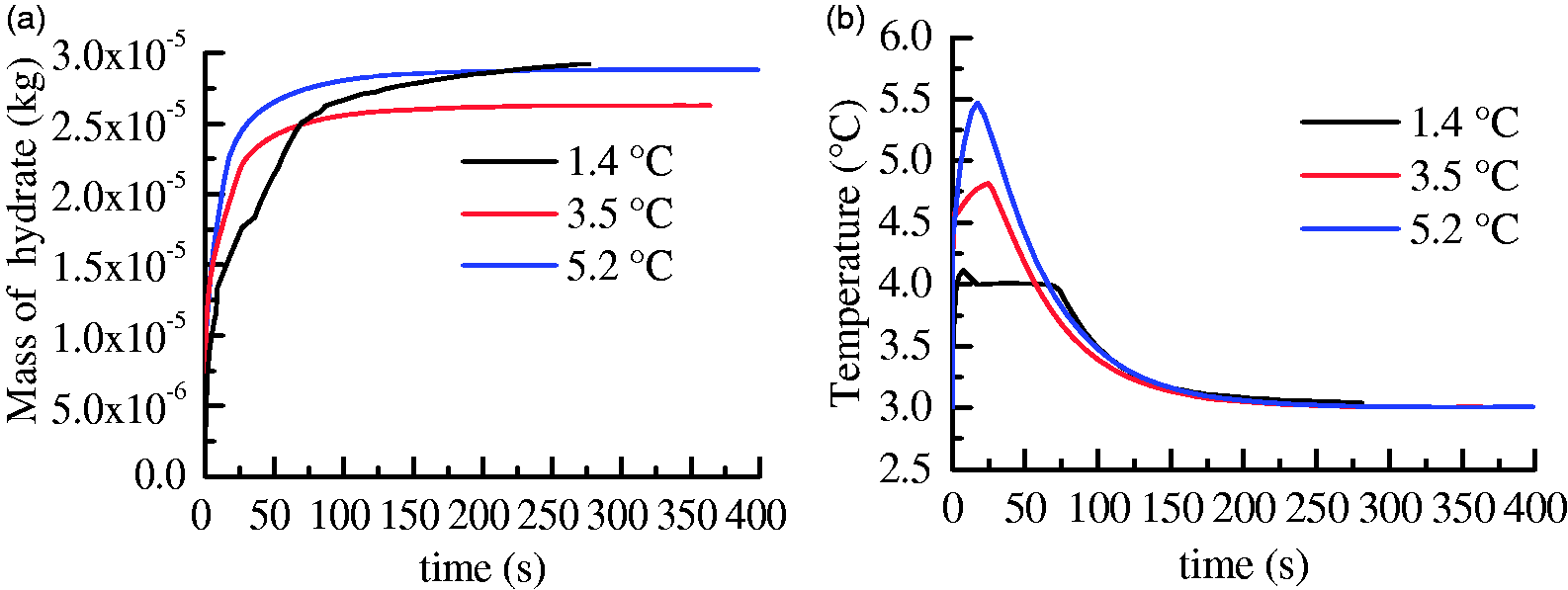
The evolutions of hydrate mass and temperature at different subcoolings. (a) Mass of hydrate and (b) temperature.
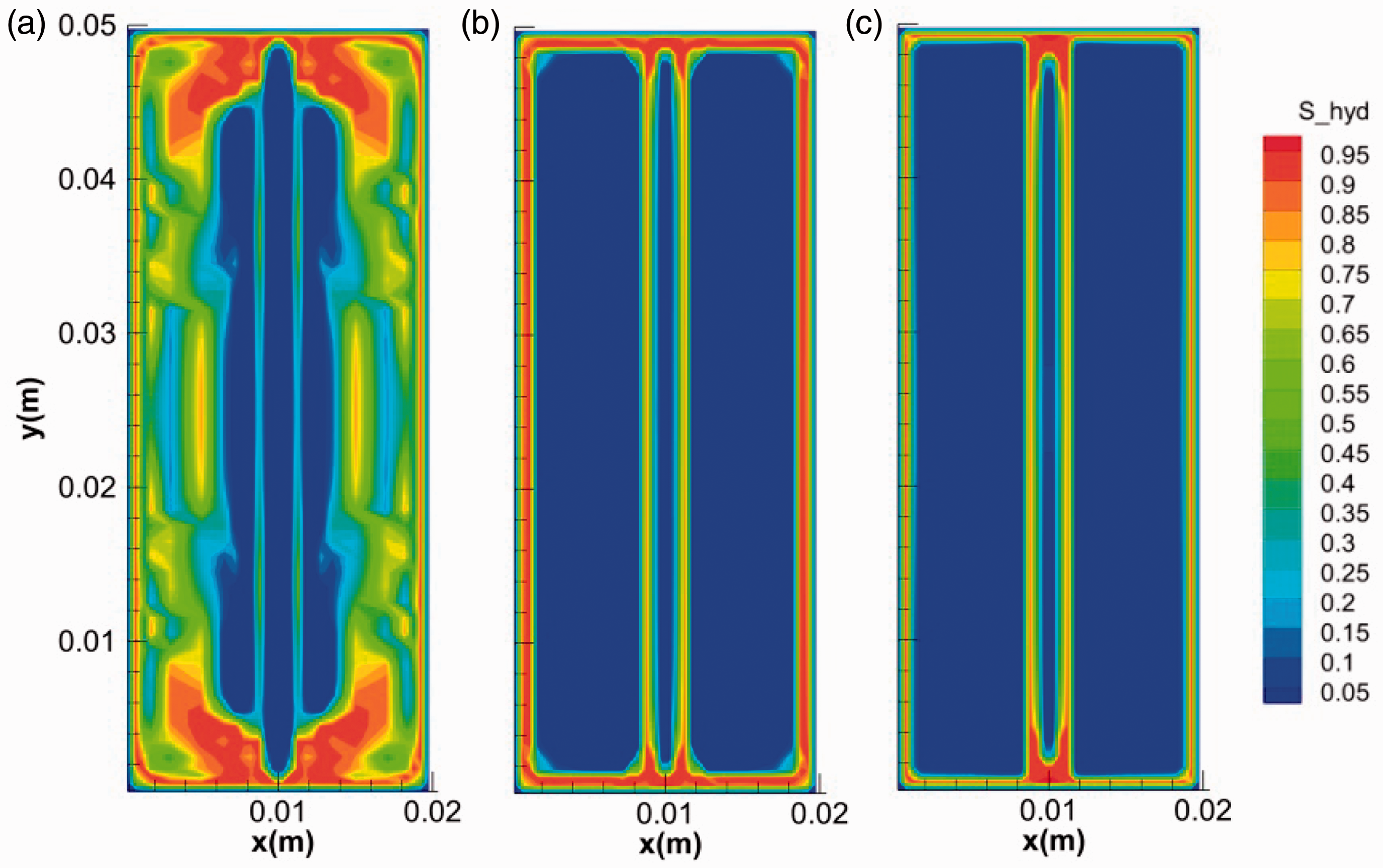
The final morphologies of hydrate at different subcoolings: (a) 1.4°C, (b) 3.5°C and (c) 5.2°C.
Effect of salinity on hydrate growth behavior
As fracture-filled hydrates are found in multiple regions of ocean, the electrolytes are strong thermodynamic inhibitors that change the fracture-hosting hydrate phase equilibrium (Mohammadi and Richon, 2009; Seo and Lee, 2003). Figure 15 shows the evolution of hydrate saturation in the solution of 3.5% NaCl. In the initial stage, the growth of hydrate was in the similar manner with that of no salt. Afterward, the growth of hydrate extended to the inner space of the media rather than strictly being limited in the fracture, as is shown in Figure 15(c) and (d). Finally, no hydrate stopper formed at the ends of the fracture and hydrate with high saturations distributes over the whole core. The increase of NaCl concentration was due to the salt-removing effect during hydrate formation (Liu et al., 2006). Since the gas boundary of the system was set as a water impermeable layer in the simulation, NaCl accumulated in the core space. As can be seen from Figure 16, the increase of salinity coincides with the increase of hydrate saturation, which may inhibit the formation of hydrate stopper at the ends of the fracture and hydrate layer with very high saturation on the surface of core. Therefore, in NaCl solution, the pressure in the fracture keeps unchanged and the temperature increases quickly and decreases slowly during hydrate formation (Figure 17), indicating a sustainable growth of hydrate both on the surface and in the micropores of the core media. As a result, the amount of hydrate formed in NaCl solution is larger than that in pure water (Figure 18).
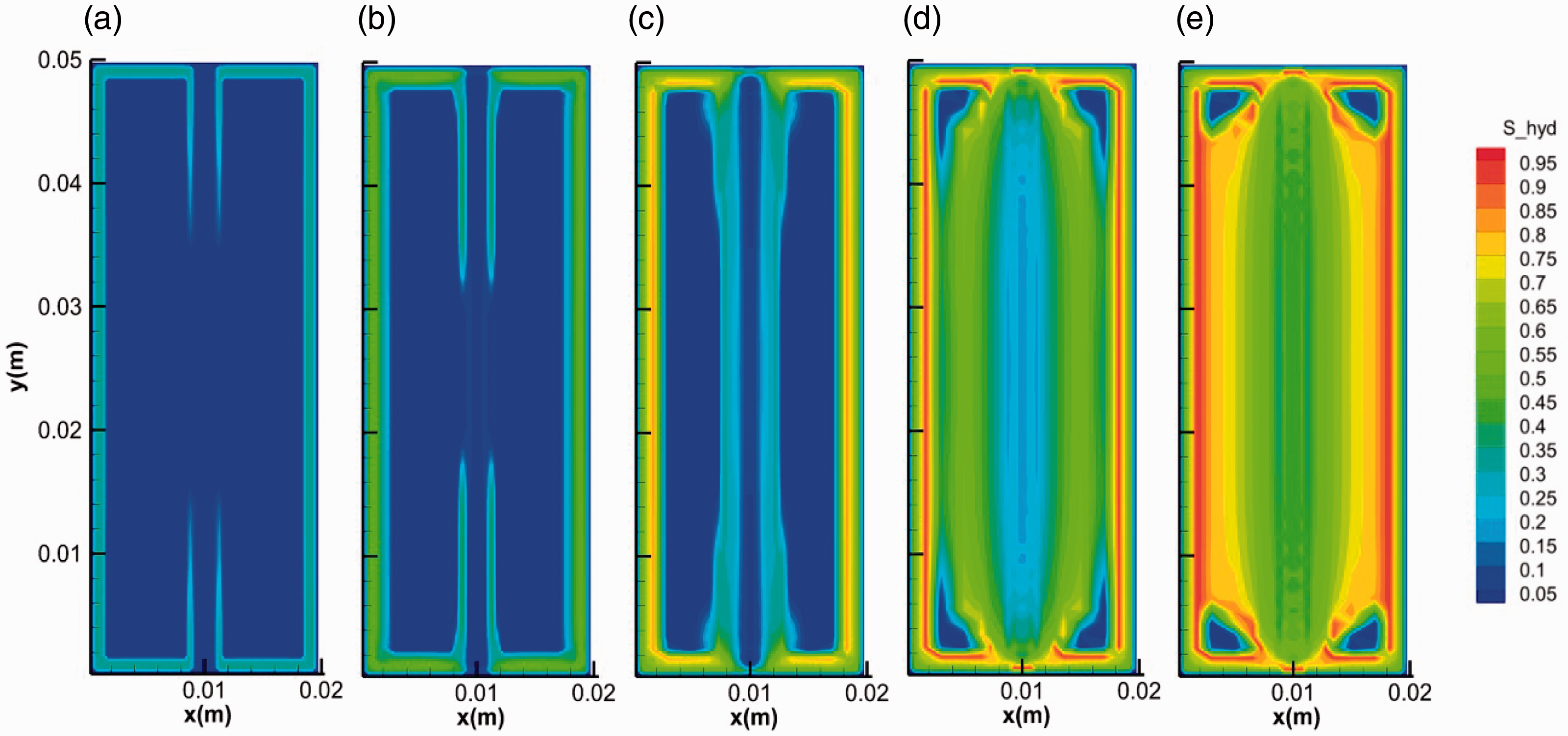
The evolution of hydrate saturation in 3.5% NaCl solution during the formation. (a) 0.1 s, (b) 1 s, (c) 10 s, (d) 100 s and (e) 600 s.
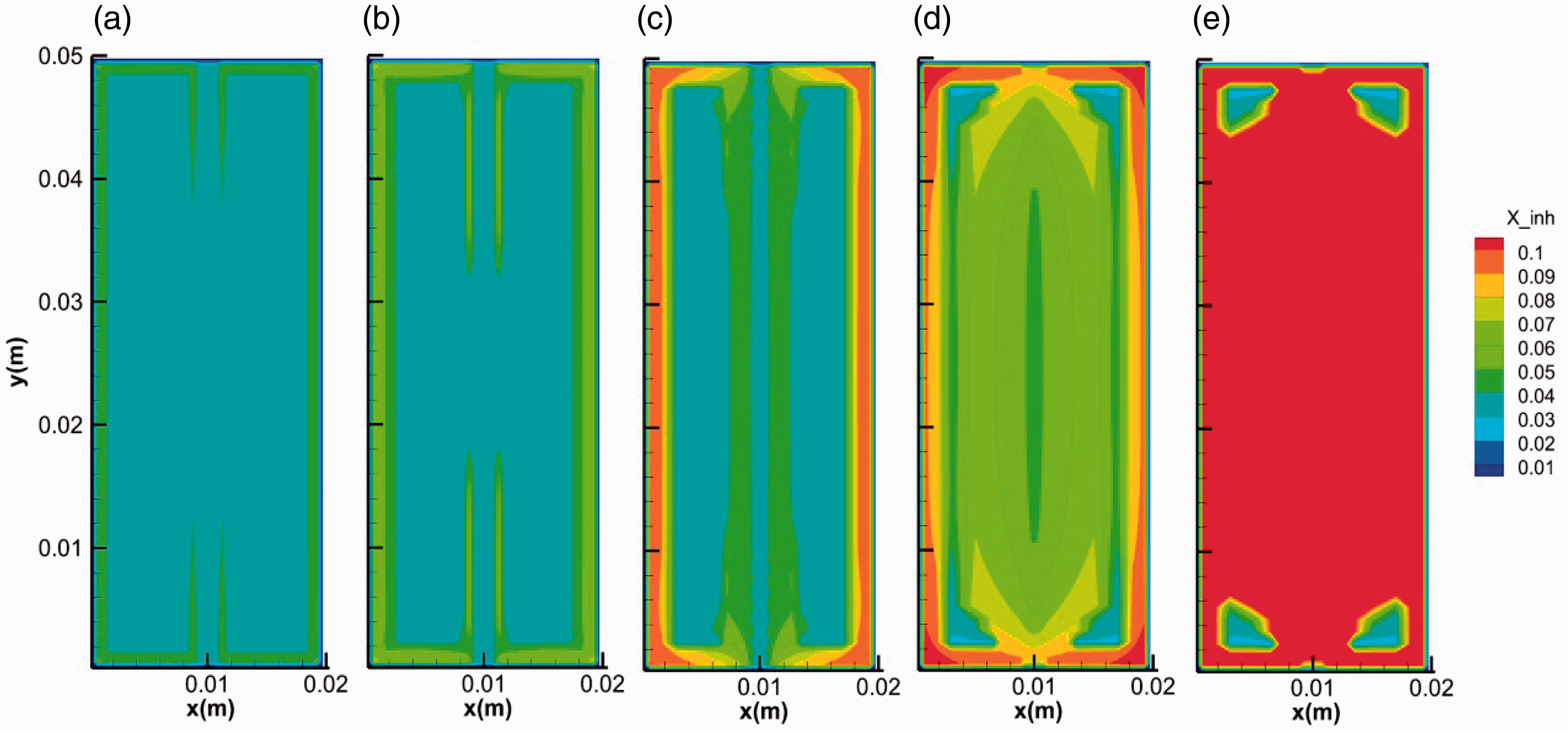
The evolution of salinity during the formation. (a) 0.1 s, (b) 1 s, (c) 10 s, (d) 100 s and (e) 600 s.
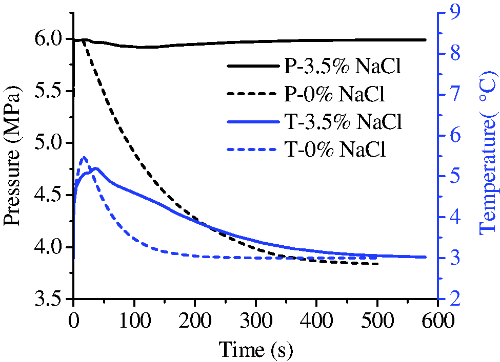
The evolution of pressure and temperature during the formation with and without NaCl.
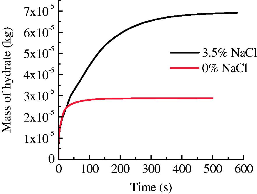
The evolution of hydrate mass during the formation with and without NaCl.
Conclusion
In this work, the growth behavior of hydrate in fractured media was investigated by using the TOUGH-HYDRATE code. The effects of the fracture size, initial conditions, and salinity on the hydrate growth behavior were studied. It was found that hydrate layer covered on the surface of fractures with different size, accompanied with the generation of a high temperature field in fractures. In longer fractures, hydrate stopper formed at the ends, which hindered the mass transfer from gas boundary to the fracture and could even cause the dissociation of hydrate during its formation in narrower fractures. There was a competitive relationship between the growth on the outside surface of core and in the pore space inside the core. Two factors such as subcooling and the salinity may change the competitive relationship. At low subcoolings or in NaCl solution, hydrate would grow not only in the fractures but also in the micropores of the core media.
Footnotes
Declaration of conflicting interests
The author(s) declared no potential conflicts of interest with respect to the research, authorship, and/or publication of this article.
Funding
The author(s) disclosed receipt of the following financial support for the research, authorship, and/or publication of this article: National Natural Science Foundation of China (Grant Nos. 51506073 and 51474112), the financial support received from the Key Laboratory of Unconventional Petroleum Geology, Oil and Gas Survey, China Geological Survey (DD20160226-01), and Key Lab of Drilling and Exploitation Technology in Complex Conditions (No. DET201601) are gratefully acknowledged.