
Abstract
Thermal stress deformation can cause serious casing damage and failure problems in thermal recovery wells. In this paper, mechanical performance experiments on rock and cement are carried out first, and then a finite element mechanical model of thermal recovery wellbore based on thermal-structure coupling is established. The thermal stress variation of wellbore based on thermal-structure coupling and its influence on casing residual stress are studied. The change rule of wellbore stress with a steam stimulation process is also analyzed using the model. The analysis results indicated that the rate of thermal expansion of each material was different in the wellbore. The casing and cement sheath were compressed, producing a large strain on the inner wall of the cement sheath. The local deformation of the wellbore rock acted on the casing under thermal stress, which caused casing deformation and failure. The relationship between the residual stress of the casing and the steam injection cycle was obtained through numerical simulation and was used to quantitatively evaluate and analyze the residual strength of the casing. The results of this study provide an important reference for wellbore mechanical evaluation and a theoretical basis for reasonable preventative measures for casing failure in thermal recovery wells.
Keywords
Introduction
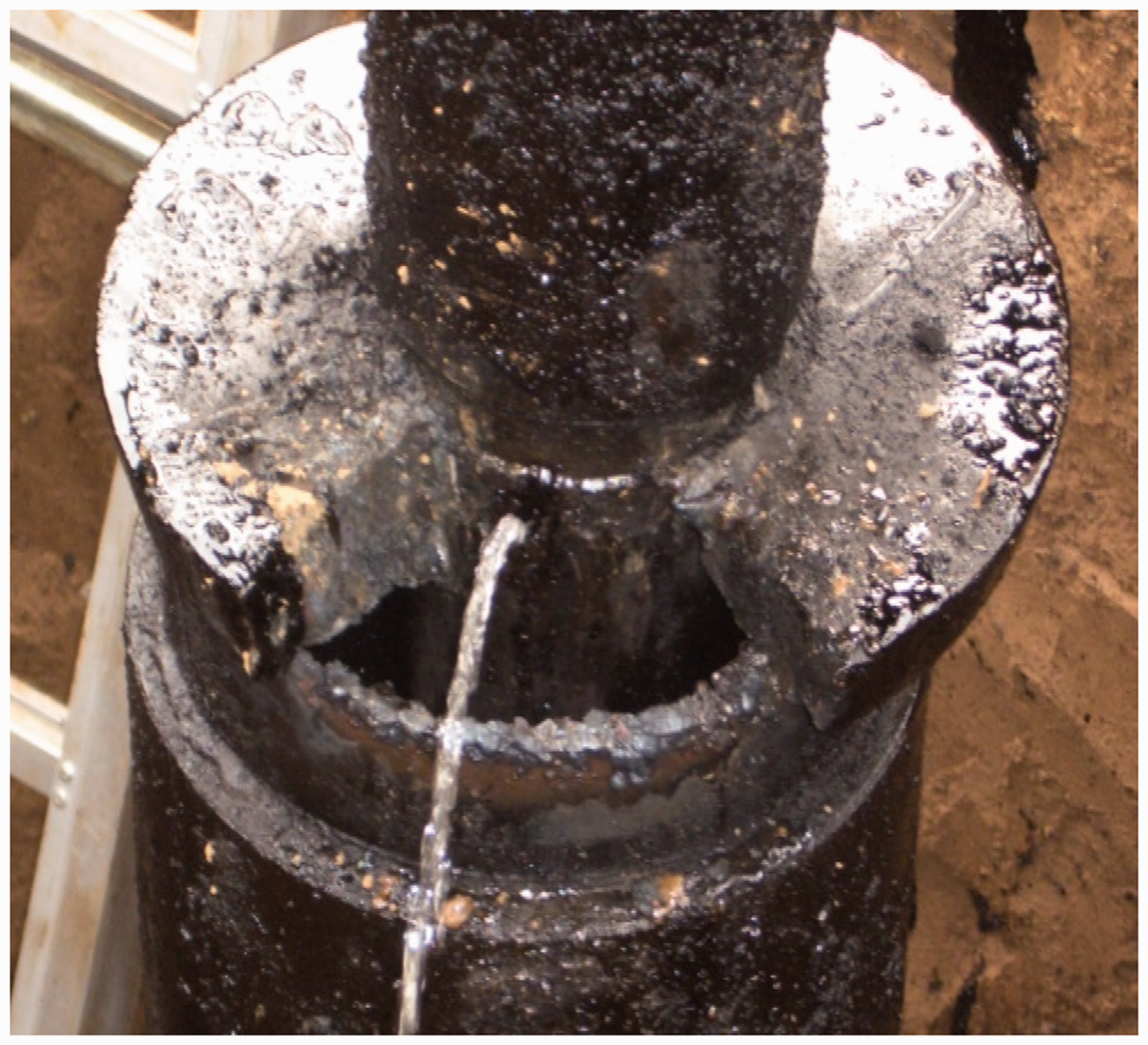
Heavy oil resources constitute the largest reserves of hydrocarbons in the world. However, large amounts of heavy oil reserves remain untapped due to their high viscosity. Heat production has been widely used in heavy oil reservoirs (Inciarte and Nieto, 2003; Mendes et al., 2005; Wu et al., 2005). Many problems occur due to the high temperature of steam injection wellbores, which arises from the unique nature of thermal production. Both steam injection wells and production wells require steam stimulation during the thermal recovery process. Insulated tubing and heat-resistant packing are installed in the wellbore before steam injection to reduce heat loss and protect the casing and cement sheath. However, when the packing fails, the insulated tubing is damaged or aged prematurely because the casing temperature can reach up to 250–300℃ when the steam temperature is 250–350℃. Thus, thermal expansion is restricted, and the compressive stress of the casing exceeds the limit value (Pattillo et al., 2004). When steam injection is stopped, the wellbore temperature decreases, causing the casing to shrink. Residual tensile stress on the casing is produced during the subsequent soaking and production processes. As this process is repeated, the accumulation of residual tensile stress reaches the ultimate tensile strength of the casing and becomes damaged. This phenomenon is particularly notable at the section near the packing, where the casing is directly exposed to high-temperature steam and casing failure is more likely to occur, as shown in Figures 1 and 2. The cement sheath outside the casing is also easily damaged when the wellbore is at high temperatures (Hasan et al., 2005; Kaiser and Yung, 2005; Zhu et al., 2012).
Pipe collapse. Casing leakage.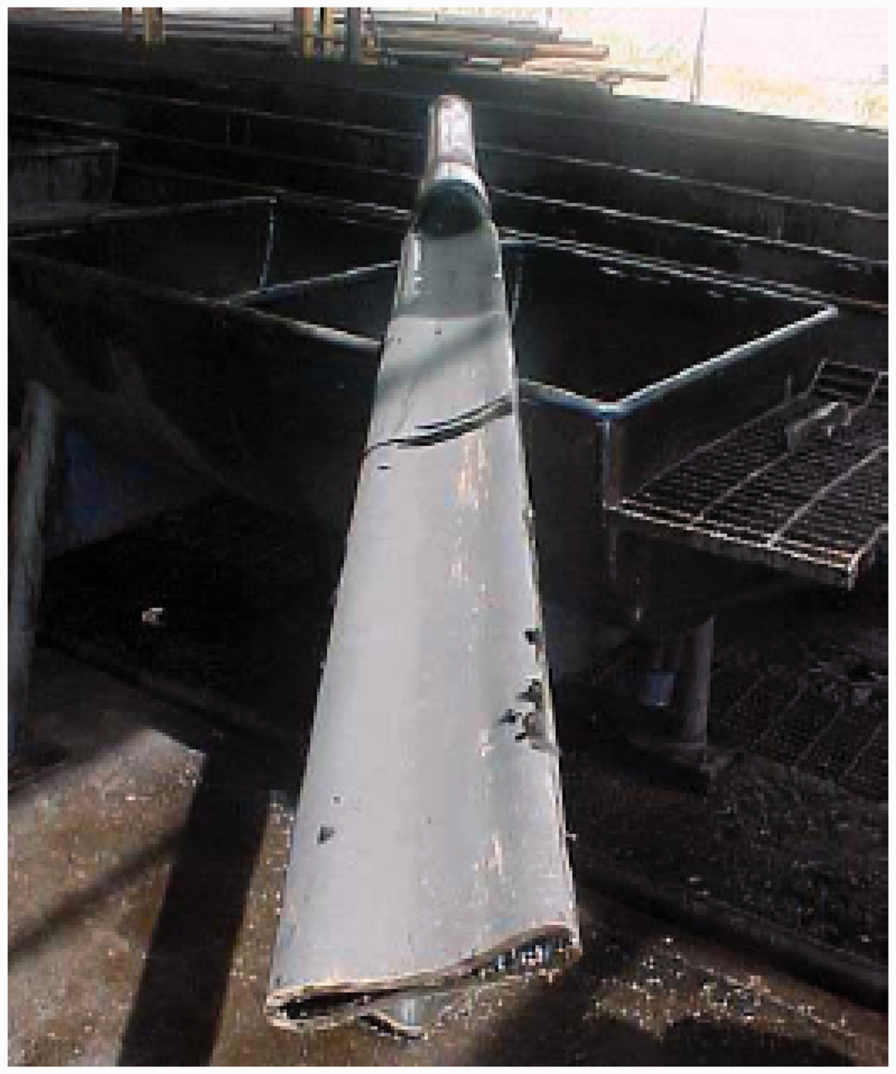
The casing damage was studied in thermal recovery wells by combining the experimental and numerical simulation methods in this paper. Mechanical performance experiments on rock and cement were carried out first, and then a finite element mechanical model of thermal recovery wellbore was established based on thermal-structure coupling. The change rule of wellbore stress with the steam stimulation process was analyzed, and the residual stress of the casing was evaluated (Li et al., 2009; Liu et al., 2010). At last, the relationship between the residual tensile stress,
Mechanical performance experiment of rock and cement
The deformation and strength characteristics of rock and cement in the thermal production well are the essential parameters for studying the casing deformation and the cement failure by finite element numerical simulation. In this paper, some rock cores and cements in XZ oilfield are selected to test their mechanics parameters. These rocks mainly include shaly sand, fine sandstone, medium sandstone, coarse sandstone and mudstone. The test contents of cores and cements include uniaxial tensile test, uniaxial compression test and conventional triaxial test. The contents of the index are tensile strength, compressive strength, elastic modulus, Poisson's ratio, cohesion, internal friction angle.
In order to obtain accurate mechanical properties of rocks and cements, the whole experimental process was carried out in Rock Mechanics Laboratory of State Key Laboratory in Southwest Petroleum University. The experiment standards include ASTM D2664-04 (triaxial test), D2938-95 (uniaxial test), D2936-95 (tensile test) and D4543-04 (rock sample preparation). The experimental equipment is the RTR-1000 triaxial rock mechanics test system of GCTS in the United States, as shown in Figure 3.
RTR-1000 triaxial rock mechanics test system.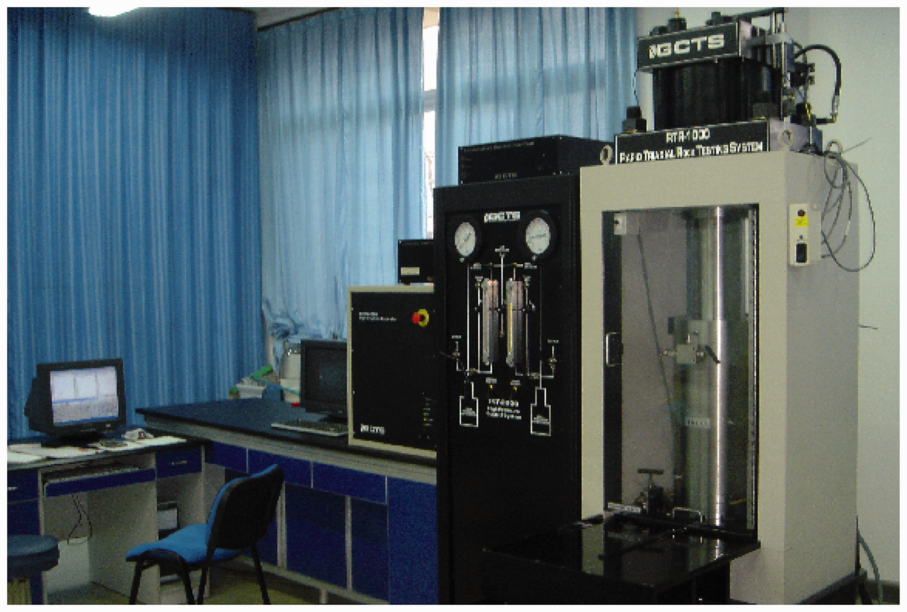
Basic theory and method
Uniaxial compressive strength test
When compression failure of the specimen without lateral pressure occurs under longitudinal pressure, the load on the unit area is called the compressive strength.
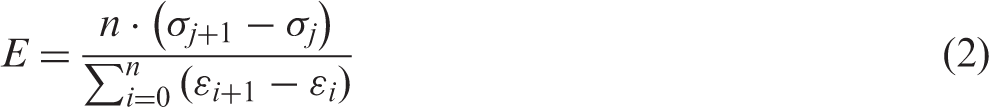
Uniaxial compressive strength of the specimen, R
The elastic modulus of the specimen, E
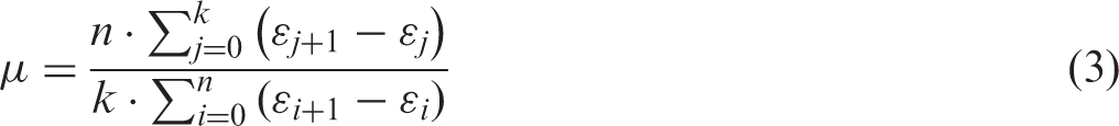
The Poisson's ratio of the specimen, μ
where P is the maximum load when specimen damages. A is the specimen’s cross-sectional area.
where

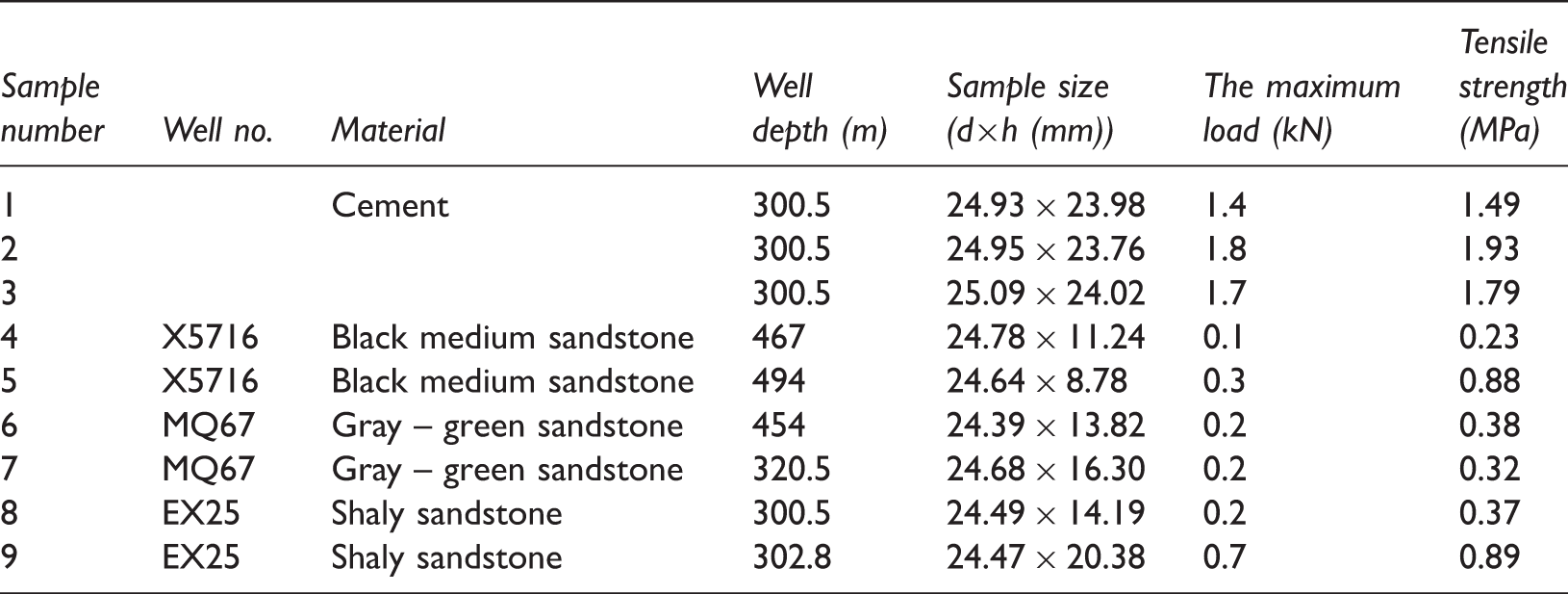
Tensile strength test
The tensile strength refers to the ultimate load on the unit area of the specimen when uniaxial tension failure occurs, which is also the ultimate stress of the rock cohesive failure. Due to the brittleness, weak adhesion and sample preparation difficulties of rocks, the tensile strength of the specimen is determined by the Brazilian method (You and Su, 2004), an indirect method commonly used at home and abroad, shown in Figure 4. The method actually uses the property of the tensile strength of the rock which is far less than its compressive strength.
The Brazilian method.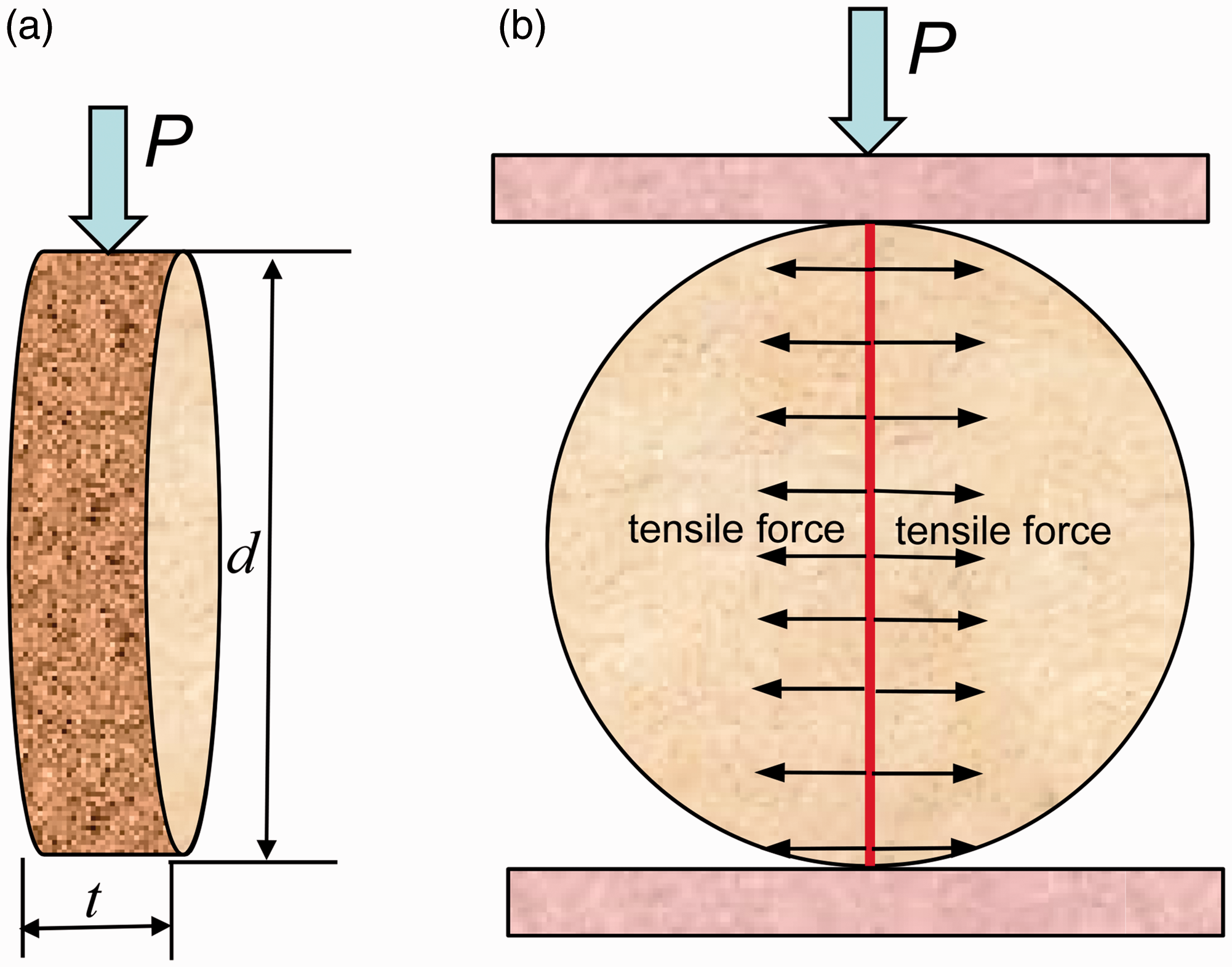

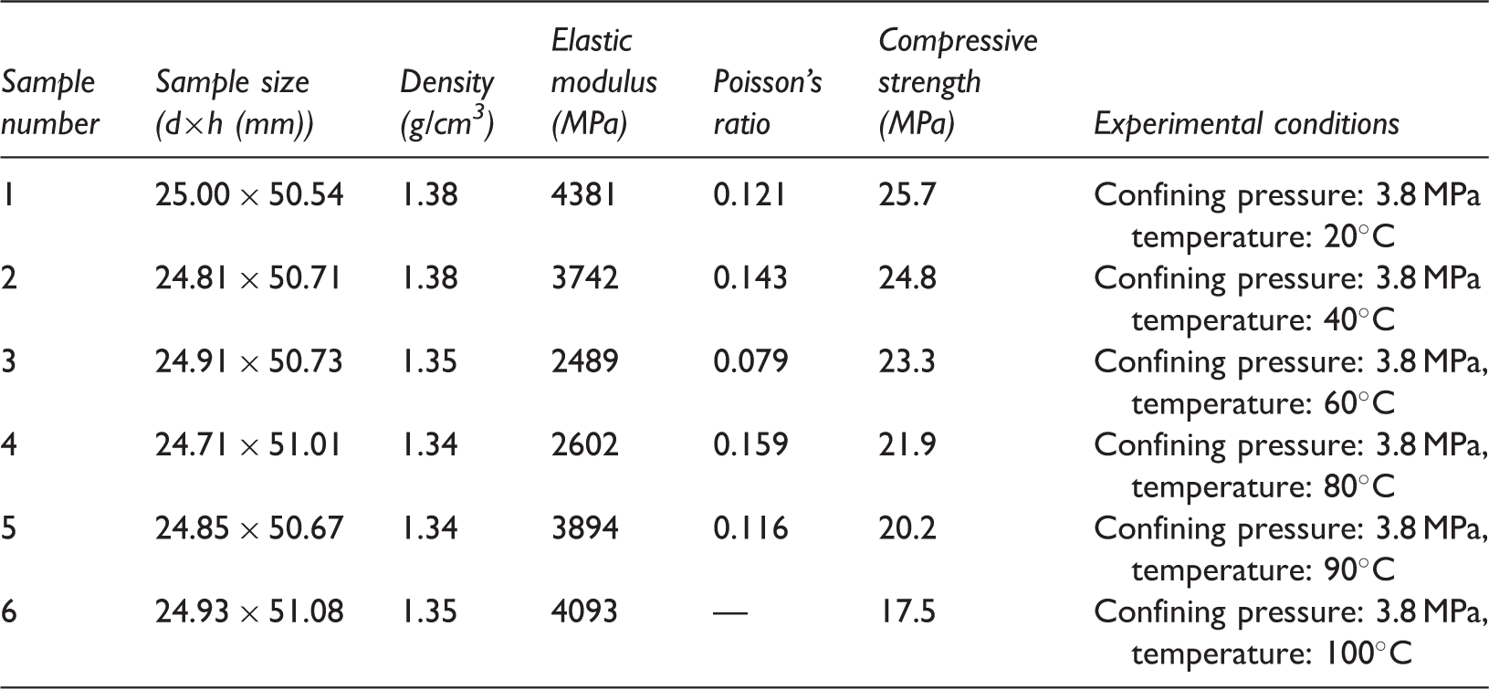
Triaxial compression test
The triaxial test, shown in Figure 5, is used to obtain the compressive strength, elastic modulus, Poisson's ratio, cohesion and internal friction angle of the rock under confining pressure in order to simulate the actual stress state of the rock in the down hole. The determination of the three-axis confining pressure on the rock is carried out according to the method of calculating the lateral confining pressure used in the full-size simulation experiment of the Salt Lake City (Yang et al., 2007), that is, the confining pressure The triaxial compression test.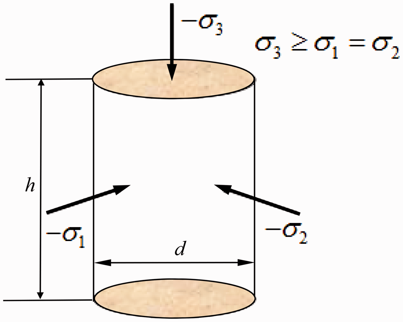
The experimental results
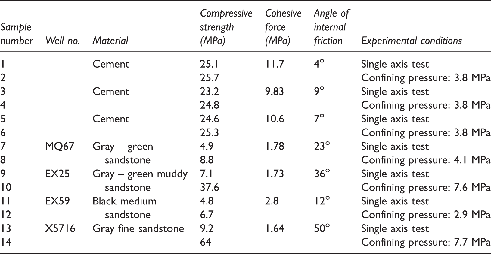
The test results of the compressive strength, cohesion and internal friction angle.
Triaxial test results of cement.
Tensile experimental results of cement and rock.
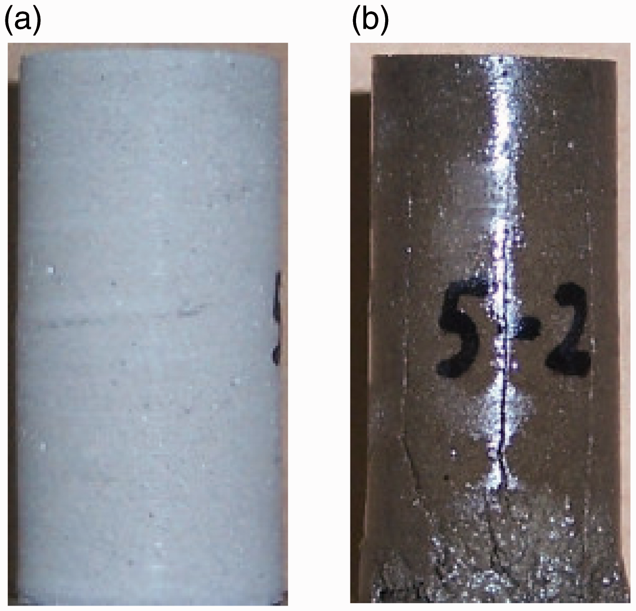
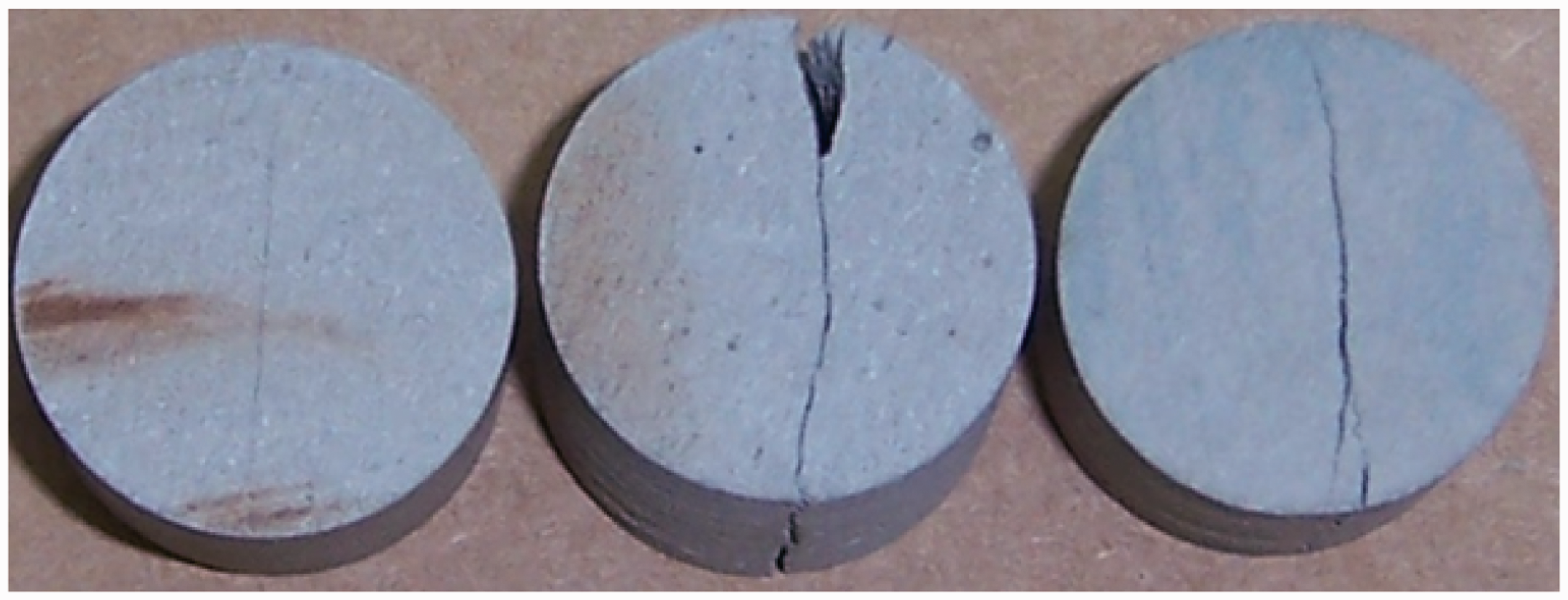
The core and cement sample photos taken after the tests are shown in Figures 6 to 8. There are some fracture lines in the core sample after triaxial test. These fracture lines intersect the axis of specimen. From the results of the tensile test, the fracture lines are along the diameter of the cement specimen.
The core sample before and after triaxial test. (a) before the test, (b) after the test. The cement sample before and after triaxial test. (a) before the test, (b) after the test. The tensile test results of cement.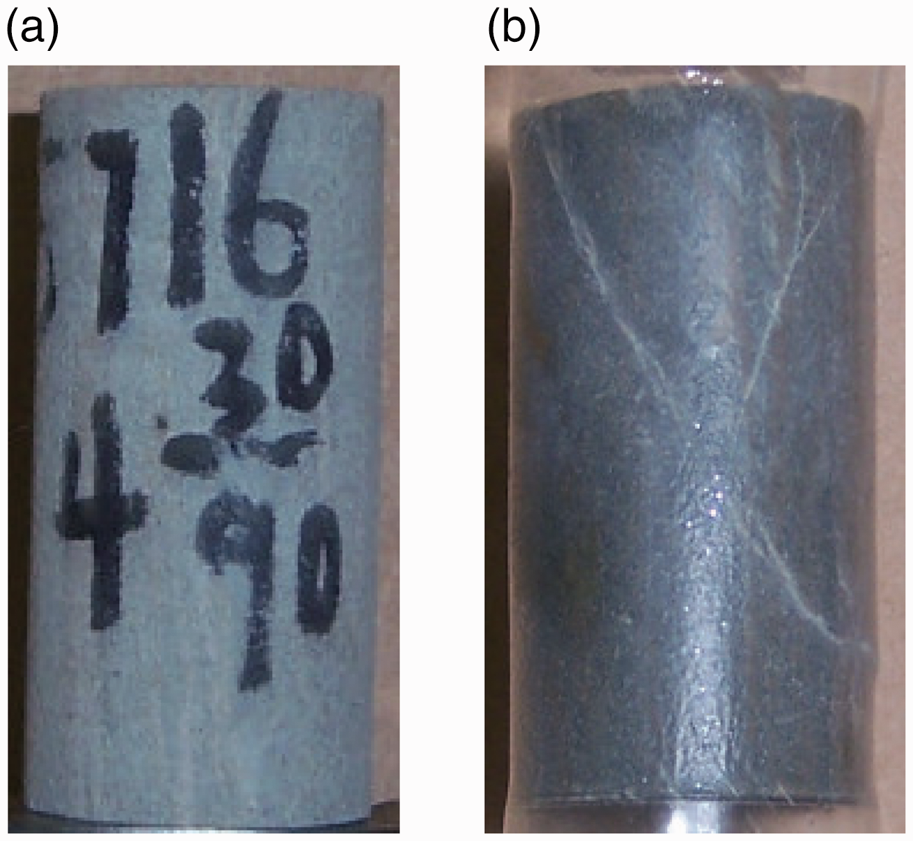
In summary, cement and rock mechanics parameters obtained in the test provide mechanical basic data for following finite element numerical simulation of thermal recovery wellbore.
Basic theory of thermal-structure coupling
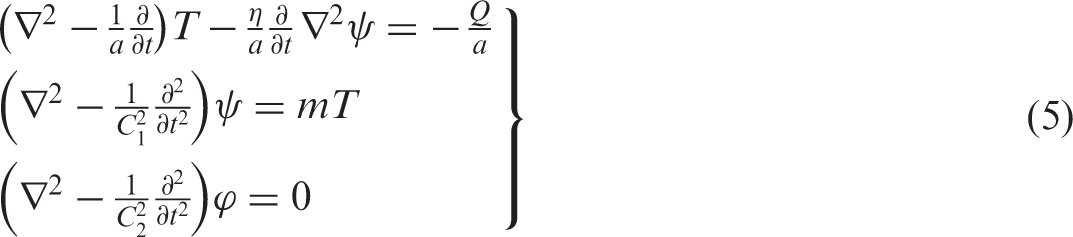
During the thermal recovery process, wellbore temperature changes can lead to changes in materials’ physical parameters (e.g. elastic modulus, Poisson’s ratio, thermal expansion coefficient). Changes in these physical parameters affect the distribution of the wellbore temperature field in turn. Such problems involving the interactions between the stress field and temperature field are referred to as thermal-structure coupling (Lu and Xu, 2011; Yang and Li, 2011). The coupling thermodynamics equation is expressed as follows

Steam injection thermal recovery changes the magnitude and direction of the principal stress of the entire reservoir. Under finite heat and at a stable state, high shear stress and radial stress are produced in the formation during the thermal recovery process. Significant tensile stress can be produced during the heating process when the thermal expansion of the rock is allowed by geological conditions. The local stress leads to shear or tensile failure of the rock around the borehole. This change also affects the mechanical environment of the casing and causes casing failure. Under a constantly changing temperature field, the strain of the wellbore is composed of two components: one caused by in situ stress and another caused by temperature change. According to the generalized Hooke's Law (Huang et al., 2013; Liu et al., 2013; Xiao et al., 2011)
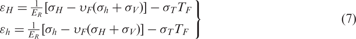
In this study, rock is assumed to be an isotropic body. When temperature changes, vertical stress is rapidly transferred to the formation. Thus, the vertical principal stress can maintain balance with the overburden rock gravity. Because the reservoir boundary can be regarded as infinite, the lateral deformation is restrained, and the lateral strain caused by the temperature change can be regarded as zero. The change in horizontal stress caused by temperature change is expressed as

The lateral deformation of the rock affects the casing and produces additional pressure on it. Additionally, the thermal stress on the casing is generated due to temperature changes

Wellbore thermodynamic finite element model
Thermal-structure coupling is complex when calculating the thermal stress in thermal recovery wells; thus, the wellbore temperature field and stress field were solved based on the finite element numerical simulation. The steam cycling of thermal recovery can be divided into three processes: steam injection, soak and production. Because the temperature change is small and production time is long during the oil production process, the influence of temperature change on the wellbore stress was not considered in the finite element analysis. Therefore, the wellbore temperature and thermal stress field distribution were only studied in the steam injection and soak process. To simplify the analysis, a thermal cycle was considered from steam injection to the end of soak (Qiu et al., 2012; Wang et al., 2013; Zhao, 2012; Zhu et al., 2013).
Grid distortion occurred due to the mesh partition when the complete wellbore model was established, which led to inaccurate analysis results. Thus, a certain interval above the perforation position was used in this study, and an axisymmetric finite element numerical model was established, as shown in Figure 9. The main physical parameters of the wellbore formation materials used for the finite element analysis are shown in Tables 1 to 3.
Axisymmetric model of thermal recovery wellbore.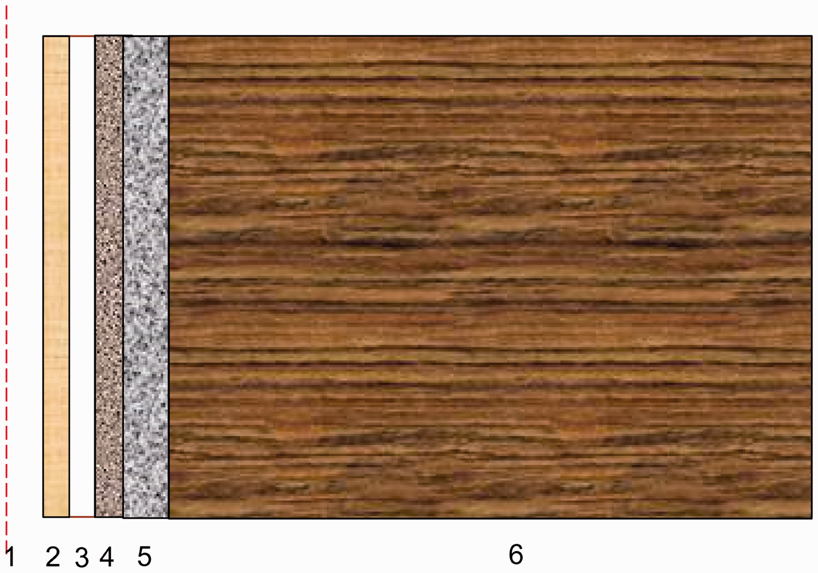
A four-node DCAX4 linear axisymmetric heat transfer unit was used in the analysis of the temperature field. Only the stress distributions of the casing, cement sheath and stratum were analyzed. The influence of steam injection on the tubing was ignored, and an eight-node two-time CAX8R axisymmetric stress-reduced integral unit was used for the stress analysis.
The temperature field distribution of the wellbore section along the formation radial direction was obtained through finite element transient analysis, and the regularity of temperature with time was also obtained. The wellbore temperature was imported into the stress field using the sequential coupling method. Then, the influences of the temperature variation on wellbore stress, the thermal stress change rule of the casing and the cement sheath were obtained.
Analysis of the results
Wellbore thermal stress
In this study, the steam injection temperature is 320℃, and the initial wellbore temperature is 45℃. In the steam injection process, heat enters the injection tubing continuously from the wellhead and passes through the tubing, annulus, casing and cement annulus. It finally arrives at the formation. Then, the temperature decreases gradually along the radial direction of the wellbore. Figure 10 shows the change rule of the casing temperature over time during steam injection. In the initial stage of steam injection, the casing temperature rapidly rises to 271℃ and reaches 296℃ by the end of steam injection. There is no injected heat in the soak stage, and the casing temperature gradually decreases to the initial temperature of the formation.
Curve of casing temperature change with time.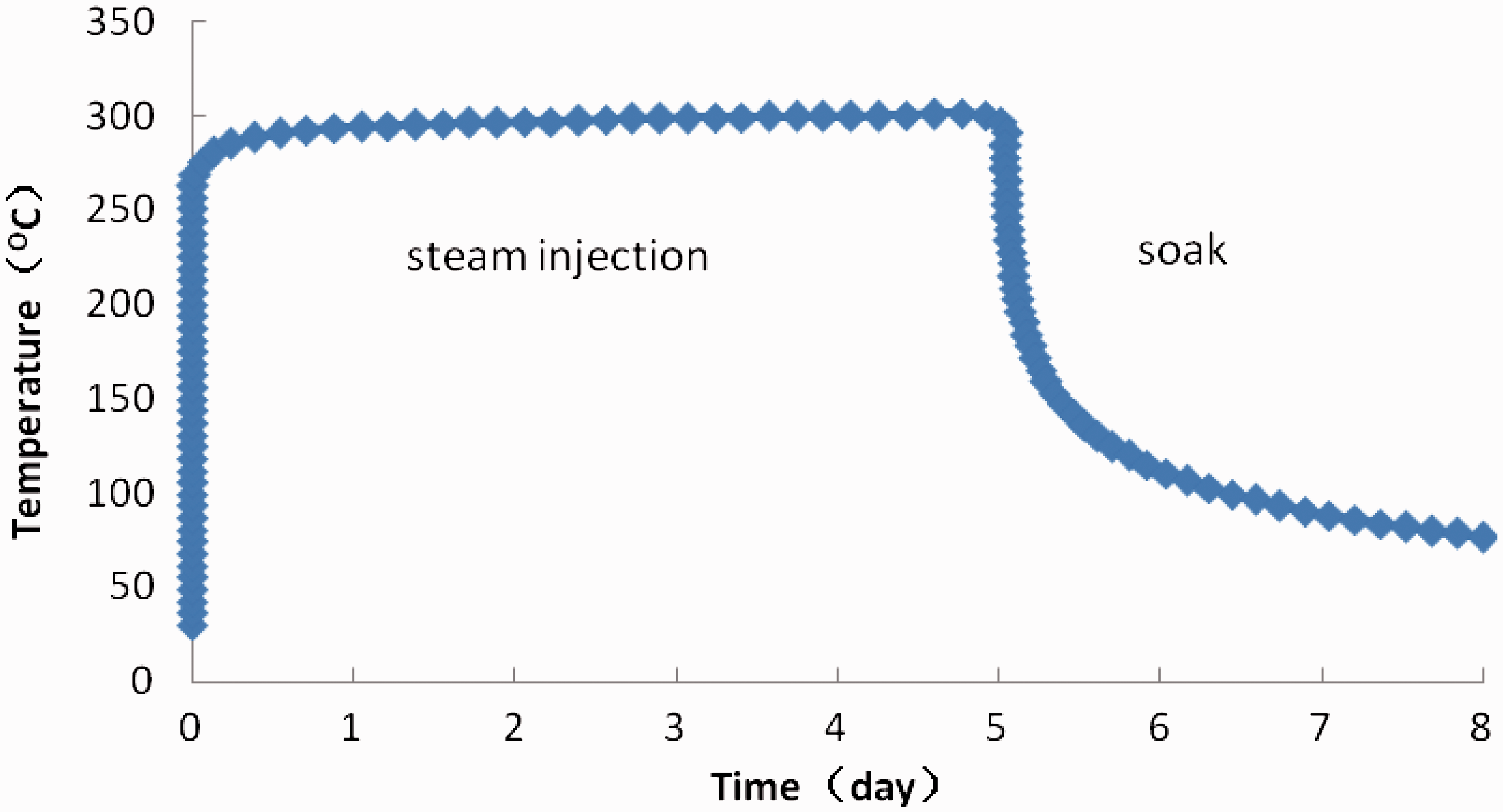
The equivalent plastic strain contour of the cement sheath at the end of steam injection is shown in Figure 11. The maximum equivalent plastic strain appears on the inner wall of the cement sheath, also known as the first interface. When the cement quality is good, there are differences in the thermal expansion coefficient between the cement sheath and casing. The casing and cement sheath extrude each other due to different thermal expansion rates, producing significant strain on the inner wall of the cement sheath.
Equivalent plastic strain contour of cement sheath at the end of steam injection.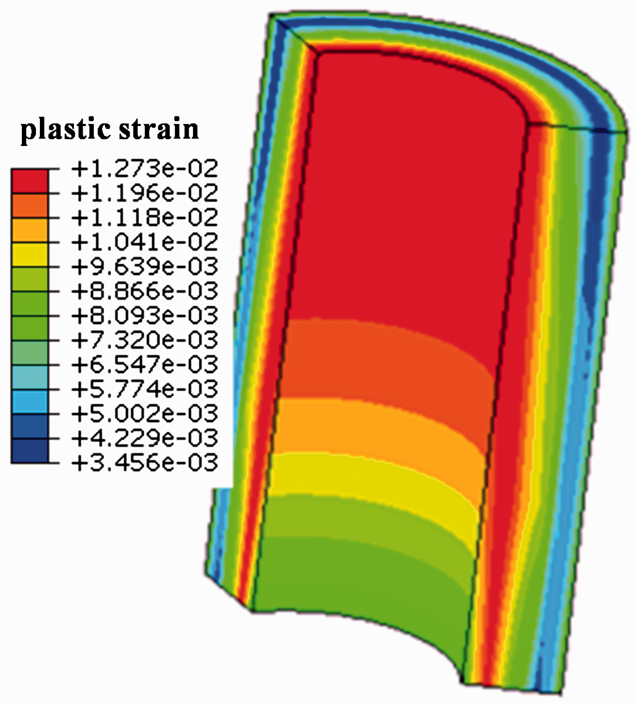
The curve of the equivalent plastic strain of the inner wall of the cement sheath over time is shown in Figure 12. With an increasing number of stimulation cycles, the equivalent plastic strain increases cumulatively, and the probability of damage to the cement sheath also increases. The cement sheath breaks when the equivalent plastic strain reaches a certain value, causing the cement quality to decline and the isolation ability to fail, preventing subsequent steam stimulation operation. Cement sheath damage will also lead to simultaneous casing deformation and failure. When the casing damage reaches a certain point, production tools cannot be transported into the well, which often leads to abandonment.
Curve of equivalent plastic strain of the inner wall of cement sheath with time.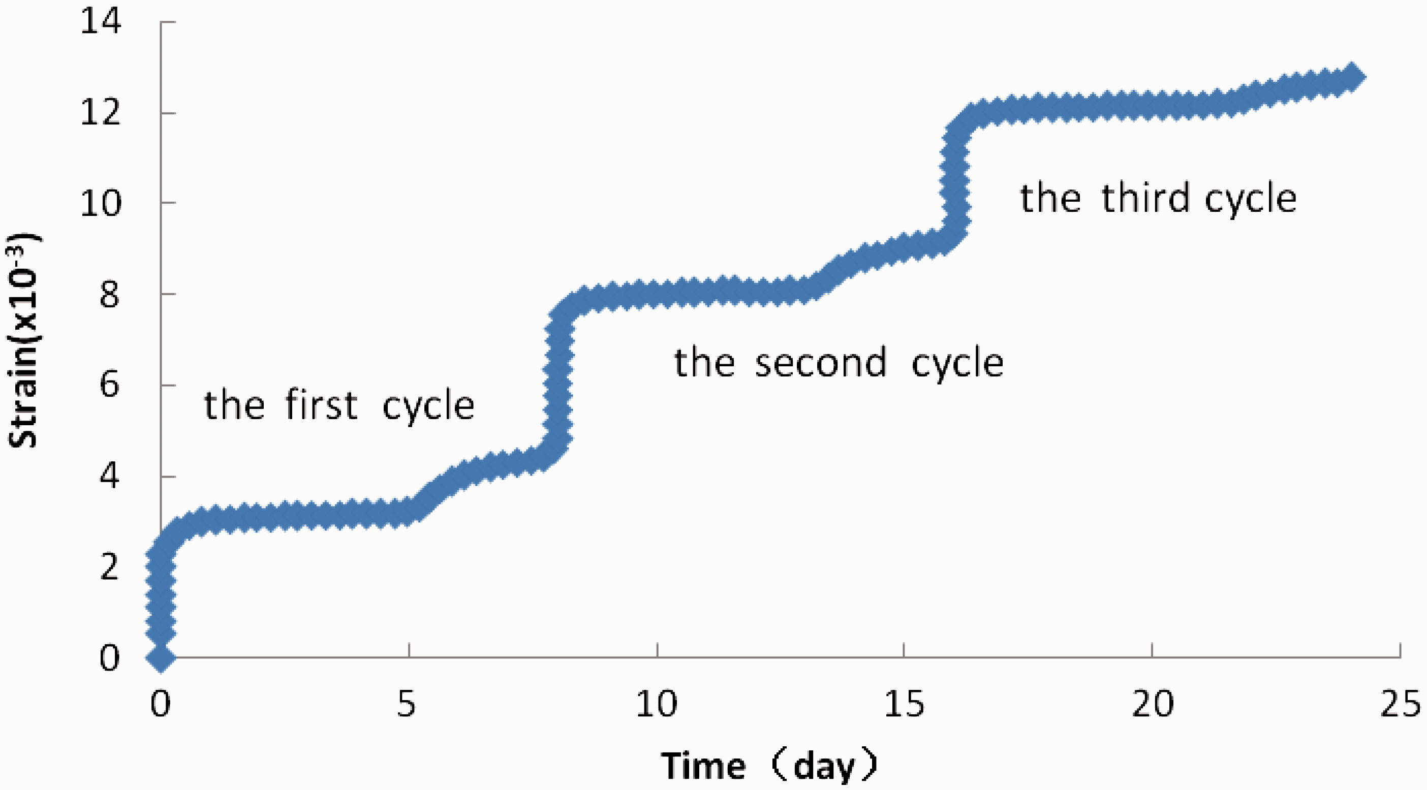
Rock deformation occurs near the wellbore due to thermal stress during steam stimulation. After cementing, in situ stress reaches a new equilibrium. During thermal recovery, thermal expansion of the rock occurs due to the change in the temperature field, and the original in situ stress field is destroyed. Local plastic deformation is produced by the driving force of the thermal stress. The equivalent plastic strain of the rock is shown in Figure 13. The local deformation of the rock affects the cement sheath and casing and leads to casing deformation and failure.
Equivalent plastic strain contour of rock.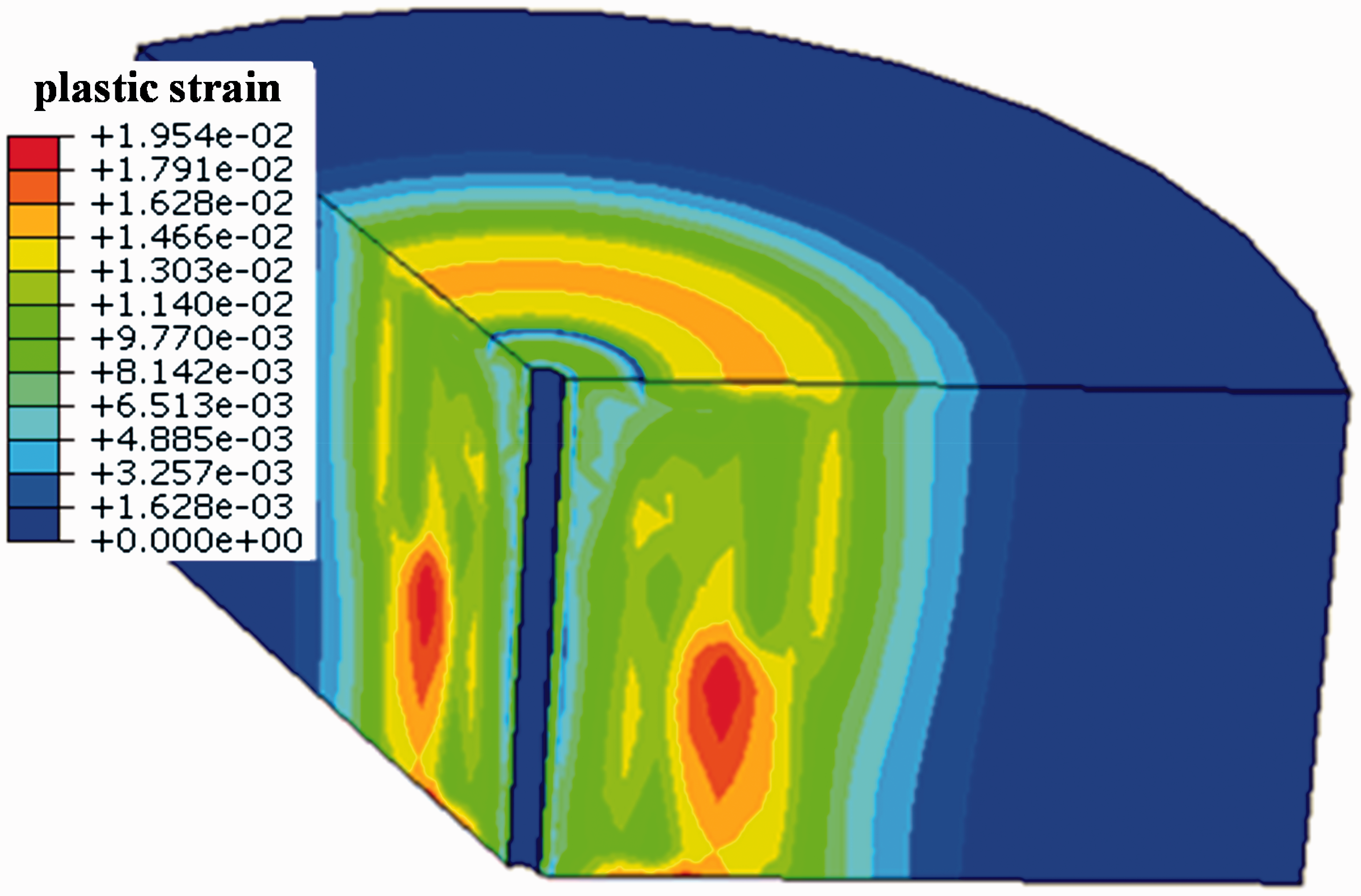
Residual stress of the casing
The forming process of residual stress on the casing can be analyzed clearly in the thermal production well, combining theories in material mechanics and thermodynamics.
Because the casing is sealed in the cement, its thermal expansion and contraction are limited when temperature changes. But thermal stress in the casing changes with temperature. As shown in Figure 14, its OA-line suggests that compressive stress of casing goes up with the rising temperature. Certainly, residual stress will not be generated in the casing if the thermal stress resulted from temperature rising does not exceed its yield stress. When the temperature drops down, the stress returns to the O-point along the AO-line. On the contrary, stress on casing continually increases along the AB-line after exceeding the yield strength. Larger compressive stress will be produced if temperature increment is excessively large. Casing and cement sheath separates from each other and causes high temperature steam channeling when cementing strength between the casing and cement is poor at this time. Stress status of casing is still kept at the B-point, if the temperature difference is not changed before casing damage. At the stage of soak, casing’s temperature declines and its stress varies along the BC-line. When compressive stress of casing drops to zero, the temperature of casing has not still fallen back to the original value. As the casing temperature continues to decrease, tensile stress is generated in the casing and varies along the BC-line. When the stress reaches the point C (tensile yield point of casing), temperature continues to decrease, and then stress varies along the CD-line. When the temperature drops to the initial value, the residual tensile stress is generated on casing. If this stress exceeds the tensile strength of the casing, casing is broken. This is the first steam injection cycle of casing stress varying with the temperature.
Forming mechanism of residual thermal stress.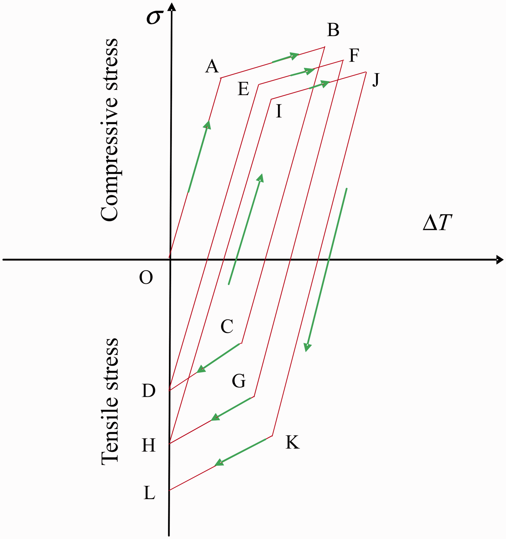
If the casing is not damaged during the first steam injection cycle, the stress status of casing changes from point D to point E along the DE path as the casing temperature increasing during the second cycle. Because of the Bauschinger effect, the stress of casing cannot reach the AB-line, the yield value is reached at the point E, then casing stress varies along the EF-line after yielding. When the temperature of the second steam injection stage is at the highest value, the stress of casing gets to F point, and compressive stress of F point is lower than B point’s value. Similarly, after the second cycle is completed, residual tensile stress (point H) on casing is generated and its value is larger than the D point’s value of the first cycle. The stress and temperature of the cycle are shifted to the direction of tensile stress. As the increasing of steam injection cycles, the residual stress value of casing is bigger than once, which leads to the damage of casing finally.
In the finite element analysis of this study, the steam stimulation cycle is n (n>5), and the input parameters of each cycle are identical. The curve of the change in casing axial stress over time is shown in Figure 15. Tensile stress is positive, and compressive stress is negative; these values are used to analyze the change rule of the casing axial stress. The stress on the casing increases rapidly with steam injection and exceeds the yield strength of the casing material. At the final stage of steam injection, the casing axial compressive stress reaches the maximum value of −610 MPa. Axial compressive stress on the casing decreases during the soak period. When the casing temperature is close to the initial formation temperature, the axial stress transforms from compressive to tensile stress. At the end of the first cycle, the residual tensile stress on the casing is 63.62 MPa. With an increasing number of thermal cycles, the stress curve moves in the tensile direction and the residual tensile stress increases gradually. The residual stress on the casing reaches 151.2 MPa at the end of the fifth cycle. The residual stress reaches 593.41 MPa after the 11th cycle, which exceeds the yield stress of the casing (551 MPa) but does not reach the ultimate strength of the N80 casing (741.85 MPa). Finally, after the thirteenth cycle is completed, the residual stress is 749.44 MPa. This value exceeds the ultimate strength of the N80 casing, thus, the casing may be destroyed.
Change curve of axial stress on casing with time.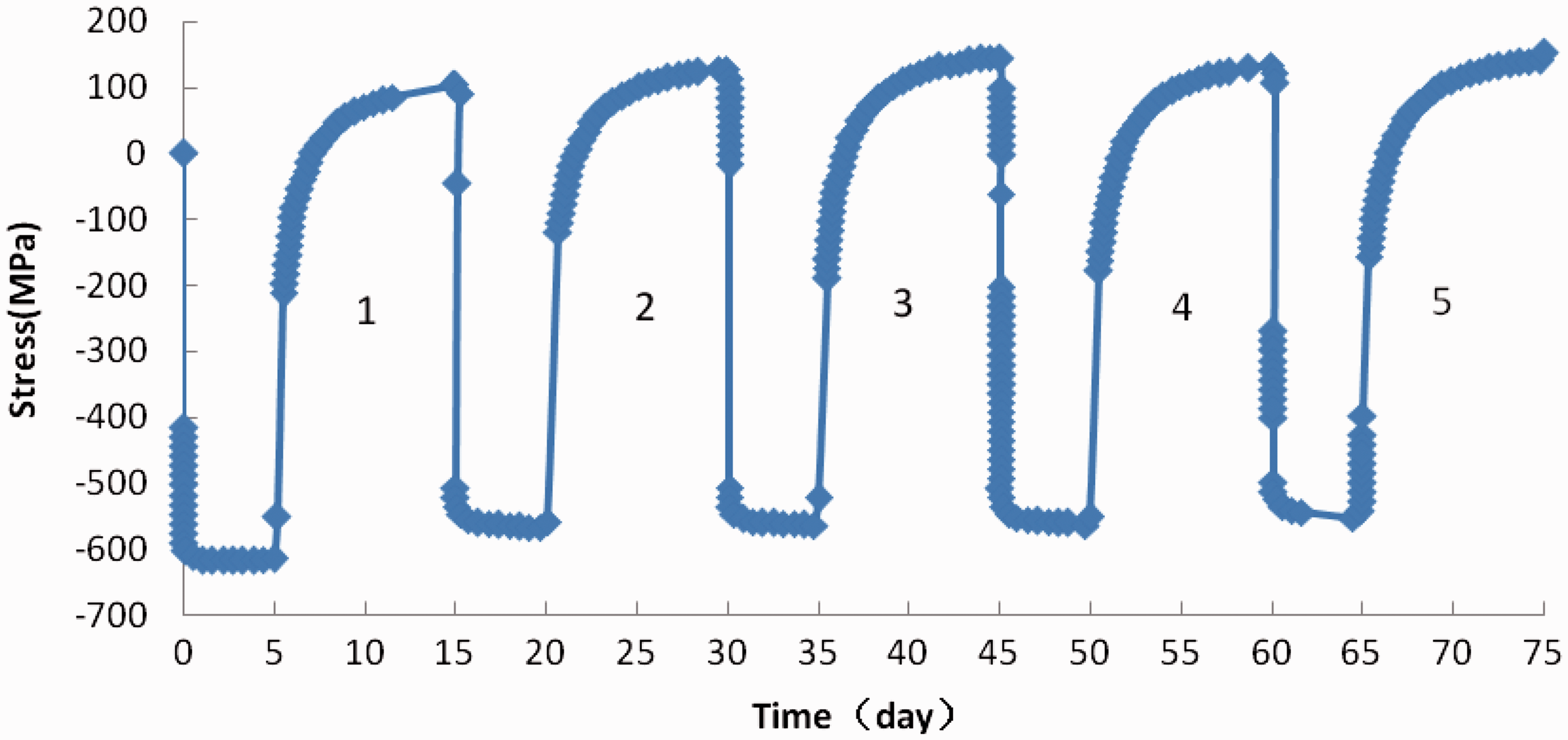
Temperature changes and the casing material have significant influences on the residual stress. As the casing temperature increases, the residual stress increases. If higher-grade steel is used for the casing, which has a higher yield strength and ultimate strength compared to lower-grade steel, more steam stimulation cycles are needed to achieve the ultimate strength of the casing, and the probability of casing damage is lower according to the above theoretical analysis based on numerous finite element simulations and calculations. Finally, the relationship between the residual tensile stress, 
Equation (10) is applied to the evaluation and analysis of the residual stress in 13 cycles. Equation (10) is no longer suitable for use after 13 cycles.
There are two strength indexes for the casing material: the yield stress, Stress–strain curve of casing material.
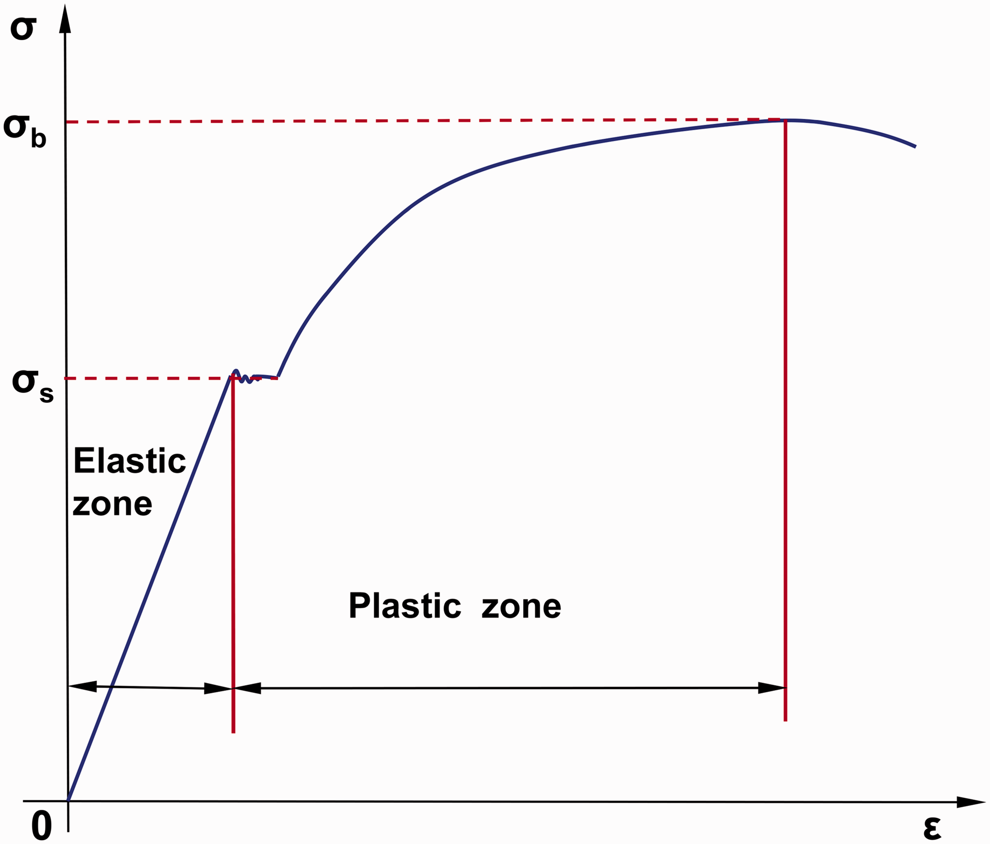
If the remaining strength 
If the ultimate remaining strength is zero, then the casing is broken or even fails completely. In this manner, the maximum number, n, of steam injection cycles for safe production is obtained.
Example analysis
Residual stress evaluation on the casing in a thermal production well.
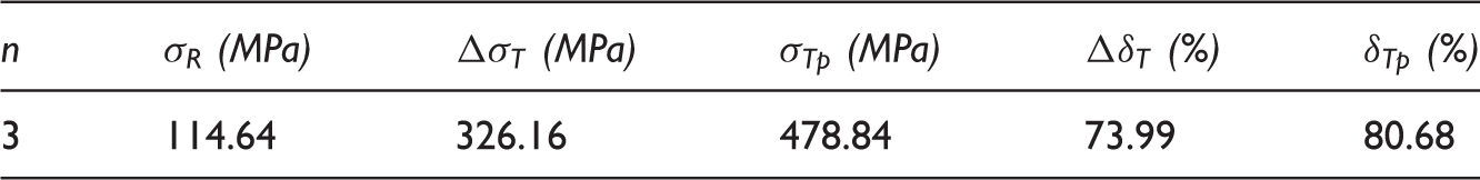
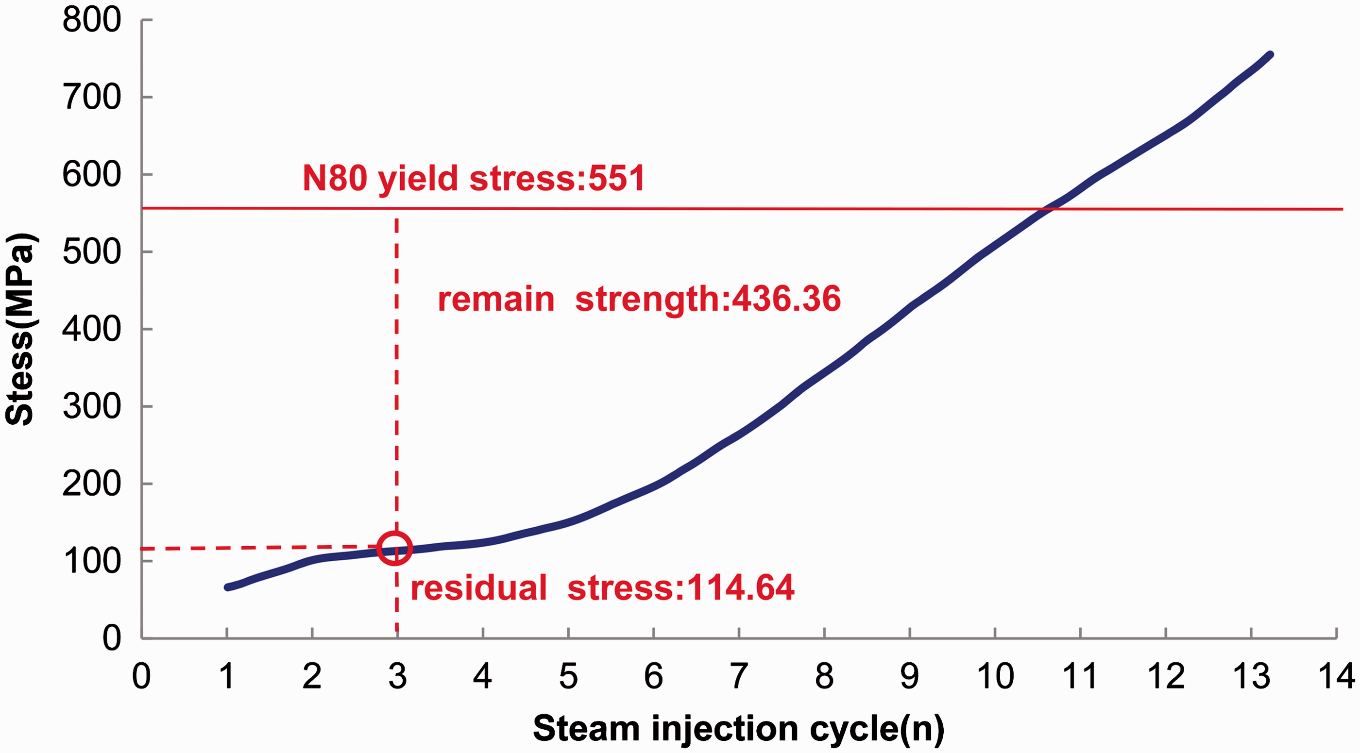
Relationship between residual stress of casing and steam injection cycle.
Conclusions
Mechanical performance experiments on rock and cement are carried out, and the test results provide mechanical basic data for following finite element numerical simulation of thermal recovery wellbore. Thermal-structure coupling is complex when calculating the thermal stress in a thermal recovery wellbore. In this study, finite element numerical simulation technology is used to establish a finite element mechanical model of the thermal recovery wellbore. The wellbore thermal stress is analyzed, and the residual stress of the casing is evaluated by solving the model. The results of the study provide a theoretical basis to establish reasonable preventative measures for casing damage in thermal recovery wells. The casing temperature rises sharply during steam injection, and the casing temperature decreases gradually to the initial temperature of the formation with increasing soak time. The thermal expansion rate of each material is different in the wellbore; thus, the casing and cement sheath extrude each other, and a large strain is produced on the inner wall of the cement ring. The local deformation of the rock affects the cement sheath and casing, which can lead to casing deformation and damage. Through a large number of finite element simulations and calculations, the relationship between the residual tensile stress,
Footnotes
Declaration of conflicting interests
The author(s) declared no potential conflicts of interest with respect to the research, authorship, and/or publication of this article.
Funding
The author(s) disclosed receipt of the following financial support for the research, authorship, and/or publication of this article: The authors are grateful to the support from the National Natural Science Foundation of China (No. 51574198).