
Abstract
A gusher from accident well 37 at the Tengiz oilfield (Kazakhstan) led to a catastrophic fire and produced melt combustion metamorphic rocks in its thermal halo (aureole). According to the obtained data on the mineralogy and petrology of the combustion metamorphic rocks and inferred thermal conditions of metamorphism, the protolith sand and clay can become fully molten at a temperature no lower than 1200℃. Four models have been tested for the thermal effect of the Tengiz fire on the country rocks: (a) a single straight-flow vertical gas flare, (b) a single vertical gas flare with oil droplets, (c) a single oil–gas flare with lateral wind load, and (d) a composite oil–gas flare consisting of one vertical and two horizontal spouts. Modeling with SigmaFlow software takes into account the spatial turbulent airflow mechanics of the flare, convective, and radiative heat transfer, burning of gas and oil droplets, as well as conductive heat flux in soil. Model 4 simulates the best the Tengiz fire in the period from 26 June 1985 to 05 September 1986. As the model predicts, a flare with the parameters as in the Tengiz case can cause partial melting of sedimentary material (1100℃) in a local zone but cannot maintain its bulk melting which requires higher temperatures (1200–1400℃). Additional heat may have come from ignition of oil spilled over the surface. The heat from a single oil–gas flare from a wellhead with a 0.5-m stickup turns out to be insufficient for combustion metamorphism (T = 1000–1400℃).
Introduction
Many petroleum reservoirs of any age from Precambrian to Pleistocene include zones of abnormal pressure (reservoir overpressure) at different depths (Chilingar et al., 2002; Kholodov, 1983; Melik-Pashaev et al., 1983). High reservoir pressure can provide oil enhancement and is generally favorable for production, but it is fraught with blowout emergency risks and the ensuing mitigation costs (Akhmetov, 2007; Khakzad et al., 2014; Melik-Pashaev et al., 1983). Overpressure can release naturally in mud volcanism in provinces of abundant emission of hydrocarbon gases, mainly methane (Aliev et al., 2009; Babayev et al., 2014; Chilingar et al., 2002; Kopf, 2002, 2003; Levorsen, 1967; Planke et al., 2003; Shnyukov et al., 2005; Svensen et al., 2003; Svensen et al., 2004). Large eruptions of mud volcanoes in some territories (Apsheron and Taman peninsulas, Caspian and Azov Seas, Burma, and Trinidad) are likewise often attendant with spontaneous ignition of methane gushers and fires. The life span of fires is inversely proportional to the flare size (Figure 1): great flares, up to 400 m high, decay in half an hour, while large ones from 50 m to 150 m can burn for hours. Ignition maintained for months or even years was reported only for small flares of gas venting through systems of connected fractures (Aliev et al., 2009; Bagirov and Lerche, 1998; Bagirov et al., 1996; Kovalevsky, 1940; Lerche and Bagirov, 1999; Rakhmanov, 1987; Shnyukov et al., 2005).
Size of methane flare versus its life span observed in fire eruptions of mud volcanoes after Aliev et al. (2009), Kovalevsky (1940), and Rakhmanov (1987).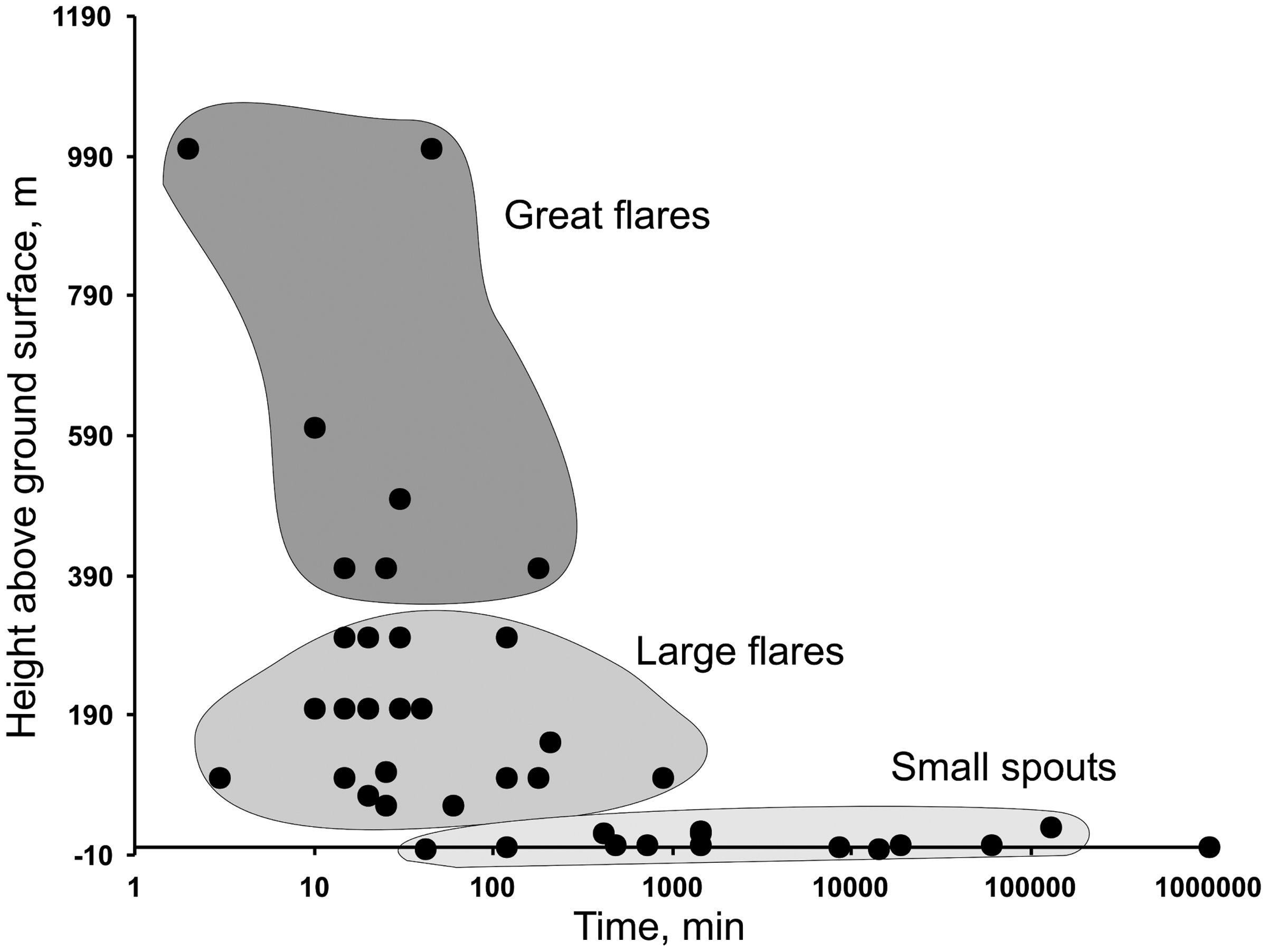
The role of methane fires as sources of thermal (combustion) metamorphism has been recognized only recently, though the earliest interpretation of thermal metamorphic haloes of ultrahigh-temperature and low-pressure rocks dates back to the 1930s (Kovalevsky, 1940; McLintock, 1932). Combustion metamorphism (CM) produces holocrystalline high-Ca paralavas (containing pseudowollastonite, β-Ca2((Si,P)2O4) or α-Ca2((Si,P)2O4) solid solutions, nagelschmidtite, fluorellestadite, Ca ferrites and titanites), as well as glassy Ca and Ca–Na paralavas (Basi and Jassim, 1974; Grapes, 2011; Grapes et al., 2013; McLintock, 1932; Seryotkin et al., 2012; Sharygin et al., 2006; Sokol et al., 2008, 2010, 2012, 2015). These mineralogically and chemically particular rocks may form uniquely by burning of the most highly calorific fuel, such as petroleum, and are thus indicators of past oil and gas seeps.
Currently there are no models available which would allow quantitative comparison of the gas flare parameters with the sizes, configuration, and temperature zones of thermal metamorphic haloes. Meanwhile, significant advance has been achieved in pure and applied issues of thermal physics concerning combustion of gas mixtures, which can be used to model the origin and evolution of gas fires (Akhmetov, 1994, 2007; Kuznetsov and Konopasov, 2008).
We undertook such kind of modeling for the case of a thermal metamorphic halo formed around well 37 at the Tengiz oilfield (Kazakhstan), where drilling of a pressurized reservoir in June of 1985 led to accidental 200-m high gusher of oil and gas rising from the depth of more than 4 km and subsequent spontaneous fire that lasted 13 months. The availability of detailed published and video evidence of the accident and the flare structure allowed us to choose boundary conditions for formulating and solving the related problems of thermal physics and air dynamics proceeding from a real geological setting.
In this article, we report mineralogical and petrological features of fire-induced melt rocks and reconstruct the conditions of their CM. As a result of modeling with the SigmaFlow software for the specific case of CM mineral formation, the burning oil–gas flare has been interpreted, for the first time, as a heat source for near-surface CM. The geometry of the thermal fields left by such fires has implications for boundary conditions required for the formation of high-temperature metamorphic haloes from similar heat sources.
The Tengiz oilfield
Overpressure widespread in the reservoirs of the Caspian province gives rise to mud volcanism, maintains open fractures at large depths, and poses technological problems to petroleum production. Drilling through pressurized reservoirs may lead to uncontrolled oil and gas release in gushers and long-lasting catastrophic fires (Kholodov, 1983; Melik-Pashaev et al., 1983), as it happened in June 1985 at well 37 of the Tengiz oilfield.
The Tengiz oilfield (Western Kazakhstan) is located near the side of the Caspian basin within a large isometric Early-middle Carboniferous reef buildup, about 400 km2 in surface area, with oil in a subsalt reservoir (23 × 17 km on the subsalt top, with the uplift height about 1000 m). The reservoir consists of Early Permian (Artinskian), Middle Carboniferous (Bashkirian), Early Carboniferous, and Late Devonian organic carbonates that total a thickness of 3500 m. The oil–water interface has not been detected. The reservoir is producing from the Lower and Middle Carboniferous sediments stripped at the depths 3900–5000 m. The sediments are lithologically variable, with alternation of thin limestone layers that differ in structures and textures, as well as in characteristics (porous, porous-fractured, porous-vuggy-fractured, and fractured reservoirs).
Note that although the reservoir spreads deeper than 5 km, it is mostly porous, while long, open fractures provide its connectivity. The formation pressure in the pay zone (81–93 MPa) is 1.8–2.0 higher than the hydrostatic pressure. The oil is waxy, low-resin, with the density 0.805 g/cm3 and 0.45–1% S. The oil accumulation contains solid bitumen. Gas consists of 20% H2S and 10% of CO2. The daily flow rate exceeds 100 m3. Recoverable resources count from 750 × 106 to 1125 × 106. The predicted oil-in-place resources reach 3133 × 106 tons of oil, and the resources of associated gas are 1.8 × 10¹² m3 (Abdulin et al., 1993; Bagrintseva, 1999; Maksimov, 1987; Mikhailov, 1990; Vadetsky, 2004; Weber et al., 2003).
Data and formulation of the thermophysical problem
As the Tengiz fire at well 37 progressed (25 June 1985–27 July 1986), it remained similar to natural gas flares, though the combustion style changed. Unlike the natural blowout events, the parameters of technological gushers necessary to specify the boundary conditions for thermophysical modeling were known. Our objective was to simulate oil and gas combustion in flares of different geometries, which existed in the real case of the Tengiz accident, as well as the related surface thermal fields.
Accident history
We studied the accident history from the documentary by Gonopolsky (1988), the paper by Lyubin (2012), and eyewitness reports of people who were present at the site and those who participated in the emergency cleanup (Potapov, 1994). This inventory was of special importance for appropriate problem formulation as it allowed specifying boundary constraints most closely corresponding to the real flare parameters.
On 23 June 1985, drilling of well 37 on the slope of a reef buildup in the western Tengiz oilfield accidentally provoked a gusher of oil and gas from a depth of 4467 m and a catastrophic fire (Feldman et al., 1996; Lyubin, 2012; Potapov, 1994, 1996). The accident was caused by a technological trouble when the drilling tool was lifted to 3500 m in the conditions of circulation loss while the drilling mud flew through the reservoir and the expulsed oil–gas mixture became released from the tool in a 14–15 m spout.
The gusher, which was originally a single vertical spout of unknown geometry, ignited spontaneously on 25 June 1985, at 15:30 during preparation for the emergency termination of the blowout preventor. The pressure at the head of the accident well exceeded 100 bar. Already 15–20 minutes later, the rig metal structure deformed under high temperature and collapsed having barred the well collar. Once the preventor failed, three spouts rising in different directions appeared instead of a single flare: a 50- to 60-m high vertical spout (from the hole) and two 12- to 40-m high horizontal ones (from the casing annulus). Oil spilled on the surface and ignited over an area of ∼500 m2 (Lyubin, 2012) (Figure 2a). The first stage of the accident lasted from 25 June 1985 to 05 September 1985. In a month, the composite triple flare produced a “lake” of molten sedimentary rocks in its hottest zone (with the well at the center). Then the melt quenched into glassy rocks of diverse bright colors (Feldman et al., 1996; Potapov, 1994, 1996).
Oil–gas fire at accident well 37, Tengiz oilfield, Kazakhstan after Lyubin, (2012). (a) Composite oil–gas flare associated with deformation of drilling facilities. The flare consists of one 50–60 m high vertical spout and two horizontal spouts, from 12- to 40-m long. Ignition covers an area of 450–500 m2. Period from 25 June 1985 to 05 September 1985; (b) single vertical flare that formed after cleaning up the well mouth. The flare is 165–200 m high and 50 m wide on the top. Period from 10 September 1985 to 27 June 1986.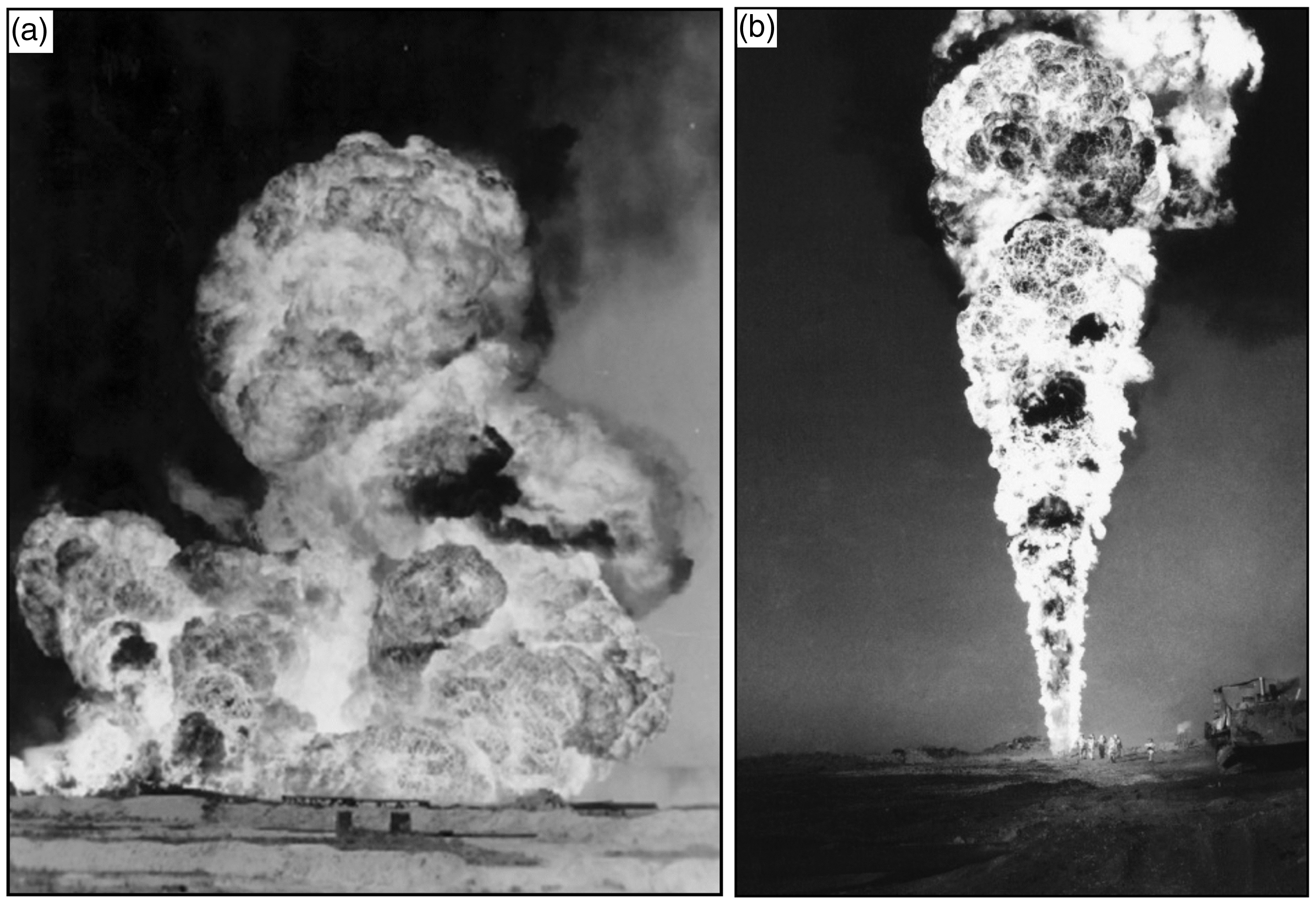
The air around the well was cooled down by a water curtain. Soil wetting with seawater produced salt encrustation and swamping. The collapsed drilling assembly was shot between 5 and 10 September 1985 in order to cleanup the well head and liberate mechanically the burning oil gusher which thus transformed into a single vertical flare. Since then, the fire passed to its best documented second and final stage that lasted 11 months, when the flare took the shape of a narrow 165- to 200-m high cone with the maximum width of 50 m (Figure 2b). The flame changed in color from white at the bottom to orange and purple at the top surrounded with blue back smoke clouds. The gusher’s daily flow rate was about 10,000 tons of oil and two million cubic meters of gas (Potapov, 1994). The oil that spilled on the surface during the first fire stage began to burn in the gusher (Gonopolsky, 1988) thus increasing the flare temperature to 2000℃, according to estimates by an optical pyrometer (Feldman et al., 1996). Oil blew out from the casing flange rising 0.5 m above the earth (Lyubin, 2012). This stickup height was used later in modeling to constrain the flare position relative to the ground surface. The air and ground temperatures were, respectively, 175–190℃ and 390–410℃ at the well head and decreased away from it to 140℃ and 200℃ at 80 m and on to 110℃ and 180℃ at 130 m, respectively (Figure 3).
Distribution of combustion products and locations of temperature (air and ground) measurements relative to the single vertical flare. Model corresponds to accident period from 10 September 1985 to 27 September 1986, after Potapov et al. (2001) and Lyubin (2012). 1 = tengizites; 2 = mesolites; 3 = tengizite clasts; 4 = mesolitic sandstone; 5 = fresh clayey sand and silt.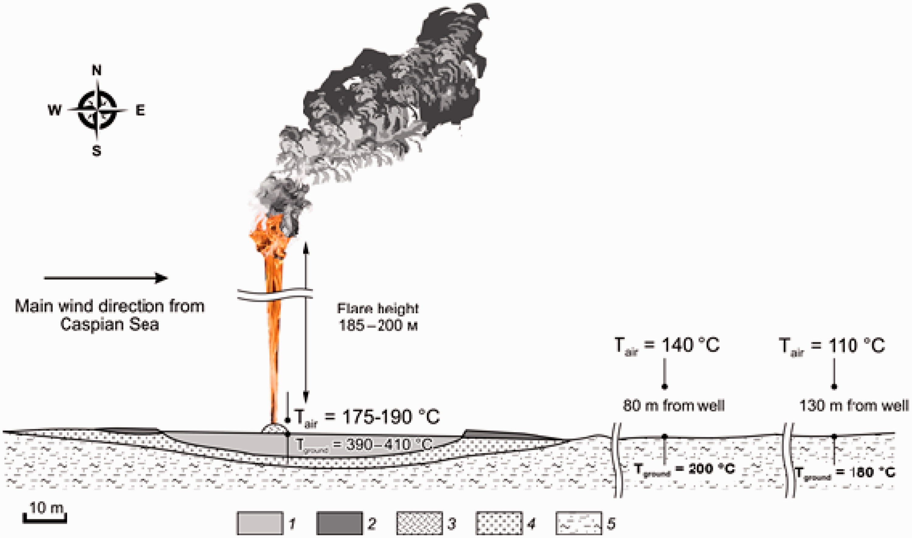
We failed to find clear indications of the melt quenching time, but the lake of silicate melt around the hole definitely had been quenched to glass by the time when a single vertical flare formed. Thus, the melt solidified in no more than five days.
The breakdown elimination took 400 days, and the fire at well 37 was extinguished as late as 27 July 1986 after placing stop valves and subsequent injection of drilling mud. The total amounts of combustion products released into the air over the whole ignition period were 3.4 × 10⁶ tons of oil and 1.7 × 10⁹ m3 of combustible gas (including 516 × 103 tons of Н2S and 850 tons of RSH or mercaptans), as well as 1.0 × 10⁶ tons of uncombusted hydrocarbons and 900 × 103 tons of soot (Potapov, 1994).
Thermal halo
For about two months, the oil–gas fire had produced a zoned thermal metamorphic halo (Figure 3), with silt sand and clayey silt molten fully in the hottest central zone and partially on the periphery. The protolith consisted mainly of quartz, calcite, illite, and anorthite and lesser amounts of gypsum, chlorite, and salt rock; the melting zone involved also numerous metal fragments of drilling tools. The silicate melt formed a large oval lake (52 × 75 m), elongate in the West–East direction along the main wind transport (Potapov, 1994). The lake apparently was 1.0 or 1.5 m deep (inferred by modeling no explicit evidence being available) and accommodated, respectively, 4000 or 6000 m3 of silicate melt. The amount of sedimentary material molten at the accident site was enormous on the scale of natural CM (Grapes, 2011; Sokol et al., 2005).
The melt column underwent extremely rapid quenching (especially on the lake surface) into variegated massive glasses called tengizites (Figure 3), while the partially molten thermally altered sediments (mesolites) made a 15- to 20-m wide fringe on the periphery of the tengizite lake (Potapov et al., 2001). The mesolite fringe rises 0.45 m over the subsided surface of the tengizite lake in the West and makes terraces rising to 1.5 m in the East. Unlike the massive tengizite, mesolite is a porous rock containing residual material (mainly quartz and less abundant feldspar) besides the newly formed glass crystals. The mesolite is related with the protolith sediments through gradual transitions.
Methods
The major- and trace-element compositions of minerals were analyzed in 25 samples of CM rocks and seven samples of fresh sediments around the tengizite lake. The mineralogy and petrology of the samples were studied at analytical laboratories of the Institute of Geology and Mineralogy (Novosibirsk) on LEO 420 SEM and JSM 6380LA scanning electron microscopes, a DRON-3 diffractometer, and Camebax-Micro and JXA-8100 microprobes, at 20 kV accelerating voltage, 15–30 nA beam current, 40° incident angle, 10 s count time at each analytical line, and a probe diameter of 2–3 µm. The estimates of all components were accurate to 2%; the detection limits of Cmin did not exceed 0.1–0.2 wt.%.
The water content in the glasses was estimated using a Bruker Vertex 70 IR spectrometer equipped with a Hyperon 2000 microscope. The spectra were obtained for 170 µm thick double-polished sections with a 70 µm aperture, to a resolution of 4 cm−1.
The CM samples were annealed and molten in a VTP-06 furnace. The samples were heated in alundum crucibles at ambient pressure at a rate of 120℃ per hour and then kept exposed to different temperatures for different residence times: 17 hours at T = 950℃, 12 hours at T = 1030℃ and 10 hours at T = 1100℃. Then the furnace was cooled down to 500℃ for 4 hours, with subsequent temperature decrease to 25℃ for 11 hours.
Results and discussion
Characteristic of tengizites and mesolithes
Major-element chemistry
Major-element composition (wt.%) of CM rocks produced by the Tengiz oil–gas fire.
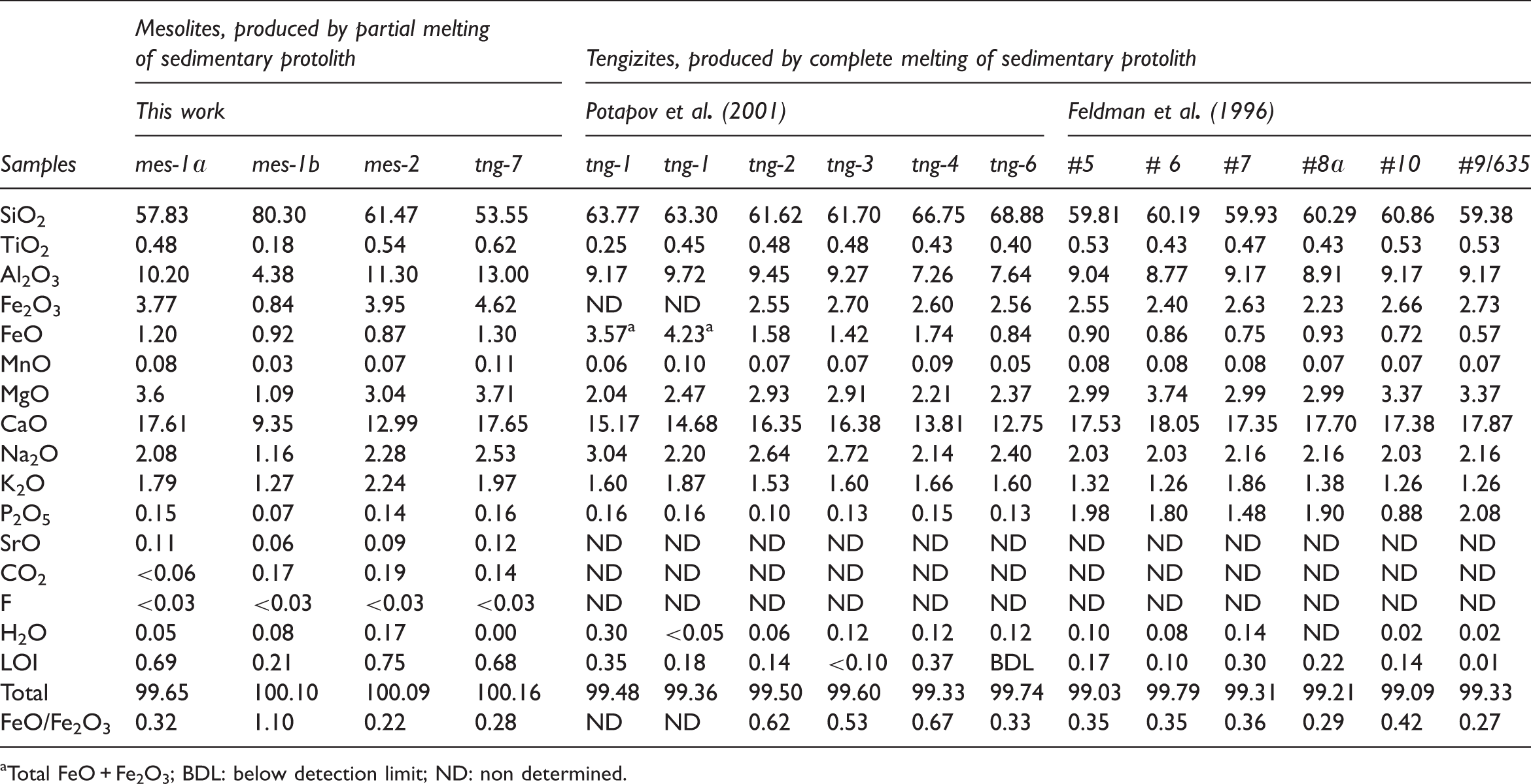
Total FeO + Fe2O3; BDL: below detection limit; ND: non determined.
Compared to tengizites, mesolites are more depleted in SiO2 (53.55–61.67 wt.%) but have higher enrichments of Al2O3 (10.20–13.00 wt.%), MgO (3.04–3.17 wt.%), K2O (1.79–2.24 wt.%), and TiO2 (0.48–0.62 wt.%); they also have lower FeO/Fe2O3 ratios (0.22–0.32) and a higher total of volatiles (0.68–0.75 wt.%), while H2O is within 0.17 wt.%, CO2 <0.19 wt.%, and S is in the range 0.09–0.14 wt.%. A single mesolite sample (mes-1b) has a very high SiO2 content of 80.30 wt.% and lower concentrations of other major oxides, possibly because of local quartz sandstone enrichment in the protolith.
Mineralogy and petrography
The tengizite glasses are dense, massive, with conchoidal fracture. Their light and dark blue varieties are rather opaque and often heavily striated (Figure 4a–e); the dark green, brown, and black varieties are translucent. The glasses lack any pores; sporadic gas vesicles (40–60 µm) were found in a few cases only. The tengizite samples collected on the surface are partly devitrified glasses remarkable by heterogeneous nucleation of Ca3Si3O9 and clinopyroxene modifications on linear and point defects leading to formation of spherical aggregates. The resulting spherolites (20–400 µm in diameter) composed of fibrous crystals are aggregated into particular 5-cm long and 0.1- to 5-mm thick streaks. Less often the minerals exists as single large (5 mm) spherolites (Figures 4c and d and 5a–c).
Products of combustion metamorphism of sand–clay protolith at well 37 site. (a–e) tengizites (massive variegated glasses) produced by complete melting of sedimentary protolith. Light and dark blue varieties are poorly transparent and most often heavily striated. Dark green, brown, and black glasses contain streaks and spherolites of fibrous Ca3Si3O9 crystals and clinopyroxene. (f) Mesolite produced by partial melting of sedimentary protolith, a light beige highly porous rock. Habits of minerals in CM rocks from thermal halo of Tengiz fire: tengizites (a–c) and mesolites (d–f). Photographs (a) and (b) are in polarized light, without analyzer; other photographs are backscattered electron images. (a, b) fibrous Ca3Si3O9 and diopside spherolites and streaks in high-silica glass; (c) particle of native Si enclosed between diopside hopper crystals and wollastonite needles; (d) quenched CM phases and remnant unassimilated quartz grains in mesolite; (e) tridymite stellate aggregates in high-silica glass and remnant quartz grains at the center of tridymite aggregates encircles with concentric cracks; (f) spear-shaped tridymites and wollastonite laths in high-silica glass. Abbreviations stand for names of minerals: Cpx = clinopyroxene (diopside); Gl = glass; Pl = plagioclase (labradorite-bytownite); Qz = quartz; Trd = tridymite; Wo = wollastonite (1T). CM: combustion metamorphism.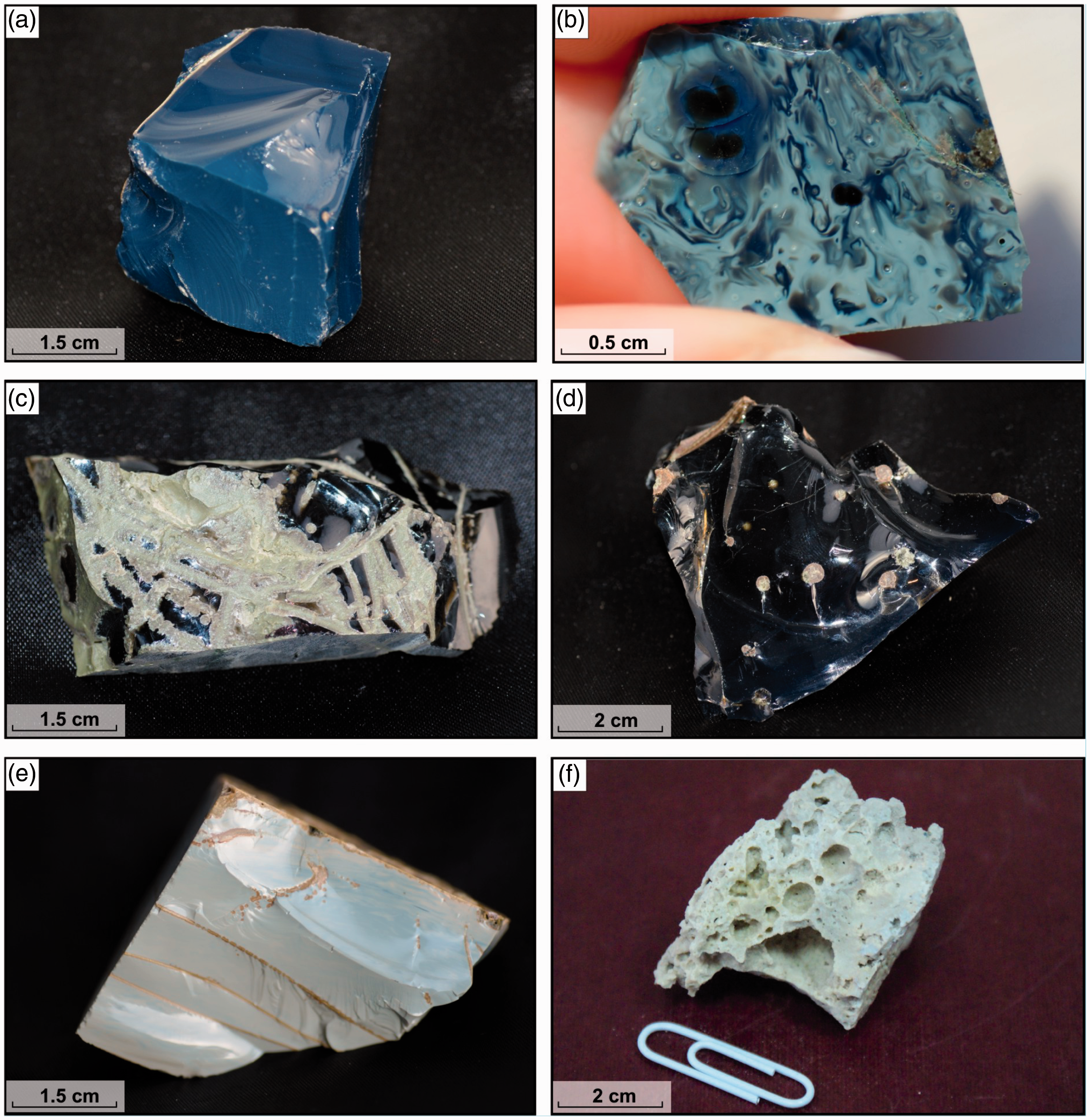
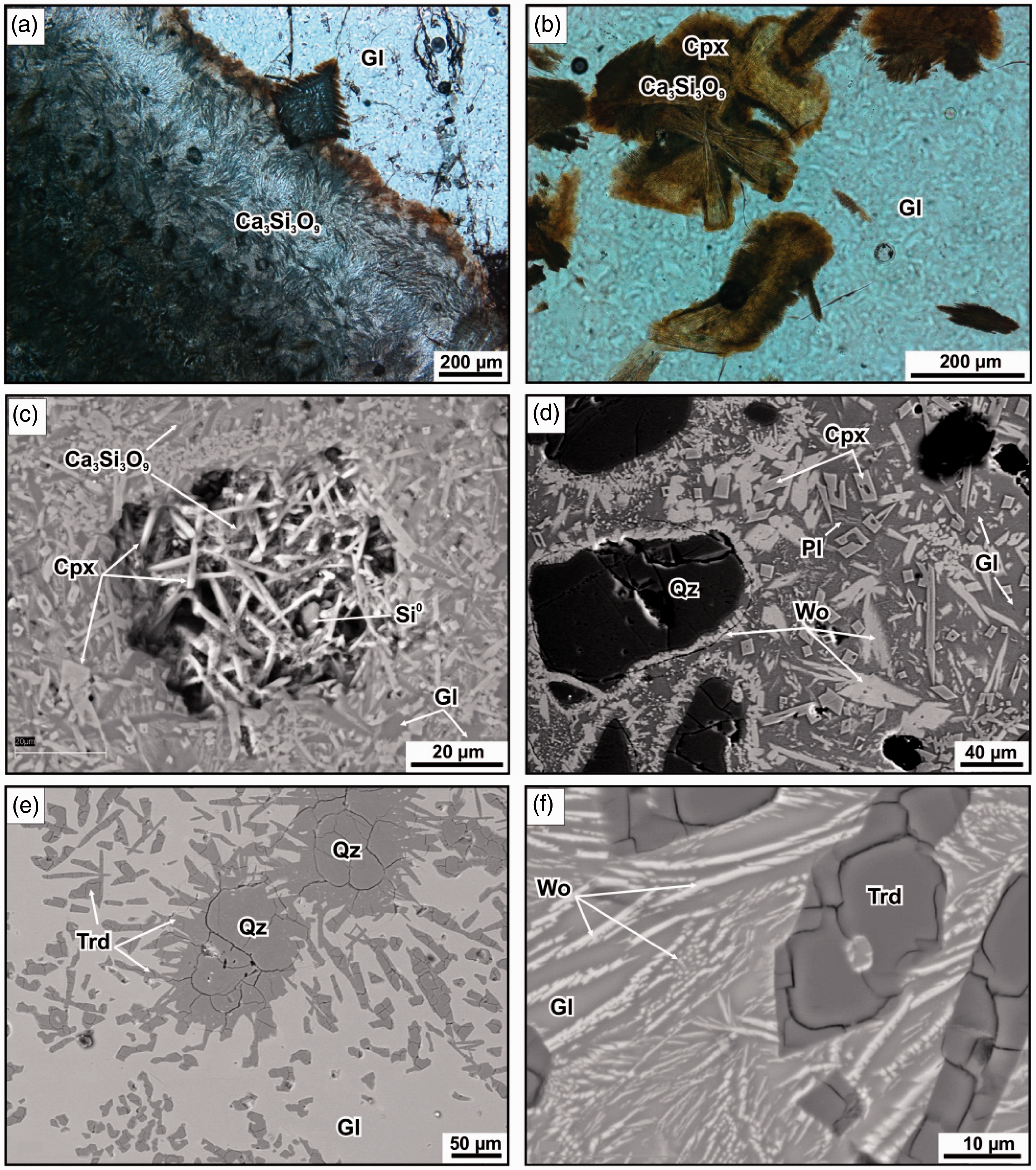
The CM minerals in mesolites are much coarser, often euhedral, and show a morphology of quench phases (Figure 5d–f). They are most often hopper-like, acicular (5–40 µm), and anhedral (30–250 µm) diopsides or spherolitic fibrous aggregates. Large crystals show well-pronounced growth zoning with colors changing from opal to dark green. Wollastonite (1T-Ca3Si3O9) exists as laths or less often as platy or hopper-like crystals up to 70 µm. The presence of parawollastonite (2 M polytype) and pseudowollastonite in mesolite samples was not identified optically but detected by X-ray powder diffraction. Plagioclase occurs as 15- to 30-µm long laths or 2- to 5-µm acicular crystals.
In the sample mes-1b, tridymite growing immediately from the melt is the most abundant new phase. It occurs as stellate aggregates (150–400 µm), spear-shaped crystals or irregularly shaped segregations (5–120 µm) set in silica glass (Figure 5e and f). The stellate aggregates enclose remnant quartz grains surrounded by concentric cracks produced by expansion during polymorphic transformation of quartz into metastable crystobalite (detected by XRD) prior to tridymite crystallization (Gramenitsky et al., 2000; Grapes, 2011). The spear-shaped tridymites enclose glass and are cracked, with heterogeneous nucleation of ultrafine wollastonite laths on their surfaces.
The mesolite glasses can be optically homogeneous or bear products of partial devitrification (plagioclase and wollastonite microcrystals). Viewed under polarized light in thin sections, the glasses vary from transparent colorless to translucent brown varieties. Both mesolites and tengizites lack opaque ore minerals, including separate iron minerals.
Chemistry of minerals and glasses
Representative compositions of rock-forming minerals in mesolites (wt.%).
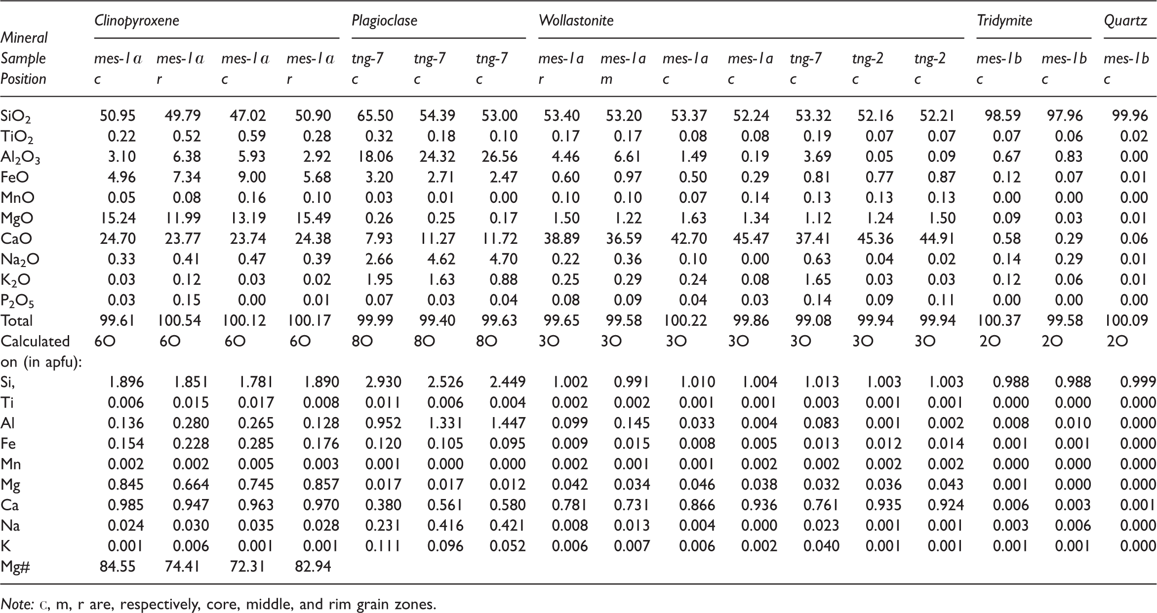
Note: с, m, r are, respectively, core, middle, and rim grain zones.
EMPA results of satisfactory quality were obtained only for wollastonite (1T) out of three Ca3Si3O9 modifications identified in mesolites. It consists of almost invariable SiO2 (52.16–53.40 wt.%) and CaO ranging broadly from 36.59 to 45.91 wt.%, with minor Al2O3 (0.09–6.61 wt.%), MgO (1.12–1.63 wt.%), FeO (0.29–0.97 wt.%), and MnO to 0.14 wt.% (Table 2). The empirical formula of wollastonite includes the impurities Ca0.73–0.94Al0.00–0.14Mg0.03–0.05Fe0.00–0.02Si0.99–1.01O3 incorporated into the mineral during its extremely rapid crystallization from melts of complex compositions, which is known to be an unwanted effect in production of refractory materials (Grapes, 2011; Seryotkin et al., 2012).
Plagioclases are most often of labradoritic composition (An50–58Ab32–40Or5–15), and a few laths are bytownitic (An82Ab14Or4). Their common impurities are 2.47–3.20 wt.% FeO, 0.10–0.32 wt.% TiO2, and 0.17–0.26 wt.% MgO (Table 2).
Mesolites and tengizites contain three SiO2 polymorphic modifications, which are mostly tridymite or less often crystobalite and unassimilated quartz grains. The presence of tridymite and crystobalite has been confirmed by XRD. Tridymite is easily spotted against other silica modifications due to its morphology, chemistry, and violet fluorescence (unlike yellow fluorescent quartz). Like many CM tridymites (Cosca et al., 1989; Grapes, 2011; Sokol et al., 2005), it has significant contents of impurity oxides besides silica (0.83 wt.% Al2O3, 0.58 wt.% CaO, 0.29 wt.% Na2O, 0.12 wt.% K2O, and 0.12 wt.% FeO) and, correspondingly, lower SiO2 of 97.96–98.59 wt.% (Table 2); detrital quartz is pure SiO2. The quality of EMPA data for crystobalite was insufficient.
Grains of native Si (Si0), 5 µm, were found and identified by SEM in tengizite samples, in closed pores between diopside hopper crystals and wollastonite needles (Figure 5c).
Representative and average compositions of glasses in mesolites and tengizites (wt.%).
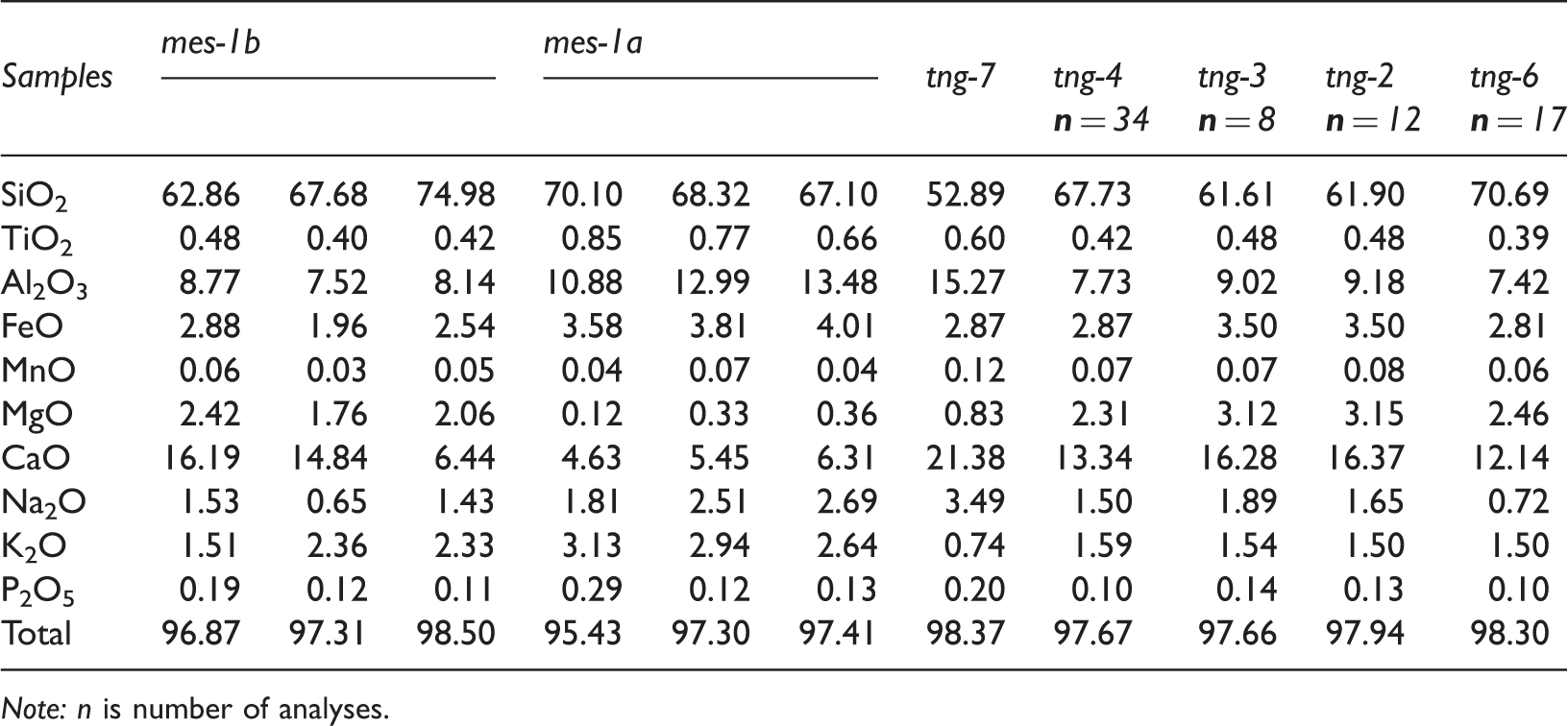
Note: n is number of analyses.
Unlike the compositionally uniform tengizite glasses, the Al–Ca glasses in mesolites differ in their chemistry between and within the samples. They show greater Si, Al, K enrichments and are more depleted in Mg and Ca relative to the whole-rock contents in the samples with diopside, wollastonite, and plagioclase being new CM phases: 68.32–70.10 wt.% SiO2, 10.88–13.48 wt.% Al2O3, 3.58–4.01 wt.% FeO, 0.12–0.36 wt.% MgO, 4.63–6.31 wt.% CaO, 1.81–2.69 wt.% Na2O, and 2.64–3.13 wt.% K2O. Glasses from the sample mes-1b tridymitic mesolite sample are lower in SiO2 (62.86–74.98 wt.%) but higher in Al2O3 (7.52–8.77 wt.%), MgO (1.76–2.42 wt.%), and CaO (6.44–16.19 wt.%) relative to the bulk rock compositions (Table 3).
Thermal metamorphism of sediments: Models
Main parameters in Tengiz fire models of gas and oil–gas flares of different geometries.
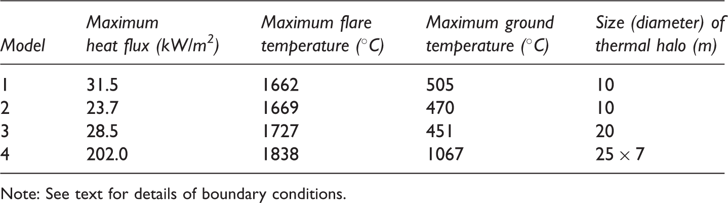
Note: See text for details of boundary conditions.
The temperatures and oxygen fugacity reached extremely high values at certain points in the immediate fire vicinity. Finds of native Si in a few isolated voids in tengizites have implications for gas bubbling and subsequent cooling of the melt. In industry, Si and SiC are synthesized from SiO2 in a carbothermal reduction process (Cetinkaya and Eroglu, 2011; Pokorná et al., 2008) with thermal cracking of methane at Tmin = 1400℃. Native Si forms by chemical vapor deposition in the reaction
Mesolites on the periphery of the molten lake consist of compositionally heterogeneous glasses, contain abundant unassimilated quartz particles, are structurally heterogeneous, and vary strongly in the size and geometry pores, i.e., no complete homogenization of rock structure and coalescence of pores have been achieved. Thus, metamorphic sediments on the periphery of the area existed in liquid plastic state but have not been fully molten. None of the tengizite or mesolite samples exposed to experimental annealing (for 10 hours) showed partial melting at 1100℃, i.e., the liquidus of the system is above this temperature. The presence of pseudowollastonite in mesolite indicates that the melts reached 1220℃ (Seryotkin et al. 2012). By analogy with production of silica bricks, abundant tridymite in mesolites may record prolonged heating of the protolith at 1000℃ or more (Gramenitsky et al., 2000). This inference is consistent with regular presence of crystobalite which appears in the metastable form in the range from 850–900℃ to 1150–1200℃ prior to the α-quartz → tridymite transition (Grapes et al., 2013; Schairer and Yagi, 1952). Note that crystallization of crystobalite in its stability field (T = 1470℃ at 1 bar) has never been observed so far in CM systems (Bentor et al., 1981; Cosca et al., 1989; Grapes, 2011; Grapes et al., 2013; Sokol et al., 2005). The morphology of rock-forming mesolite minerals indicates extremely rapid quenching rates (Figure 5).
Thermal effects of the Tengiz fire on the country rocks
The parameters of thermal metamorphism have been estimated by simulating the thermal effect of the Tengiz fire on the ground surface. A gusher of combustible gas with oil droplets is assumed to blow out from the well and burn in the air, while the total (radiative and convective) heat flux from the flare heats up the rocks around the well. Processes of this kind can be simulated employing the models of turbulent flow, turbulent gas-phase combustion, motion and combustion of oil droplets, radiative heat transfer, and conductive heat transfer in soil.
The turbulent flow of gas was simulated by solving Reynolds-averaged Navier–Stokes (RANS) equations using the two-equation turbulence model, the version called Menter shear-stress transport (MSST) turbulence model (Menter, 1993). For turbulent gas-phase combustion, we chose a hybrid model, with the rate of the fuel-oxidizer reaction calculated on the basis of the multistage reaction mechanism and the method allowing for the rate of turbulent gas mixing. The reaction mechanism was presented as four global mechanisms of Jones and Lindstedt JL-1 (Kim et al., 2008). When simulating the motion and evaporation of oil droplets, we used the Lagrange method of tracking individual particles, taking into account the heat and mass transfer between the droplet and the ambient gas (Dekterev et al., 2010). The radiative heat transfer was modeled with the discrete ordinate method. The gas absorption coefficient was found using the weighted-sum-of-gray-gases-model (WSGGM) (Litvintsev and Dekterev, 2008). The system of differential equations for mass, momentum, and energy transfer, as well as for turbulence parameters, was discretized using the finite-volume method (Patankar, 1991). The convection and diffusion terms in the equations were approximated by second-order accurate schemes. The cited methods were implemented with the SigmaFlow software designed jointly by teams from the S.S. Kutateladze Institute of Thermophysics and the Department of Thermophysics of the Siberian Federal University (Kamenschikov et al., 1995). The software was tested on a broad scope of problems in aerodynamics, heat and mass transfer, and combustion (Dekterev et al., 2010).
The Tengiz event was simulated using the abovementioned mathematical modeling and unstructured grids consisting of more than 500 polygonal 3D elements (Table 4).
Simulation began with the simplest case of a straight-flow vertical gas flare (Model 1, Figure 6), with the following boundary conditions: combustible gas (100% CH4) flows into the air from a well casing pipe 0.4 m in diameter; the flame rises from a height of 0.5 m above the ground surface (pipe stickup); gas flows at a rate of 15 kg/s; the temperature of both gas and ambient air is 25℃; the ground temperature at the 30 m depth is 5℃. As combustible gas blows out toward the flare root, it mixes up with the ambient air while the latter becomes subject to ejection. As a result of high flow rate, the flare rises off the pipe and ignition occurs 3–4 m above it. The high-temperature flare core (above 1400℃) spreads at the height from 5 m to 90 m. The flare of this geometry can heat up a round spot (10 m in diameter) on the surface to 500℃ (Figure 6c and d), and the thermal effect can penetrate to 5 m below the surface (Figure 6b). The flare with these parameters is obviously unable to maintain thermal metamorphism like that observed at the Tengiz site.
Model 1: Single straight vertical gas flare. (a) Problem formulation; (b) temperature field in central vertical flare section (℃); (c) color-coded isothermal surfaces in flare: green, yellow, and red colors correspond to temperatures of 600℃, 1000℃, and 1400℃, respectively, and ground temperatures (℃); (d) temperature field on ground surface (℃).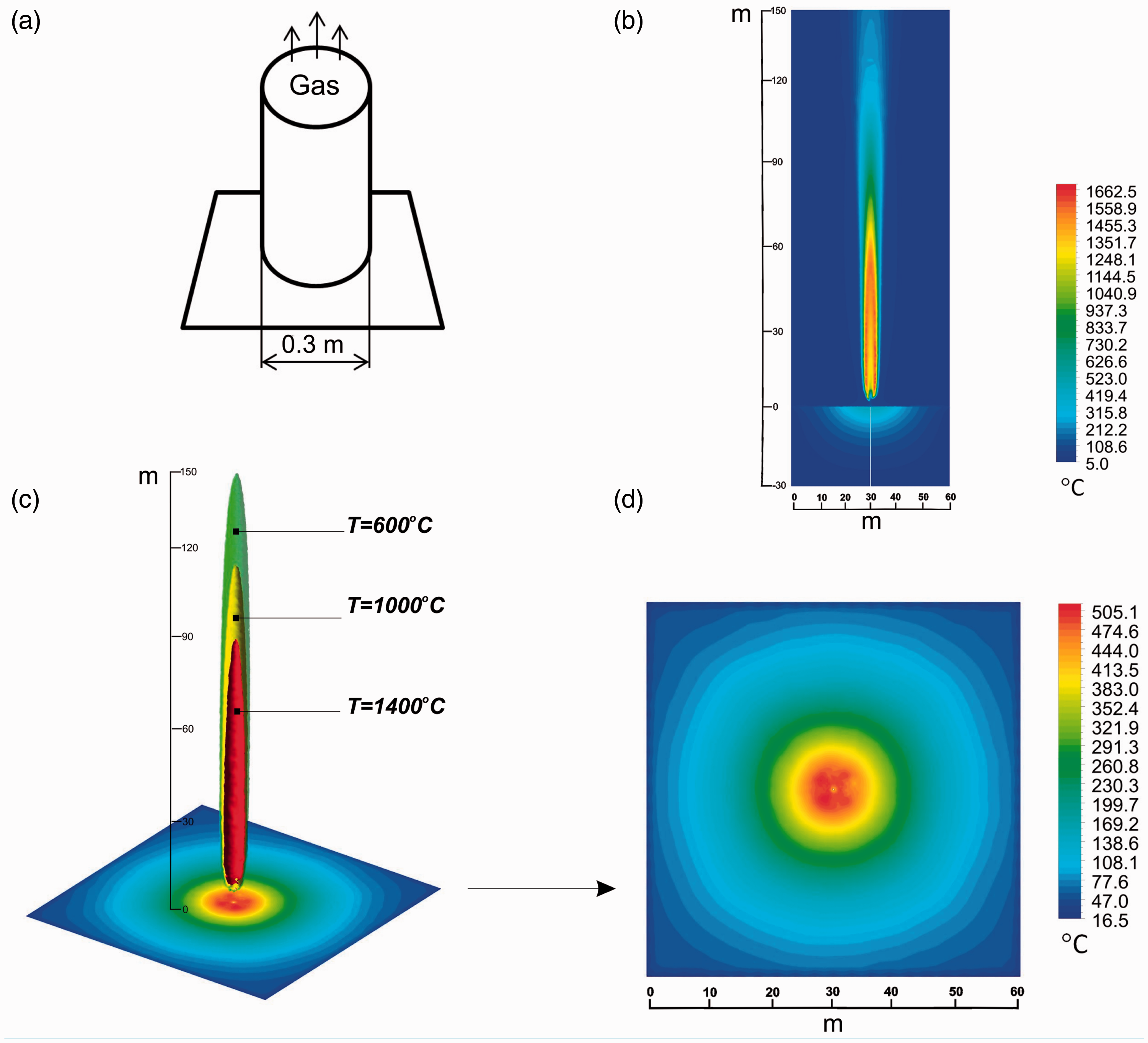
In Model 2 (Figure 7), the combustible gas had a composition similar to the real case (70 vol.% methane and 30 vol.% oil), the gas and oil flow rates being 15 kg/s and 10 kg/s, respectively. Other physical and geometrical parameters of the flare were same as in Model 1. Such a flare existed at well 37 from 10 September 1985 to 27 September 1986. As modeling predicts, the hottest zone of >1400℃ of this flare must be as high as 110 m. However, this difference from the Model 1 results causes no significant change to the thermal effect it can produce (Figure 7c and d).
Model 2: Single straight oil–gas flare. (a) Problem formulation; (b) temperature field in central vertical flare section (℃); (c) color-coded isothermal surfaces in flare: green, yellow, and red colors correspond to temperatures of 600℃, 1000℃, and 1400℃, respectively, and ground temperatures (℃); (d) temperature field on ground surface (℃).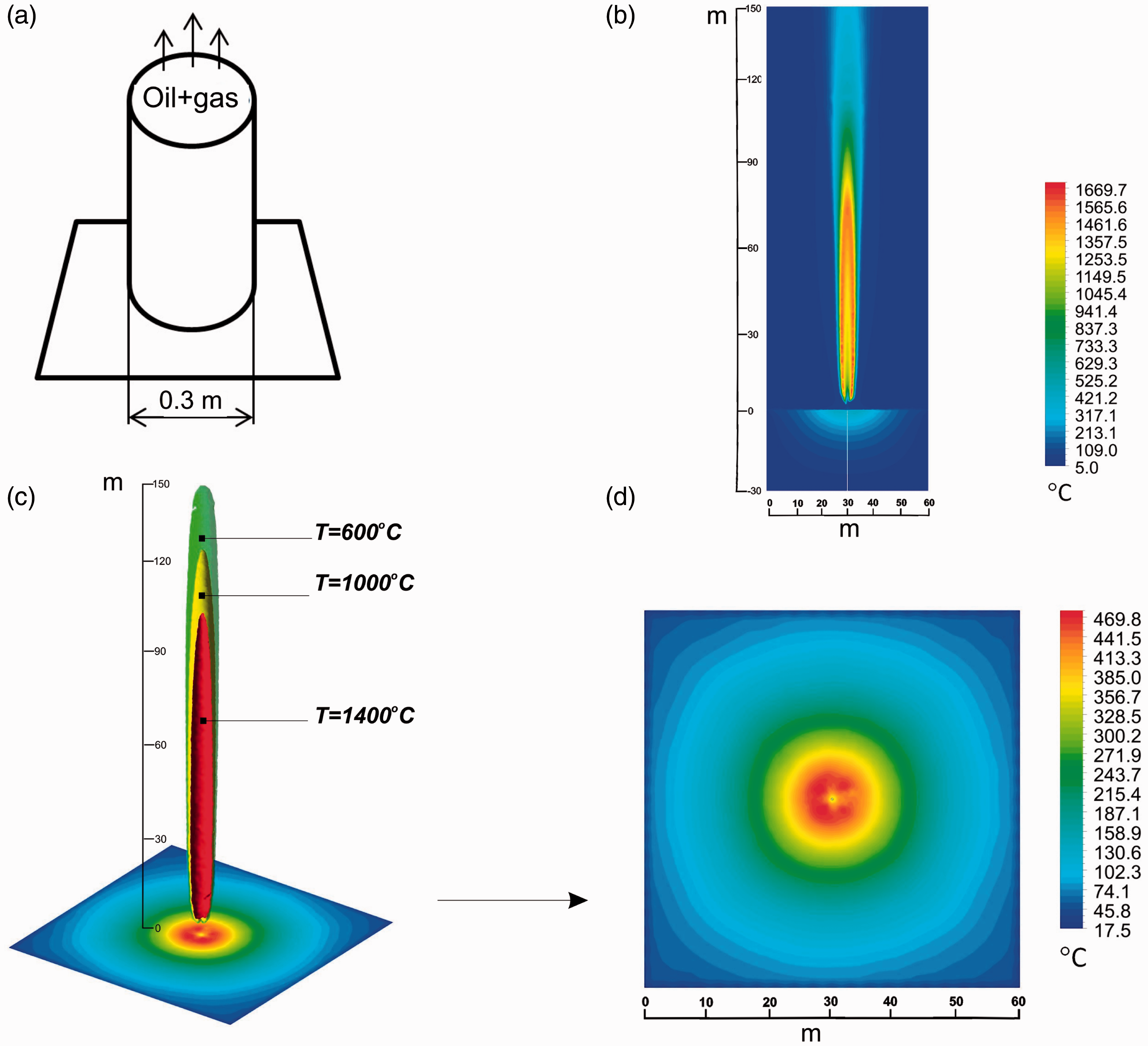
Model 3 represented a single oil–gas flare exposed to lateral wind load (Figure 8), and the boundary conditions were as in Model 2. The model accounted for the effect of lateral wind common to the area, with its speed assumed to be 10 m/s.
Model 3: Single straight oil–gas flare, with lateral wind load. (a) Problem formulation; (b) temperature field in central vertical flare section (℃; (c) color-coded isothermal surfaces in flare: green, yellow, and red colors correspond to temperatures of 600℃, 1000℃, and 1400℃, respectively, and ground temperatures (℃); (d) temperature field on ground surface (℃).
In these conditions, the flare deflects from the vertical to 45°. The hot zone is twice larger (20 m in diameter instead of 10 m in the previous models), but the highest temperature on the surface does not exceed 450℃ (Figure 8c).
Model 4 simulated a composite oil–gas flare with three spouts of different directions: one vertical and two horizontal ones (Figure 9). A flare with these parameters existed at well 37 in the beginning of the accident (from 26 June 1985 to 05 September 1986), when it produced a lake of silicate melt. The boundary conditions of the model were: 0.4 and 0.2 m diameters of the vertical and horizontal casing pipes, respectively; 70 vol.% methane plus 30 vol.% oil in the combustible mixture; 15 kg/s and 10 kg/s gas and oil flow rates, respectively; 25℃ ambient temperature; 5℃ ground temperature at 30 m below the surface; 0.5 m pipe stickup. A flare of such geometry and composition can provide the highest heat flux on the surface and heat up the surface to 800–1070℃ in 25 × 7 m zones immediately beneath the horizontal spouts (Figure 9c).
Model 4: Composite oil–gas flare consisting of three spouts oriented in different directions. (a) Problem formulation; (b) temperature field in central vertical flare section (℃); (c) color-coded isothermal surfaces in flare: green, yellow, and red colors correspond to temperatures of 600℃, 1000℃, and 1400℃, respectively, and ground temperatures (℃); (d) temperature field on ground surface (℃).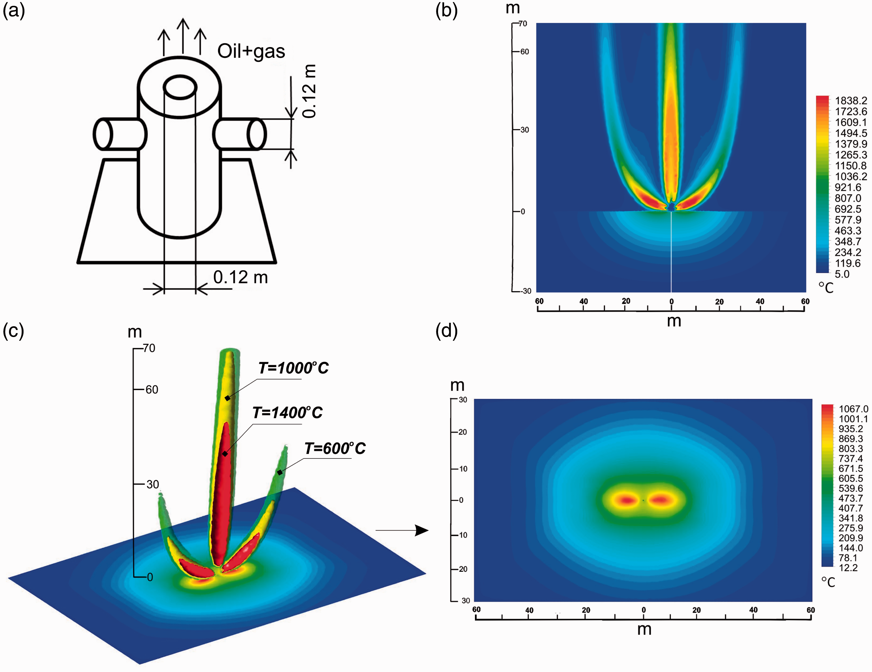
Conclusions
The oil–gas fire at the Tengiz oilfield and its thermal effect on the country rocks were simulated using the SigmaFlow software. The models took into account the spatial turbulent airflow mechanics of the flare, convective, and radiative heat transfer, combustion of gas and oil droplets, as well as conductive heat in soil. The thermal effect on rocks was simulated for a straight-flow flare with different compositions of the combustible mixture, directions, and geometries of the flame, and with invariable values of casing pipe diameter, gas and oil flow rates, and pipe stickup (blowout point).
The real parameters of the emergency case and the reconstructed conditions of thermal metamorphism of sediments (tengizite and mesolite, produced by complete and partial melting of the sand–clay protolith) were used to generate four thermophysical models of gas and oil–gas flares. Namely, Model 1 of a single straight vertical gas flare (100% CH4), Model 2 of a single straight vertical gas flare with 70% CH4 + 30% oil, Model 3 of a single straight vertical gas flare with lateral wind load and 70% CH4 + 30% oil, and Model 4 of three spouts of different directions (70% CH4 + 30% oil).
Model 4 simulates the best the Tengiz fire in the period from 26 June 1985 to 05 September 1986. As the model predicts, a flare with the parameters as in that of Tengiz can cause partial melting of sedimentary material in a local zone and thus produce mesolites (at 1100℃). An oil–gas flare of this kind, with the flame blowing out above the surface, can provide significant heat flux to the ground surface only in the presence of a large horizontal component, but the heated rocks are reduced to the zone immediately below the flare (≤25 m in diameter in our case). The models with a combustible mixture of oil droplets plus methane give a different geometry of isothermal surfaces inside the flare but the same temperature of sub-flare rocks (Figures 6 and 7). Therefore, bulk melting of thermally altered sediments (1200–1400℃) was impossible with such flare alone and required additional heating, which may have been due to ignition of oil flows spilled over the surface.
The reported models of the Tengiz fire demonstrate that a single vertical flare from a pipe with a 0.5-m stickup can heat up the rocks beneath it to no more than 500℃ (Figures 6 and 7) and is insufficient for the T = 1000–1400℃ CM of rocks.
We infer preliminarily that natural high-temperature CM foci genetically related with combustion of hydrocarbon gases most likely owe their origin to subsurface ignition. This inference agrees with observations reported from mud volcanoes in Azerbaidjan where the rocks in the fractured zone of methane combustion were the hottest at the depth of 10–12 m (Kovalevsky, 1940), as well as with the 7–12 m depths (relative to the present surface) of ultrahigh-temperature Ca paralavas in Nabi Musa fossil mud volcano (Sokol et al., 2010; Sokol et al., 2012). Further modeling of natural CM systems has to take into account fractures in rocks around the blowout point. In this case, the flare can burn continuously and some part of the fuel can burn in subsurface fractured zones.
Footnotes
Acknowledgments
We wish to thank K.A. Kokh, I. Kupriyanov, and E.N. Nigmatulina (IGM, Novosibirsk) for assistance in experimental and analytical work.
Declaration of conflicting interests
The author(s) declared no conflicts of interests with respect to the research, authorship, and/or publication of this article.
Funding
The author(s) disclosed receipt of the following financial support for the research, authorship, and/or publication of this article: The study was supported by grant MK-5754.2012.5 from the President of the Russian Federation and Integration Project #1-2013 SB RAS-NAS of the Ukraine.