
Abstract
A holistic fault detection and diagnostics (FDD) method should explicitly consider the dependencies between faults at the system- and zone-level to isolate the root cause. A system-level fault can trigger false alarms at the zone-level, while concealing the presence of a zone-level fault. However, most FDD methods have focused on a single component/equipment without considering the importance of the interactions between zone- and system-level devices. This paper proposes a holistic hierarchical framework for FDD, combining the process of detection and diagnosis of controls hardware and sequencing logic faults affecting the actuators at the system- and zone-level. The proposed framework follows a holistic sequential procedure to diagnose faults and suppress false alarms in this order: hard faults in air handling units (AHUs), hard faults in variable air volume (VAV) zones, sequencing logic faults in AHUs, and sequencing logic faults in VAV zones. The detection of faults is performed by visualizing the discrepancies between the expected and measured operational behaviour of AHUs and VAV boxes. Examples demonstrating the framework are provided with data from 10 different VAV AHU systems.
Keywords
Introduction
Heating, ventilation, and air conditioning (HVAC) systems provide comfort by adding or removing heat, moisture and supplying properly filtered air to spaces and are one of the main energy consumers in commercial and institutional buildings. HVAC controls are implemented by building automation systems (BASs) to manage energy and comfort. While improvements in sensing, communication, and control infrastructure introduced data-driven opportunities to improve building operation, an increase in the number of devices in HVAC control systems and the complexity of modern sequences of operation have increased the likelihood of faults. 1 These faults can emerge during the installation, operation, commissioning, and maintenance of the HVAC systems. 2 Therefore, timely diagnosis and correction of these faults can considerably reduce commercial buildings’ energy waste, increase the lifespan of HVAC equipment and provide a comfortable, healthy, and productive indoor environment. 3 In order to achieve this objective, FDD methods have been developed to address the issue by identifying faults’ incidence and isolating their root cause. 4
A multiple zone VAV AHU system is the most common HVAC configuration in commercial buildings in North America In general, faults in multiple zone VAV AHU systems can be soft faults such as inappropriate setpoints, modes and states of operation arising from incomplete or poorly written sequences of operation by engineers, wrong interpretation of sequencing logic, and tuning control loop mistakes by BAS operators, or hard faults due to the physical failure of devices such as sensors, actuators, and equipment. 5 The majority of the previous research on FDD for AHUs and VAV thermal zones has addressed hard faults in the way that researchers have taken a single component/equipment approach and proposed FDD methods for one category, such as AHU/VAV actuators, AHU sensors, etc.6–9 A few studies focused on soft faults, while sequencing logic faults or programming errors occur more often in the VAV AHU systems. In addition, most of the methods did not take an all-inclusive approach that looks at both sequencing logic and hard faults, considering zone-to-system interactions to isolate their root causes. For example, poor economizer programming causes an anomaly in outdoor air damper performance; however, a proposed FDD model that is able to detect the faulty damper may not be able to differentiate whether it is a stuck/broken/leaky damper or there is an AHU sequencing logic fault causing the anomalous damper behaviour. Additionally, a zone-level hard fault such as a stuck/broken/leaky VAV damper can negatively affect the duct static pressure setpoint reset, which may incorrectly appear as an AHU sequencing logic fault. Similarly, a zone with a stuck/broken/leaky perimeter heater valve impacts the AHU modes of operation by triggering set-up or set-back modes due to zones violating their unoccupied cooling or heating temperature setpoints. Therefore, the presence of a perimeter valve actuator fault may conceal a faulty AHU mode of operation logic.
This paper combines hard and sequencing logic faults affecting the actuators of multiple zone VAV AHU systems in an FDD framework. The framework is designed by explicitly considering hierarchical dependencies between zone- and system-level hard and soft faults. This holistic framework not only detects the faults but also considers the importance of the hierarchical zone-to-system interactions for the diagnosis of the faults’ root causes. The main purpose of this paper is to develop a sequential framework to avoid false alarms caused by some other faults and to ensure a correct diagnosis of a fault in a component only after all hardware and software affecting that component are free from fault.
In the remainder of the paper, the prior studies on hard and sequencing logic faults and hierarchical dependencies between faults and fault detectability are reviewed to identify research gaps. Then a holistic framework is defined, and how the framework should be used is explained. Finally, the authors demonstrate the framework’s fault categories with illustrative examples from different buildings.
Background and previous work on FDD for VAV AHU system actuators
FDD for building HVAC systems has been a field of interest for academics for over 30 years. 6 As revealed by Katipamula and Brambley, 10 researchers have developed FDD methods in three main categories: qualitative (i.e. expert rules), quantitative (i.e. physics-based models), and process history-based (i.e. black- and grey-box models). One of the most popular and widely used sets of expert FDD rules defined for AHUs and single duct VAV boxes with hydronic reheat coils are the air handling unit performance assessment rules (APAR) and VAV performance assessment control charts (VPACC), respectively. 11 A similar set of rules are also incorporated in ASHRAE Guideline 36. 12 A fault alarm is generated with these expert FDD rules when the residuals representing the difference between expected and measured operational behaviour exceed expert-defined thresholds. 13 However, although expert rules require no training data and are easy to utilize, they are often unable to provide the root cause of the faults as there are several possible diagnoses for a specific rule. 14 In addition, when several rule thresholds are simultaneously exceeded, the list of possible diagnoses expands, and it is unclear what the actual fault is or whether there are indeed multiple faults. 14 Moreover, it is complicated to formulate expert rules that are comprehensive enough to consider all zone-to-system-level interactions.
Physics-based models rely on fundamental physical relationships and employ building performance simulation tools such as EnergyPlus and TRNSYS. A number of system quantities are measured and then compared to the predicted values. The deviation between measured and predicted model data sets is an indication of fault existence. 15
The grey- and black-box models are data-driven models that employ data inherent in BAS gathered by sensors, actuators, and meters to predict the system’s characteristics. The discrepancy between the predicted and measured model parameters of a system is an indication of fault occurrence. 16 If developed in recognition of zone-to-system-level interactions, models can enable researchers to derive more robust FDD rulesets. Black-box or grey-box models assimilate data in a way that human minds cannot do through their intuition alone. Then, researchers utilize these models to derive better rules.
All these FDD methods have been deployed to detect and diagnose both hard and sequencing logic anomalies in the AHUs and VAV zones. Thus, the literature review is divided into three parts. First, the papers that developed FDD methods for the actuator hard faults such as stuck/broken/leaking valve/damper in the AHUs and VAV thermal zones are discussed. Then, the papers with a focus on sequencing logic faults that impact the actuators' behaviour at the system- and zone-level are reviewed. Finally, the papers focusing on hierarchical dependencies between hard and soft faults at the system-and zone-level and their impact on fault detectability are reviewed.
FDD for hard faults
Hard actuator faults in AHUs and VAV zones are physical deficiencies associated with dampers and valves. These faults are identified as stuck/broken/leaking mixing box dampers, heating/cooling coil valves, VAV dampers, reheat coil valves, and perimeter heater valves. Most of the FDD methods have addressed hard faults in AHUs, yet still less amount of work has been done on the faults at the zone-level. For example, Gunay et al. 16 proposed an inverse grey-box model to detect and isolate zone-level sensor and actuator faults in an academic office building. They formulated a simple thermal network model to predict the rate of change in indoor temperature in which the parameters were estimated using a genetic algorithm. The anomaly of estimated model parameters was treated as an indication of the presence of sensor/actuator faults. They also conducted a point-by-point survey in the offices to inspect the physical condition of the actuators and sensors to validate the model. Most of the faults verified in the condition survey were in agreement with the anomalies identified by the model.
Basarkar et al. 6 generated detailed fault models for room temperature sensor offset, fouled heating coil, and leaking outdoor air damper and added the fault models to a developmental version of EnergyPlus to identify, characterize and prioritize the faults. The results showed that the occurrence of these faults could increase the total HVAC energy use by as much as 22%. Dey and Dong 14 employed Bayesian Belief Network models as a diagnostic tool. They combined it with APAR rules to diagnose the best possible root cause when one rule is satisfied. The tool was also able to prioritize faults when conditions for multiple rules were satisfied simultaneously. They applied their model on an AHU for the cooling state. They were able to detect and diagnose temperature sensor biases, heating/cooling coil fouling, mixing box dampers, and heating/cooling coil valve stuck/leakage. Zhao et al. 17 developed a diagnostic Bayesian networks (DBNs) – based model to diagnose 28 faults which cover most of the common hard faults in fans, dampers, ducts, filters, and sensors of an AHU. They developed four DBNs models based on a complete survey of FDD methods on AHUs reported in three projects, including the National Institute of Standards and Technology (NIST) 6964 18 and ASHRAE research projects 1020 19 and 1312. 20 They evaluated the models with experimental data and concluded that the DBNs are able to detect and isolate the faults such as outdoor/return/exhaust damper stuck, return fan fixed speed, duct leaking, and filter fault.
Gunay and Shi 5 proposed a cluster analysis method that merges the BAS data into a small number of different operation patterns. The patterns are intended to help energy managers identify and interpret faults through visualization. Their suggested clustering algorithm identified anomalies associated with VAV damper, airflow sensor, and perimeter heater’s valve at the zone-level and return/outdoor air damper at the system-level; however, they did not identify the root cause of these anomalies. McHugh et al. 7 analyzed 10 different data-driven algorithms to find which one is more effective in identifying heating/cooling valve leakage in AHUs. Among the analyzed models, the decision tree model achieved the most desired characteristics: fewer features, speed in detection, novelty identification, etc., while maintaining high prediction accuracy. Torabi et al. 8 developed three process history-based models to investigate the fault detectability of actuators in AHUs in the absence of intermediate temperature sensors. Their results indicated that the generated algorithms could act as virtual sensors to predict intermediate temperatures essential to isolate hard faults in the AHUs outdoor air damper and heating/cooling coil valves. The models were able to discover faults such as a broken heating coil valve and a leaky outdoor air damper.
FDD for sequencing logic faults
An AHU is used to control supply air temperature, humidity, and supply and outdoor airflow. The temperature is controlled using heating/cooling coil valves to maintain the supply air temperature setpoint. The total airflow is controlled through supply/return fan variable frequency drive (VFD) to maintain a duct static pressure setpoint. The outdoor airflow rate is controlled via mixing box dampers modulating in tandem with the fan VFDs to maintain ventilation requirements of indoor air quality standards, including ASHRAE 62.1. 21 At the zone-level, the temperature is controlled by modulating the VAV reheat coil and/or perimeter heater valve along with the VAV airflow rate; and the airflow is controlled by regulating the VAV damper to maintain the airflow setpoint. The sequencing logic that controls humidity is not discussed in this paper. Therefore, the sequencing logic defined by engineers and implemented by control integrators into the BAS system governs an actuator’s performance. Consequently, an inappropriate sequencing logic results in a faulty actuator operation. In this section, the papers with a focus on sequencing logic faults that impact actuator performance at both system- and zone-levels are reviewed.
For instance, in the cluster analysis-based anomaly detection method that Gunay and Shi 5 proposed, they detected a logic mistake in supply air temperature setpoint reset that caused an AHU to operate in the economizer state while nearly all perimeter heaters were in use. This energy-wasting fault caused the outdoor air damper and most perimeter heater valves to remain fully open and the heat recovery wheel to remain off during most of the winter. Doty 22 analyzed simultaneous heating and cooling as a common sequencing logic mistake that is caused by improper modulation of heating and cooling coil valves. Simultaneous economizer and heating and simultaneous economizer (when the outdoor air damper is between minimum and 100% position) and mechanical cooling are also sequencing logic faults that result in inappropriate behaviour of outdoor air dampers 23 For example, Schein 24 performed a field study on-site where APAR and VPACC were embedded in AHU and VAV box controllers. One of the AHU’s controllers under his study generated a fault with a possible controller tuning or logic error diagnosis. A review of the control logic revealed that the output of the temperature control proportional integral derivative (PID) loop was sent to the cooling coil valve and outdoor air damper simultaneously, which consequently leads to a chiller load and run-time increase. Also, the generated data-driven models by Torabi et al. 8 detected an anomaly in the operation of the outdoor air damper beyond the minimum position setpoint while the heating coil valve was still operational. The line of code in the BAS program causing this error was removed, which ended up addressing this fault.
Inappropriate AHU modes of operation is another common sequencing logic fault that has an impact on a number of actuators at the system- and zone-level. In other words, if an AHU does not follow the operating schedule or has a more extended than required warm-up/cool-down period, the valve and dampers are triggered when they are not needed, and energy is wasted. Narayanaswamy et al. 1 developed an algorithm to detect faults in VAV boxes by automatically modelling and clustering similar entities and comparing them in an HVAC system. The model was able to identify zones where comfort conditions were maintained when the zones were in the unoccupied mode. Their model also observed some zones where their airflow setpoint did not change with the occupancy command.
An inappropriate duct static pressure setpoint reset not only wastes fan energy but also causes not all zones to receive the required amount of air based on their demands. Schein’s field study, 24 using the VPACC algorithm embedded in the VAV box controller, reported a low airflow alarm indicating the measured airflow rate was considerably less than the airflow setpoint. After an investigation by on-site personnel, it was revealed that the fault was due to a low duct static pressure setpoint. At the zone-level, One of the most common sequencing logic mistakes studied in the literature is an incorrect airflow setpoint that has been addressed in several papers.24–26 The above-mentioned sequencing logic faults may not negatively affect occupants’ comfort despite wasting considerable energy, and they may go undetected for a long time as there are no occupant complaints that lead to their discovery.
FDD approach considering dependencies and significance of faults
There are a few studies considering the hierarchical dependencies between faults and their impacts on fault detectability. For example, Schein and Bushby 27 proposed a system-level FDD tool consisting of a hierarchical decision-making framework and a set of rules. The rule set is applicable to systems consisting of a boiler, a chiller, AHUs and VAV boxes. The decision-making framework gathers fault reports and raw data from the local equipment controllers and sends them to the rule set for evaluation to determine whether to pass any fault reports on to a human operator. Although their framework prioritizes conflicting fault reports at the system-level and presents an integrated view of the system’s fault status to an operator (either the fault is associated with boiler, chiller, AHU or VAV), it is not able to diagnose the root cause. Chen and Wen 28 also proposed a data-driven based strategy that includes a weather-based pattern matching method and feature-based principal component analysis method for whole building level fault detection. Similar weather pattern such as outdoor air enthalpy is used to find and extract the historical BAS database to generate a baseline dataset using symbolic aggregate approximation. Test cases demonstrated that the method efficiently detects whole building level faults such as supply air pressure and temperature biases, stuck outdoor air damper and schedule faults, yet still, the method cannot isolate the root cause of the faults and diagnosing methods need to be developed based on the detection results. Velibeyoglu et al. 29 presented a graphical approach to assess the detectability of multiple simultaneous faults (which can mask each other’s impacts) in AHUs. Their approach assesses the detectability of a given set of faults provided the causal relations among the variables and the sensor configuration in the system and examines whether that set of faults can be detected by the given set of available sensors. They applied their approach to an operational AHU and classified which sets of faults were detectable and which were not. They found four sets of faults among 15 sets of faults that were undetectable and suggested adjusting the AHU configuration so that the undetectable sets of faults can become detectable. Moreover, Wu et al. 30 developed a sequence-to-vector deep learning model by modifying the transformer architecture to diagnose simultaneous faults in AHUs. They introduced seven simultaneous-fault cases of various combinations of the six single-fault from an on-site AHU system and adopted eight sensors installed in the AHU system as the features in their model. Their model was verified with a satisfactory test accuracy of 99.87% and outperformed gated recurrent unit method with less training time under the same accuracy.
Among the reviewed literature on employing FDD methods on AHUs and VAV boxes, most methods did not take a complete approach that considers the significance of zone-to-system level interactions between hard and soft faults. A few papers that took a holistic approach to include system- and zone-level characteristics in their methods are mainly able to detect the faults. However, they are incapable of diagnosing the root cause. Additionally, several papers that focused on dependencies between faults and their impact on fault detectability primarily covered simultaneous faults occurring in AHUs and did not include thermal zones in their studies. Therefore, to address the gap identified in the literature and based on the previous work that has been done on the detection of hard and sequencing logic faults in the AHUs and VAV zones, this paper takes a holistic sequential approach to highlight the hierarchical dependencies between faults and their impact on fault detectability. First, the authors combine all the actuator faults at the zone and system-level, whether they are a physical issue truly about the actuators or a sequencing logic fault that impacts the actuator’s behaviour. Then they go through the faults in the following order: hard faults in AHUs, hard faults in zones, soft faults in AHUs, and soft faults in zones to suppress the false alarms. Besides the benefit of suppressing false alarms, this approach helps prioritize the most important issues without overloading facility teams with lists of issues that may distract them from more pressing items.
Methodology
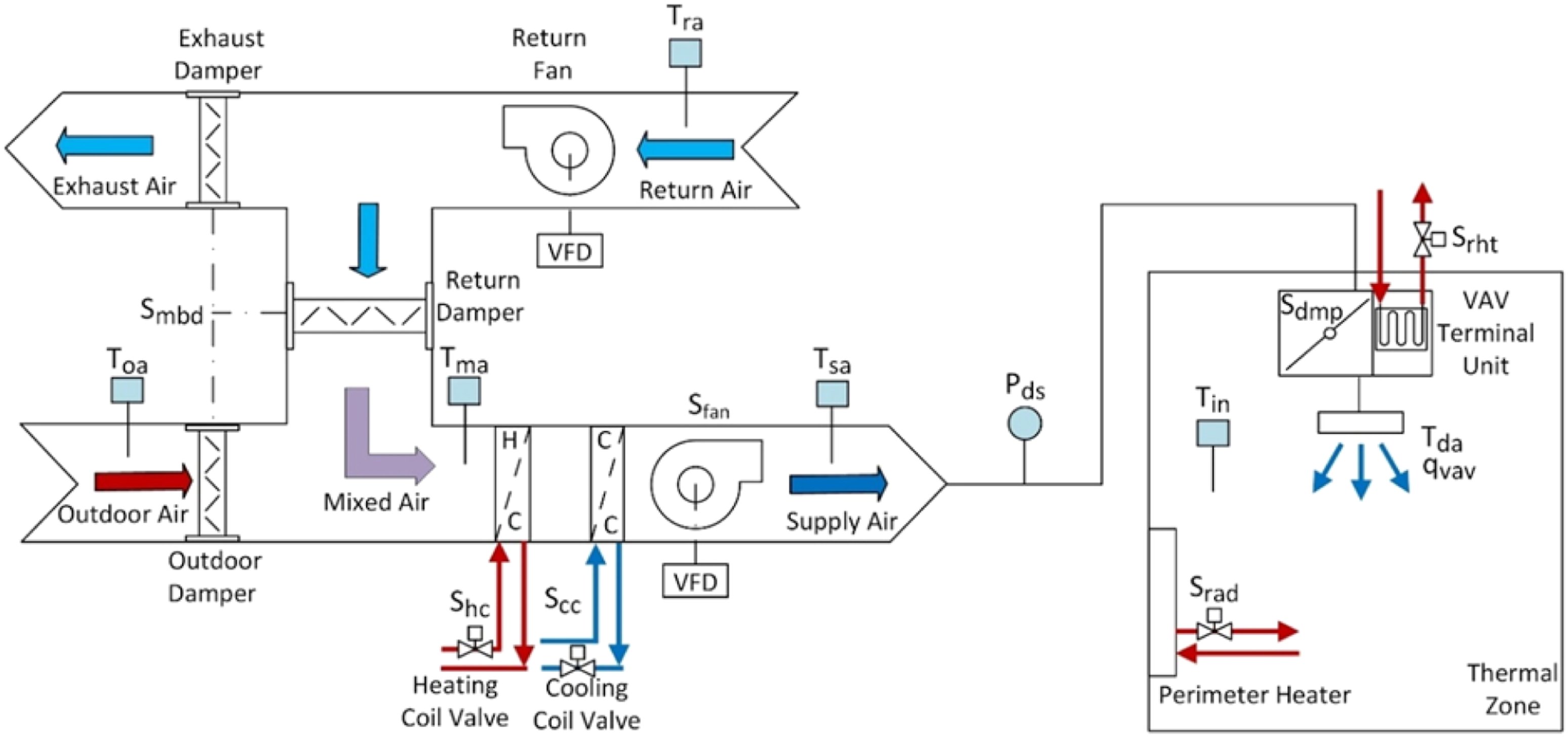
A schematic of an AHU and a perimeter thermal zone of this study.
To begin with, all possible hard and sequencing logic actuator faults of the system-level (AHU) and zone-level (VAV) are identified based on the previous work that has been done on the detection of these faults. Then, the faults are checked sequentially, considering their hierarchical dependencies to avoid false alarms. Since hard faults may trigger an alarm for sequencing logic faults, a complete fault diagnostics framework should prioritize hard faults over sequencing logic faults. For example, a stuck outdoor air damper may trigger the alarm for an inappropriate economizer programming fault, or a stuck VAV damper may trigger the alarm for an improper duct static pressure setpoint reset fault. Also, system-level faults should be prioritized over zone-level faults since the faults higher in the hierarchy affect the detectability of the faults lower in the hierarchy, and this approach avoids false positive alarms. Therefore, faults are checked in the following order: hard faults at the system-level→ hard faults at the zone-level → sequencing logic faults at the system-level→ sequencing logic faults at the zone-level. This holistic approach primarily considers the detectability of a fault in the presence of other faults.
The proposed FDD sequential hierarchical framework is summarized in a flowchart shown in Figure 2. In addition, visualization is provided for each classification in Figure 2, indicating the expected behaviour to facilitate the interpretation of each fault. The proposed framework is designed to address two main issues: (1) detectability: a fault may conceal another fault, causing a false negative. Similarly, a fault may trigger another fault alarm causing a false positive. Hence, it is difficult to isolate low-level faults when high-level faults are present in a VAV AHU system. For example, a broken perimeter heater valve in one of the zones may cause an AHU to operate within the unoccupied hours and may trigger the alarm for improper AHU mode of operation fault. Therefore, the framework prioritizes hard faults over sequencing logic faults to avoid false positives and false negatives. (2) Significance: faults with greater impacts on a VAV AHU system’s energy and comfort performance should be prioritized over low-impact faults. For example, while a stuck open/closed heating coil valve in an AHU affects many zones, a faulty reheat coil valve affects a single zone. Similarly, while an improper AHU supply air temperature setpoint reset affects many zones, an improper zone temperature setpoint affects only a single zone. Hence, system-level faults are prioritized over zone-level faults in the framework. FDD framework for hard and soft actuator faults in multiple-zone VAV AHU systems.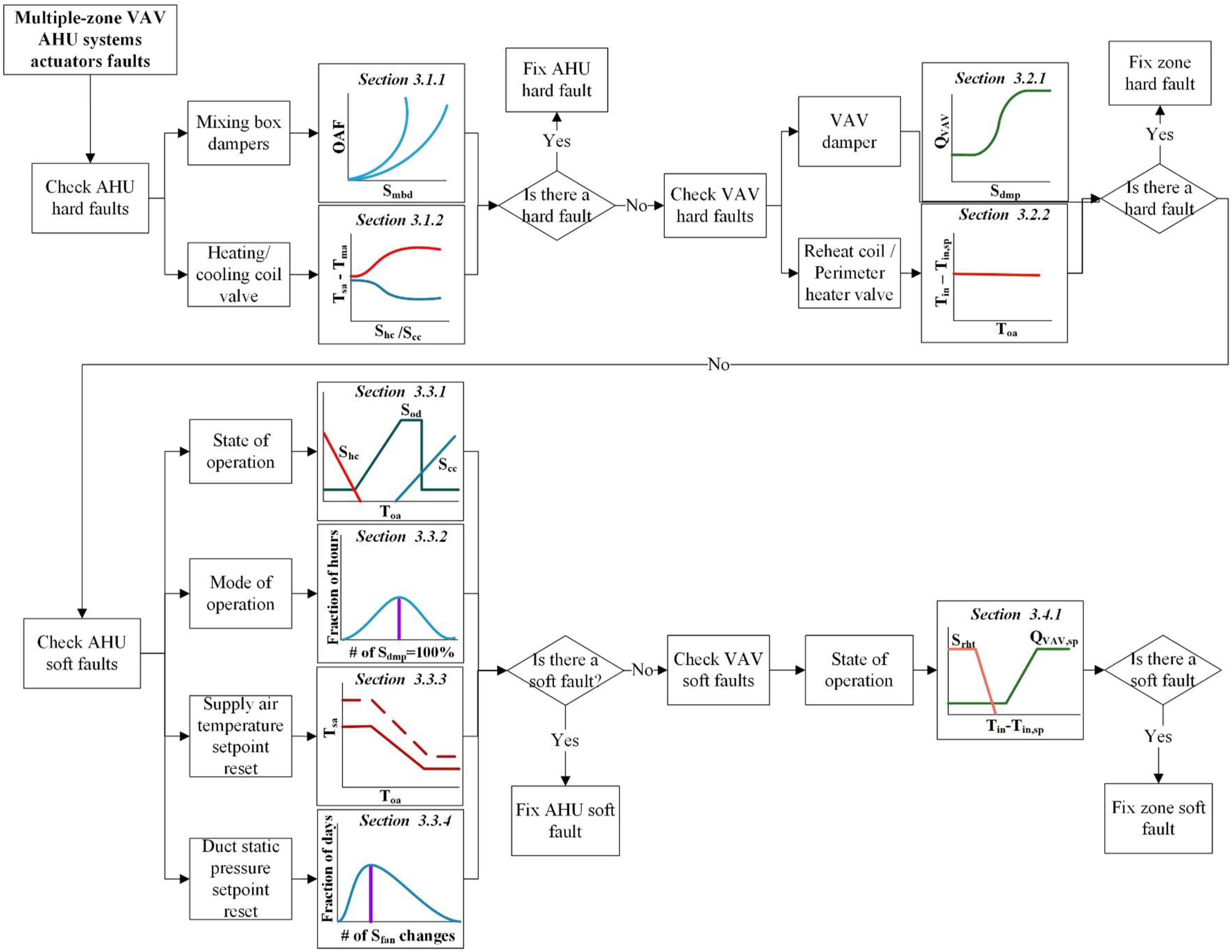
The practical approach for the proposed FDD framework will be as follows: when the framework encounters a hard fault, the facility manager will go ahead and fix the hard fault before the FDD system begins generating alarms for soft faults. When hard faults are fixed, the framework will go beyond the hard faults in the next round and generate alarms for sequencing logic faults if there are any in the system or zones.
The next sections discuss each fault category, providing inverse models characterizing the heat and air mass balance explaining the normal behaviour along with illustrative examples from existing buildings to demonstrate the approach. The examples are selected from different systems rather than a single VAV AHU system. The reason for that is, among the 10 VAV AHU systems that the authors studied in this paper, finding a system with all common hard and sequencing logic faults mentioned in the framework was not possible. Hence, the authors ended up introducing examples from different systems to illustrate each fault category. However, a discussion about the impact of a fault on the detectability of other faults suppressed in the framework is provided for each fault category to demonstrate the sequential order.
Detection of AHU hard faults
As shown in Figure 2, the suggested FDD framework first looks for hard faults in an AHU. This category includes faults such as stuck/broken/leaking mixing box dampers and heating/cooling coil valves. These physical problems that affect the device’s function usually affect occupant comfort, and indoor air quality and consequently are easier to detect. However, they may remain unnoticed, such as a stuck/broken/leaking mixing box damper compensated by a heating/cooling coil valve in which the AHU’s supply air temperature meets its setpoint at the cost of additional energy to heat/cool the outdoor air.
Mixing box damper fault
In order to detect a mechanical failure of the mixing box damper, the relationship between the mixing box damper control signal and the outdoor airflow fraction (OAF) of the AHU supply air should be investigated. Note that the AHU mixing box consists of outdoor, return, and exhaust air dampers and these three dampers are controlled by the same mixing box damper control signal monitored by a BAS. 31 The outdoor and exhaust air dampers act in a direct way with the control signal, whereas the return air damper act in a reverse direction. 31
When the AHU is in the economizer state (heating and cooling coils are not in use), neglecting the heat added by the supply fan, the OAF can be defined as 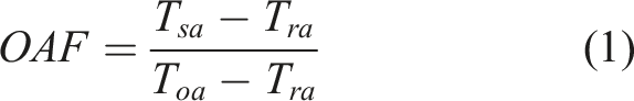
Based on the Air Movement and Control Association (AMCA) publication, the idealized laboratory tests have demonstrated that the inherent relationship between the outdoor air damper position and OAF is exponential.
34
The installed dampers on an experimental basis display a logarithmic relationship that varies based on the difference between atmospheric pressure and the pressure in the mixing box.
35
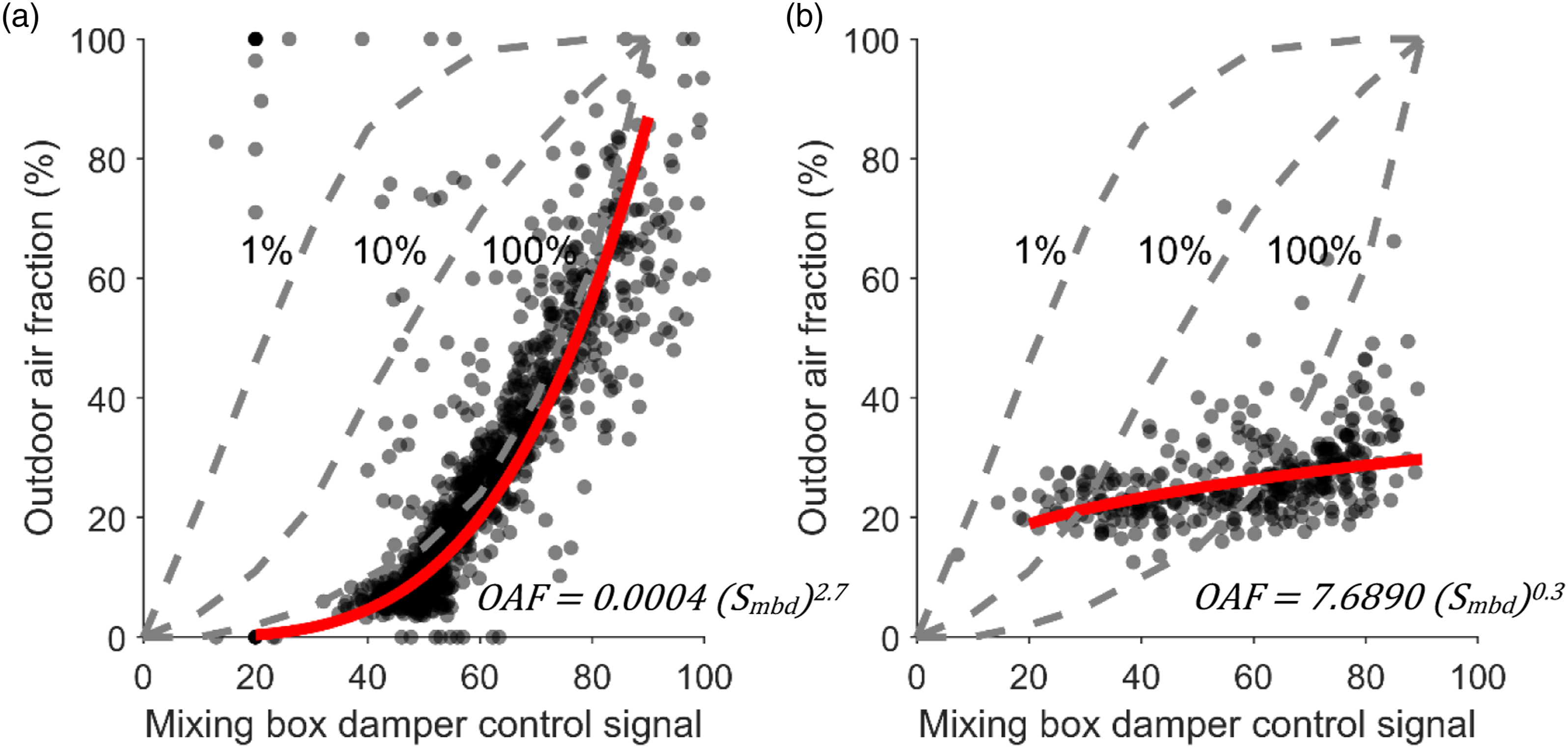
Figure 3 shows the relationship between OAF and outdoor air damper position adapted from AMCA for three different damper authorities: 1%, 10%, and 100%.
34
Damper authority or characteristic ratio is defined as the percentage of open damper pressure drop to total system pressure drop. It demonstrates a damper’s influence on the flow when it operates at a nearly fully open position. 100% damper authority represents the inherent curve measured under laboratory conditions, with a constant differential pressure across the damper, while 1% and 10% represent the installed damper characteristics. Therefore, an outdoor air damper with normal performance lies within 1% and 100% of the damper authority range. On the other hand, an out-of-range curve represents a leaky, broken, or stuck damper. For example, Figures 3(a) and (b) show the relationship between the mixing box damper control signal and OAF in the economizer state for two different AHUs. The regression model fit shown as a solid red line is an exponential function defined as OAF versus mixing box damper control signal (a) normal behaviour (b) outdoor air damper is stuck/leaking.
Heating/cooling coil valve fault
The mechanical failure of the heating/cooling coil valve can be detected by investigating the relationship between valve position and temperature change across the heating/cooling coil. The temperature change across the coil is defined as ΔT=T
sa
-T
ma
. In the absence of a mixed air temperature sensor, T
ma
can be estimated as Temperature change across heating/cooling coil valve versus heating/cooling coil valve position (a) normal behaviour (b) heating coil valve is broken.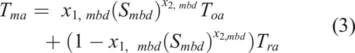
Detection of VAV zone-level hard faults
After checking an AHU’s hard faults, the proposed FDD approach looks for the hard faults at the zone-level. This group of faults includes faults such as stuck/broken/leaking VAV dampers, perimeter heater valves and reheat coil valves.
VAV damper fault
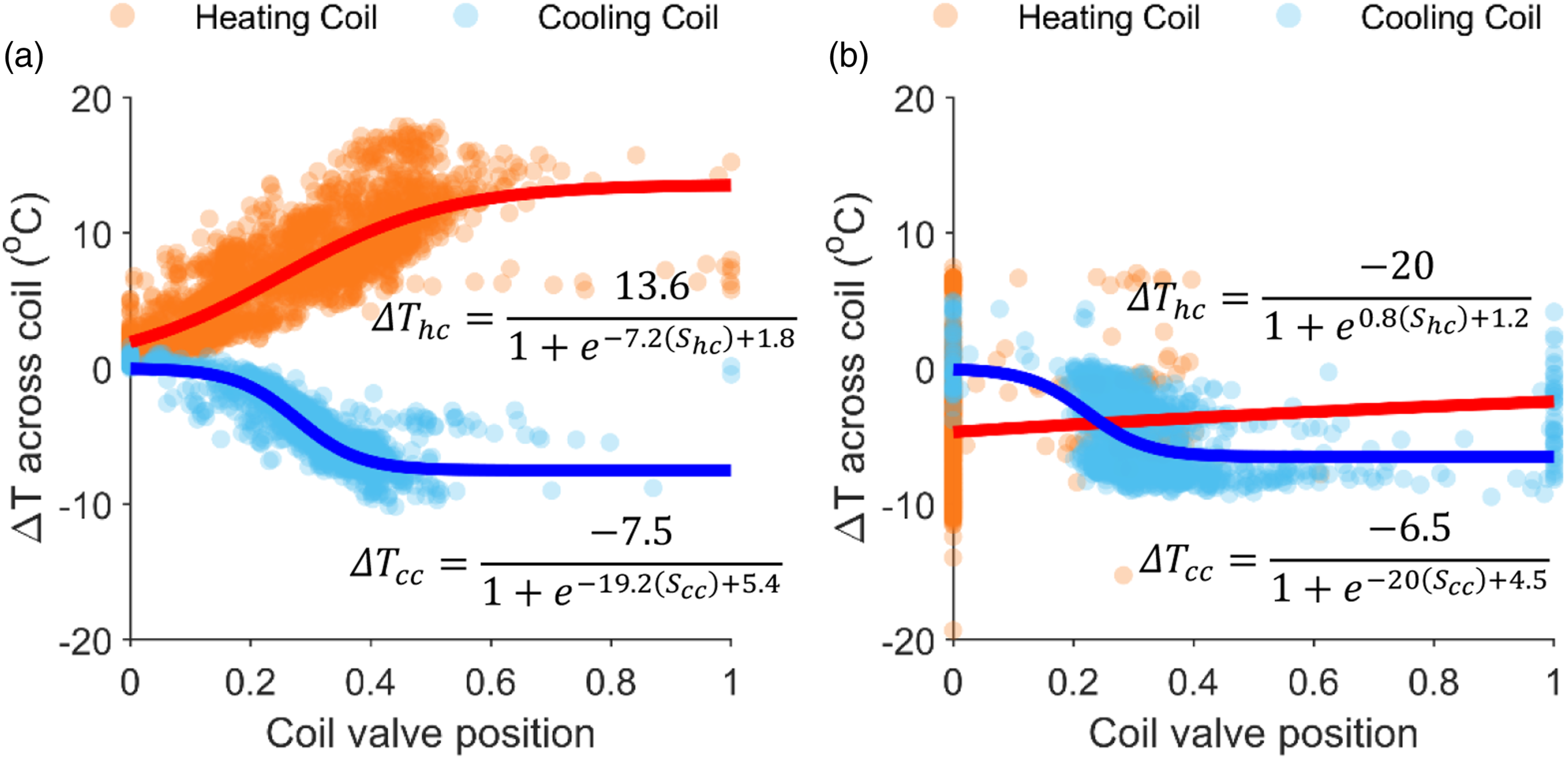
To detect the mechanical failure of VAV dampers, the relationship between the damper position and the airflow delivered to the VAV is investigated. There is no direct relationship between VAV damper position and VAV airflow because the damper position depends on the VAV inlet size and downstream static pressure in the system. However, there is a direct relationship between the differential pressure across the airflow sensor and the VAV airflow. The airflow of a VAV is defined as VAV airflow versus VAV damper position (a) normal behaviour (b) damper stuck partially open.
Reheat coil/perimeter heater valve fault
A zone heating device actuator’s physical failure, either a reheat coil valve or a perimeter heater valve, can be detected by examining the relationship between the zone temperature error (temperature difference between measured zone temperature and setpoint zone temperature) and outdoor air temperature. Note that VAV damper behaviour directly impacts zone temperature error, and a faulty VAV damper may appear as a reheat coil/perimeter heater valve fault. However, detecting the VAV damper hard fault before detecting the zone valve fault will avoid this false alarm. Similarly, a hard fault at the AHU dampers or valves causes an unreasonable supply air temperature which negatively impacts the zone temperature error and may appear as a zone valve fault. Again, this fault is previously detected in the framework, and the false alarm is avoided.
Figure 6 shows the relationship between zone temperature error and outdoor air temperature during the heating season for two different zones served by the same AHU. For example, in Figure 6(a), when the outdoor air gets cold, the perimeter heater valve/reheat coil valve opens, and the indoor temperature rises and meets its setpoint. However, in Figure 6(b), as the outdoor temperature gets cold, the indoor temperature drifts away to the colder temperatures and cannot be maintained at its setpoint. Therefore, the zone temperature errors (T
in
-T
in,sp
) are negative values in the cold outdoor air temperatures. Note that if a perimeter zone has both reheat coil and hydronic perimeter heater devices, this examination does not reveal which valve is faulty, and the facility manager needs to examine both valves on-site to discover the defective valve. However, having a discharge air temperature (T
da
) sensor downstream of the reheat coil improves the detectability of a reheat coil valve fault. Zone temperature error versus outdoor air temperature behaviour in two zones served by the same AHU. Subfigure (a) presents the normal behaviour and (b) represents the behaviour with a broken perimeter heating device actuator.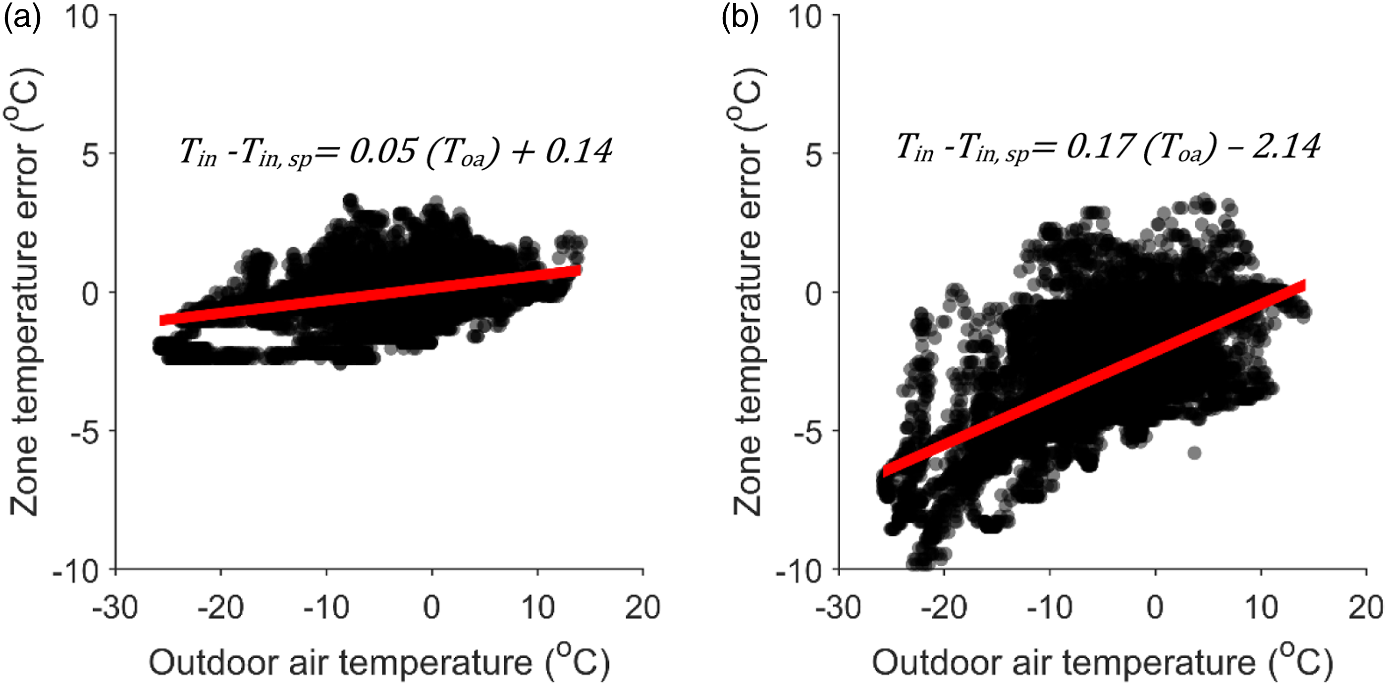
Detection of AHU sequencing logic faults
The AHU sequencing logic faults are divided into four categories: improper AHU state of operation, abnormal changes in AHU modes of operation, inappropriate duct static pressure setpoint reset, and inappropriate supply air temperature setpoint reset. These faults usually remain unnoticed as they compensate for each other’s impact, such as simultaneous heating and cooling, and do not cause occupants’ discomfort.
Sequencing faults affecting the state of operation of AHUs
As per ASHRAE Guideline 36,
12
an AHUhas four states of operation: heating, free cooling with modulating outdoor air damper, mechanical + free cooling, and mechanical cooling with minimum outdoor air damper position (Figure 7). A schematic illustrating a VAV AHU system’s operating state.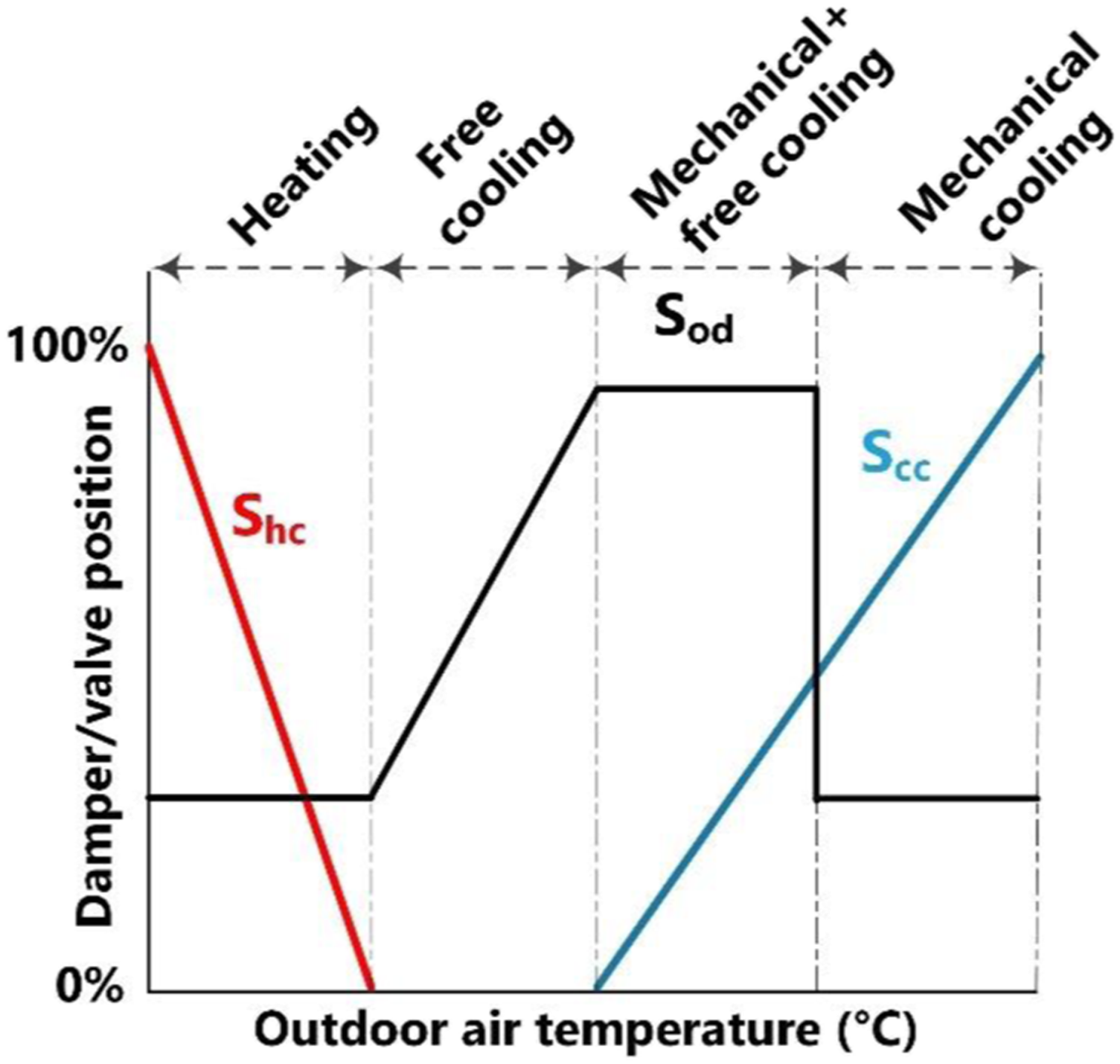
Improper AHU state of operation consists of two possible major faults: inappropriate economizer programming and simultaneous heating and cooling.
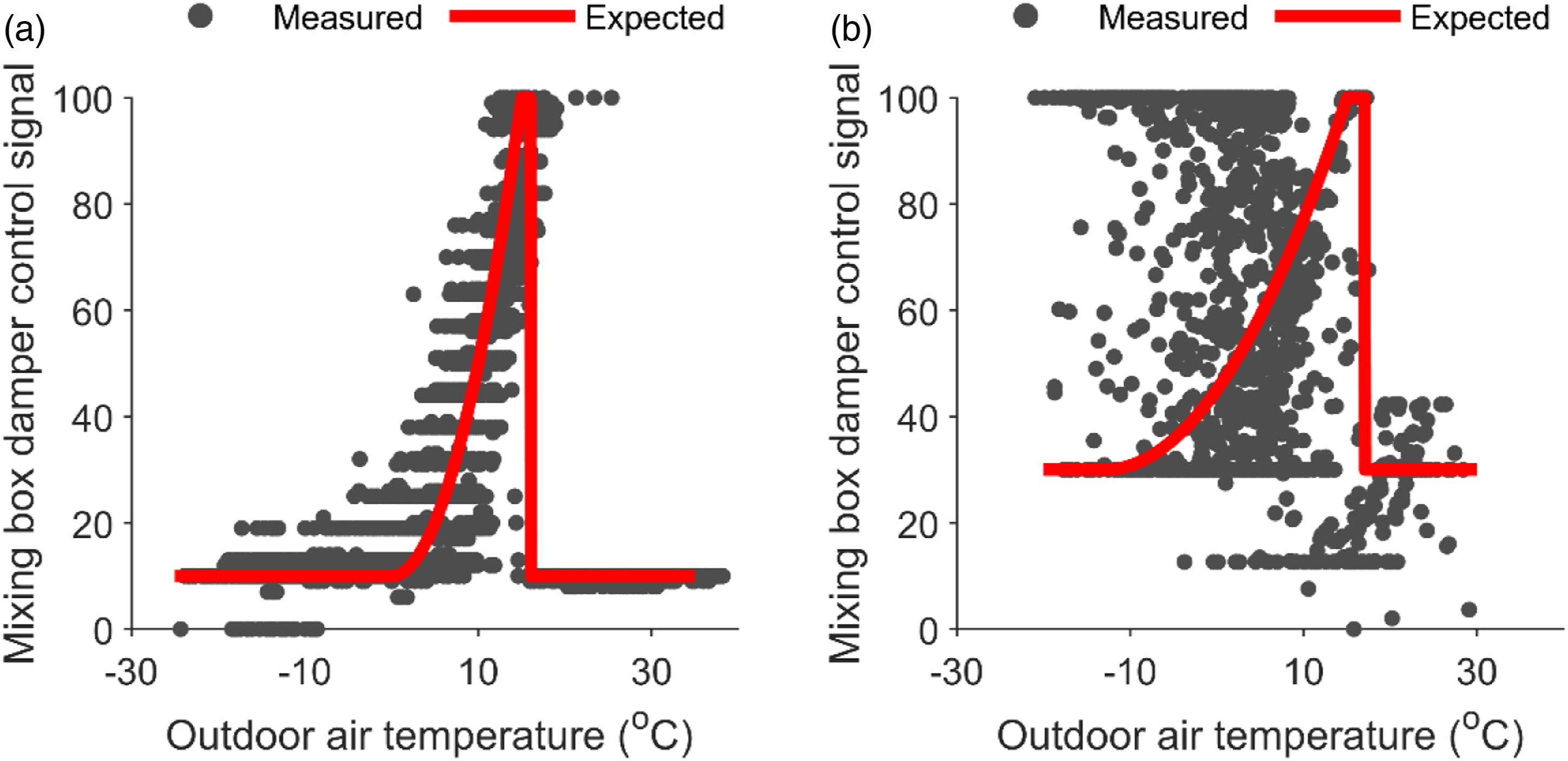
To detect the economizer programming errors, the ideal and measured mixing box damper control signals are compared. To estimate the ideal mixing box damper control signal (S
mbd-ideal
), the behaviour of the damper in each state of operation is analyzed. In the mechanical cooling with economizer state - when the outdoor air temperature is less than return air temperature but more than the supply air temperature - the outdoor air damper adjusts to 100% open, and the return air damper closes in sequence with cooling coil valve to maintain the supply air temperature. In the free cooling state, when the supply air temperature is less than the return air temperature but more than the outdoor air temperature, OAF is calculated based on equation (1)
Note that equation (1) neglects the latent heat to ensure transferability to AHUs without return and supply air humidity sensors. This assumption can be considered reasonable because in the free cooling state, the heating and cooling coil valves are closed, and the outdoor air temperature is not extremely hot and cold. Hence the outdoor and return air humidity ratios are close enough that neglecting the humidity does not cause a significant difference in calculating S
mbd-ideal
.
8
The outdoor air damper remains at its minimum required position setting in the mechanical cooling and heating states. ASHRAE 90.1
37
recommends a high limit temperature of 21°C for buildings located in climate zone 6A (location of systems under this study) to account for the availability of economizer performance in cool but high humidity outdoor air conditions. Therefore, the ideal mixing box damper control signal is summarized as follows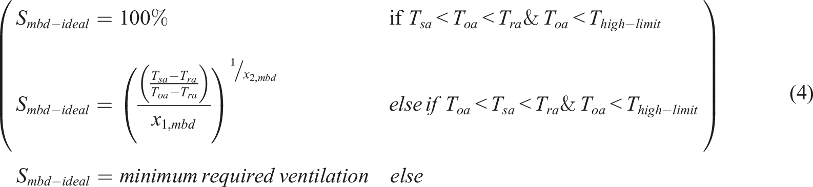
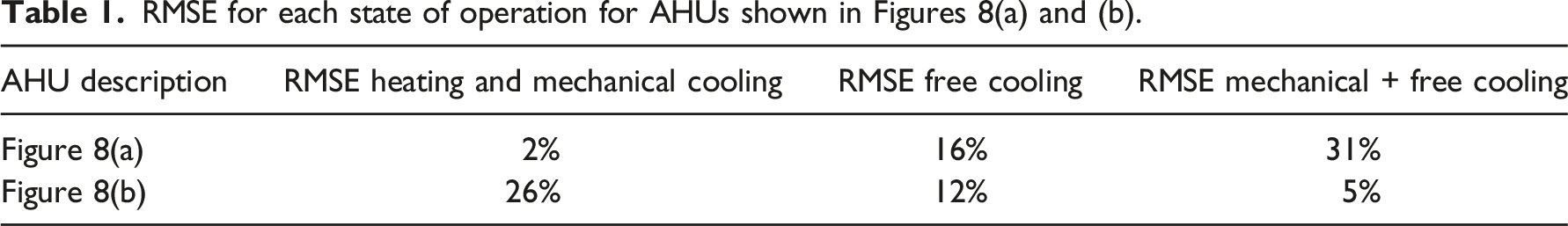
The measured and ideal Smbd are compared to detect this fault. The difference between the measured and ideal Smbd is computed with regard to the root mean squared error (RMSE) as follows Measured and expected mixing box damper control signal (a) improper economizer programming for free + mechanical cooling state (b) improper economizer programming for heating state (i.e. simultaneous heating and economizer). RMSE for each state of operation for AHUs shown in Figures 8(a) and (b).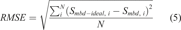
Sequencing faults affecting the mode of operation of AHUs
Irregular AHU mode change is a sequencing logic fault that causes irregular changes in the supply fan state and, consequently, it triggers most actuators in both system- and zone-levels when they are not needed or inactivates them when needed. However, If there is a broken perimeter heater valve in a zone, the zone can be colder than the unoccupied mode heating temperature setpoint or warmer than the unoccupied mode cooling temperature setpoint. In that case, It makes the AHU change modes abnormally, and it is impossible to isolate whether it is an AHU mode changes logic mistake or a broken zone valve. This false alarm is suppressed as the framework checks zone actuators to ensure they are free from hard faults before going to the AHU mode change logic fault.
As per ASHRAE 36,
12
an AHU system has seven operating modes: occupied, cool-down, set-up, warm-up, set-back, freeze protection set-back, and unoccupied. A supply fan runs when the system is in the cool-down, set-up, or occupied mode. If there are any reheat coils or perimeter heaters in the zones, the supply fan also runs when the system is in set-back or set-up mode, which means all modes except unoccupied. In order to detect the abnormal changes in the AHU mode, the number of daily fan state changes in an AHU is investigated. Two different AHUs are investigated, and the results are displayed in Figure 9. As shown in Figure 9(a), the AHU’s fan state changed twice per day on almost 70% of weekdays. It means the supply fan followed the operating schedule (turned on in the morning and off in the evening). By contrast, in Figure 9(b), the fan state did not change on almost 45% of the weekdays, which means the fan ran continuously or did not run at all. During the unoccupied periods, the fan does not rapidly cycle on and off between unoccupied and set-back/set-up modes if the indoor temperatures do not become excessively cold or hot due to factors such as leaving an open window overnight or not providing a dedicated cooling system for IT rooms (overheating). Therefore, the authors chose a 30% threshold for detecting this fault considering the times that the building is unoccupied, such as holidays with no mode changes. This means that for 70% of the weekdays, the fan status should change twice daily. Hence, if an AHU experiences less than two daily operating mode changes for more than 30% of the weekdays or experiences more than two daily operating mode changes for more than 30% of the weekdays, there is an abnormal change in AHU mode. Distribution of fan state changes per weekday for a VAV AHU system in which the supply fan (a) turned on-off twice on 70% of the days and (b) did not turn off (ran continuously) on 45% of the days.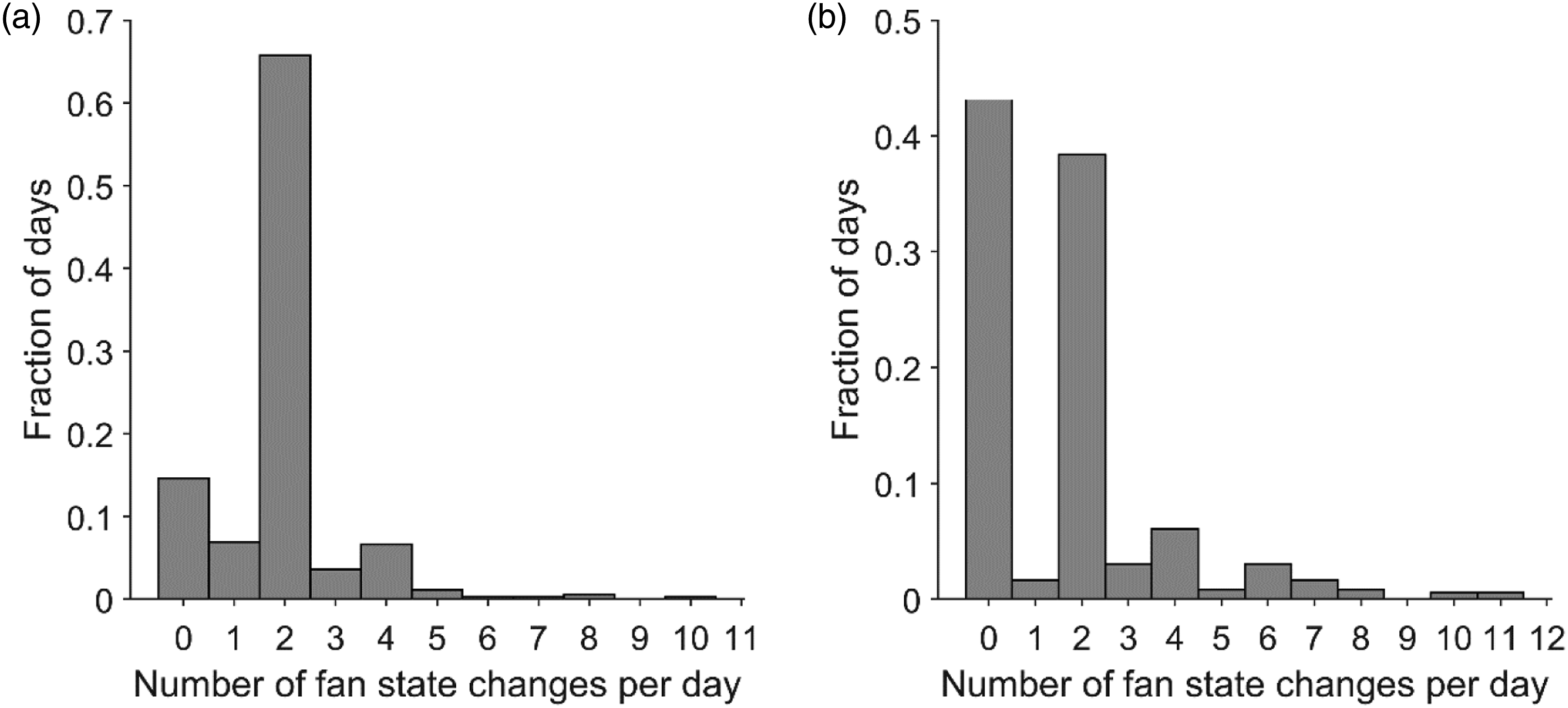
Inappropriate supply air temperature setpoint reset
Traditional practice was to set the supply air temperature at a constant value to satisfy the maximum cooling load, leading to an increase in the reheat load. 38 ASHRAE 36 12 recommends occupied mode supply air temperature set-point reset logic to be a combination of reset by outdoor air temperature (to reduce fan energy during warm weather) and zone feedback (the supply air temperature needed to satisfy the zone requiring the coldest air to meet space temperature setpoint). In order to maximize economizer operation and minimize reheat losses, offset partially by higher fan energy, ASHRAE 36 12 selects a higher and a lower limit for the range of outdoor air temperatures used for the outdoor air temperature reset logic.
Note that a broken heating/cooling coil valve in an AHU negatively affects the supply air temperature setpoint, making it impossible to isolate whether it is a reset logic mistake or a broken AHU valve. This false alarm is suppressed as the framework checks AHU coil valves to ensure they are free from hard faults before going to AHU sequencing logic faults. Therefore, supply air temperature setpoint reset logic fault cannot be detected before ensuring AHU valves are functional.
In order to detect the faults associated with wrong supply air temperature setpoint reset, this paper introduces the higher and lower limits for the supply air temperature setpoints from the literature. Gunay et al.
31
examined several outdoor temperature-based supply air temperature setpoint reset profiles proposed by researchers and selected the profile with a more extensive range encompassing the other profiles. This fault is detected if the supply air temperature is outside the range limited by higher and lower setpoint profiles for more than 30% of the operating hours. The measured supply air temperature and the upper and lower bounds for the expected supply air temperature reset profile as a function of the outdoor temperature (proposed by Gunay et al.
31
) are shown in Figure 10 for two different AHUs. Although in Figure 10(a), the supply air temperature setpoint decreases as the outdoor temperature increases, the measured supply air temperatures are out of the range for 42% of the operating hours; this AHU has the minimum out of the range percentage among the studied systems. Whereas in Figure 10(b), the measured data are 63% out of the profile ranges with the constant temperature setpoint. Measured supply air temperature and expected supply air setpoint profiles versus outdoor air temperature, measured supply air temperatures are out of the range for (a) 42% of the operating hours (b) 63% of the operating hours.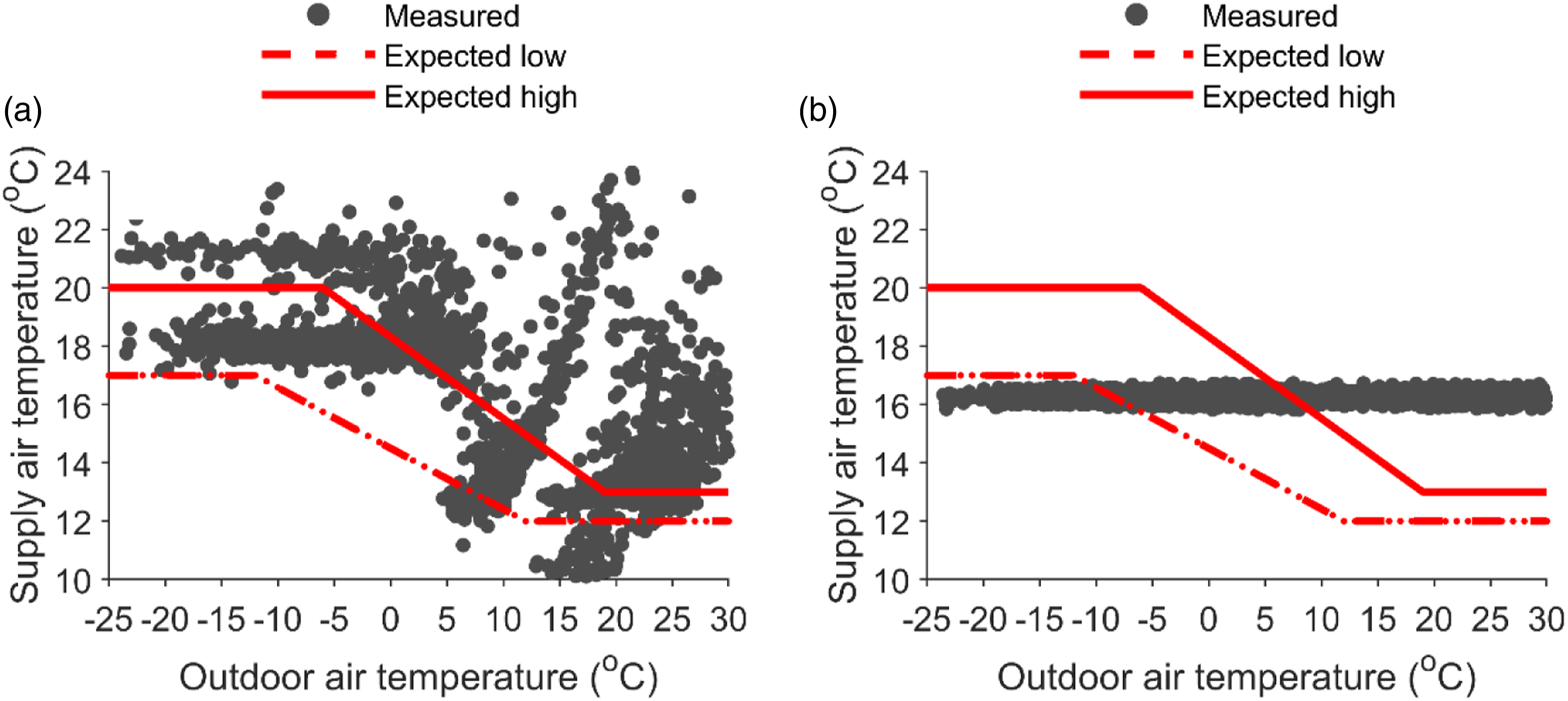
Inappropriate duct static pressure setpoint reset
Typically, the VAV damper positions react to zone temperature setpoints. Then the supply fan reacts to the resulting damper positions by modulating its speed to maintain the duct static pressure. Applying an appropriate duct static pressure setpoint reset logic effectively reduces fan energy in AHU VAV systems. 39 However, if there is a broken VAV damper in one of the zones, it might appear as a fully open/closed damper. That single broken VAV damper ruins the duct static pressure setpoint reset logic – making it impossible to isolate whether it is a reset logic mistake or a broken VAV damper. This false alarm is suppressed as the framework checks all VAV damper actuators to ensure they are free from hard faults before checking the duct static pressure reset logic fault. Therefore, duct static pressure setpoint reset logic fault cannot be identified before ensuring that all VAV dampers are functional.
ASHRAE 90.1 37 for systems with direct digital control of individual zone boxes reporting to the central control panel recommends resetting static pressure setpoint based on the zone requiring the most pressure, i.e. the setpoint is reset lower until one zone damper is nearly wide open and is reset higher when more zones have nearly fully open VAV dampers. In the critical zone reset strategy, the fan speed is controlled so that the static pressure at the sensor location is held constant by keeping at least one zone damper wide-open at any load conditions during operation. 40 The concept behind critical zone control is to keep the dampers as open as possible when the load decreases by resetting the static pressure setpoint to a lower value. Basically, the maximum energy saving is achieved when the damper at the critical zone (zone with the highest pressure drop and airflow rate) is kept wide open at any load condition. 40 One approach to implement the critical zone setpoint is using the PID controller loop to adjust the setpoint to maintain the critical zone damper position at 90% open. 39 As proposed by the authors, the inappropriate duct static pressure setpoint reset fault is detected if the fraction of operating hours when none or all of the VAV dampers is more than 90% open is 20% or more. This is to say, the duct static pressure setpoint is high, and the AHU fan pushes high-pressure air while the dampers are partially or fully closed if none of the VAV dampers are fully open for at least 20% of the operating hours. Conversely, if the fraction of operating hours when all VAV dampers are more than 90% open is 20% or more, the setpoint is low, and zones are starved to receive adequate air.
Figure 11 represents the fraction of time-based on the number of fully (more than 90%) open VAV dampers. In Figure 11(a), the distribution of fully open dampers is not concentrated on one side of the graph, demonstrating that the pressure setpoint is low for parts of the year (likely summer), and as many as 40 zones are starving. Whereas for some parts of the year (likely winter), the pressure setpoint is high as almost all dampers are partially closed. While in Figure 11(b), there is a concentrated distribution toward the left side of the graph, demonstrating that none of the dampers are fully open for more than 65% of the operating hours, indicating a high-pressure setpoint. Distribution of the number of fully open dampers for a VAV AHU system in which (a) pressure setpoint is too low and too high at different periods and (b) pressure setpoint is too high. Note that when the pressure setpoint is too low, many zones will have their dampers fully open, and when the pressure setpoint is too high, none of the zones will have their dampers fully open.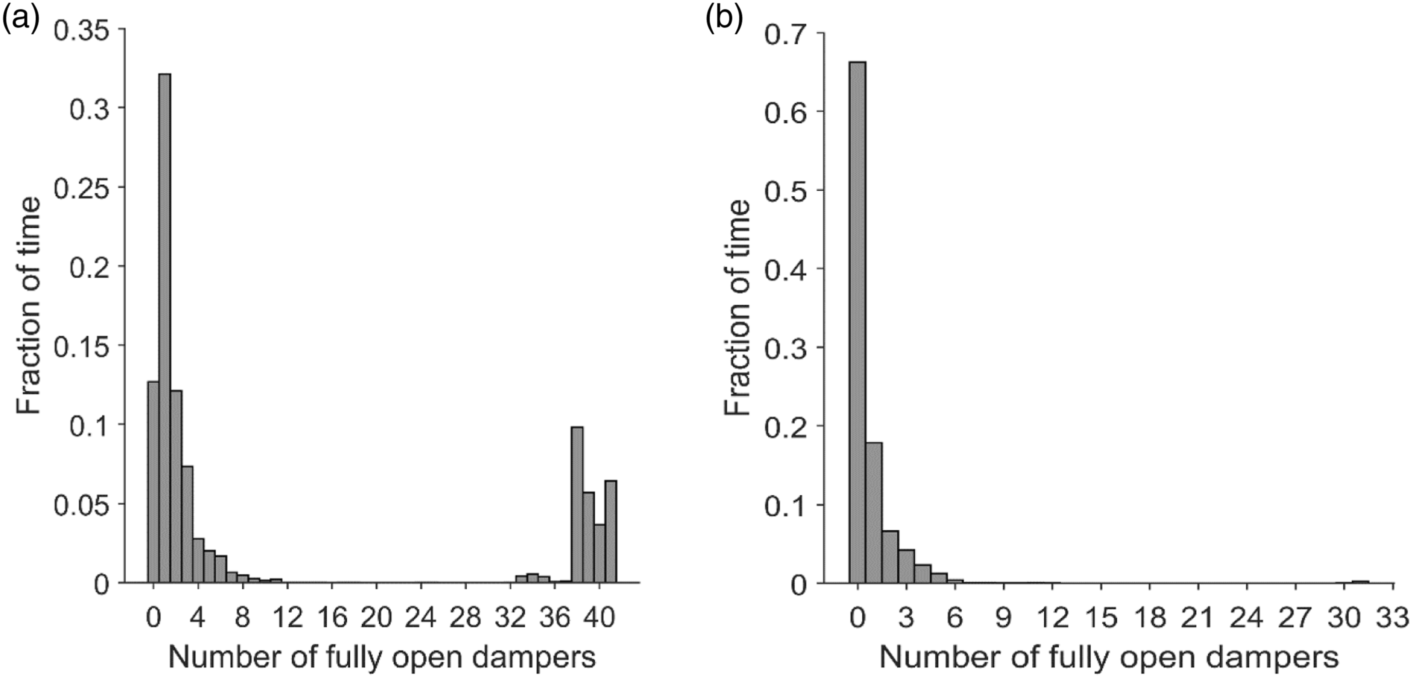
Detection of VAV zone sequencing logic faults
The VAV sequencing logic fault is defined as one category called the inappropriate state of operation. It is assumed that the VAV box has no different operation modes from the AHU.
Inappropriate state of operation
As per ASHRAE 36,
12
the sequencing logic diagram for a typical single duct VAV box with a hydronic reheat coil is shown in Figure 12. When the indoor temperature rises above the cooling setpoint, the VAV damper opens up and delivers higher airflow rates to the zone proportionally. When the indoor temperature falls below the cooling setpoint, the VAV damper gradually closes until it provides the minimum required flow rate for ventilation.
41
The reheat coil valve starts opening when the indoor temperature gets to the heating setpoint.
41
Note that it is assumed a fixed airflow rate equal to the minimum required ventilation is provided by the VAV box in the heating state, and the perimeter heaters compensate the heat loss caused by infiltration transmission through walls, windows, etc. The distance between the zone heating setpoint and the zone cooling setpoint is called deadband, where the VAV is neither in heating nor cooling state. A schematic of sequencing logic for a single duct VAV box with reheat coil.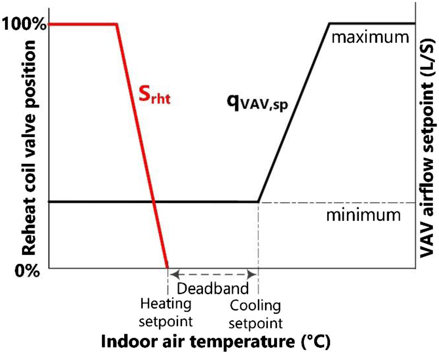
Simultaneous heating and cooling and inappropriate minimum/maximum airflow setpoints are the sequencing logic faults at the zone-level. However, if there is a faulty reheat coil valve or VAV damper in the zone, it negatively impacts the VAV state of operation, making it impossible to isolate whether it is a zone state of operation mistake or a broken reheat valve/VAV damper. This false alarm is suppressed as the framework checks all zone actuators’ hard faults before going to zone sequencing logic faults. Therefore, zone state of operation fault cannot be detected before ensuring that all zones’ valves and dampers are operational.
To detect the faults associated with the inappropriate state of operation at the zone-level, the relationship between the reheat coil valve position and VAV airflow setpoint based on the zone temperature error during the occupancy hours is analyzed. As shown in Figure 13(a), when the indoor temperature is colder than the setpoint temperature, the reheat coil valve opens, and the VAV airflow setpoint is at its minimum rate to provide the required ventilation. Conversely, when the indoor temperature exceeds the setpoint temperature, the reheat coil valve remains closed, and the VAV airflow setpoint increase to achieve its maximum rate. Therefore, the VAV programming appears as expected for this zone. However, Figure 13(b) represents a faulty VAV state of operation where the reheat coil valve stays open during the cooling state (when the VAV airflow setpoint is at its maximum rate). In other words, the VAV simultaneously heats and cools the zone. Reheat coil valve position and VAV airflow setpoint versus zone temperature error (a) normal behaviour (b) simultaneous heating and cooling.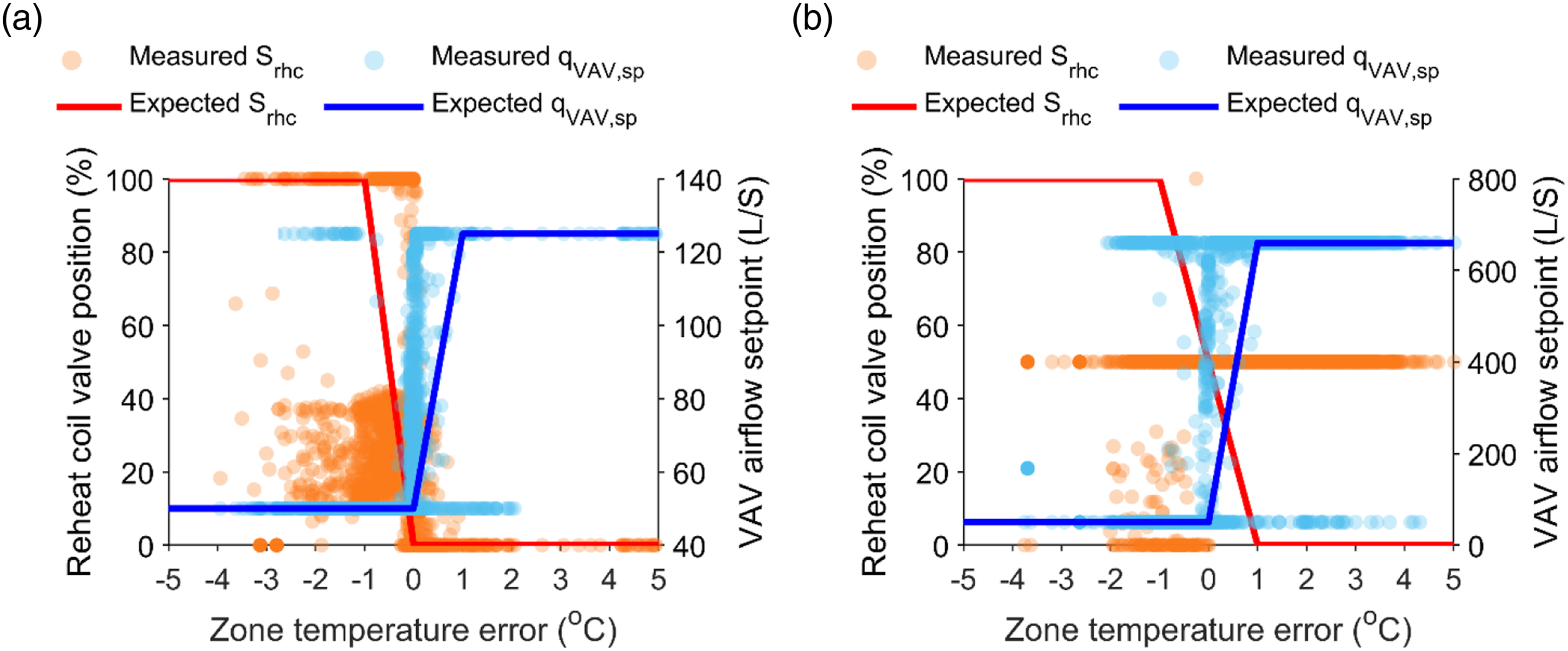
A discussion point worth mentioning at the end of the framework is that soft faults are not only affected by hard faults but may also be affected by other soft faults. For example, an incorrectly implementation of maximum VAV airflow setpoint by BAS operator, can make a zone too cold/too hot which may negatively impact the supply air temperature reset program or mode of operation behaviour. Therefore, soft faults at the zone-level may trigger false alarm for the soft faults at the system-level. However the system level soft faults still are prioritized over zone-level soft faults to triage high-impact faults in the system.
Limitations and future work
This paper proposed a new FDD framework considering fault detectability and significance. The Authors provided illustrative examples for each fault category and discussed dependencies between these fault categories; however, the framework was not applied on a single VAV AHU system from beginning to end. Demonstration of the framework on a complete case study should be a future work need. Moreover, this paper only focused on controls hardware and sequencing logic faults affecting the actuators of multiple zone VAV AHU systems. The examples provided in this study are selected from clean data after ensuring that sensors’ operation does not have an impact on the identified faults. Faults such as sensor biases that impact the parameters studied in this paper should be identified before employing this approach. Future research can extend the framework to other systems and components.
Furthermore, the proposed FDD framework is more practical and gives an envisioning interpretation for the experts in facilities management. In fact, the primary purpose of this framework is to provide a visual tool to facility managers to interpret the data and fix the faults on-site. Therefore, the thresholds may vary depending on how facility managers want to compromise between true positions and false negatives. Hence, the thresholds can be defined more loosely at the beginning of the procedure. Once the framework presented in Figure 2 is followed from beginning to end and addresses the identified faults, more aggressive thresholds can be adopted in the second round. In the long run, FDD is an iterative process. As the facility is adjusted to the expected level of performance and the most severe and urgent issues are cleared (while the framework is followed from beginning to end), the thresholds can be reduced, and less significant issues can be addressed. More research is needed for the selection of appropriate thresholds for each fault using inverse modelling.
In addition, this paper took an FDD holistic approach for the actuator faults at the system- and zone-level (airside systems) while many actuators are located in the HVAC system upstream of the AHUs. These devices provide chilled water and steam/hot water for the AHUs and zone-levels such as boilers, chillers, pumps, etc. A fault occurring upstream of an AHU, such as the incorrect temperature of hot/chilled water supply/return to or from heating/cooling coil, may affect occupants’ thermal comfort at the zone-level. Therefore, future work can take a complete approach and include the FDD upstream of the AHUs.
Lastly, estimating the impact of corrective action on energy savings or indoor environment quality benefits is a worthwhile discussion for future work.
Conclusion
This paper introduced a new FDD framework for actuator faults at the system- and zone-level. The authors gathered the actuators’ hard faults (physical failure) along with the AHU and VAV soft faults (sequencing logic mistakes) that have adverse effects on the actuators’ behaviour in multiple zone VAV AHU systems. Previously, researchers have addressed these faults individually using FDD methods (quantitative, qualitative, and process history-based) either at the zone- or system-level. In contrast, the authors took a holistic approach that considers the significance of zone-to-system hard and soft fault interactions. The proposed framework facilitated the fault detectability of the faults masked by other faults and suppressed false alarms caused by other faults in multiple-zone VAV AHU systems. This holistic FDD framework was summarized in a sequential hierarchical chart in conjunction with illustrative graphs showing the normal behaviour of each category. In the proposed FDD framework, first AHU hard faults, then VAV zone hard faults, next AHU soft faults, and finally VAV zone soft faults were checked. Finally, the framework was discussed with illustrative examples from 10 different VAV AHU systems. The proposed FDD framework successfully isolated the root cause of hard faults such as outdoor air damper, heating/cooling coil valve, VAV damper and preheat coil/perimeter heater valve and sequencing logic faults such as inappropriate AHU state of operation, inappropriate AHU mode of operation, improper duct static pressure/supply air temperature setpoint reset and inappropriate VAV state of operation.
Footnotes
Acknowledgements
The authors also thank National Research Council Canada (NRC), Public Services and Procurement Canada (PSPC), and Carleton University Facilities Management and Planning for the data used in this paper.
Declaration of conflicting interests
The author(s) declared no potential conflicts of interest with respect to the research, authorship, and/or publication of this article.
Funding
The author(s) disclosed receipt of the following financial support for the research, authorship, and/or publication of this article: This research is supported by funding provided by the Natural Science and Engineering Research Council of Canada (NSERC) (CRDPJ 516465) and CopperTree Analytics (CRDPJ 516465).