
Abstract
All around the world, modern elevators transport safely and comfortably millions of passengers and freight each day. Since modern elevators emerged at the beginning of the 19th century, several advances have risen in this transportation system. Among them, safety conditions were significantly improved. Therefore, modern elevators must be equipped with safety protection systems to assure safety conditions and avoid accidents. An overspeed governor is one of the components of such a safety system. It acts as a stopping mechanism when the elevator car reaches an excessive velocity, known as tripping speed. When the tripping speed is reached, the overspeed governor is mechanically locked and halts the rope, thus stopping the elevator car. This paper describes the development of a new measuring system able to measure the trigger velocity of an overspeed governor with the help of a graphical interface available on a mobile electronic device (smartphone or tablet).
Introduction
Modern elevators appeared at the beginning of the 19th century. For the past 150 years, elevators have passed through remarkable technological leaps. 1 Early advances focused on propulsion technology: the starting point was steam engines in the 1850s, then hydraulic systems in the 1870s, and finally electric motors, 1 which became the accepted power source in the 1890s. 2
However, due to their unreliability and lack of safety, elevators were generally ineffective at the early stages of their development. In 1852 Elisha G. Otis invented the elevator safety brake. In 1854, at the New York World’s Fair, he presented to the public his invention, 1 which was finally patented in 1861. 2 The safety brake paved the way for the commercial proliferation of elevators, 1 transforming this unreliable vertical transportation from a little-used industrial tool into a viable means of transporting cargo and people. The first-ever safe commercial passenger elevator was installed in 1857 in a Manhattan department store. 2
Since the German inventor, Werner von Siemens, presented its first electric elevator in 1880, elevator technology evolved rapidly, namely, motor technology and control methods. The advance in electronic systems originated several changes in elevator design and installation. Advances in elevators technology over the past 20 years are probably the greatest seen in this field. 1 Among them, elevator velocity and safety conditions were significantly improved.
Nowadays, modern elevators play a crucial role in the safe and quick transport of millions of passengers and freight from one altitude to another. 2 All over the world, more than seven billion elevator journeys are made each day, 1 allowing a practical and comfortable dislocation between several floors, above and below ground. 3
Figure 1 schematises a modern elevator system
4
with electric traction showing the main components. According to the Chartered Institution of Building Services Engineers (CIBSE) are its prime mover (depends on the drive type), car, counterweight, guide rails, entrances, safety gear and governor, buffers, ropes and buttons, indicators and switches. Several variations of these basic arrangements are conceivable, but the components are fundamentally the same.
5
These terms agree with the nomenclature in the Portuguese Standard NP EN 81-1:2000.
6
Elevator with engine room (based on Ref. 4).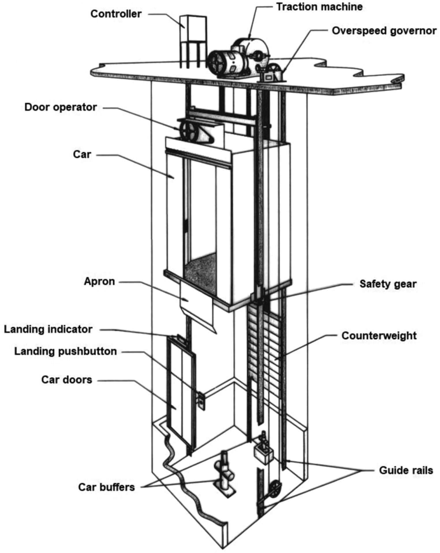
It includes a car, a counterweight, a traction machine, a controller, a counterweight and several safety elements, namely, an overspeed governor – a safety device acting as a stopping mechanism when the elevator car reaches an excessive velocity – a safety gear and buffers (acting as shock absorbers).
Safety is the foremost concern for lifting actuators. 7 Elevator malfunctions may bring inconvenience to the public. Especially for those with disabilities, it may diminish their confidence when utilising this transportation system. 8
Overspeed is particularly hazardous. 7 If the elevator car reaches an overspeed dangerous situation, it may cause severe accidents and damage the equipment. 7 In terms of elevator structural integrity, the worst loading case happens when the elevator car falls freely. 9 In the worst-case scenario, it may cause injuries to the passengers. 7
Therefore, modern elevators must be equipped with safety protection systems to assure safety conditions and avoid accidents, including electrical and mechanical safety elements. One of those safety elements in the elevator’s security is the overspeed governor, which plays an important role. The overspeed governor needs to be verified regularly to check if its performance is reliable. 10
Research about elevator maintenance, especially directing at overspeed governors, is rarely found in the literature. This paper intends to fill this gap. It describes a new overspeed governor velocity measuring system using, among other mechanical and electronic components, a mobile electronic device (smartphone or tablet) processing technology for non-contact velocity measurement. In Ref. 10 , a similar methodology is described. This new process may replace the inaccurate measuring system currently employed by maintenance technicians, thus increasing its reliability.
The structure of the paper is as follows. The Overspeed governor system section briefly refers to the constitution of a generic overspeed governor. The Development section describes the development of a new measuring system able to measure the trigger velocity of an overspeed governor. The Results and discussion section presents the results and discusses them. The Conclusion section resumes the most significant conclusions and points out some improvements.
Overspeed governor system
Regarding the classification of elevators, there is a variety of options, namely, according to the traction type and engine room location. However, and concerning the overspeed governor, this slightly changes.
As a significant part of overspeed and fail-safe protection for elevators, the elevator overspeed governor is a device for limiting overspeed of elevator cars. 11 When an uncontrolled fall occurs during the elevator operation, the overspeed governor will act as a stopping mechanism to avoid any risk to the passenger’s life. 11
An overspeed governor, schematised in Figure 2, is a main elevator safety component
9
that operates when the elevator car velocity exceeds a safety limit value (tripping speed). Scheme of overspeed governor.
9
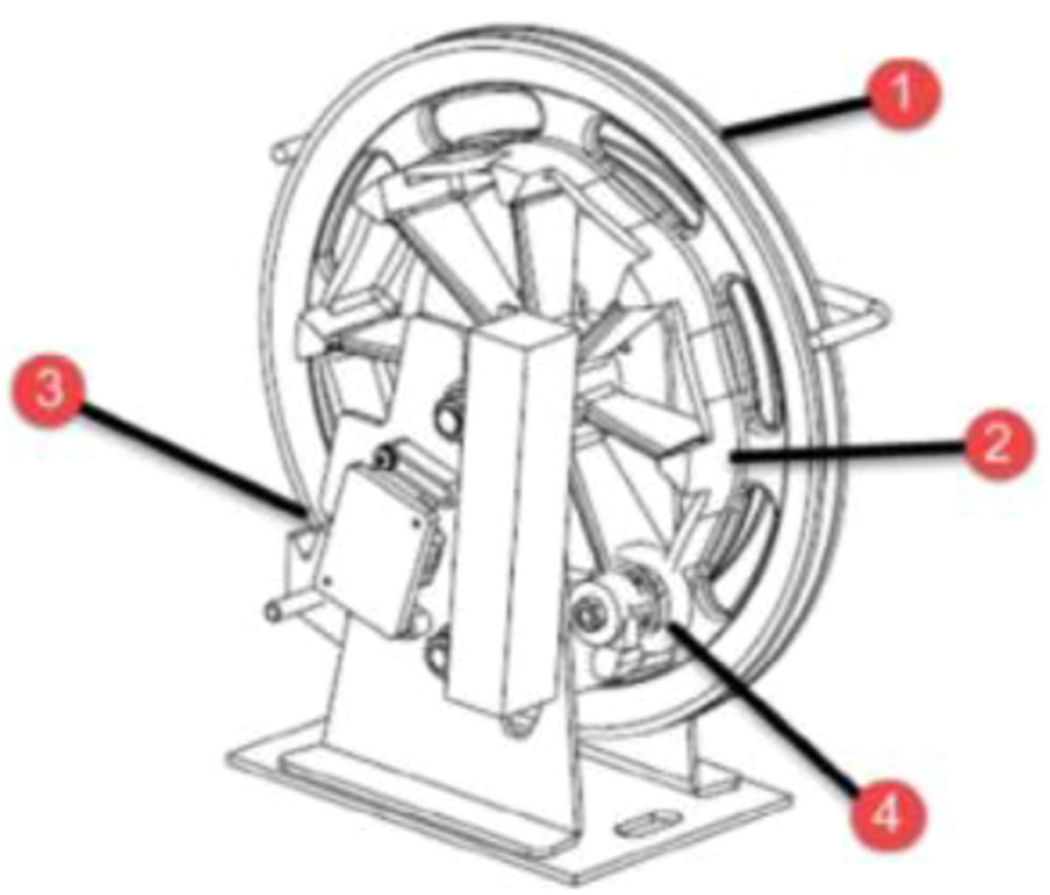
The overspeed governor device is usually a centrifugal system calibrated to a nominal triggering velocity, known as tripping speed. The centrifugal overspeed governor is a crucial safety device in modern elevators, while the centrifugal block plays a critical role in the performance of the overspeed governor. 11 More details about the structure of the centrifugal overspeed governor system may be found in Yunpu (2014). The principal elements are the rope sheave (1), CAM surface (2) and a blocking component (3) activated by the activation wheel (4). 9
A typical overspeed governor system, schematised in Figure 3, comprises the overspeed governor device (1), elevator car (2), safety gear (3), slide catch (4), guide rail (5), governor rope (6) and tensioning device (7).
9
Overspeed governor system.
9
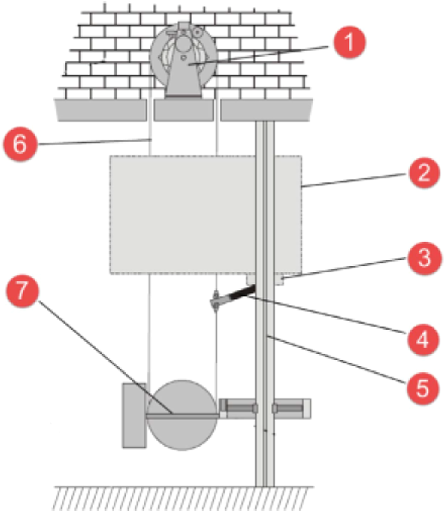
The governor rope (6) connects the overspeed governor (1) to the elevator chassis through a slide catch component (4).
The vertical motion of the elevator car (2) is transformed into a rotational movement of the governor’s sheave through the governor rope (6), animated by the motion of the elevator car (2), thus transmitting that motion to the velocity limiter wheel.
Using a centrifugal system (or an oscillating wheel system) is made a continuous and mechanical comparison of the elevator car (2) velocity with a given tripping speed. The sheave and the governor rope (6) are blocked by the blocking element when the centrifugal force exceeds a specific value. Then, the blocked governor rope triggers the safety gear (3) through a slide catch component (4).
There are two safety gear components in an elevator chassis, one on each side. Since the overspeed governor device is connected only to one of the two safety gear components, the rotational triggering movement is transferred from one slide of the catch component to the other by a rotating shaft. 9
Development
An elevator system is a piece of highly specialised machinery that requires skilled technicians to monitor and keep it safe and reliable. 8 The traditional method for such monitoring depends significantly on regular professional inspections, requiring expensive equipment and trained professionals (Zhang et al., 2018).
Therefore, inadequate maintenance is one of the examples that can generate accidents. The most common practice of elevator inspection depends on human visual inspection, and such a method fails to detect faults that occurred in the system. 8
Overspeed governors are safety devices employed to reduce the risk of accidents. Those accidents may happen due to the excessive velocity elevator cars may eventually reach. They are periodically inspected by certified entities to determine their proper functioning. Those inspections include the measurement of the tripping speed of the overspeed governors. Velocity measurement methods include contact and non-contact measurements. Contact velocity measurements need to be performed with a velocity measuring device contacting directly with the rotating velocity wheel. 10 Additionally, its state of conservation is also assessed.
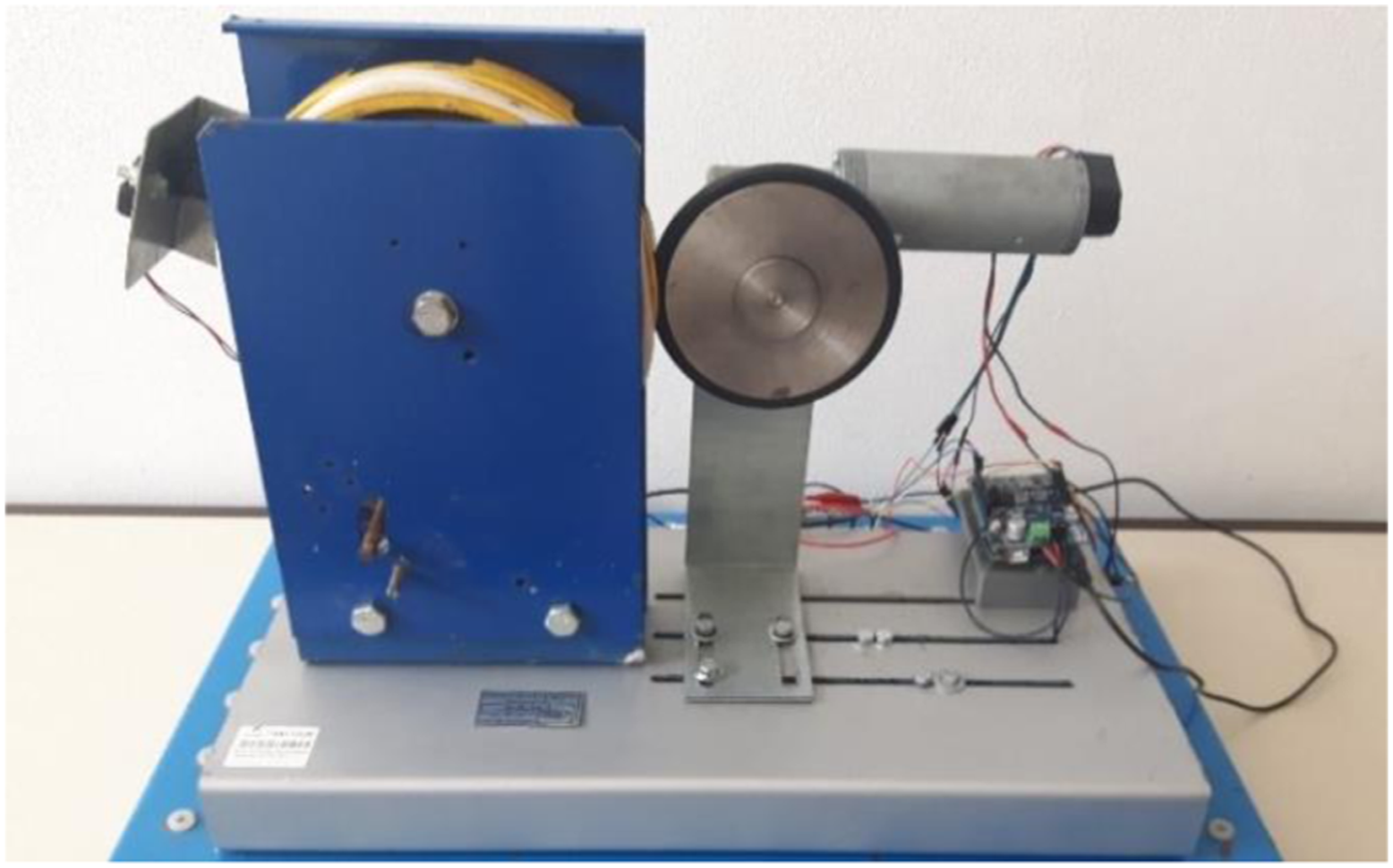
After this brief introduction, the extreme importance of correctly measuring the trigger velocity of the overspeed governor is perceived. However, the method generally used to carry out these inspections is not very rigorous. Additionally, the equipment currently employed for this purpose may not be the most suitable, resorting to the excitation of the overspeed governor wheel and the consequent measurement of its velocity (for example, through a tachometer). Furthermore, the usual procedure places operators very close to the overspeed governor (which is unprotected) during the test, thus not guaranteeing their safety. Moreover, the correct reading of the tripping speed is not guaranteed due to several factors such as: • Difficulty in controlling the velocity that animates the overspeed governor wheel; • An instantaneous spike induced in the overspeed governor wheel may lock it, disallowing the measure of the corresponding tripping speed. Thus, an opportunity for innovation was identified. Figure 4 shows the prototype designed, developed and built of an automatic linear velocity measurement system in overspeed governors. These safety devices should be periodically tested to suitably measure their tripping speed. So, this system will be instaled only on those occasions and not permanently. Its purpose is to test the overspeed governors, correctly measuring the tripping speed. The system can be divided into two components: mechanical and electronic. Prototype of an automatic linear velocity measurement system in overspeed governors.
The main objective is to test the operation of overspeed governors. For this purpose, it uses a combination of innovative mechanical and electronic components, namely, sensors, connected to a data acquisition system. The developed system guarantees the automatic execution of the test under several anomalous operating situations, thus allowing the user to have real-time access to the test data obtained through a graphical interface available on a mobile electronic device (smartphone or tablet).
Mechanical components
The mechanical working principle of this prototype and, consequently, of the velocity measurement system is based on the measurement of the linear velocity of the overspeed governor wheel. It was necessary to develop an assembly capable of moving the overspeed governor wheel used in the prototype. Several hypotheses were addressed: • Use of flexible cable transmission; • Use of flexible V-belt transmission; • Use of contact/friction transmission by an O-ring wheel.
The first two hypotheses were the best, as long as the correct assembly was ensured and the belt or rope did not slip. However, due to the construction of the overspeed governor used in this prototype, they were discarded as they were too complex to assemble (it would be necessary to dismantle the governor to pass the cable or the belt). The last hypothesis trusts on the use of contact transmission through an external wheel. This hypothesis can also give rise to the same slip situation. This problem can be eliminated on the assumption that there is a frictional force between both wheels. Due to the O-ring material, its application overcomes the problem by reducing noise and contacting vibrations between components. Therefore, it is only necessary to lean the O-ring wheel to the overspeed governor wheel, as shown in Figure 5. Overspeed governor wheel (left) contacting with o-ring wheel (right).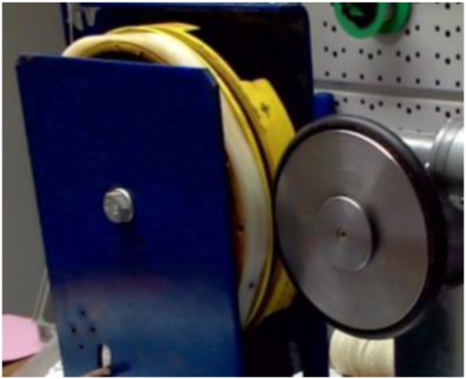
This last hypothesis also contributes to the simplification of the linear velocity calculation. If it is ensured that there is no slip, the linear velocity of the velocity limiter wheel is equal to the O-ring wheel linear velocity.
Electronic components
The prototype includes several electronic components to measure the linear velocity of the wheel with the O-ring, namely: • Electric gear motor for moving the O-ring wheel; • Bluetooth card for communication between the microcontroller board and a mobile electronic device, used as a human–machine interface for communication between the user and the prototype; • Power board (also called H bridge) to control the gear motor (because voltage and current intensity of this component are higher than the one the microcontroller board supports). This electronic component allows, respectively, the control of the gear motor velocity using a pulse with modulation (PWM) output and the gear motor direction of rotation of the with a digital output; • Encoder, mounted on the gear motor shaft, to measure the velocity of the overspeed governor wheel.
Figure 6 shows some of the electronic components already assembled (microcontroller board, power board and Bluetooth board) in a 3D printed support. Notice that the power board is mounted directly on the microcontroller board, so all the connections made on the microcontroller board are transferred to the power board. Thus, a more compact coupling is achieved. Electronic components.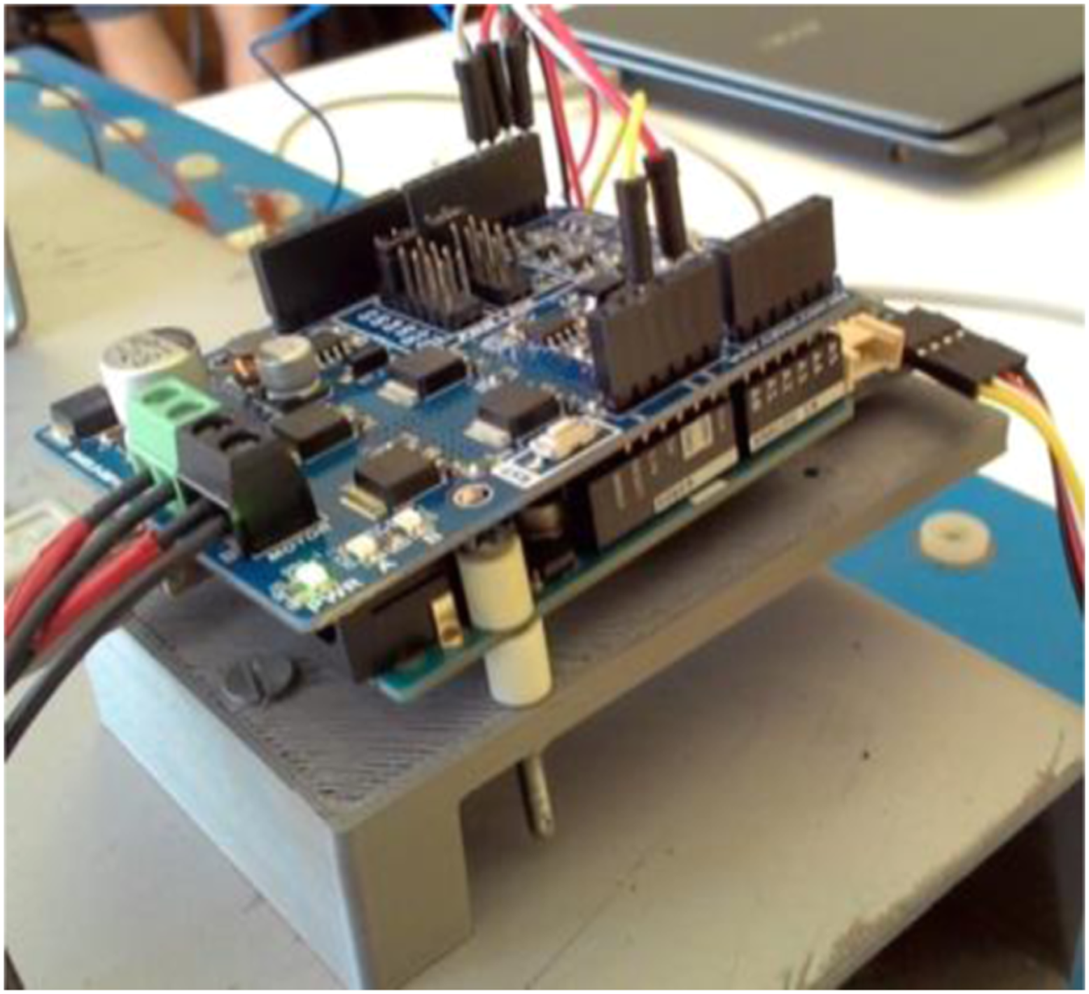
The developed prototype could be the base to build the final version of the system to measure the velocity of overspeed governors.
The main requirements are as follows: • Portability: direct installation of this system on the overspeed governor avoiding the necessity of removing the overspeed governor from the elevator to perform the test; • Compactness: the overspeed governor is difficult to access due to its specific location; • Ease of installation: reduce the test time as much as possible and, therefore, its cost.
From the analysis of the above requirements was designed a final version. Figure 7 shows a three-dimensional (3D) model of the complete system installed in a generic overspeed governor. Final version of the prototype (3D model).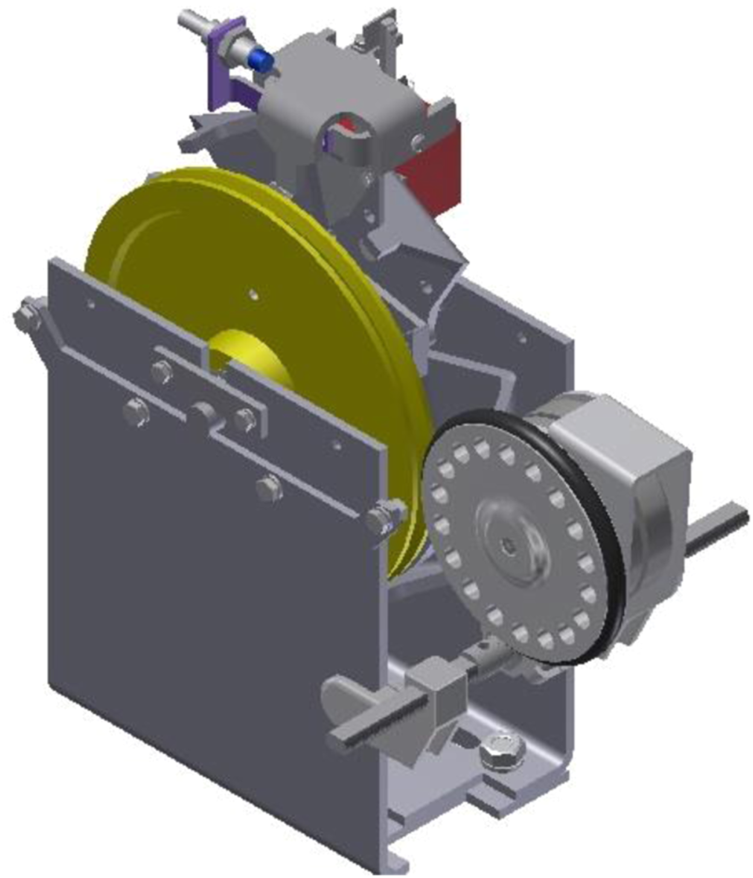
Figure 8 depicts the working principle of the mechanical components of the system. It was designed with the purpose of the O-ring wheel to rotate on a fixed pin with a torsion spring. The torsion spring and the fixed pin ensure that the O-ring wheel touches the overspeed governor wheel and exerts the necessary force. So there is no slip between them. Working principle.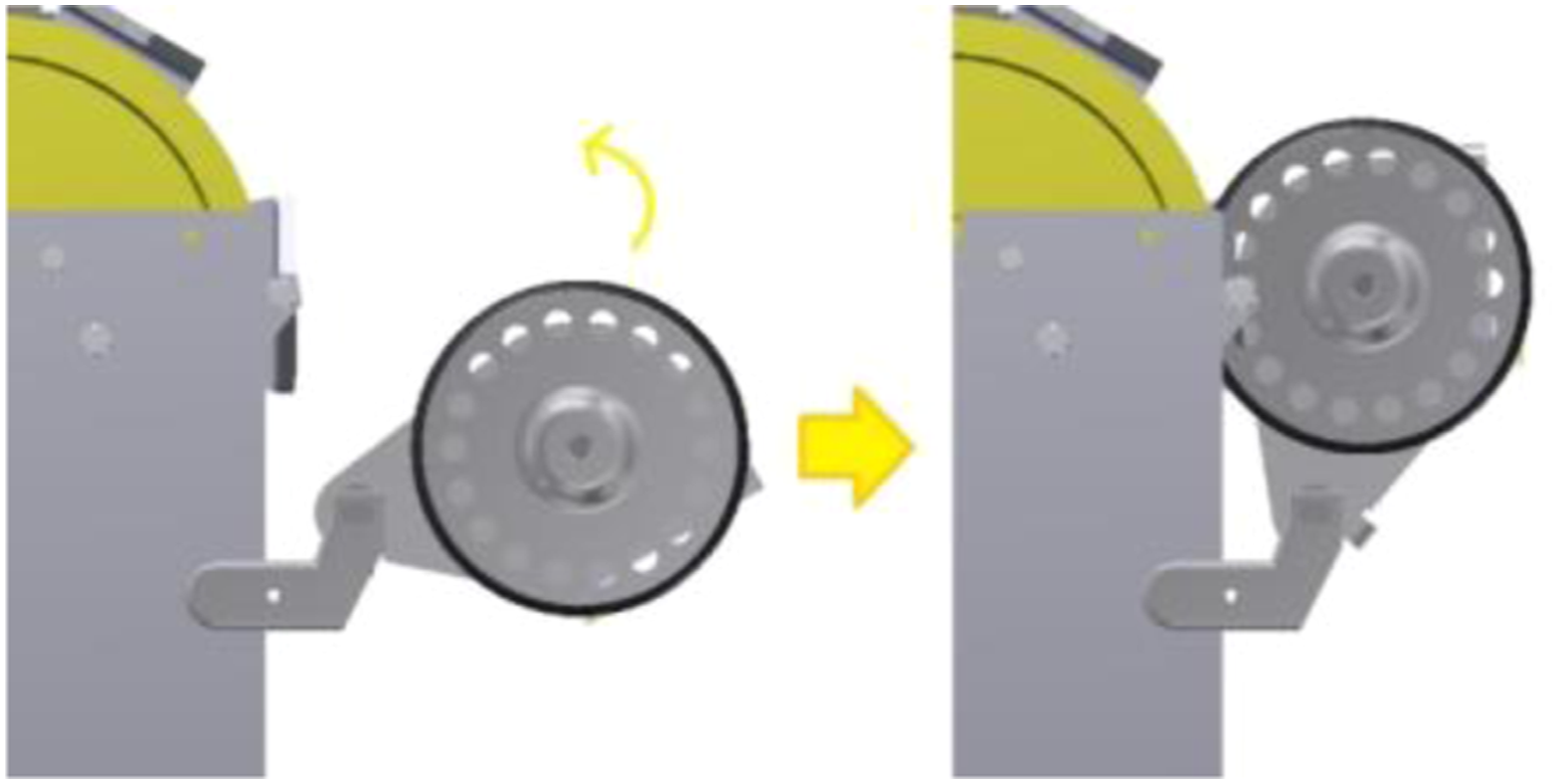
The mechanical components support of the system must include the rotation pin and the connection to the overspeed governor. Thus, the system was designed as shown in Figure 9. Support of the mechanical components of the system.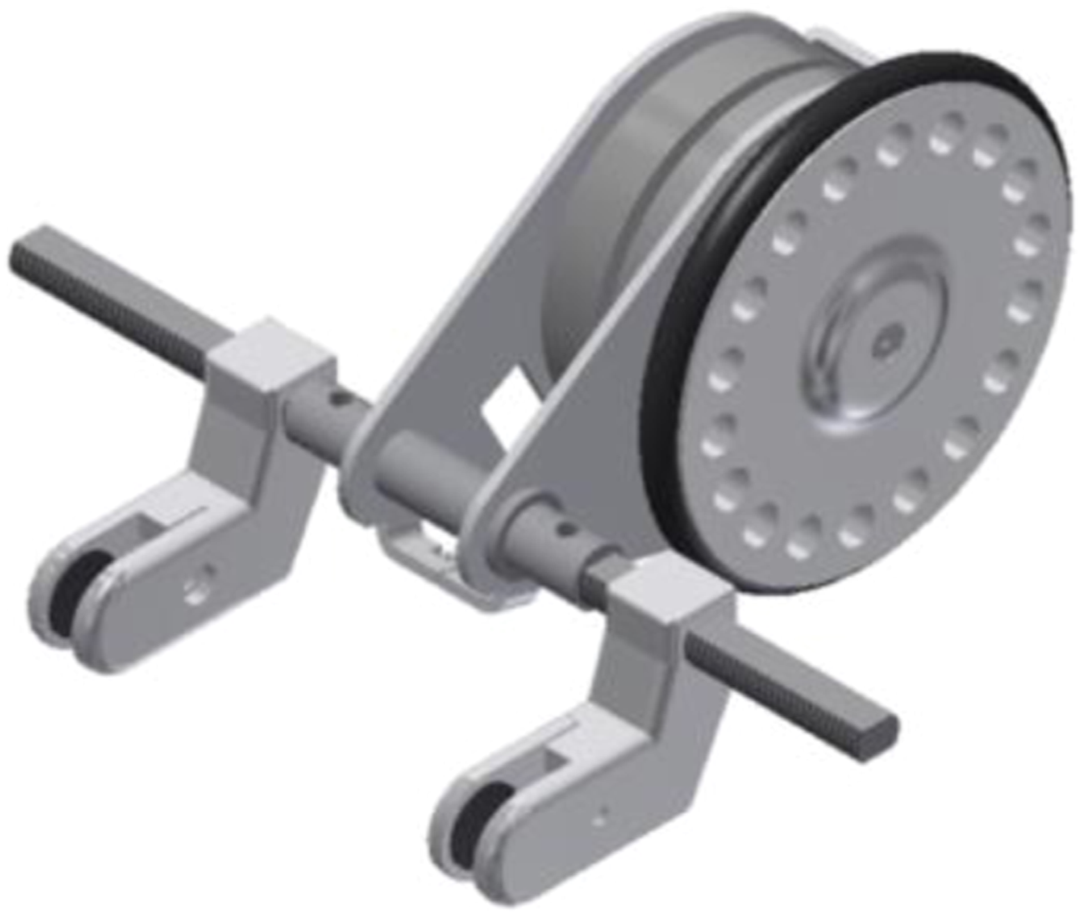
The rotation pin is coupled to two threaded pieces, allowing a longitudinal adjustment. This longitudinal adjustment permits the displacement in both directions, as shown in Figure 10. Longitudinal adjustment.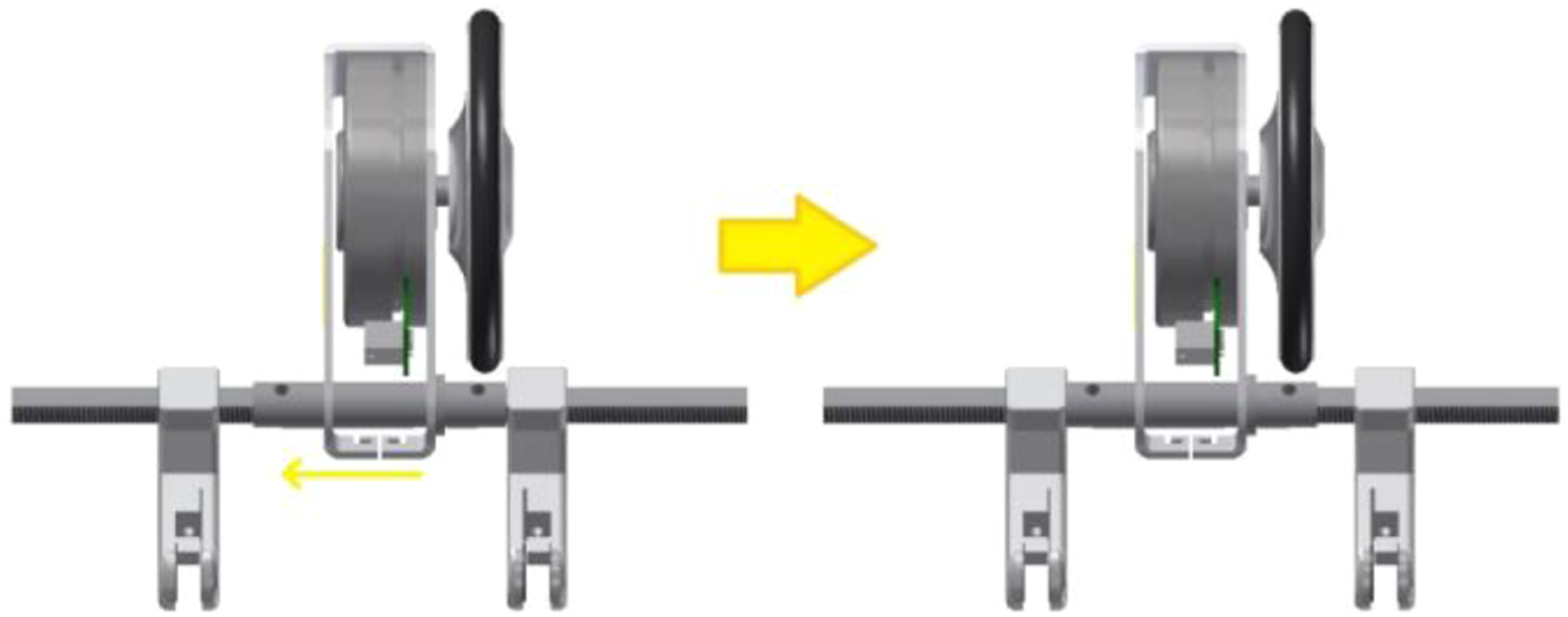
Results and discussion
The system proposed for computing the linear velocity of the overspeed governor wheel is visible in Figure 11. System for calculating the velocity of the overspeed governor wheel.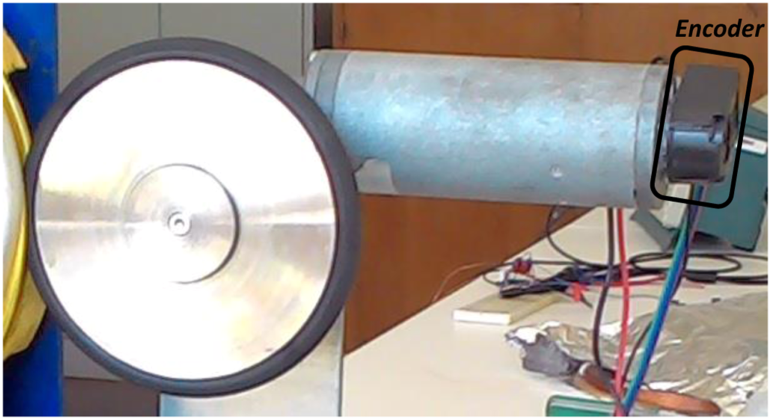
The system designed to obtain the necessary values to calculate the linear velocity includes the O-ring wheel, gear motor and encoder (depicted in Figure 11 on the right).
It is considered the absence of slip between the overspeed governor wheel and O-ring wheel. Consequently, it can be assumed that they both have the same linear velocity. Hence

So it is unnecessary to obtain data related to the overspeed governor wheel (except for the tripping speed defined by the manufacturer). The O-ring wheel linear velocity
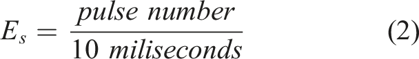
So, to calculate the linear velocity of the O-ring wheel, it is required to define the entire system until it reaches the O-ring wheel. Firstly is necessary to obtain the number of revolutions per second of the O-ring wheel using the encoder signal
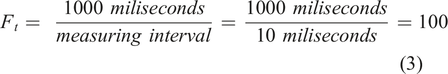
It is also necessary to extrapolate the value of pulses to pulses per second. For this purpose it is calculated previously the time conversion factor F
t
(1 s corresponds to 1000 ms)
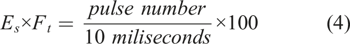
Substituting equation (3) in (2) gives the value of pulses per second
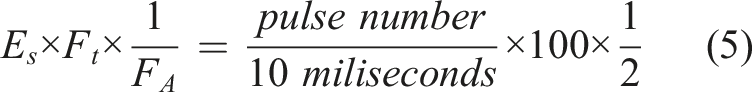
Now is necessary to apply an interrupt conversion factor
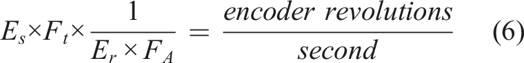
After that, it is necessary to convert this value into revolutions per second. To do so is given the encoder resolution
From Figure 11, the gear motor also influences this calculation. Gear motors have a gear ratio (also known as reduction ratio). If the encoder registers x revolutions and the motor has a gear ratio of x:1, then the O-ring wheel has only rotated one revolution and not x revolutions registered by the encoder. Hence, the gear motor reduction factor
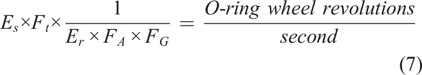
Finally, it is necessary to convert the value of revolutions per second into a linear velocity
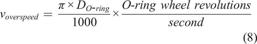

A graphical interface application, developed for mobile electronic devices resorting to the App Inventor 12 open-source software, helps the user interact with the prototype and obtain, in real-time, the time function graphic of the linear velocity. The code developed and downloaded to a mobile electronic device includes the above calculation methodology.
Part of the code is also dedicated to the gear motor velocity control. Additionally, four control maps were made: • Test considering a scenario in which the elevator is submitted to a linear and slow slide; • Test considering a scenario in which the elevator is submitted to an uncontrolled free fall; • Release the overspeed governor after the test; • Turn off the electric gear motor.
An elevator has two essential velocities: nominal velocity – also known as rated speed – and tripping speed. The last is always depends on rated speed. Hence, the overspeed governor should be selected knowing in advance the rated speed.
Under Portuguese legislation, elevators must comply with several regulations. According to Decree-Law 58/2017, which transposes the European Directive 2014/33/EU, elevators must be equipped with an overspeed governor device. Decree-Law 513/70 promulgated the Electric Elevator Safety Regulation. According to Article 67, the car overspeed governor shall operate before the ratio between the increase in the descent car velocity and the rated speed reaches a given value. For instance, for a rated speed between 0.70 m/s and 1.50 m/s, the tripping speed cannot surpass 40% of the rated speed. 13
A landslide scenario was tested, assuming a rated speed of 1 m/s. Therefore, the tripping speed which triggers the tested overspeed governor should never exceed 1.4 m/s (40% above the rated speed).
Figure 12 depicts the technical data of the overspeed governor used, showing the tripping speed of 1.4 m/s. Overspeed governor technical data.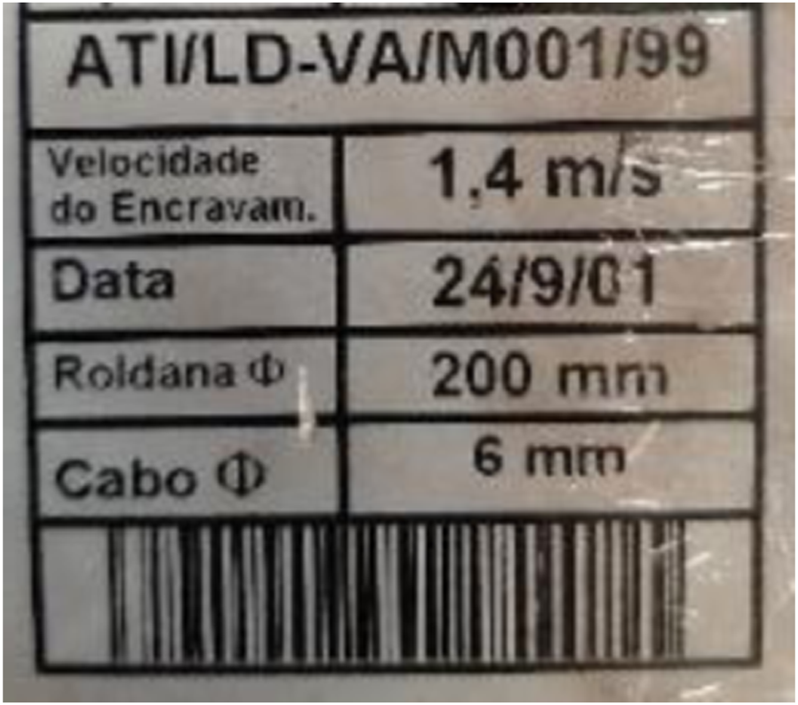
Figure 13 depicts the final report obtained after the test. The result shows that the measured velocity is 1.42 m/s, slightly higher (14,3%) than the maximum admitted value (1.4 m/s). Thus, the overspeed governor is not working correctly. Final report obtained after a landslide scenario.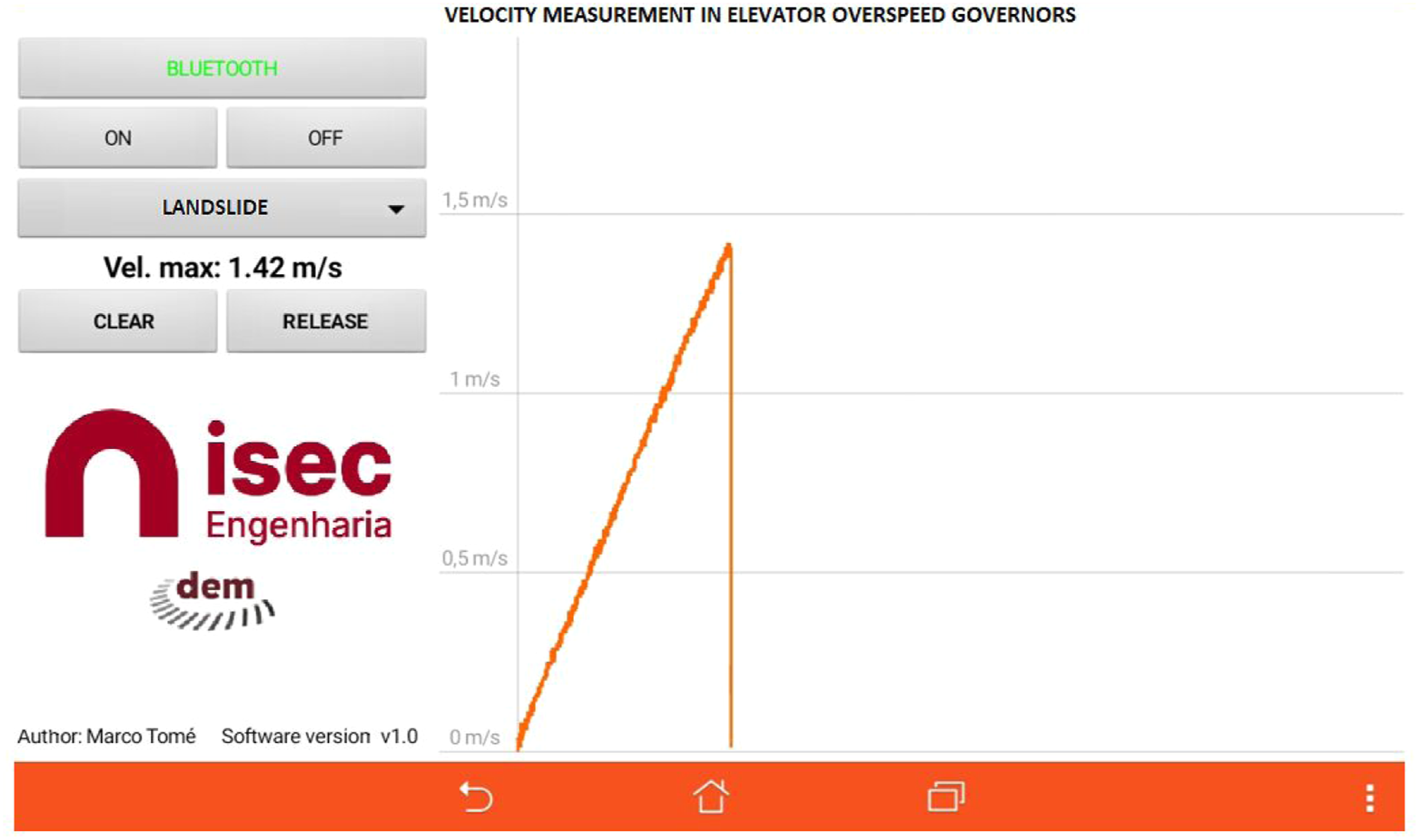
Conclusions
According to the Portuguese General Regulation for Urban Construction (RGEU), buildings with more than three floors require the installation of elevators. 14 However, tall buildings are very scarce in Portugal. For that reason, the prototype was devised to test typical electric traction elevators mainly applied to Portuguese habitational buildings.
Typical electric traction elevators include a car balanced by a counterweight and suspended by a grip-driven steel rope through a rope wheel. This wheel is driven by a speed reducer coupled with an electric motor. Instead, in high-speed elevators (above 2.5 m/s), the rope wheel is driven directly by a low-speed motor (gearless). Therefore, high-speed elevators present some particularities that are yet to be studied. Thus, its compatibility with the developed system has yet to be verified. For that reason, they are outside the scope of this study.
The main concern of this invention was the rigorous determination of the linear velocity of an elevator overspeed governor. The concept of the developed device – compact, portable and easy to attach (due to the difficult to access places where overspeed governors are usually installed) – allows its direct installation in the overspeed governor, thus avoiding the withdrawal from the operating place to test it. It is also worth mentioning the possibility of adapting this innovative system to most existing overspeed governors.
Some improvements can also be made in the final version of the system for measuring the velocity of overspeed governors.
Concerning the programming code, both in microcontroller board and in the mobile electronic device, it will be possible to solve some errors that may persist and improve the graphical interface, introducing new features such as: • Include new test maps; • Include maps to allow testing in both directions of rotation (testing the elevator descent/rise as there are overspeed governors that work in both directions); • Prepare reports that could be sent automatically to the entity responsible for the tests and to the certifying entity of the elevator (streamlining the whole bureaucratic process); • Incorporate, in the mobile electronic device program, a tutorial regarding the installation of the system in the different models of overspeed governors installed on the elevators; • Create, in the mobile electronic device program, a database with overspeed governor characteristics (thus, the overspeed governor is approved/disapproved without operator intervention, avoiding reading errors).
Measuring errors inherent to the mechanical component of the system can also be reduced, for example: • Insert a coefficient reflecting the force applied between the contacting wheels (obtained by the torsion spring), which could affect the obtained velocity; • The electric gear motor must have a reduction ratio as efficient as possible or even no reduction (eliminating possible errors due to clearances between the gear and O-ring wheel).
Footnotes
Declaration of conflicting interests
The author(s) declared no potential conflicts of interest with respect to the research, authorship, and/or publication of this article.
Funding
The author(s) received no financial support for the research, authorship, and/or publication of this article.