
Abstract
In its simplest form, a Closed Cavity Façade (CCF) consists of a double or triple glazing unit (DGU or TGU) on the inner layer and single glazing on the outer one, forming a sealed non-ventilated cavity with an automated shading device in between. Given its dynamic behaviour, this technology can dynamically control the flow of solar energy and light penetrating the building. Using EnergyPlus and IDA ICE, several CCF configurations were investigated and compared to the baseline (TGU). MATELab, an office-like test facility at the University of Cambridge, was used as the model, which was beforehand experimentally validated. The results show extensive benefits of CCFs compared to traditional TGU systems, in terms of thermal performance and occupants’ comfort. The CCF configurations investigated led to an improvement of energy performance in the range of 18–37% compared to the traditional TGU, depending on the CCF configuration and the climate while a previous study, using CCF configurations with DGU as inner skin, revealed an improvement of energy performance in the range of 22–41% compared to the conventional DGU. Further investigation showed that glass coatings and solar shading characteristics play an important role in cutting down overheating phenomenon while increasing occupants’ comfort.
Introduction
Buildings are at the pivotal centre of our lives. We spend, on average, 87–90% of our time in buildings. 1 The characteristics of a building, its design, its look and feel and its technical features influence our productivity, well-being, interactions with others, and they also define how much energy is consumed in and by a building, particularly for heating, ventilation, cooling and lighting. The increasing trend of urbanisation leads to a greater density of people near transport hubs, in the central areas of cities, living in buildings with limited space and higher occupant load. Hence, building façades are required to provide an increasing level of thermal, visual and acoustic comfort for building occupants and to have the ability to interact with the external environment through the greater use of natural daylight and ventilation. In this regard, the building ‘skin’, as human skin is an all-important barrier and thermal regulator of the human body, is the first critical element in defining goals for building energy performance and occupant comfort.
Buildings consume considerable amounts of energy to maintain comfortable indoor conditions. Buildings and the building construction sector combined are responsible for 36% of global total end-use energy consumption, whereas in some developed countries, this sector is responsible for up to 40% of the total energy consumption. 2 Particularly, the building sector in the EU is the largest single energy consumer in Europe, absorbing 40% of final energy, whereas about 75% of buildings are energy inefficient. 3 Due to this, on the 17th of April 2018, the European Parliament gave its final approval on the revised Energy Performance of Buildings Directive. This approval signals the closure of the first of eight legislative proposals part of the ‘Clean Energy for All Europeans’ package brought forward by the European Commission on the 30th of November 2016. This package is a key element of one of the EU priorities, ‘the climate change policy’. Through this policy, the EU aims to make new and existing buildings smarter and more energy-efficient, and ultimately to cut CO2 emissions by at least 40% by 2030 while each State Member must follow the path towards a low and zero-emission building stock by 2050. 3
Since glazing and windows are essential components of building envelopes, which provide daylighting, vision, air ventilation and passive solar gain, their contribution to the total energy consumption of buildings has been repeatedly investigated. 4 Glazing is particularly critical because it is the most vulnerable envelope part to heat gain and heat loss. It is often considered as a large thermal bridge at the building envelope with high thermal losses. Consequently, the building envelope, and in particular, the glazed openings play a significant role in the building energy consumption. In this regard, about 50% of the energy loss in buildings is attributed to glazing.5, 6 Therefore, the glazed openings require detailed design and proper selection to provide the highest possible thermal and visual comfort with the lowest possible operational energy demand. With the rapid development of various glazing technologies, knowledge of their properties and characteristics is essential for deploying them in different climates to enhance energy saving and occupants’ comfort. It is a fact that in recent years, the window performance has been improved significantly through different window and glazing technologies, such as multi-layered glazing and the use of several types of coatings, which in general make windows more energy-efficient. 7 However, conventional glazing technologies have relatively poor performance characteristics which cause significant heat losses during winter and undesired heat gain in summer. Hence, during the last two decades, sustainable building design is rapidly moving towards a design approach aiming to design innovative high-performance façade systems able to provide high thermal insulation and react to outdoor environment and occupants’ requirements to reduce building energy demands and enhance thermal and visual comfort7,8 with a proven increase in productivity. 9 Such an innovative adaptive façade technology, the Closed Cavity Façade (CCF) of various configurations has been studied in this work emphasising its thermal, visual and comfort performance, for various types of climates, compared to the traditional triple glazing unit (TGU).
From Double Skin Façade (DSF) to Closed Cavity Façade (CCF)
In contemporary glass office buildings with window-to-wall ratio (WWR) often around 80% for maximising views and daylight, innovative façade systems compared to traditional technologies are required to reduce energy demands and meet occupants’ comfort requirements imposed by the increasingly stringent codes. A milestone, during the last decade of the previous century, was the development of the DoubleSkinFaçade (DSF) (Figure 1) which was used mainly in commercial and high-rise buildings. Basic assembly components of double skin façade.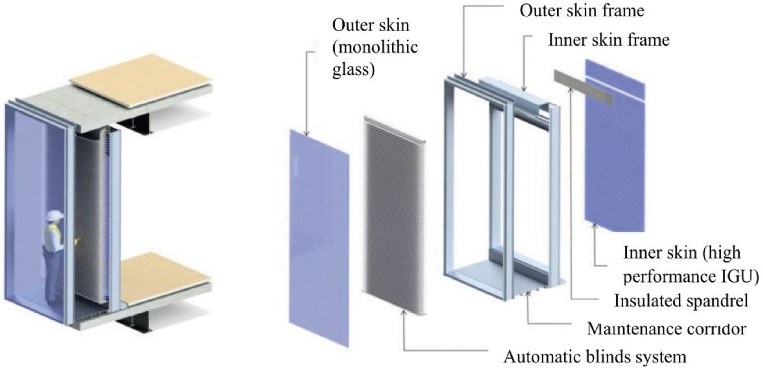
DSFs can help to meet the requirements due to their improved thermal performance and integrated solar shading system having been primarily used in cold and temperate climates, although there are some examples in warmer climate types. Double skin facades (DSFs) are a specific type of building facades, aimed to improve thermal performance of glazed envelopes. DSFs consist of three distinct layers: interior glazed system, ventilated air cavity, and exterior glazed system. The ventilated air cavity serves as a thermal buffer between the interior and exterior glazed systems. Basic types of DSFs are box window, corridor façades, shaft box façades and multi-story façades.
10
There are five ventilation modes of the air cavity as shown and explained in Figure 2 and ventilation type can include natural, mechanical and mixed ventilation. Ventilated and unventilated double-skin glass façade schematic configurations: (a) Externally ventilated DSF, (b) Internally ventilated DSF, (c) Internally ventilated DSF with cavity downdraft, (d) Breathable DSF and (e) Pressurized DSF (CCF) (retrieved from
11
).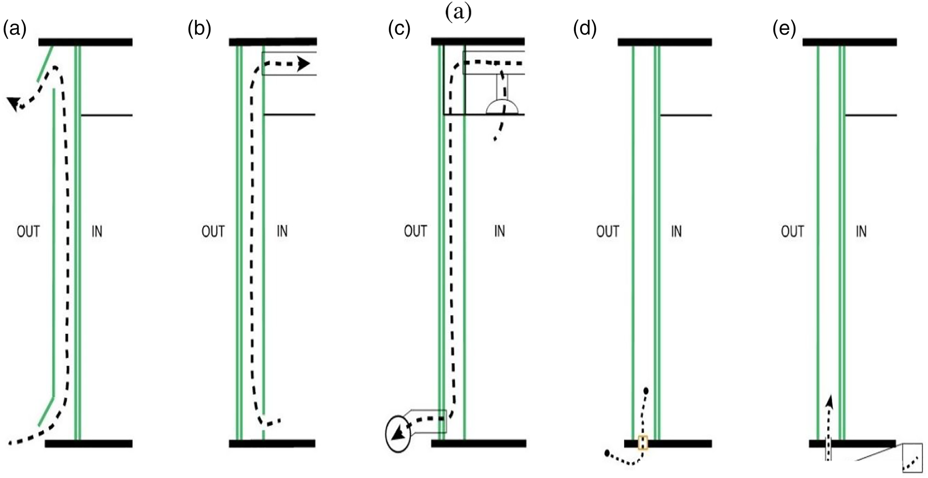
In the externally ventilated DSF (Figure 2(a)), an outside air stream introduced and passing between the two glazed skins plays the significant role of evacuating excess heat and humidity reducing the risk for condensation formation on any of the surfaces. This type of double skin façades is found with various glazing, cavity depth and ventilation openings. Many have openings in the inner skin permitting natural ventilation of interior spaces while some are designed to draw warm air from the cavity contributing to space heating and thus, reducing the heating energy consumption.
In the internally ventilated DSF (Figure 2(b)), the air space between the two skins plays the role of a return air plenum. Conditioned room air is drawn between the two glazed skins where a constantly refreshed thermal buffer against heat gain/losses through the facade is created and the cavity air returns to the space providing energy recovery. While the airflow in an internally ventilated facade can be upwards (Figure 2(b)), it could also be downwards as shown in Figure 2(c).
The last two DSF innovations do not feature pass-through cavity ventilation (Figures 2(d) and (e)). In the breathable DSF (Figure 2(d)), the double-skin air space communicates with the exterior environment through small, filtered openings in the lower frame area. This technique allows vapour pressures to balance between the air space and the exterior environment preventing condensation in the cavity. In the innovative new pressurised façade double-skin technology (Figure 2(e)), called Closed Cavity Facade (CCF), a pressurised supply of filtered and dry air is continuously fed through tiny tubes in the modular unit frames to sealed air space. 11 The dry air, supplied in very small quantities based on external climate conditions, prevents condensation in the air space. Furthermore, because dust and other contaminants are not brought into the double skin air space, the need to clean the cavity is eliminated.
There are several applications of DSFs across the world, which along with significant research available 10,12,13,14,15 relating to the thermal and energy performance of DSFs have proven that DSFs present many advantages compared to traditional glazing systems. Such advantages include improvement of acoustic and thermal insulation and therefore decrease of heating loads, improvement of thermal comfort, the possibility of positioning solar control and lighting devices in the cavity and apply night-time ventilation during the cooling period, reduction of cooling loads due to the presence of dynamic blinds in the cavity, etc.16,17 However, a few limitations impede the deployment of DSFs in a greater number of buildings. Such limitations include the higher necessary investment and higher cost for maintenance and cleaning connected to DSFs, the higher embodied carbon/embodied energy needed through their life cycle, the loss of useful building space due to the wide corridor needed, the extra cost introduced by the introduction of internal openings required as access from the inside for cleaning and maintenance purpose, the risk of condensation on the interstitial glass surfaces between the two skins, 18 etc.
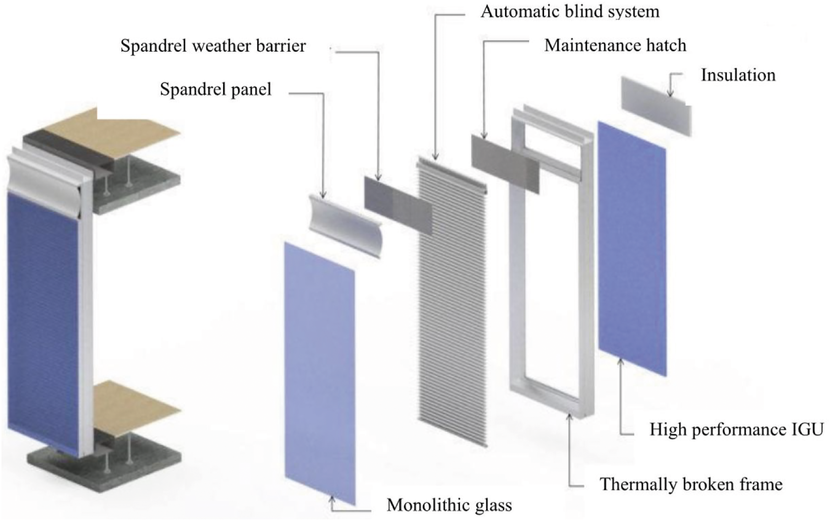
The above limitations, and particularly the ones regarding the loss of useful building space and the higher investment, maintenance and cleaning costs connected to DSFs led to the search for other solutions. A solution for extremely demanding building envelopes with the best properties for insulation and sun protection was still missing until the end of the first decade of this century where a new idea for a DSF type, called Closed Cavity Façade (CCF), was devised. It consists of a double or triple insulated glazing unit on the inner layer and single glazing on the outer (Figure 3), forming a cavity (typically between 100-250 mm) with a fabric roller blind or a Venetian blind in between. The basic assembly components of CCF are schematically shown in Figure 4. CCFs present different functional and operational advantages as compared to DSFs, such as preventing accumulation and settlement of dust and particles in the cavity, reducing maintenance cost, eliminating the complexity of the airflow control, and increasing the service life of components inside the cavity,
19
etc. Rather than ventilating the double skin, the panels are sealed and equipped with a pressurised supply of filtered and dehumidified air which supplies dry air in the sealed cavity to control cavity pressure, suppress condensation and avoid heat build-up inside the cavity. Schematic of CCF consisting of DGU or TGU on the inner layer and single skin on the outer with a Venetian blind (occasionally a roller blind) in between and the DGU or TGU as the reference glazing. Basic assembly components of closed cavity façade.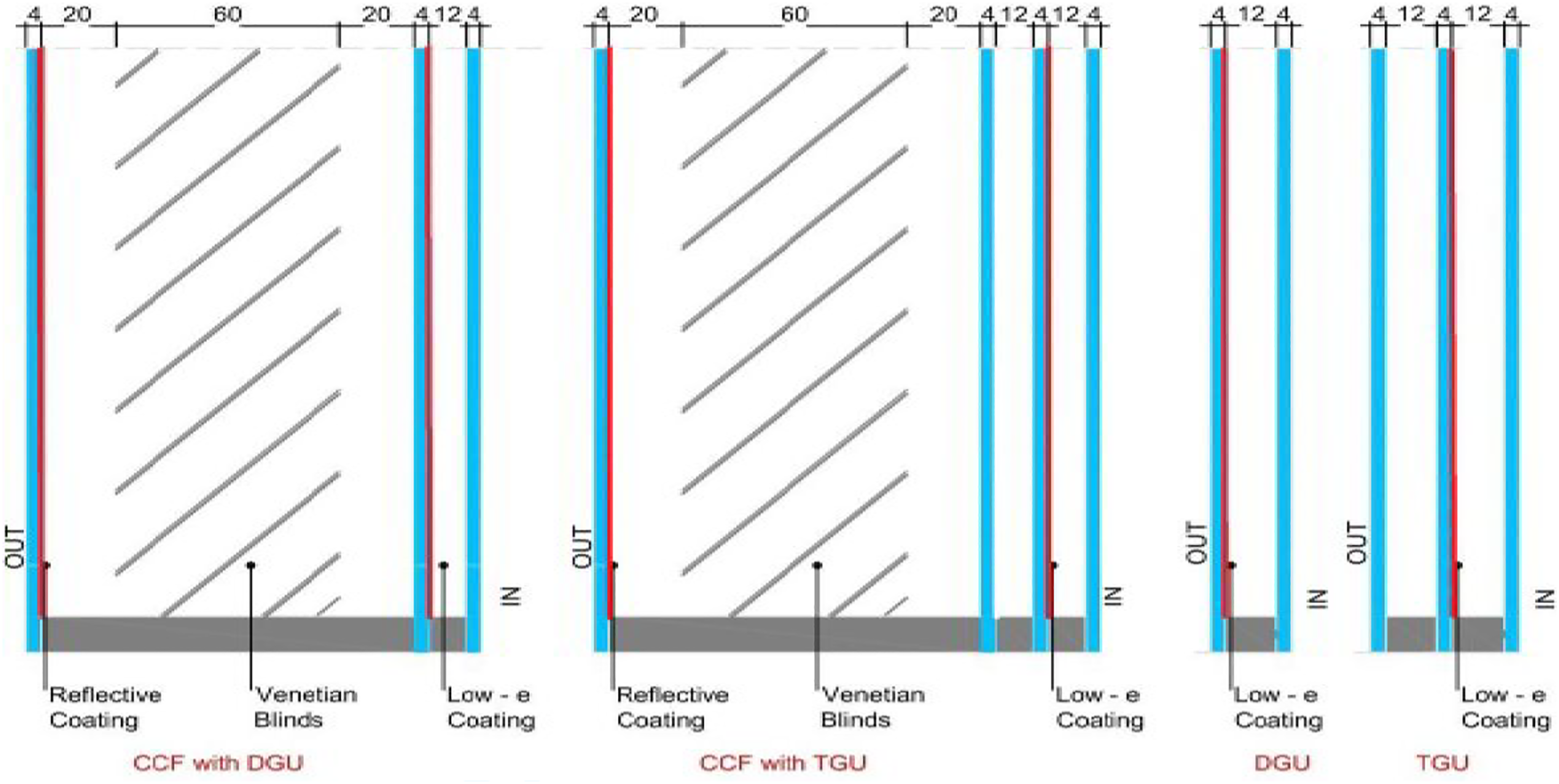
Compared to a conventional externally or internally ventilated DSF, which typically requires around 600 mm distance between glass skins for maintenance, the theoretical thickness of a CCF is 130–150 mm, whereas in practice this is approximately 200–250 mm. 19 This significant advantage of the CCF results in less required useful building space for the façade while allowing its prefabrication and consequentially reducing the manufacturing and installation cost.
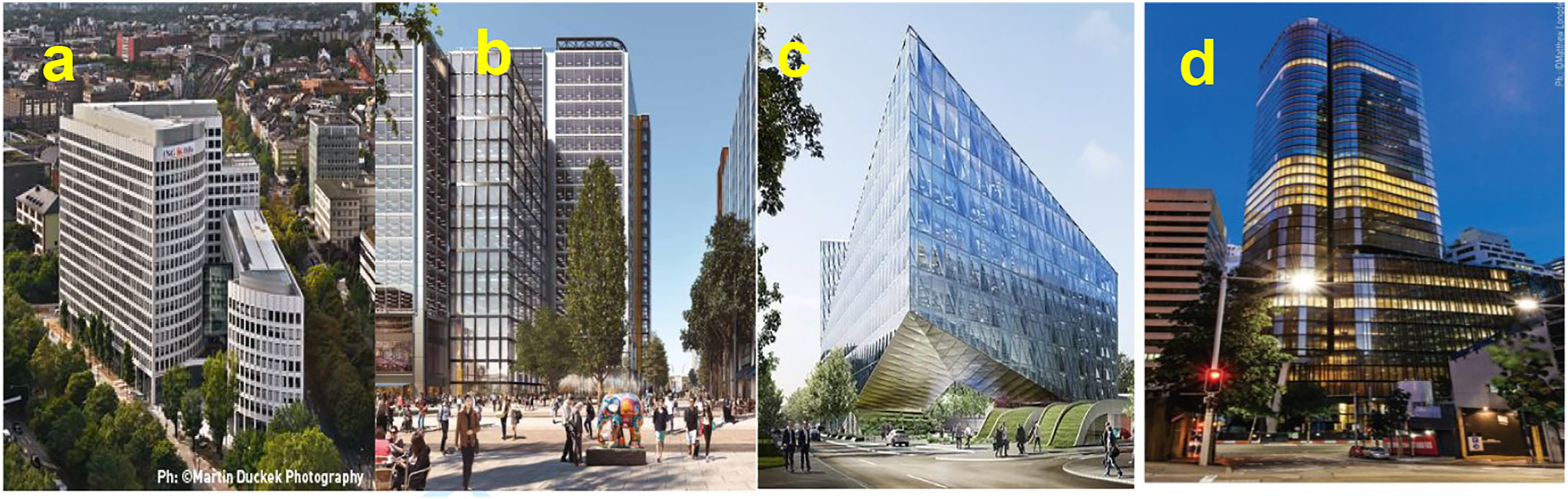
CCF is a relatively recent development in the market of glazing façade technologies with the first buildings being completed at the starting of the second decade of the 21st century. For example, the CCF technology MMFree-S (moisture/maintenance-free sustainable) during the last decade was developed and employed in important realisations in Europe, Asia and Australia. Such projects include (Figure 5): (a) The LEO Building in Frankfurt completed in 2013 (10,000 m2 CCF) being the first full-scale CCF application in Germany and first-ever CCF with operable windows;
20
(b) The International Quarter London which is expected to be completed in 2025 (23,000 m2 CCF) with CCF and BMS-controlled parallel-opening windows;
21
(c) The new Japan Tobacco International (JTI) Head Quarters in Geneva, Switzerland, completed in 2015 (18,500 m2 CCF)
22
and (d) The 200 George St, Sydney, Australia completed in 2014 ((20,000 m2 CCF) and being the first CCF application in Australia and first-ever integration of wood solar protection in the CCF air space .
23
Literature review of Closed Cavity Façades
Since CCF is a relatively recent development in the market of glazing façade technology, there are only a few research papers that investigate the main features, performance, benefits and limitations of this façade system. Particularly, studies that systematically investigate thermal and energy performance of CCFs in all types of climates currently do not exist. Moreover, studies that also investigate different configurations of CCFs and their thermal and energy performance are currently very limited. Therefore, this section reviews relative available literature (more for cold-temperate climates and less for warm cooling-dominated ones) and the key findings of previous studies are summarised below: 1. CCFs have been employed, proving their efficiency in terms of thermal and visual performance, and increasing indoor environment quality, in several projects in northern Europe characterised by cold-temperate climate, whereas only a few projects applied this type of double skin façade system in a warm climate, such as Australia, due to concerns about cavity overheating and the effectiveness of the whole system in cooling-dominated climates.19,23,24,25 2. Previous research showed that, in colder seasons, the cavity temperature in DSFs increases compared to the exterior temperatures, but particularly during the hot summer seasons the cavity temperature reaches critical values. Although for DSFs, heat build-up in the cavity is a common phenomenon, in a CCF system this phenomenon is more pronounced due to the lack of ventilation. In this regard, it has been highlighted that in warm climates (with average summer temperatures above 25°C), the cavity temperature can significantly increase.
25
3. Although in warm-hot climates, the overheating in the DSFs’ cavity is a phenomenon that needs serious consideration, previous studies show that, for cooling-dominated climates, the cooling energy consumption can be on average decreased by 15% compared to conventional DGUs with internal blinds. Furthermore, the DSFs’ performance can be further enhanced if proper coatings and shading means be suitably selected and applied.16,17,26 4. Additional to the enhancement of building energy efficiency, another important benefit of CCFs is that, during the winter season, they result in higher interior surface temperatures due to their lower U-value, ultimately leading to a significant reduction in occupants’ discomfort near the perimeter. In this regard, it is possible to reduce the percentage of people dissatisfied (PPD) by up to 40% compared to PPD with DGUs. Despite this benefit, in warm climates during hot summer seasons, careful assessment of the potential impact of overheating that can be developed in the cavity of the CCF is needed. The heat that is absorbed by the integrated blinds and other components of the system is trapped in the cavity and then is irradiated into space, consequently leading to the interior surface’s temperature increase. Ultimately this phenomenon causes an increase of radiant discomfort and a significant rise of the PPD. A previous study for Singapore, with a typical tropical climate, showed that the replacement of DGUs with DSFs resulted in a decrease of PPD by 18% and 21% for the winter and summer seasons, respectively.11,24,27,28 5. Further to the energy efficiency and comfort aspects, another important aspect needed to be investigated, at the initial design stage of CCF implementation in warm climates, is the maximum temperature that may be developed in the cavity ensuring that this will be less than the maximum recommended working temperature of all the system’s components such as glass seal and silicones, blinds and blind’s slats etc.19,27,28 6. A recent study investigating the thermal performance of CCFs in California climates revealed extensive benefits of CCF compared to conventional DGUs in terms of energy performance and comfort. It was shown that all the investigated CCF configurations enhance the energy performance due to the improved U-value and integrated Venetian blinds in the cavity. It was noted that the degree of improvement depends on the climate (higher in warm mild climates compared to hot and arid ones). Furthermore, it was shown that the proper selection of CCF components such as coatings and blinds colour play a significant role and considerably affect the performance of the façade and its longevity. Thus, for maintaining the temperatures in the cavity below the critical value of 80–90 °C for hot climates, light colour blinds with reflectance above 50–60% and double coating (a hard coating on the external skin and a low-e coating in the internal) are recommended.19,29,30
As previously mentioned, there is a lack of studies that systematically investigate the performance of different configurations of CCFs in various types of climates. Thus, the main objective of this work is to investigate, for different types of climates, the thermal, visual and occupants’ comfort performance of various configurations of CCFs with triple glazing unit (TGU) as inner skin and compare them to the results of a previous study performed by the authors using DGU as inner skin. 29
Assessment of the potential impact of using CCF, with TGU as inner skin, in office buildings
Method
To address the main question of this study, ‘what is the potential impact of using CCFs, with TGU as inner skin, in enhancing building thermal and comfort performance in office buildings’, several CCF configurations and materials were investigated and compared to the baseline – a conventional TGU. Various simulation tools (WINDOW 7.7, EnergyPlus 9.4.0 and IDA ICE 4.9.9) were used to build up the CCFs configurations and simulate their indoor climate and energy performance for various climates using as simulating model the MATELab, an office-like test facility at the University of Cambridge. The three main steps of the threefold method used are meticulously described in the following sub-sections.
Closed Cavity Façade configurations build-up
Aiming to investigate the performance of CCFs for various locations-climates, a set of different configurations has been built up. Various types of glass panes, with or without coatings applied, and two types of integrated Venetian blinds as shading devices were considered. The glass pane of the outer skin and the outer panes of the TGU are of 4 mm thickness, whereas the innermost pane is tempered of 6 mm thickness due to safety considerations. The various CCF configurations are grouped into three groups, namely, CCFT 1, CCFT 2 and CCFT 3 for which schematic details are shown in Figure 6. The three groups of CCFs configurations simulated.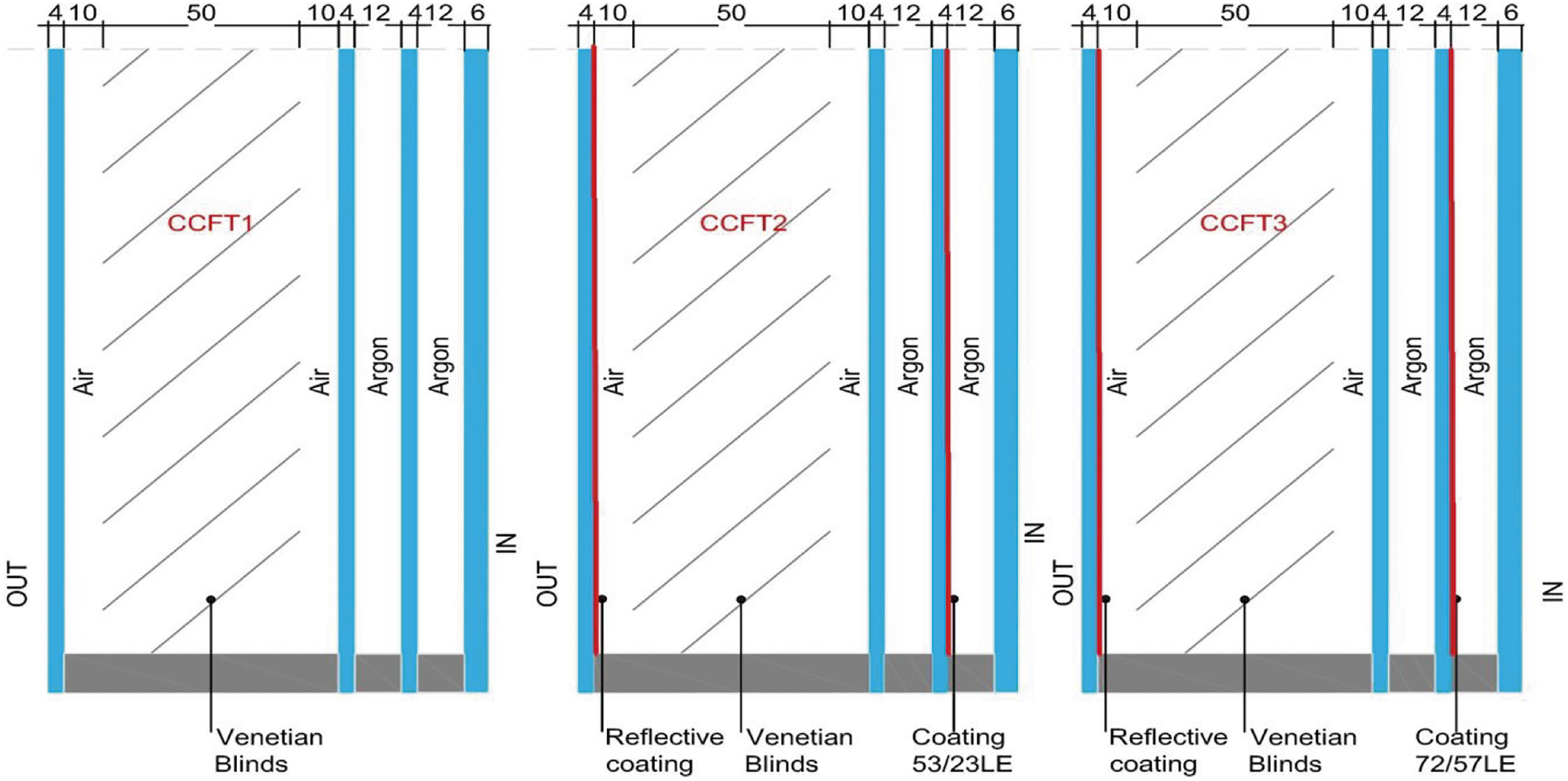
Performance values of CCF glazing configurations simulated.
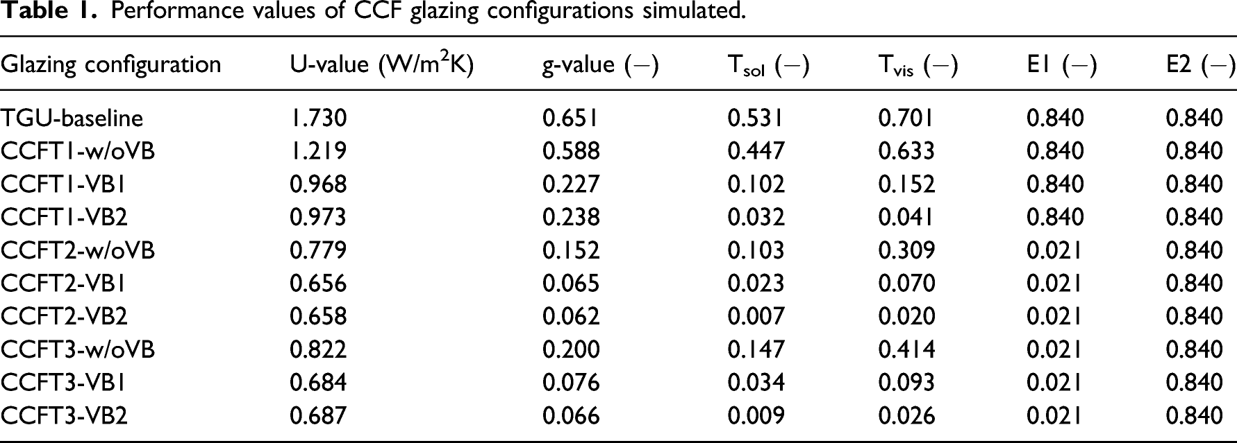
For the assessment of the CCF configurations in comparison with a baseline TGU, the values of Table 1 are inserted into the EnergyPlus and IDA ICE simulation programs. The integrated Venetian blinds are fully retracted when the incident radiation level on the façade is smaller than 250 W/m2 while when this threshold is reached the blinds automatically are fully deployed.
Locations and climate classes
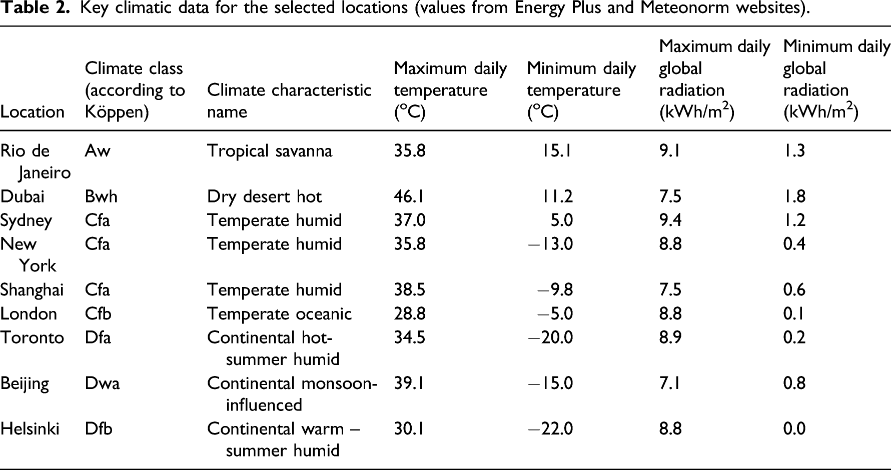
The locations selected to be used for this comparative study comprise cities of different weather characteristics that have building markets with significant potential for high-rise office buildings, where CCFs can be implemented. Aiming to investigate the performance of the CCF technology for different Köppen climate classes, nine cities were selected. Table 2 shows the maximum and minimum daily temperatures and global radiation for each location-climate from which the significant differences in terms of temperature are highlighted.
Key climatic data for the selected locations (values from Energy Plus and Meteonorm websites).
Modelling and performance simulation of CCF configurations
Indoor climate and energy modelling was performed in EnergyPlus 9.4.0 and IDA ICE 4.9.9 building simulation tools, two of the most advanced building performance analysis software, which can assess, for instance, the energy demand (cooling, ventilating, heating and lighting), solar gains and temperatures (space, and surfaces), visual and comfort indices, etc. considering façade performance, integrated blinds type and activation settings, HVAC system setpoints, lighting, occupancy and equipment schedules, etc. The one-thermal zone model consists of the MATELab (Mobile Adaptive Technologies Experimental Lab), a novel full-scale outdoor test cell in Cambridge (UK), which has been designed with the aim of studying the performance of alternative façade technologies and their effects on office-like indoor environmental quality and occupants’ comfort.31,32,33 It is worth noting that the model was previously calibrated as presented in a paper (under review) with the contribution of the authors as co-authors. 34
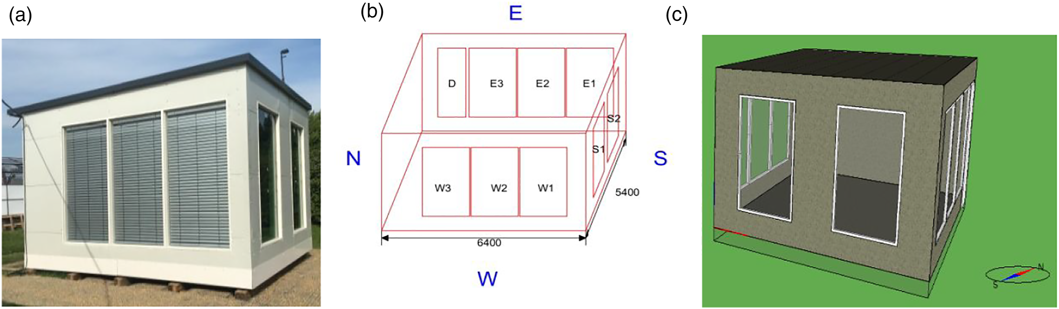
MATELab has overall dimensions of 6.4 x 5.4 x 3.4 m and approximately 35 m2 floor area. It is capable of hosting up to three occupants and it has three glazed façades on the South (S1, S2), East (E1, E2, E3) and West (W1, W2, W3), whereas the north façade is an opaque wall. Its glazed façades can be easily changed or covered with opaque insulated panels in order to test alternative façade technologies or particularly oriented. MATELab’s envelope is highly insulated with external profiled and sealed polyurethane panels in order to provide high thermal efficiency and airtightness, minimising thermal bridges and air infiltration. All the artificial services in MATELab (lighting, heating, cooling and ventilation) have been designed to ensure comfortable conditions and a high level of Indoor Environmental Quality (IEQ) for occupants. Figure 7 shows the real MATELab experimental facility, its 3-D CAD drawing and the model in IDA ICE software. (a) The real MATELab experimental facility, (b) The 3-D CAD drawing and (c) The model in IDA ICE (retrieved from
30
).
The whole model consists of a single zone office occupied by two people on a weekday working schedule from 08:00–17:00. For all other days (weekends and holidays), the office is unoccupied. Each occupant is modelled as an internal load of 120 W (CIBSE Guide A – Environmental Design (2015, revised Jan. 2021)). Furthermore, it is assumed that each occupant uses electronic equipment (laptop, printer etc.) which corresponds to 50 W/person, operating only during office working hours. The lighting system consists of dimmable LED lamps regulating the illuminance level to at least 500 lux in the open office zone with mainly paper based work (CIBSE The SLL Lighting Handbook (2018)). The nominal lighting power is set to 12 W/m2. Lighting control is continuous, meaning that the overhead lights dim continuously and linearly from maximum to minimum light output as the daylight illuminance varies.
The HVAC system is assumed to have an unlimited capacity for heating and cooling (ideal loads air system). According to CIBSE Guide A – Environmental Design (2015), the HVAC heating set-point is set to 20°C for the occupied hours (08:00–17:00) and 14oC during the rest of the unoccupied time while the cooling set-point is set to 24oC and 30oC, respectively. The ventilation is mechanical, set to 14 lt/s/person during occupied hours and 1.4 lt/s/person during the unoccupied time. The infiltration was assumed to be of a constant value of 0.3 air changes/hour throughout the year.
The Venetian blinds incorporated in the CCFs are controlled via a binary control logic allowing the Venetian blinds to be deployed only whenever external incident radiation on the façade exceeds the threshold of 250 W/m2. This mode of operation is active during the whole day and throughout the year. CCF configurations with their specific optical and thermal characteristics were imported into the model from Table 1 and the indoor climate and energy models were created for nine different location-climate types described in Table 2.
Results and Discussion
Indoor climate and energy analysis of the TGU-baseline and the nine CCFs configurations presented in Table 1 were performed in EnergyPlus 9.4.0 and IDA ICE 4.9.9 for nine locations-climate classes described in Table 2. For each combination type of façade-location, the comparative study focused on the following: 1. From the energy efficiency point of view: (i) the total annual energy demand per unit of floor area in kWh/m2 and (ii) the total annual energy consumption (heating, cooling, ventilating and lighting) in kWh 2. From the thermal comfort point of view: (i) the percentage of total occupant hours with thermal dissatisfaction, (ii) the percentage of hours when the operative temperature is above 27°C, (iii) the Fanger’s comfort indices and (iv) the thermal comfort according to EN 15,251 3. From the visual comfort point of view: (i) the Daylight Factor (%) and (ii) the average illuminance (lux), both on a working plane 0.8 m above floor level and 0.5 m from the perimeter.
The simulations revealed that the most overall efficient CCF configuration is the CCFT2 (Figure 6) with integrated white horizontal Venetian blinds (VB1). The quantified percentage improvement (100*(TGU-CCF)/TGU) of each of the above performance metrics of the CCF compared to the traditional TGU, for each location investigated, is displayed in Figure 8. The improvement achieved from an energy efficiency point of view lies in the range 17.6% (Helsinki) – 36.9% (Sydney), increasing from continental to temperate climates. The improvements using a CCF are mostly due to the benefit achieved in terms of g-value when it integrates Venetian blinds in the CCF cavity (Table 1 shows a g-value of 0.065 for CCF with white blinds and 53/23 LE coating). Therefore, the CCF, compared to the TGU, is more efficient in reducing solar gain through the façade, which is the main contributor to energy consumption in cooling-dominated climates where the improvements achieved using CCFs are mainly related to the reduction in the cooling load. For instance, the CCF compared to the TGU in Dubai achieves a decrease in heating load of only 1.5 kWh/m2, whereas the achieved cooling load decrease is 83.6 kWh/m2. Performance improvements (%) of CCF compared to conventional TGU.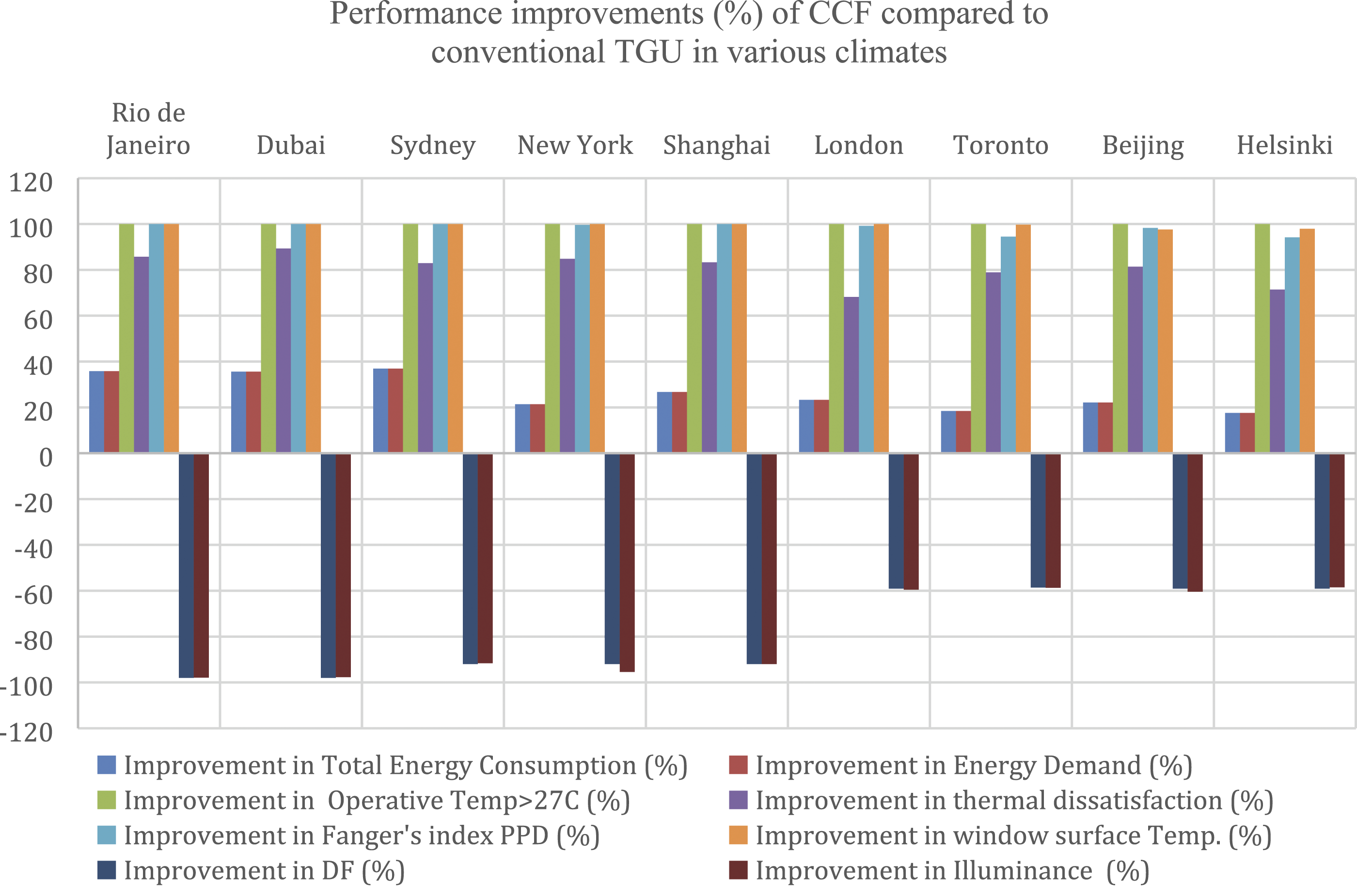
Comparing the effect on the reduction of the energy consumption of the blinds’ colour and the type of glass coating results that the lighter coloured blinds and the coating 53/23 LE show slightly better performance improvement (about 2%) compared to blinds with a darker colour or the 72/57 LE coating.
From the thermal comfort point of view, the comparative study between CCF and traditional TGU confirmed the expected benefits of the CCF as presented in Figure 8. The improvement in total occupant hours with thermal dissatisfaction when using a CCF was in the range of 68% (London) – 89% (Dubai) increasing from continental to temperate climates. Furthermore, the improvement in the percentage of hours when the operative temperature is above 27°C, with using a CCF instead of a TGU is 100%. This means that using a CCF, for all the climates studied, the operative temperature never exceeded the threshold of 27°C, whereas in the case of the TGU, the percentage of hours when the operative temperature was above 27°C lies in the range 28% (London) – 87% (Dubai). The impact of using a CCF was also examined considering the thermal comfort according to EN 15,251. The result was that for the dry desert hot climate of Dubai, the number of occupancy hours with unacceptable comfort with a TGU is 2005 compared to only 27 when using a CCF. Furthermore, in dry desert hot climates, considering Fanger’s comfort indices (predicted percentage of dissatisfied (PPD) and predicted mean vote (PMV)), the benefits of using CCF compared to TGU were reconfirmed. When a CCF was used, PPD never exceeded the value of 9.9%, whereas in the case of a TGU, PPD was reached values of up to 100% (Figure 9). Fanger’s index PPD in dry desert hot climate (a) for TGU and (b) for CCF.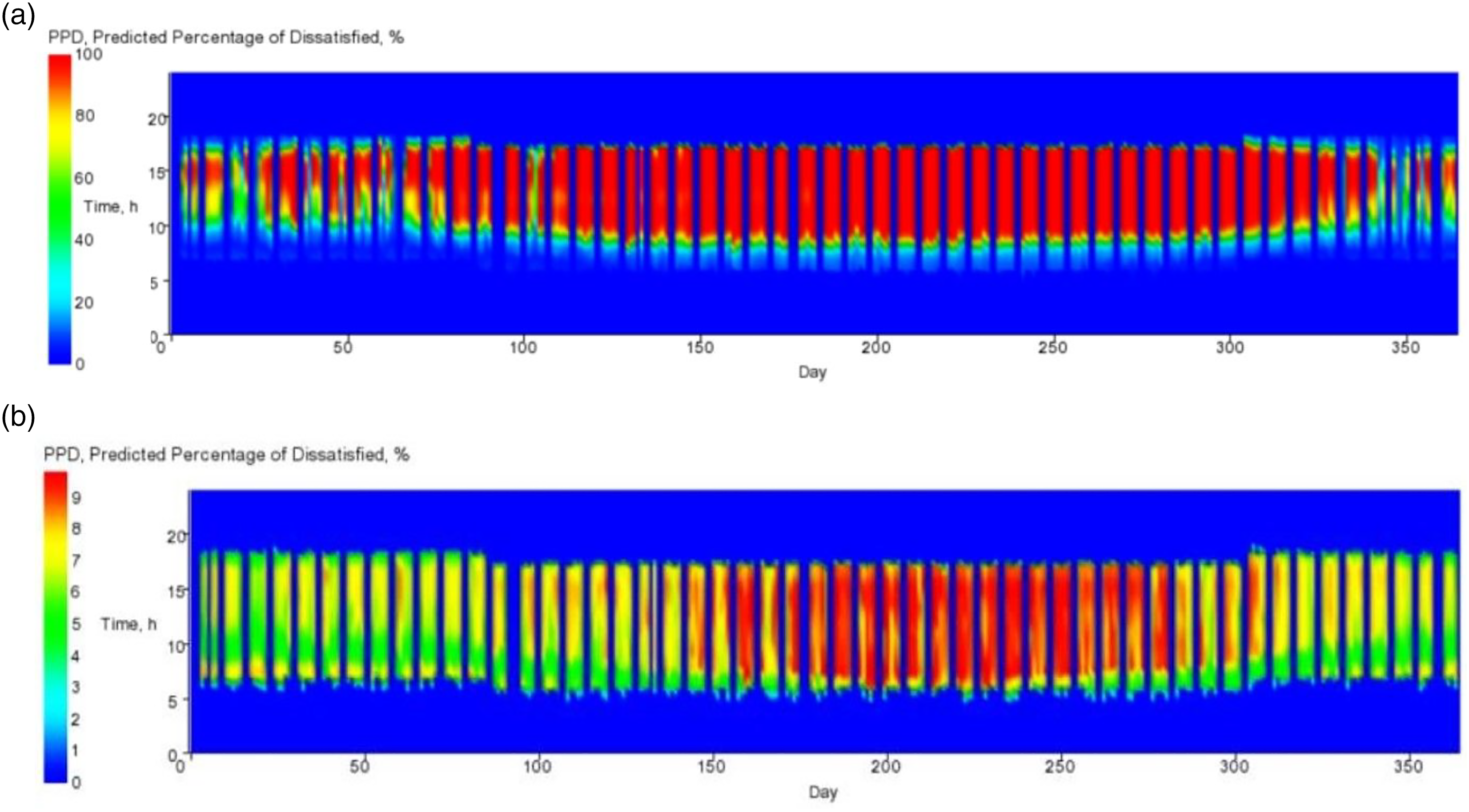
Additionally, considering a PMV comfort threshold between −0.5 and 0.5, Figure 10 shows that the CCF never exceeded this threshold (max value 0.48) while the TGU is possible to reach the value of 5.05. Fanger’s index PMV in dry desert hot climate (a) for TGU and (b) for CCF.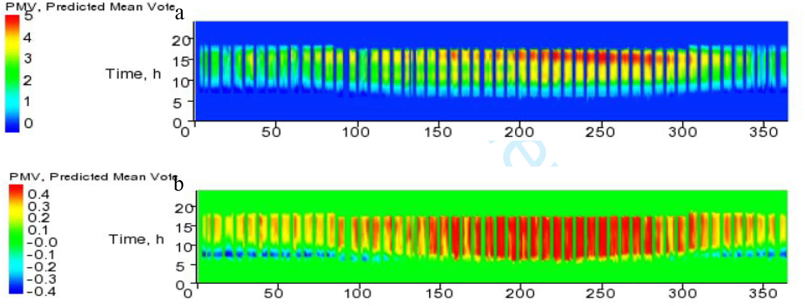
A factor that significantly affects the occupants’ comfort, particularly those sitting adjacent to windows, is the window surfaces’ temperatures developed during the occupancy hours. In this regard, this study particularly examined the surface temperatures of the windows of the model, for a typical summer day in dry desert hot climates, and the results are displayed in Figure 11. It is observed that when a TGU is used the windows’ surfaces reach the value of 46°C compared to the significantly lower value of 31°C in the case of using a CCF. Windows’ surface temperatures during a typical summer day in dry desert hot climate when using TGU and CCF.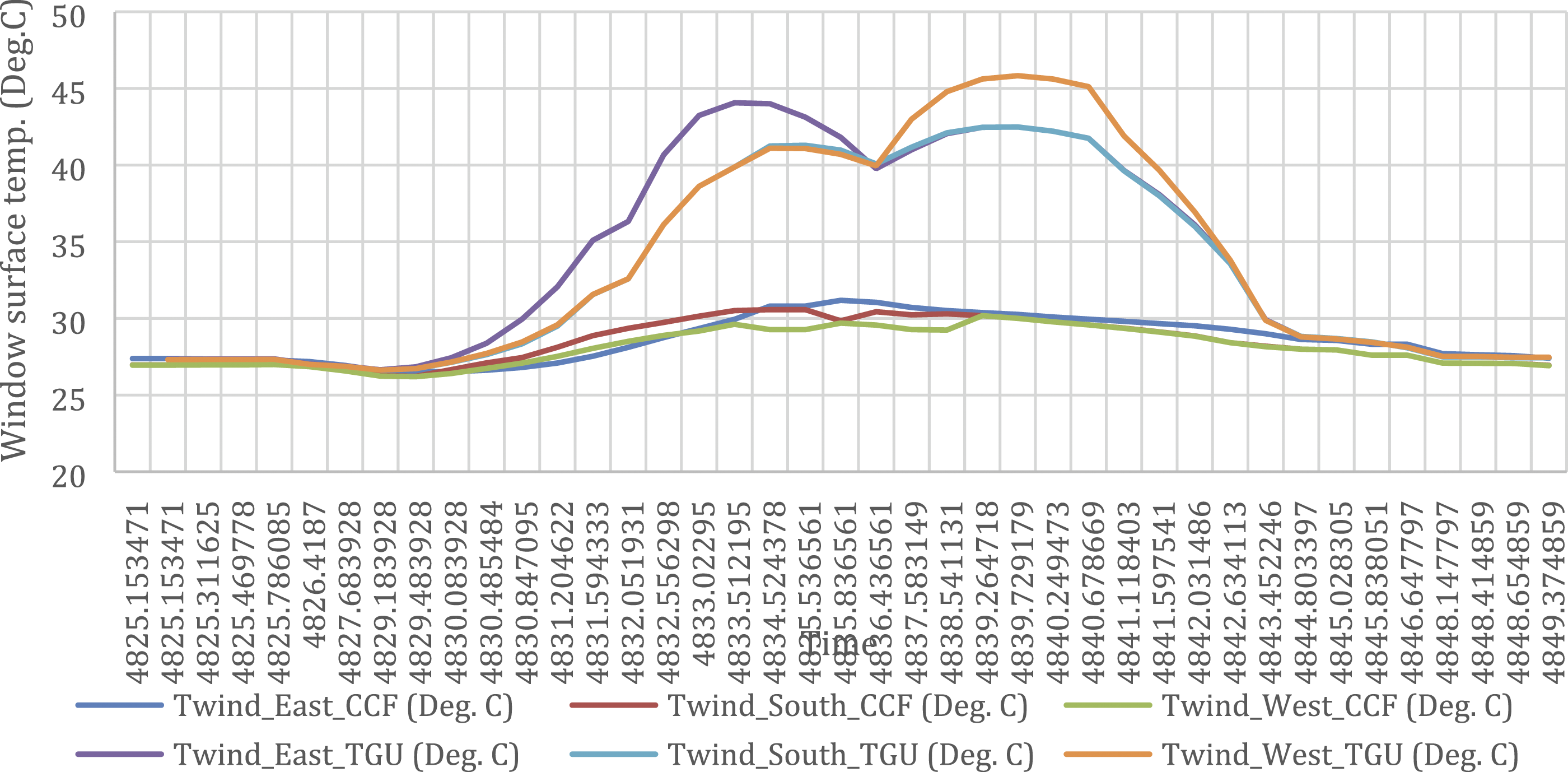
From the visual comfort point of view, two performance metrics were studied, the Daylight Factor (DF) (under CIE overcast sky conditions) and the illuminance (ILL), both measured on a working plane at 0.5 m from the perimeter and 0.8 m above floor level. The comparative results of using CCF or TGU are illustrated, for all the investigated climates, in Figure 8. The DF, when the CCF is used, is significantly reduced by a value in the range of 58–98% depending on the climate. The illuminance was also reduced by a significant amount lying in the range of 58–98% in the case of CCF use. However, the impact of the greatly reduced illuminance levels on increased lighting energy use (especially in overcast cities) has been considered and added to the total annual energy load in the simulations performed. Despite this disadvantage of the CCF, it was observed that, in locations with dry desert hot or continental hot summer climates, the illuminance level achieved using the CCF lies above or marginally near the required threshold of 500 lux for office spaces.
The results of this study, for the climates/locations presented in Table 2 are compared to the results of a previous study
29
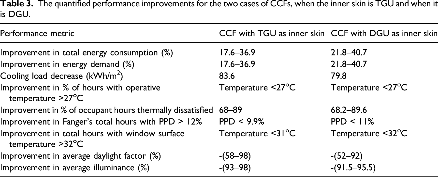
performed by the authors in which the CCF configurations used had, as inner skin, a DGU instead of a TGU used in the current study. In this regard, the quantified percentage improvement (100*(DGU-CCF)/DGU) of each of the performance metrics of the CCF compared to the traditional DGU, for each location investigated, is displayed in Figure 12. For comparison reasons, the quantified percentage improvements for the two cases, when the inner skin of CCFs is TGU and when it is DGU, are shown in Table 3. This comparison revealed that the performance improvements achieved by both cases of CCF configurations are similar noting the larger cooling load decrease when using CCF with TGU as inner skin as well as the slightly lower decrease in visual comfort achieved by the CCF with DGU. Performance improvements (%) of CCF with DGU as inner skin compared to conventional DGU (retrieved from
29
). The quantified performance improvements for the two cases of CCFs, when the inner skin is TGU and when it is DGU.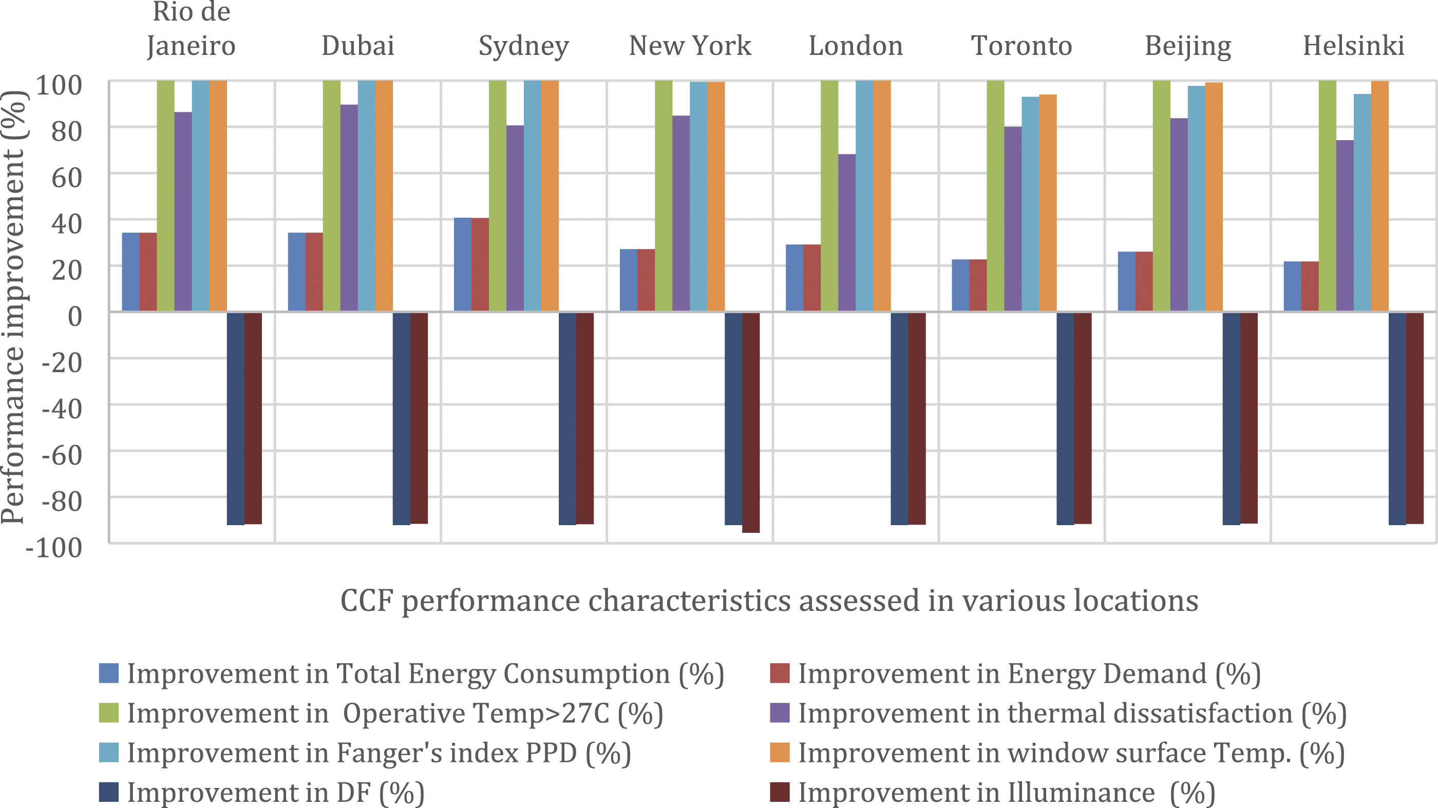
It is worth noting that, for a holistic comparison between a CCF and the baseline (reference glazing), a Life Cycle Analysis (LCA) is needed to identify the difference in construction/installation/maintenance cost, as well as the difference in embodied carbon/embodied energy taken to make the extra façade components of the CCF. In this regard, a hot-spot analysis for the embodied carbon of the extra outer skin of the CCF, based on the Life Cycle Assessment of Buildings: A Practice Guide 35 , resulted to an increase in embodied carbon of 16 Kg CO2 e/m2 of CCF compared to the conventional glazing (TGU with integrated venetian blinds), for London.
Conclusions
This study examines the impact of a novel façade named Closed Cavity Façade (CCF) on the energy performance and thermal and visual comfort of an office-like experimental facility. A traditional triple glazing unit (TGU) and nine different configurations of CCF were simulated in IDA ICE and EnergyPlus building simulation tools, in nine different locations-climates. The performance analysis carried out for the 90 combinations of CCF configuration-climate results in extensive benefits, in terms of energy performance and comfort, of using a CCF compared to the conventional TGU. All the CCF configurations, and in all the climates investigated, led to an improvement of energy performance in the range of 18–37%, depending on the CCF configuration and the climate, compared to the traditional TGU used as the baseline. This is mainly attributed to the improved thermal transmittance and g-value as a consequence of integrating Venetian blinds in the cavity and of applying suitable glass coatings. A higher improvement of energy performance is observed in cooling-dominated locations compared to continental climates since CCF reduces solar gain through the façade, which is the main contributor to cooling energy consumption. Furthermore, this study shows that the use of light-coloured blinds instead of blinds with a darker colour or the use of a 53/23 (Tvis/Tsol) coating on the glass surface six instead of 72/57 LE coating leads to a slight increase in the performance improvement of about 2%. Furthermore, it is worth noting that the proper selection of system components can be an added advantage in reducing the interior surfaces’ temperatures providing extra benefits in terms of occupants’ comfort.
The improvement of the users’ comfort by using a CCF is reconfirmed through the values of Fanger’s comfort indices, PPD and PMV being less than 10% and in the range −0.5–0.5, respectively. Despite its plethora of advantages, the CCF reduces visual comfort by significantly decreasing the DF and illuminance level in the space. This occurs due to the reduced value of its Tvis normally being around 0.1. However, for many climates, such as dry desert hot or continental hot summer, the proper selection of CCF components is possible to result in acceptable average illuminance levels (500lux).
Comparing the results of the current study to the results of a previous study in which the CCF configurations used had, as inner skin, a DGU instead of a TGU used in the current study, revealed that the performance improvements achieved by both cases of CCF configurations are similar noting the larger cooling load decrease when using CCF with TGU as inner skin as well as the slightly lower decrease in visual comfort achieved by the CCF with DGU.
This study, in addition to the conclusions it reached, brought to light new research questions for future work, such as validation of simulated CCF, investigation of overheating in the CCF cavity, transient performance analysis of CCF using CFD and performance analysis of CCF using different blinds control strategies and slat angles.
Footnotes
Acknowledgements
The present work has been developed in the framework of a PhD research project. The authors gratefully acknowledge the EPSRC for funding this research through the EPSRC Centre for Doctoral Training in Future Infrastructure and Built Environment (EPSRC grant reference number EP/L016095/1).
Declaration of conflicting interests
The author(s) declared no potential conflicts of interest with respect to the research, authorship, and/or publication of this article.
Funding
The author(s) received no financial support for the research, authorship, and/or publication of this article.