
Abstract
This study proposes an adaptive neurofuzzy inference system (ANFIS) for field oriented control (FOC) of a permanent magnet synchronous motor (PMSM) for multicopter applications. FOC is the most widely used speed control method for PMSMs. The utilization of linear control algorithms may not be sufficient for this type of systems due to the nonlinear characteristic of the PMSM and the presence of uncertainties such as parameter variations and external disturbances. In particular, in high power and agility applications, conventional PI controllers alone may cause undesired speed overshoot which degrade the performance of the multicopter. This paper proposes more comprehensive speed control of a PMSM drive employing an ANFIS, which offers improved tracking performance in terms of settling time and overshoot under various operating conditions. The proposed ANFIS controller implements the adaptive approach using offline training data over a PI controller that is tuned to the nominal operation of the PMSM, specifically targeting the speed error and the rate of change of error in speed. The training data is obtained from a dynamic model of the PMSM operating with a conventional PI controller. The performance analysis of both controllers under different operating conditions is simulated, and experimentally verified. By using the ANFIS controller, the overshoot is reduced from 6.17% to 1.57% at no load condition, from 36.3% to 6.23% at load, and the settling time is almost halved in both cases compared to a conventional PI controller.
Introduction
In recent years, AC drives in aerial and electric vehicles have attracted attention due to the threat of global warming, increasing population, energy demand, and cost (Yılmaz, 2015). Considering the advantages such as adjustable, improved speed, and torque control, PMSMs have also become a top research topic in robotics, electricity, gas, and oil industries (Marufuzzaman et al., 2010; Shang et al., 2015; Vindel et al., 2012). As the market for urban air mobility expands day by day, environmental issues such as CO2 emissions have emerged. Aircraft applications require high reliability, high-power density, and increased efficiency with weight savings and reduced torque and CO2 emissions (Cao et al., 2012). The PMSMs meet the requirements of aircraft applications and electric vehicles by offering reduced fuel consumption, high-power density, and clean energy. Conventional propulsion systems are gradually losing popularity as the technology develops. In terms of technology assessment, hybrid electric vertical take-off and landing (VTOL) aircraft have come in to the fore in aviation (Cakin et al., 2020). In addition, almost all multicopter vehicles (quadcopters, octocopters, etc.) also known as drones, move using either brushless direct current (BLDC) motors or PMSMs. Although the speed control of BLDC is simpler, PMSMs offer higher torque and efficiency. As a result, PMSMs are the preferred solution for generating thrust in drones. On the other hand, accurate speed control of motors is crucial for the stability and performance of the drones (Chan and Woo, 2015). Therefore, a better control method is required to utilize PMSMs for drones that provide low overshoot and settling time.
PMSMs consisting of distributed windings on the stator and permanent magnets on the rotor, when supplied with sinusoidal stator currents and have a sinusoidal back EMF producing a constant torque (Pillay and Krishnan, 1988). Various control methods are proposed in the literature for the PMSM drive, which may be divided into scalar and vector control. Scalar control is used in variable speed applications where the angular speed is unknown in the open loop. In this method, the magnitude of the voltage changes at a constant rate with frequency. The advantage of this method is that it allows the motor to operate in a sensorless mode, as this algorithm does not require the angular speed or the actual rotor position. However, this control technique is only applied when the motor is in steady state. Vector control techniques allow both motor flux and torque to be controlled by stator currents. This technique ensures high accuracy, an extended speed range, reduced settling time, and reduced losses. The main vector control techniques for PMSMs are field oriented control (FOC) and direct torque control (DTC). The DTC allows for direct control of stator flux and electromagnetic torque. While the DTC method avoids computational burden and can be implemented without a speed sensor, it results in higher torque and current ripple compared to the FOC method.
The most common control method for PMSM is FOC. This method achieves torque and flux control of the motor by using appropriate field orientations, which depend on the phase currents in the stator, and employing Park and Clarke transformations. A FOC-based PMSM drive includes direct and quadrature (d–q) axis current control in the inner loop and speed control in the outer loop (Salem et al., 2018). Since the speed controller operates in the outer loop, its loop frequency is lower than that of the current controller. The study contributes to the field of PMSM control by proposing a robust predictive speed control algorithm enhanced by a novel extended state observer (ESO). This approach addresses the challenges posed by nonlinearity, parameter variations, and external disturbances. It also improves performance in terms of settling time and overshoot (Zhao et al., 2019). Speed control using the FOC method is usually integrated with a PI controller due to its simple design. However, fine-tuning the PI parameters is a challenging task, when designing a PI controller for the PMSM. The linearization technique is employed to approximate the behavior of the system around a specific operating point, which may not maintain optimal performance over the entire operating range. The parameter variations and disturbances introduce unwanted uncertainties into the nonlinear model of the PMSM, and increase the complexity. Especially in high power applications, most of the linear control methods suffered from the above mentioned problems (Yadav and Verma, 2018). In recent literature, various advanced nonlinear control methods have been proposed and implemented to improve the dynamic response of the PMSM speed control system, enhance its robustness, and minimize power losses in the drivetrain. These methods include linearization control (Aghili, 2018), adaptive control (Chen et al., 2019; Hu et al., 2016), sliding mode control (Liu et al., 2018; Qian et al., 2018), fuzzy control (Shanthi et al., 2021), and neural network control (Wang and Tsai, 2017; Yu et al., 2018). Artificial intelligence (AI) controllers have become increasingly popular and are used in wide range of applications (Mopidevi et al., 2024). Fuzzy controllers, adaptive neurofuzzy inference systems (ANFIS) are proven to be particularly effective in the developing automotive and aerospace fields. Fuzzy control, based on fuzzy logic, is ideal for controlling systems that are noise-sensitive, nonlinear, or not well-defined. Instead of relying on a precise mathematical model, it uses ranges of values interpreted by linguistic variables. This approach is suitable for systems where exact relationships are difficult to establish, reducing the need for constant expert supervision. A fuzzy inference system is required to generate the desired input–output pairs by constructing if–then rules with appropriate membership functions (MFs) (Shanmugasundaram et al., 2022). However, the design of a fuzzy control system is complex, because it requires the careful selection of MFs and the development of control rules that dictate the behavior of the system, which requires a deep understanding of the system. In contrast, artificial neural networks (ANNs) provide an alternative approach to system control. They have the ability to learn and automate processes by recognizing relationships between inputs and outputs. They can be trained with a variety of learning algorithms, allowing them to adapt to changing environmental and dynamic conditions. Unlike fuzzy controllers, ANNs do not require explicit rule setting; instead, they learn from patterns and trends in the dataset provided. This allows them to learn the behavior of the system over time and develop more adaptive control strategies. In Xie et al. (2018), plug-in hybrid electric vehicles (PHEVs) using an electric management system (EMS) built on ANNs show a significant 17.7% reduction in energy consumption when the initial state of charge (SoC) was at 0.85. The study by Intidam et al. (2020), also show that PI-ANFIS collaboration in BLDC motor drive applications has a quite fast computational speed for predicting and tuning the parameters of the conventional PI controllers integrating both offline and online gain adjustments. In Singh et al. (2022), the authors compared three major controllers, which is also the benchmark of our study: PI, fuzzy logic, and ANFIS controllers. Among the three designed controllers, the results indicate that the ANFIS controller had the shortest settling time and minimized the overshoot by reducing the oscillations. The authors Guo and Mohamed (2020) stated that some ANFIS configurations, including ANFIS online-based GA-PSO (genetic algorithm and particle swarm optimization) optimized BLDC motor speed control and ANFIS-based rotor position control, in the different direct current (DC) motor drive techniques have better performance in overshoot, rise time, and settling time compared to conventional methods such as PI control.
As FOC offers the significant benefits mentioned above, such as smooth operation and advanced control, this study focuses on speed control via FOC, using two methods: a conventional PI controller and an ANFIS controller for the aerospace domain. Since PI controllers are suboptimal for nonlinear systems with highly variable operating conditions, an ANFIS-based PI controller is proposed as a solution to the disadvantages of a conventional PI controller for PMSM drives. The ANFIS controller is designed using training data collected from a PMSM dynamic model with a PI controller, which is then imported into the ANFIS in the MATLAB Simulink. This controller can learn and adapt to nonlinear dynamic systems (Kusagur et al., 2010) using the fuzzy inference and neural network mechanisms.
The contributions of this article are as follows: Modern techniques for electrical drivetrains have recently become feasible in terms of safety standards although the modern techniques based on ANFIS have been studied on flight control topics related to flight dynamics such as altitude and attitude performance (Al-Fetyani et al., 2021). This study focuses specifically on electrical drivetrain applications of multicopters in aviation. The proposed ANFIS method in speed control utilizes an adaptive flow for a nonlinear system, which, strongly compensates parameter variations and external disturbances unlike the conventional PI control approaches. The advanced control technique of ANFIS is designed to improve the tracking performance by targeting the shortened settling time, minimizing the overshoot by adjusting the control inputs accordingly. The proposed method resulted in a 70% reduction in overshoot and almost halved the settling time compared to a classical PI controller. The proposed approach also presents a very low steady state error, which is negligible, although the method is highly sensitive to the accuracy of the training data. The article is structured as follows: first, the dynamic model is derived from the mathematical expression of the PMSM using the d–q axis quantities in the rotating rotor reference frame, and the FOC is performed. The article then focuses on design of two types of FOC-based speed controllers: a conventional PI controller and an ANFIS controller. The combination of a PI controller and FOC allows accurate speed tracking. To achieve this, design criteria are used to adjust the PI parameters. In addition, an ANFIS controller is proposed and designed using offline training in the MATLAB Simulink environment to serve as a speed controller. Experimental results are obtained using a noncomplex communication interface. The performance of both controllers is presented, compared, and analyzed in terms of overshoot, steady state error, and settling time in both simulation and real-time tests. The flow chart of the study is given in Figure 1(a).
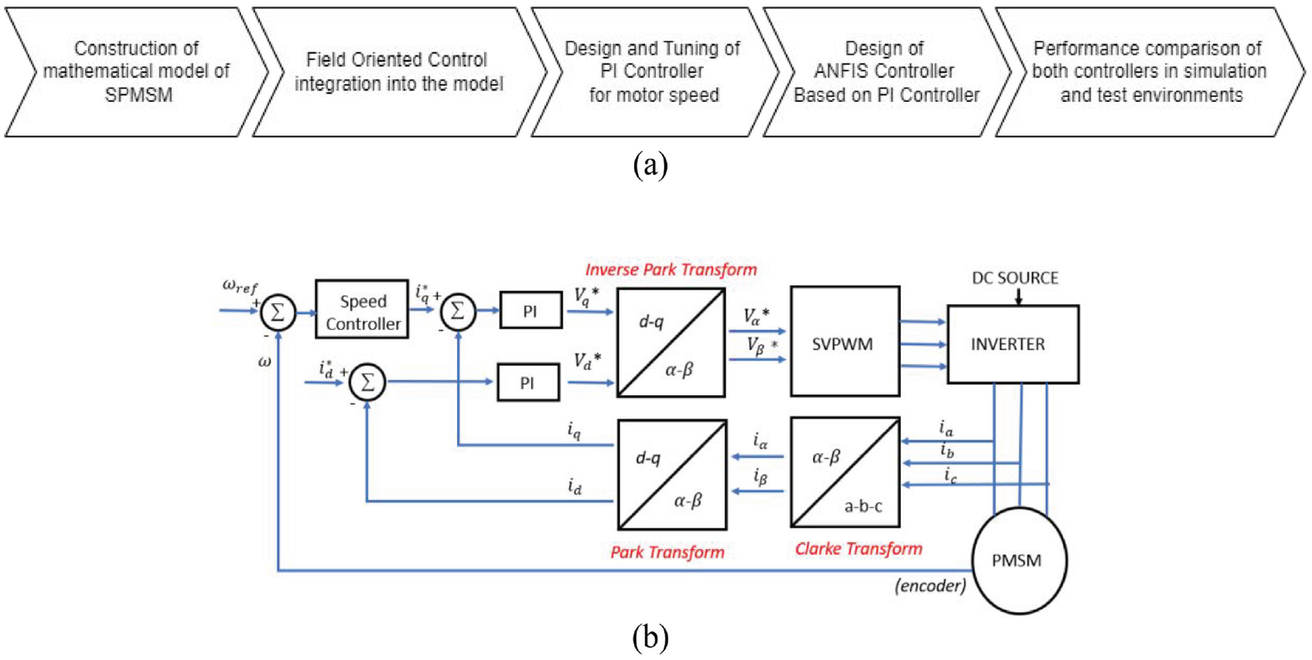
(a) Workflow of the whole system and (b) PMSM FOC-based motor drive scheme. FOC: Field Oriented Control; PMSM: permanent magnet synchronous motor.
Mathematical model of PMSM motor and drive
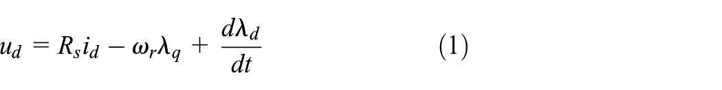
A surface-mounted PMSM (SPMSM) has a fixed reluctance for any rotor angle due to the uniform air gap, and the direct axis inductance is equal to the quadrature axis inductance (Wang et al., 2009). The voltage expressions in the d–q axis rotor frame for the PMSM are given in equations (1) and (2) (Pillay and Krishnan, 1989). As the system is symmetrical, the zero axis components are ignored (Chi, 2007).

The flux linkage expressions for the d–q axis depicted by


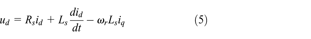
Equations (5) and (6) give the voltage expressions for the SPMSM in the d–q axis (Pillay and Krishnan, 1989).


Substituting equations (3) and (4) into equation (7) gives equation (8).


The FOC-based motor drive scheme for the PMSM and d–q coordinate system transformation is shown in Figure 1(b).
The FOC requires the stator currents and the rotor angle values to control the motor torque and the flux. The stationary reference frame contains three phase quantities which are at fixed angles, although their amplitude changes with time. The control of the model becomes complex, as the fluxes, currents, induced voltages, and flux linkages vary with time. The Park and Clarke’s transformations eliminate the controller design challenges of time-varying amplitude by providing a reference frame. Equation (11) gives an equivalent resistance of the inverter board (Ogata, 2010).

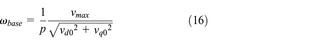
The maximum phase voltage of the inverter output is expressed as:

In the constant torque range of the motor,


An inverter calculates the three-phase AC output voltage from the inverter DC voltage using the modulation indices between 0 and 1. A commercial inverter operates as a full wave inverter. Da, Db, and Dc are the modulation indices. Vdc is the DC bus voltage of the inverter. The stator output voltages in volts are represented by Va, Vb, and Vc. DC to AC conversion is performed using equations 18, 19, 20, and 21 (Ogata, 2010).


PI-based FOC speed controller design
The PI controller combines a proportional and integral gain to achieve both fast response and reference tracking. The proportional gain ensures fast output, while the integral gain reduces output error. In the constant torque region, the d-axis current reference is set to 0. The q-axis current control is cascaded with speed control. Initially, the d–q axis current control is used. The PID Tuner automatically tunes the parameters of the PI controller for a Single Input Single Output (SISO) system to achieve a balance between robustness and performance. This transfer function based method determines the discrete time settings. The drive system sampling time settings are chosen to be 25
ANFIS-based FOC speed controller design
The ANFIS is a hybrid intelligent system that combines the ANN and fuzzy logic (FL) technologies (Salem et al., 2018; Shanthi et al., 2021). Fuzzy systems can be used for modeling, data analysis, prediction, control, etc.
A fuzzy inference system uses fuzzy logic to map a given set of inputs to a set of outputs. The process can be divided into five parts: input scaling, fuzzification, rule-based inference, defuzzification, and output scaling. Fuzzy rules represent a relationship between variables, with the antecedent proposition defined by “IF” and the consequent proposition defined by “THEN.” The foundations of a fuzzy rule base include linguistic variables, linguistic terms, semantic rules, MFs, and base variables. A MF is used to determine the degree to which an input variable fits into a particular set. The scheme for the fuzzy inference system and a simplified ANFIS adaptation scheme with two inputs are shown in Figure 2(a) and (b), respectively (Han et al., 2023). This ANFIS structure uses adaptive nodes to change the parameters of the MFs and Sugeno outputs (f1 and f2)) using a backpropagation (BP) algorithm (Nour and Too, 2006).
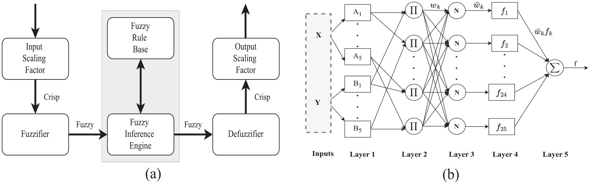
The fuzzy inference system (a) operating mechanism and (b) five layers example of ANFIS scheme with 2-input-1-output (Han et al., 2023). ANFIS: adaptive neurofuzzy inference system.
ANFIS is associated with Takagi-Sugeno (T-S) fuzzy models. T-S fuzzy model requires crisp functions, and its rules are defined as (Han et al., 2023).
In general, fi is defined as a vector-valued function. The rules are expressed in the following form in order to obtain a practical parameterization (Han et al., 2023):

Firing strength is computed as

T-S fuzzy model output can be found using the firing strength expression as given in equation (25) (Han et al., 2023).

The neural network model can learn from training data to model, specify, or estimate nonlinear functions. The ANFIS algorithm is a hybrid learning algorithm consisting of a forward pass and a backward pass. ANFIS can create an input–output mapping by combining human knowledge with a fuzzy rule base and input–output data.
The adaptation process ends when the FIS output converges to the specified limit. The ANFIS consists of first or zeroth order T-S type systems, combined with a single output. All MF outputs are defined as either linear or constant. Each MF has a unique rule with a unity weighting. The node function at layer 1 is obtained as follows (Han et al., 2023):


where x and y are inputs,

The outputs of layer 3 satisfy the normalized firing strength. Equation (29) provides the computation of the normalized firing strength (Han et al., 2023).

Each node functions adaptively at layer 4, with modified consequent parameters (

Layer 5 is a single node that receives the sum of all neural signals. The weighted average defuzzification is given by equation (31) (Han et al., 2023).

During the offline training process, the ANFIS toolbox imports the input–output training data from the PMSM reference drive model with a PI controller. The design of the ANFIS controller uses two input datasets and one output dataset from the reference model. The inputs to the ANFIS controller are the error (e) between the actual motor speed and the reference speed, and the error change (Δe), which are collected during the training data processing. The output is assigned the control signal variation (du). Equations (32) and (33) express the error and the error change. Where ωref is the reference speed and ωm the actual motor speed (Kuvvetli et al., 2021).


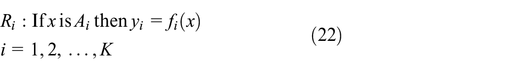
The proposed ANFIS mechanism for the PMSM and the controller design flowchart are shown in Figure 3(a) and (c), respectively. In Figure 3(a), the error and the error change modify the control signal through the construction of a fuzzy logic-based neural network. The process of setting up and optimizing an ANFIS controller for a PMSM using MATLAB includes initializing the ANFIS editor, importing training data, determining and selecting MFs, and performing optimization iterations based on performance metrics such as a mean absolute error (MAE) or error tolerance. After following the steps in the given controller design flowchart, the ANFIS file is converted to the fis extension and this file can be directly imported into MATLAB Simulink, which illustrates the proposed ANFIS speed controller in the Figure 3. The speed range is divided into 20 subsections, each with 10 positive and 10 negative values. This subdivision significantly reduces the error between the actual data from the reference model with a PI controller and the ANFIS-trained data.
Proposed ANFIS mechanism (a) schematical view, (b) modeled ANFIS structure for speed control, and (c) flowchart. ANFIS: adaptive neurofuzzy inference system.
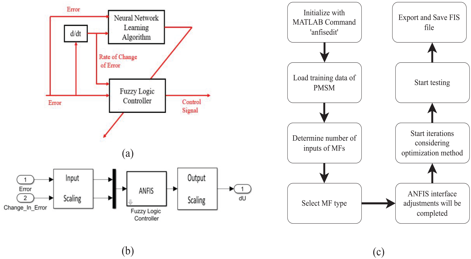
In the ANFIS interface, the most suitable MF types are selected by considering the high-precision speed tracking performance in relation to the training error of the iterations. Determination of the optimal type and number of MFs is essential for minimizing training errors in motor drive applications. A small number of MFs may inadequately represent the complexity of the system, resulting in high errors, while an excessive number of MFs may lead to overfitting and instability in the test environment. Triangular MFs are particularly effective as they can accurately capture both sharp and smooth transients. The best performance response is achieved with five triangular Sugeno type MFs for both inputs. The proposed technique combines the least squares estimation (LSE) and back propagation (BP) algorithms to adjust the parameters at the adaptive nodes. The MFs of the error are identical to the MFs of the error change. Up to six MFs are selected to avoid computational burden. The FIS data is overlapped with the reference data to train with a MAE of 2%. There are 25 ANFIS rules in total, covering all possible combinations of the fuzzy sets (MFs) for the two inputs, as each input requires 5 MFs. Regarding the rule table in Table 1, each rule invokes specific premises based on the input memberships, orienting to a specified output action. Each rule is given equal weight, indicating equal importance. One of the 25 rules states that if the error falls within the range defined by the fuzzy set in1mf1 and the change in the error is within the range defined by the fuzzy set in2mf1, the corresponding output action is described by the fuzzy set out1mf1.The input scaling factors of the error and the change in the error are 0.55 and 1.7, respectively. As the output of the ANFIS block is the change in the control signal, this change in control signal is integrated over time and scaled by 1 and saturated with respect to the maximum inverter current. ANFIS parameters for Input 1, Input 2, and Output are provided in Tables 3, 4, and 5, respectively. The motor used in the study is a Teknic 2310P motor. The motor has 4 poles and its stator resistance is 0.36
ANFIS rule table.
ANFIS: adaptive neurofuzzy inference system.
Results and discussion
Simulation results
In this section, the simulated motor performance results of both the PI and ANFIS controllers for no load, speed reversal at no load and under load conditions are presented. The performance of the controllers is compared in terms of their overshoot (OS), settling time, and steady state error. The performance results of the speed tracking simulation at 3000 rpm at no load condition are shown in Figure 4. In Figure 4(a), concerning the motor starting, the q-axis current of the ANFIS controller is slightly higher during a short transient period by satisfying the time domain constraints. Figure 4(b) shows that the ANFIS control provides a critically damped response in terms of the q-axis voltage, and the advanced motor drive technique requires smooth transients. Figure 4(c) shows that the ANFIS controller has better results in terms of the settling time and speed overshoot compared to the conventional PI controller. The ANFIS controller improves the transient response by reducing the overshoot from 4.57% to 1.6% and the settling time from 0.211 to 0.1344 s compared to the PI controller. The ANFIS algorithm extends the speed performance and mitigates the inaccuracies, unknown dynamics, or dissipation. According to Figure 4(d), the PI controller oscillated more around the reference motor torque compared to the ANFIS controller (Kuvvetli et al., 2021). Regarding Figure 4(e), the stator currents of the ANFIS controller are significantly lower at starting conditions over a long transient period. Thus, the ANFIS controller helps to reduce fine tuning sensitivity of the PI controller. However, the estimation procedure using the training data in the ANFIS method introduces unwanted ripples around the torque reference signal. The steady state error of the ANFIS controller for this scenario is 0.17% and is negligible.
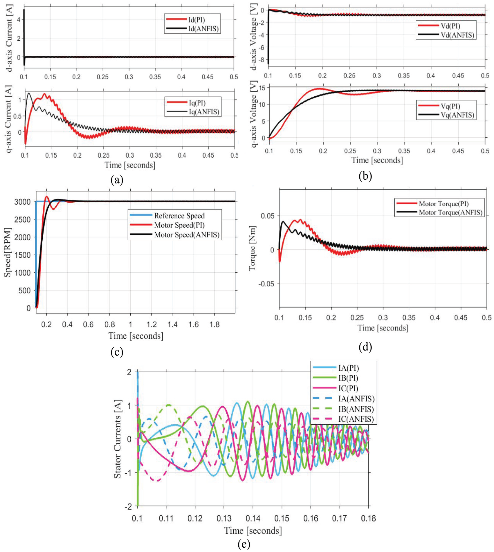
No load results at 3000 rpm (a) d–q axis currents, (b) d–q axis voltages, (c) speed, (d) motor torque, and (e) stator starting currents.
The no load speed reversal characteristics are derived at 3000 rpm. Figure 5 shows the corresponding speed reversal responses for both controllers. Figure 5(a) and (b) show the d–q axis currents and voltages, respectively. The PI controller embodies undesired oscillations in the d–q axis currents and voltage responses. The ANFIS controller suppresses the oscillations and reduces the uncertainties when the reference speed is reversed while the PI controller still suffers from the fluctuations as shown in Figure 5(c). The robustness performance of the ANFIS controller is superior to the conventional methods. The ANFIS controller significantly reduces the speed transient response by reducing the OS from 6% to 2.72% and the settling time from 0.24 to 0.23 s. The torque response of the speed reversal is shown in Figure 5(d). The ANFIS control retains its robustness to torque dynamics even though the drive system is subject to torque ripple. However, the ANFIS controller achieves a robust performance response, which is a strict constraint for the performance optimization. Figure 5(e) shows the transient behavior of the stator currents for both controllers. One of the drawbacks of the PI controller-based drive system is that the system is subjected to high-current draw for a long transient period. The steady state error of the ANFIS controller (0.172%) can be ignored as it does not exceed the specified error limits (0.5%).
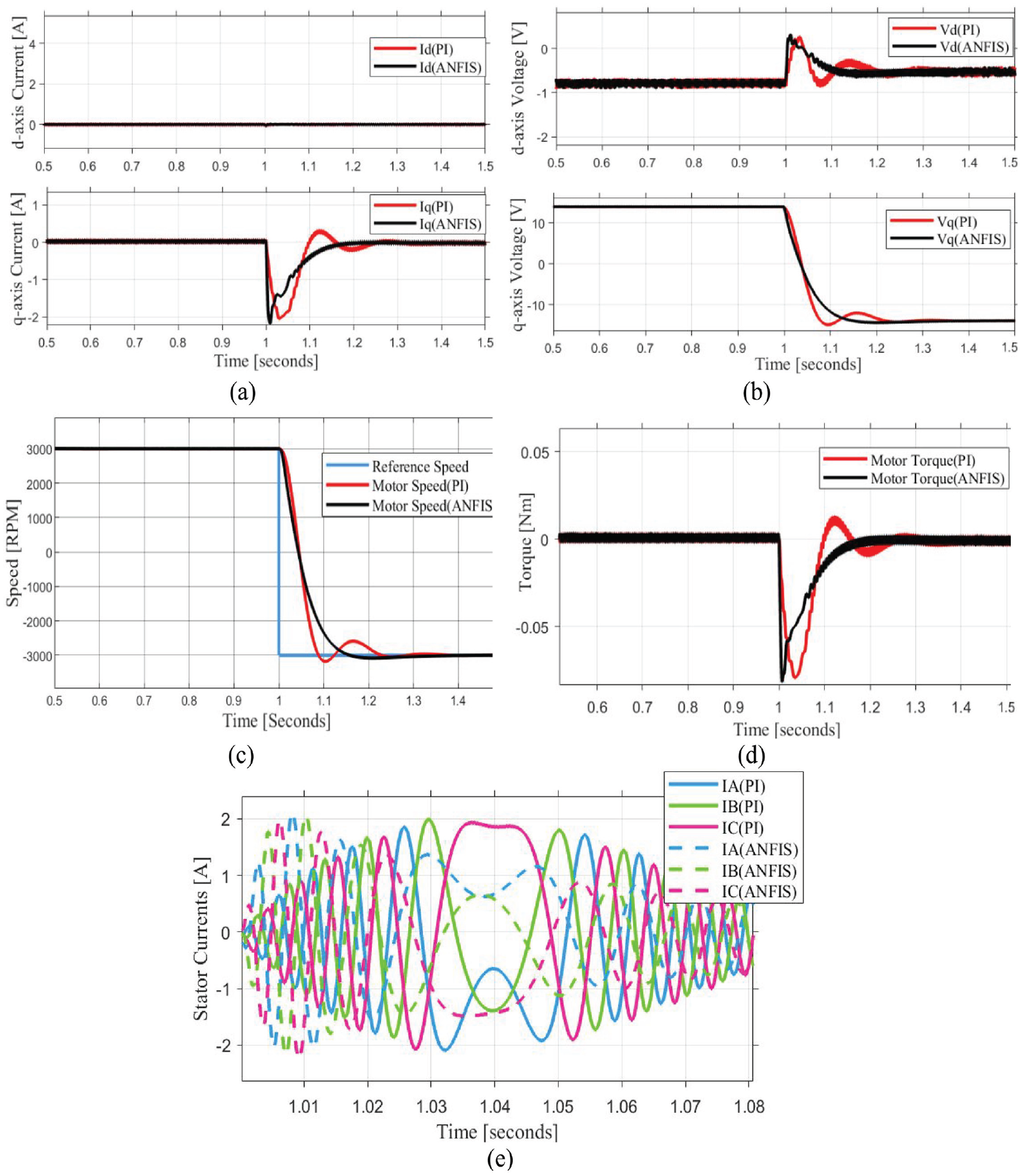
The speed-reversal results at no load (a) d–q axis currents, (b) d–q axis voltages, (c) speed, (d) motor torque, and (e) stator starting currents.
The simulation results of the motor operating at 3000 rpm with a load of 0.10 Nm are shown in Figure 6. A significant difference in the overshoot can be seen in Figure 6(c). The PI controller exaggerates the magnitude of the motor speed in the transient region. The overshoot values of the ANFIS and the PI controller are obtained as 1.33% and 10.53%, respectively. This result means that the system with the PI controller is highly affected by the load torque or the load changes at any time. In addition, the system response of the ANFIS controller (0.14 s) is faster than that of the PI controller (0.215 s) until the system outputs settle within the specified control design error bounds.
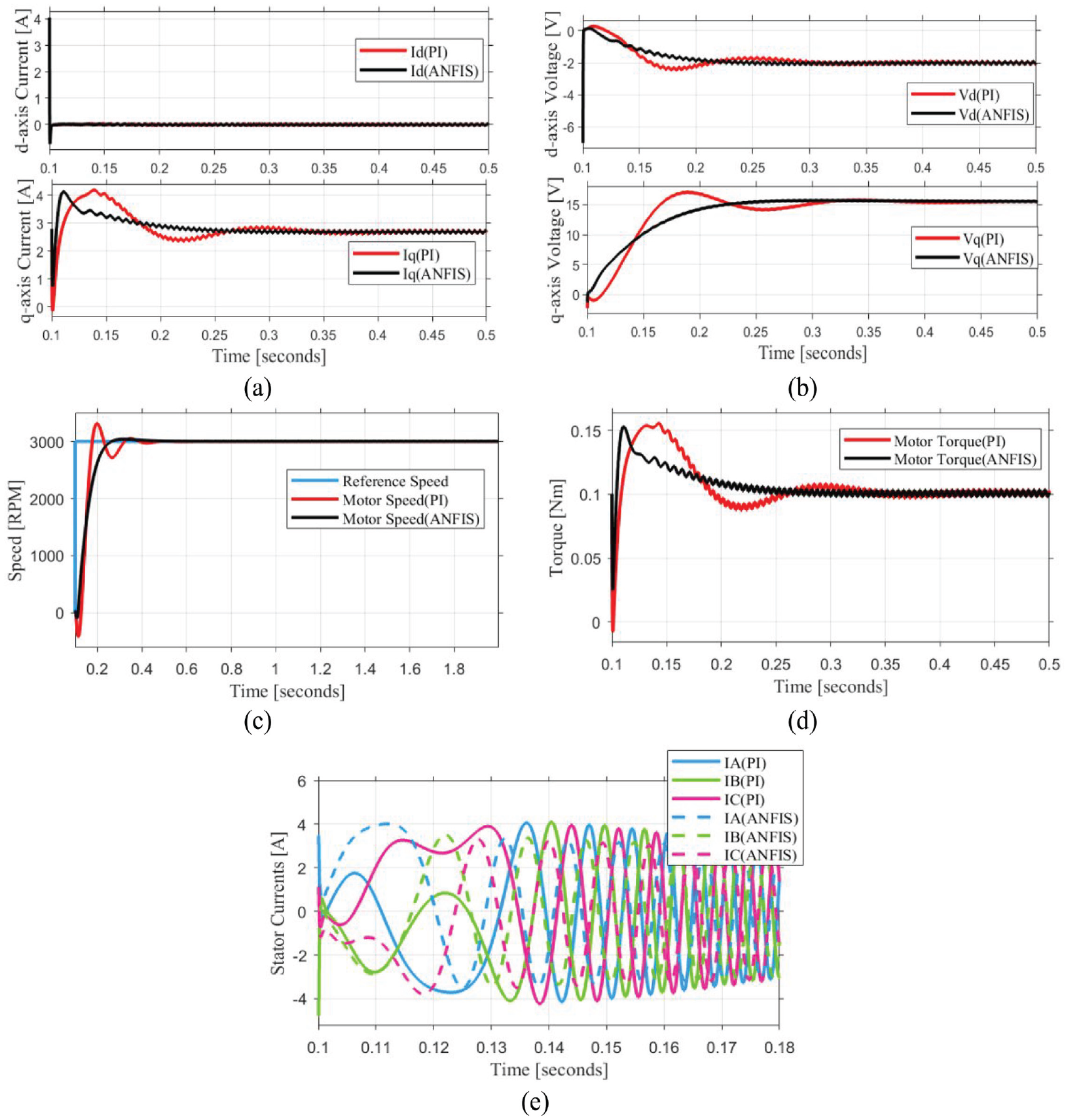
The results under 0.10 Nm load at 3000 rpm (a) d–q axis currents, (b) d–q axis voltages, (c) speed, (d) motor torque, and (e) stator starting currents.
The ANFIS control abruptly suppresses the reverse machine torque and has a fast response to reach the steady state as shown in Figure 6(d). Figure 6(a) and (b) show the current and voltage characteristics of the d–q axis. The ANFIS controller forces the d–q axis quantities to the generated reference value within the short settling time without any oscillations. The selected controller type determines how the starting stator currents are amplified and the relative results are compared in Figure 6(e). As a result, the ANFIS controller dominates the overshoot and machine dynamics.
Experimental results
The proposed method is also tested and the test bed is shown in Figure 7. An experimental setup to implement the FOC algorithm of PMSM is explained in this section. The Motor Control Blockset is integrated with Embedded Coder, Embedded Coder Support Package for Texas Instruments (TI) C2000 processors, and Fixed Point Designer to implement a drive system with the TI C2000 processor series in MATLAB Simulink. The PMSM drive system consists of the following hardware: Teknic M-2310P motor supporting both the Hall and quadrature encoder sensors, BOOSTXL-DRV8305EVM driver, LAUNCHXL-F28379D controller, switch mode power supply (SMPS) providing 24VDC, a load cell for sensing the force applied by the motor during motor operation and a programmable logic controller (PLC) for measuring the motor torque via a load cell. The motor has a floating optical disc of line-driven single-ended encoders for the short transmission power range. The encoder density ensures 4000 counts per revolution in a postquadrature.
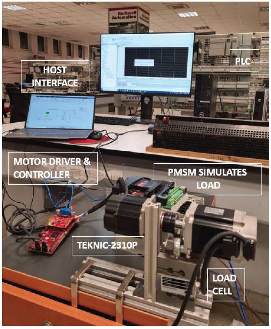
Test system for PMSM drive. PMSM: permanent magnet synchronous motor.
The configuration parameters are modified in the Hardware Settings tab to implement the model created in the simulation on the microcontroller. The desired CPU clock of the TMS320F28379D devices is 200 MHz. The maximum operating frequency of the ADCCLK of the TMS320F28379D devices is 50 MHz. Therefore, the ADC clock frequency in MHz is 40 MHz, which is lower than the maximum operating frequency. The target model created in MATLAB Simulink is divided into four main blocks: Hardware Interrupt, Serial Receive, Speed Control, and Current Control.
The Hardware interrupt block creates the interrupt service routine that runs the model subsystem. The SCI Receive block configures the serial communications interface of the C2000 MCUs to receive data from the SCIRXD pin. The current control block first selects the F2837xD compatible ADC blocks and the enhanced quadrature encoder pulse module. The ADC block is used to read an ADC channel. The motor starts in an open loop and switches to a closed loop when the index pulse is detected in a quadrature encoder based position sensing system. The quadrature decoder is then used to calculate the angular position. Current controllers are placed in the target model and the d–q axis reference voltage is limited at the output of the PI current controllers. The inverse Park transform is used to apply two-axis quantities of an orthogonal reference frame and the space vector generator generates the reference PWM duty cycles from α–β quantities. The target PWM counter period is 5000. Debug signals include the speed response, the stator currents, the d–q axis voltage, the currents and the rotor electrical position. The setup is integrated with load cells to measure the torque applied by the motor under the load. The motor torque response under the load is plotted by extracting data using the PLC.
This section presents the real-time motor performance results for both the PI and ANFIS controllers at no load conditions at 3000 rpm and under load at 2000 rpm. When the motor is running at a constant speed, the speed, torque, stator currents, and d–q axis currents and voltages of the motor are derived. Figure 8 shows the real-time speed responses at 3000 rpm under no load for both controllers. As can be seen, the ANFIS controller which anticipates the future response by using an offline algorithm, is quite effective in reducing the overshoot. The ANFIS control design, which is derived from the conventional PI control, drastically reduces the overshoot to 1.57% compared to the PI control’s response of 6.17%. The ANFIS controller settles quickly in the determined bounds compared to the PI controller. The settling times of the ANFIS and PI controllers are 0.136 and 0.211 s, respectively. The d–q axis currents and voltages are shown in Figure 8(a), (b), (c), and (d) for the PI and ANFIS controllers, respectively, for the same operating conditions. The ANFIS controller keeps the d–q axis variables within defined limits with a shorter settling time and eliminates unwanted oscillations. Figure 8(g) and (h) are used to compare the motor torque and the ANFIS has a sharp transient response by capturing the steady state characteristic earlier than the PI. However, it has a higher torque ripple than the conventional methods. The ANFIS controller draws less current than the designed PI controller at the start of motor operation as can be seen in Figure 8(i) and (j).
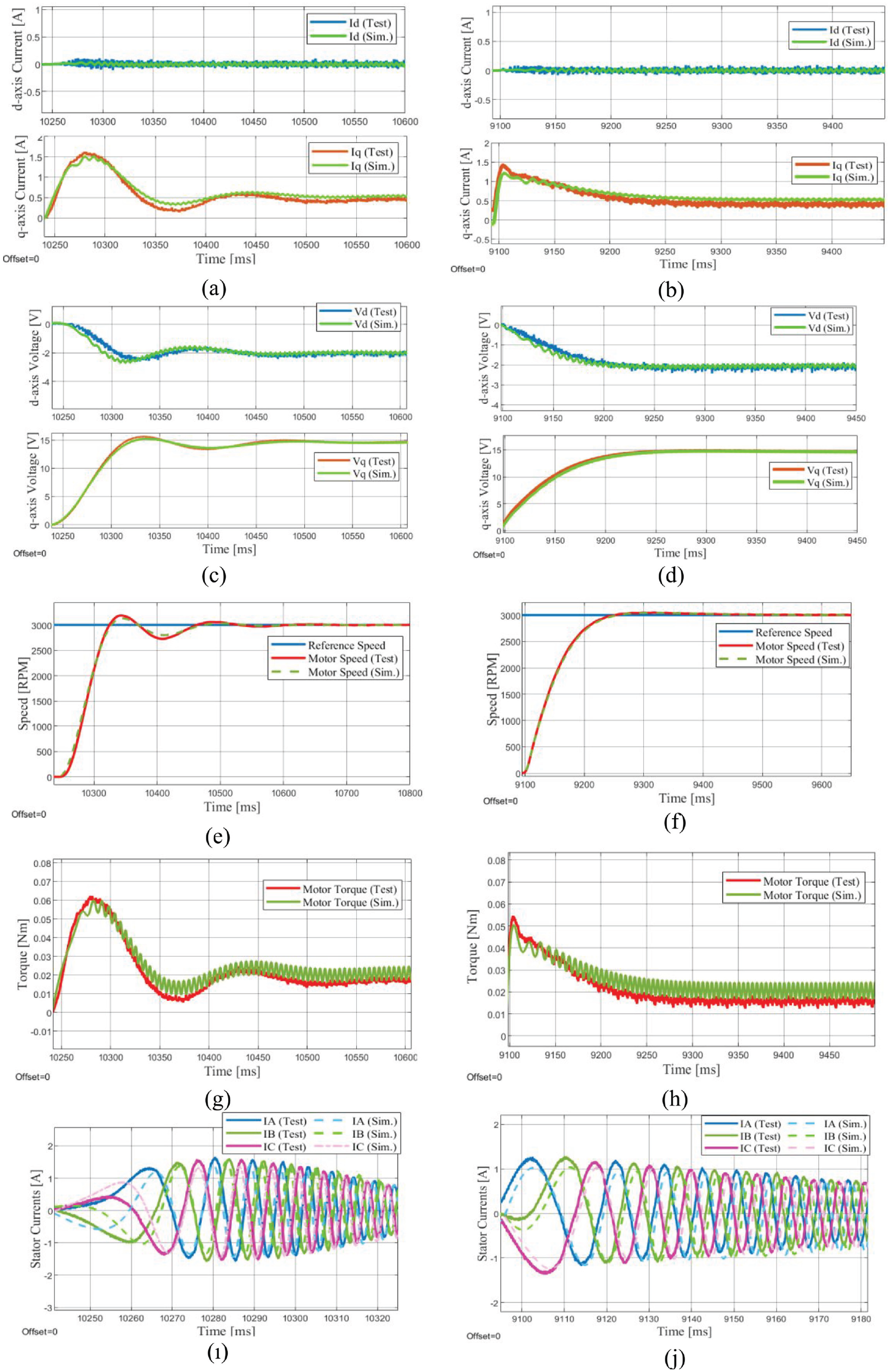
The comparison of the simulation and experimental results at no load condition at 3000 rpm (a) d–q axis currents using PI, (b) d–q axis currents using ANFIS, (c) d–q axis voltages using PI, (d) d–q axis voltages using ANFIS, (e) speed with the PI, (f) speed with the ANFIS, (g) motor torque using the PI, (h) motor torque using the ANFIS, (i) stator starting currents using PI, and (j) stator starting currents using ANFIS. ANFIS: adaptive neurofuzzy inference system.
Figure 9(e) and (f) compare the speed tracking performance results of these controllers under the load condition. While the settling time of the ANFIS controller is 0.31 s, the settling time of the PI controller is 0.77 s. The ANFIS also offers a minimized overshoot of 6.25% compared to that of the PI controller of 36.3 s. The corresponding motor torques of both controllers are shown in Figure 9(g) and (h), respectively. It is clear that the PI controller introduces unwanted oscillations in the transient region. Figure 9(a) to (d) show the d–q axis currents and voltages of the PI and ANFIS controllers. It can be seen that the ANFIS controller removes the d–q axis oscillations and provides very smooth responses. Referring to Figure 9(i) and (j), the stator current of the PI controller is significantly higher than that of the ANFIS.
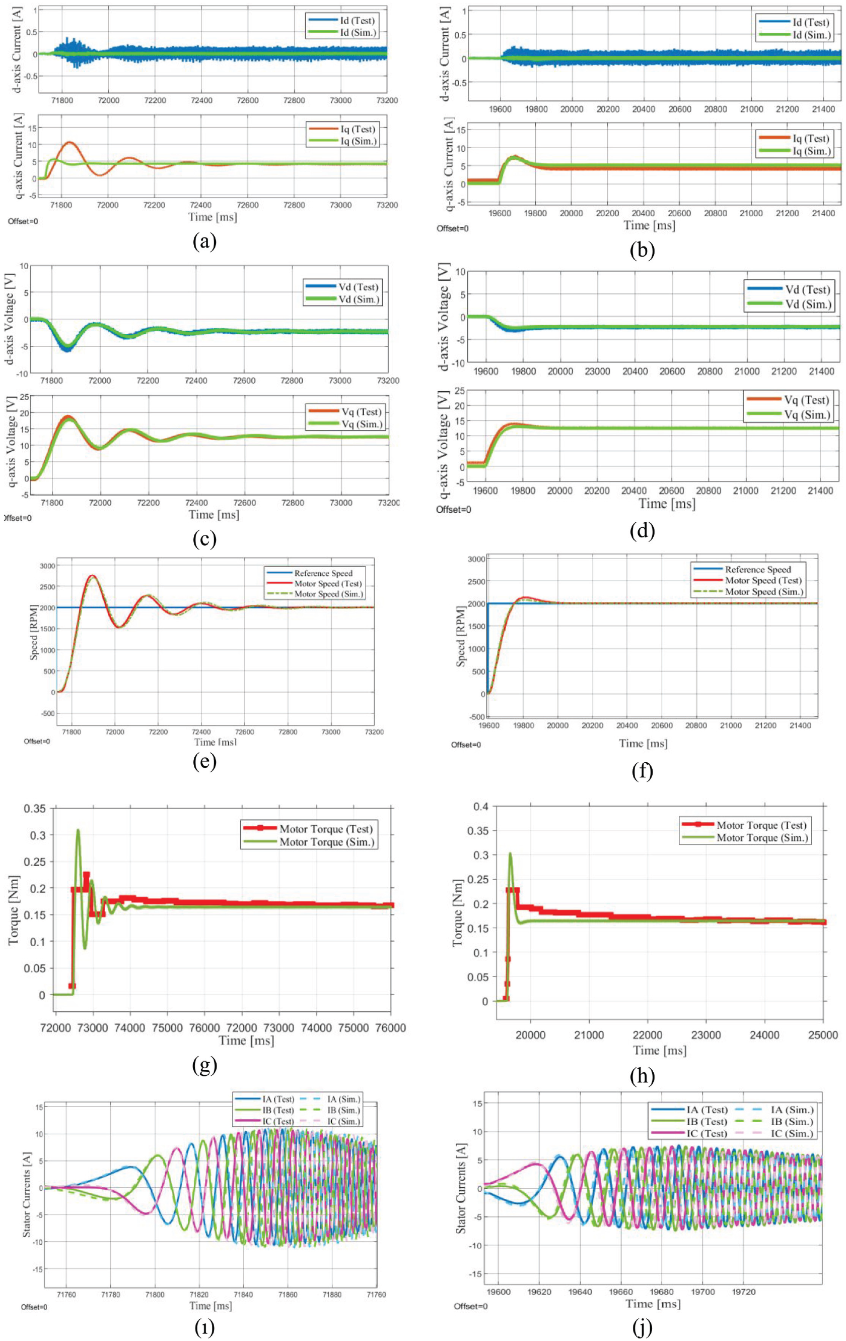
The comparison of the simulation and experimental results under the load at 2000 rpm (a) d–q axis currents using PI, (b) d–q axis currents using ANFIS, (c) d–q axis voltages using PI, (d) d–q axis voltages using ANFIS, (e) speed with the PI, (f) speed with the ANFIS, (g) motor torque using the PI, (h) motor torque using the ANFIS, (i) stator starting currents using PI, (j) stator starting currents using ANFIS. ANFIS: adaptive neurofuzzy inference system.
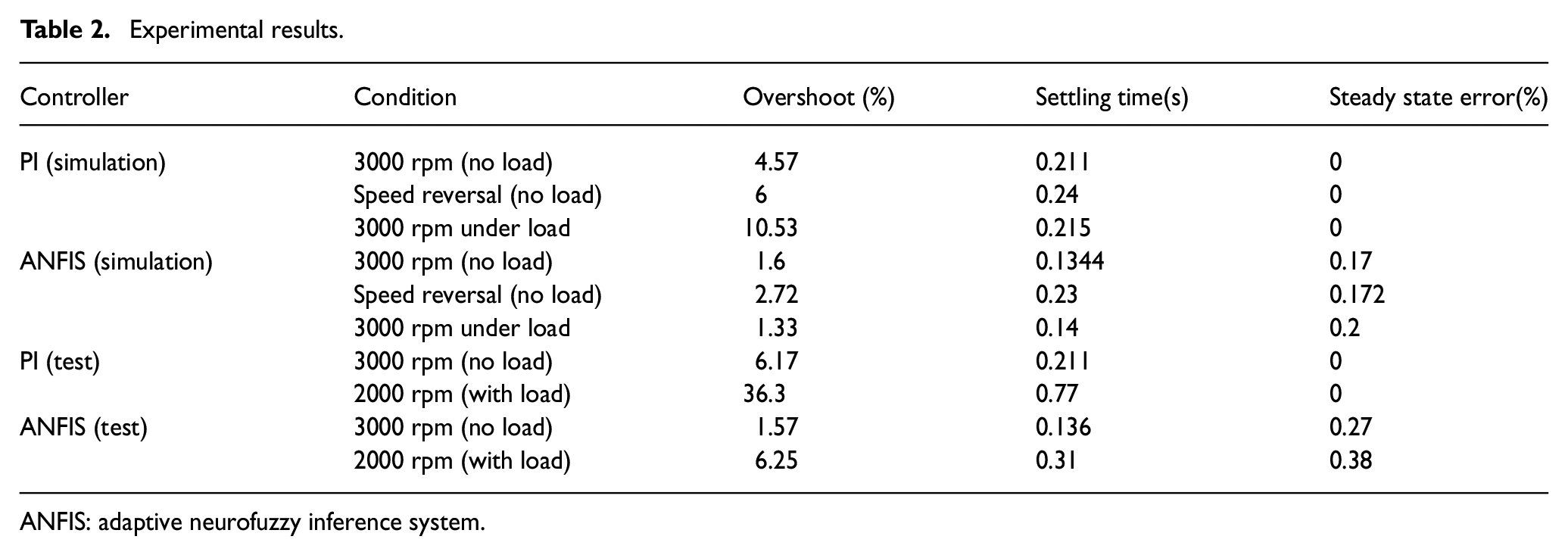
All the simulation and experimental results are summarized in Table 2.
Experimental results.
ANFIS: adaptive neurofuzzy inference system.
ANFIS parameters for input 1.
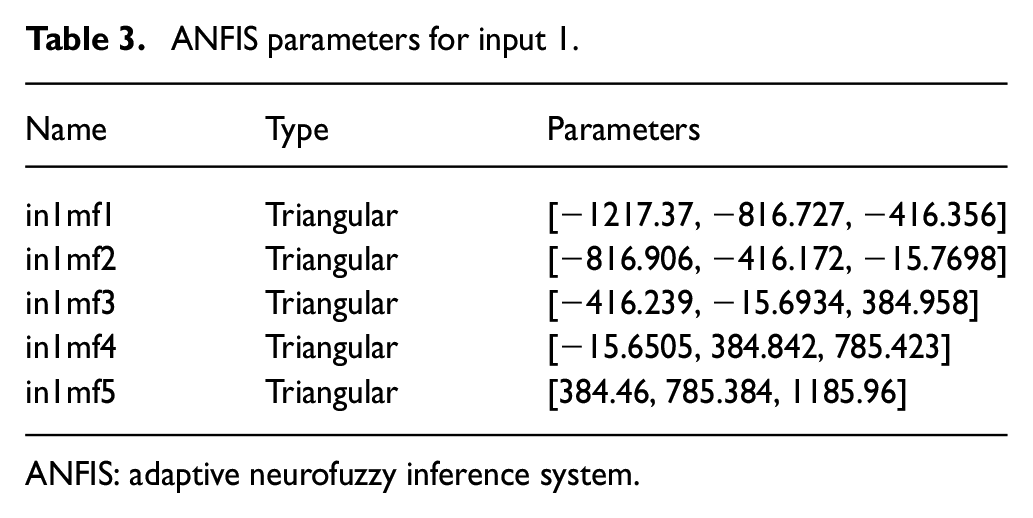
ANFIS: adaptive neurofuzzy inference system.
ANFIS parameters for input 2.

ANFIS: adaptive neurofuzzy inference system.
ANFIS parameters for output.
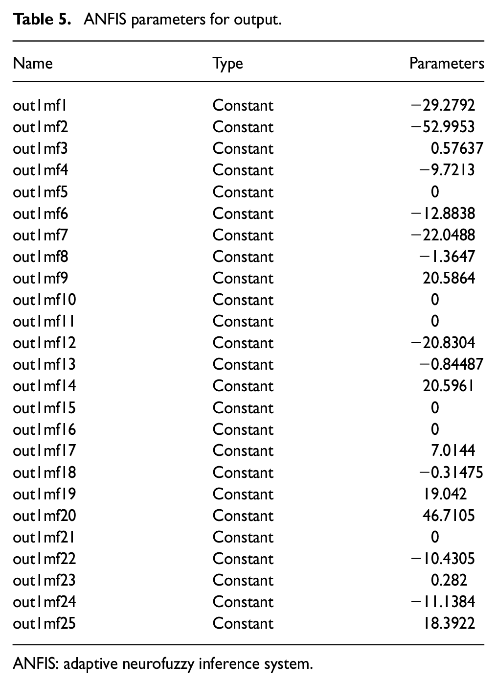
ANFIS: adaptive neurofuzzy inference system.
Conclusions
A new control method based on ANFIS is developed for PMSMs for multicopter applications.
The ANFIS system proposed in this article requires training data extracted from a PMSM dynamic model with a conventional PI controller to achieve better motor performance. A comparative analysis of the ANFIS and PI controllers is carried out through simulation and testing under different speed and load conditions.
It proves that the PMSM drive model is highly accurate, as the simulation results of the ANFIS controller are very close to the real-time performance results for the 3000 rpm at no load condition. The ANFIS controller shows a more robust performance as it adapts and learns most of the motor dynamics and removes the external effects. In real time, the ANFIS controller has drastically reduced the overshoot (in the 2% error band). In addition, the ANFIS controller significantly reduces the settling time compared to the PI controller. By using the ANFIS controller, the overshoot is reduced from 6.17% to 1.57% at no load, from 36.3% to 6.23% at load, and the settling time is almost halved in both cases compared to a conventional PI controller.
Compared to a PI controller, the ANFIS controller has a steady state error of only 0.30%, which is negligible for multicopter applications. Furthermore, the results indicate that the ANFIS design provides a shorter settling time compared to the PI controller.
In the limitations of ANFIS, the training data required for ANFIS is more time consuming, and the selection of the number and type of MFs is crucial to minimize training errors. The most suitable configuration of MFs requires extensive experimentation. ANFIS relies heavily on the availability of accurate data. Performance degradation is highly correlated with data quality, environmental conditions and speed range. Determination of an excessive number of MFs also leads to unavoidable overfitting. The sampling time for speed control of SPMSMs can be measured in microseconds to increase accuracy. However, computational complexity and latency issues may be a drawback. ANFIS is highly sensitive to initial conditions in dynamic systems. Therefore, it requires calibration and saturation blocks.
Footnotes
Declaration of conflicting interests
The authors declared no potential conflicts of interest with respect to the research, authorship, and/or publication of this article.
Funding
The authors received no financial support for the research, authorship, and/or publication of this article.
Data availability
The data used to support the findings of this study are included within the article.