
Abstract
This paper presents a novel control approach for integrated converters using Exact Tracking Error Dynamics Passive Output Feedback control and Exact Static Error Dynamics Passive Output Feedback control. By continuously injecting active distributed power systems (DPS) power sources into the utility grid and loads, the approach reduces harmonic current distortion and maintains unity for the grid’s power factor. The paper compares existing control methods, such as P, PI, proportional–integral–derivative (PID), energy structuring and damping infusion and interconnection and damping assignment—passivity-based control and considers the impacts of instantaneous fluctuations in reference current elements on the AC side and oscillations in DC voltage generated by the DC-link voltage. Relevant switching state functions are designed, and if the maximum power can be fed exceeds the required power from grid-connected loads, the true, reactive, and harmonic current elements of loads are adjusted dynamically, resulting in in-phase sinewave grid currents. The performance analysis is performed using MATLAB/Simulink, and a smaller research prototype is built and discussed.
Introduction
The integration of distributed power systems (DPSs) provides a more flexible distribution system with improved reliability, self-healing, increased efficiency, and lower cost. Moving the sources closer to the loads improves the voltage profile, increases reliability, and reduces transmission and distribution bottlenecks (Jaiyi et al., 2008). A microgrid (MG) can supply essential services to the distribution system and the consumers’ critical demands. They serve as the foundation for upcoming smart grids. Local power systems of various sizes, called MGs, are distributed system components. Each MG consists of a set of interconnected loads and DPS interacting with the grid as a single, controllable entity (Basak et al., 2012). A thorough review of the MG concept, concentrating on low-bandwidth (LB), wireless (WL), and wired control approaches and including idea’s definitions, difficulties, benefits, components, architectures, communication systems, and control methods (Abbasi et al., 2023; Khaleel, 2023), gives a summary of recent developments in intelligent control techniques used in MG, such as neural networks, model predictive control, game theory, deep reinforcement learning, and Bayesian controllers. It also discusses the benefits and drawbacks of these techniques, emphasizing the difficulties in applying them to MG systems. It presents findings from a review of the literature on the performance of intelligent control approaches in MG systems and offers insights into how well they may raise the stability, dependability, and energy efficiency of MG systems.
The technical challenges associated with controlling a sizable number of distributed energy sources are a key barrier to high DPS penetration. It makes the control design and operation challenging. The complex control system has a fundamental problem in addition to the cost. The system will be down due to a software error or a failure in a control component. No matter how complicated the control of the DPS elements in the framework, a suitable control method for multi-DPS elements in an MG produces an autonomous utility grid support network with full load reduction and improvement of power quality and fidelity. Their ability to perform islanding operations in times of crisis increases the resilience and dependability of the electric energy supply. It offers a way around the problems of combining DPSs and renewable energy sources. In actual implementations, knowing how to use dynamic resources and using the suitable analytical approaches to MG result in a flexible and intelligent distribution system. These concepts also provide substantial challenges for MG stability evaluation and control development (Nikos Hatziargyriou, 2014). MG technology has a number of difficulties, such as high startup costs, technological complexity, regulatory difficulties, connectivity problems, maintenance needs, and operational requirements. Sulman Shahzad et al. (2023) intend to offer important insights into the approaches and technologies necessary to meet these issues through a thorough investigation of many research fields and technical elements of MG development.
The management and operation of the entire power network will experience issues as the number of MG DPS elements increases. Therefore, DPS unit control is crucial in MG systems for synchronizing electricity between the grid, load, and DPS sides. To increase the MG’s behavior and stability, several control loops are employed (Monesha et al., 2016). Voltage/amplitude, current, true and reactive power, and frequency/angle are the primary feedback parameters used in the current MG regulating cycles in grid-connected and islanded modes. Modernizations in MG regulation increase its capacity to be fully integrated with traditional electrical systems. Many control mechanisms have been created to govern DPS elements in the MG as a significant part of the modern grid network. Mehrasa et al. (2015) suggested a power-based control method injecting true and reactive power into the utility grid. This makes the connected power converter act like a synchronous power generator.
Since they act as the electronic interfaces between DPS and the electrical network, energy converters are crucial for energy conversion and voltage stabilization. The overview of power converter regulation in MGs, together with problems, solutions, and potential directions for the future, is covered (Hu et al., 2022). The swarm optimization algorithm creates the conventional droop variables and the L1 theory of control such that multiple DPS MGs function appropriately in grid-connected and islanded modes (Chung et al., 2010). Numerous control strategies, including power management strategies (Katiraei and Iravani, 2006), potential-function-based methods (Mehrizi-Sani and Iravani, 2010), unit output power control method (UPC) and Feeder flow control method (FFC) (Ahn et al., 2010), and other potential control methods (Abusara et al., 2014), have been developed for the regulation of DPS elements in the MG, a significant component of the modern grid network.
To improve the frequency dynamic performance of interconnected multi-source power systems composed of thermal, hydro, and gas power plants and the high penetration level of wind energy, an intelligent control strategy is proposed that combines fuzzy logic (FL) control with a proportional–integral–derivative (PID) controller and tuned using arithmetic optimization algorithm (Elkasem et al., 2021). The suggested hybrid power-generating system model using a PI controller is validated to the steady dynamic responses of supercapacitors (Amir et al., 2022). Mishra et al. (2022) examine the effectiveness of a hybrid renewable generation system (HRGS) that uses a dynamic voltage restorer (DVR) to improve the grid’s voltage profile. To assess the performance and stability of the system, various shunt fault and power quality concerns are validated. Khaizaran Abdulhussein Al Sumarmad et al. (2022) introduce an MG system, provide an overview of local control in MGs, and describe an effective energy management system (EMS) for MG operations employing three smart controllers (PID, artificial neural network (ANN), and FL) for achieving optimal MG stability. To maximize the power exchange with the grid configuration, an energy regulation strategy should be designed. A rethink and improvement of the current EMS is required. Many types of control strategies for MG control are briefly described (Monesha et al., 2018), and the various types of MG, the various control methods used in MG, the requirement for earthing and its types, energy management concerns, and the IEEE and IEC standards used in MGs are reviewed (Monesha and Ganesh Kumar, 2020). The creation of a passivity-based control using Exact Tracking Error Dynamics Passive Output Feedback control (ETEDPOF) and Exact Static Error Dynamics Passive Output Feedback control (ESEDPOF) for the reliable operation of MG is, therefore, the contribution of this work.
Harmonic pollution can be caused by non-linear loads being linked to the power grid and drawing non-linear current from the main grid (Pouresmaeil et al., 2018). The harmonic current elements’ passage through the protection network and feeder components results in electromagnetic dispersion and Joule losses, that can intervene with other grid-connected components and impair the operation of the protection network and control circuit for the entire system. Mehrasa et al. (2014) suggest that a direct Lyapunov control (DLM) control technique for a 1Φ grid-connected photovoltaic (PV) inverter was modeled for control system stability, and true and reactive power control, and a control technique for a 3Φ grid-connected PV inverter was suggested for applications of MG to control true and reactive power of the grid and reduce harmonics in grid current. To demonstrate the reliability of the heuristic-adaptive dynamic programming (HDP) power-sharing control in islanded MGs, stability analysis using the Lyapunov theorem is carried out (Sun et al., 2022). The analysis results are validated by simulation studies, which further demonstrate that the HDP-based power-sharing control can successfully operate in the presence of ambiguous load disturbances. Tang et al. (2022) discuss an improved equal area criterion (IEAC) introduced for the study of transient stability of a conventional MG designed with grid-forming and grid-following converters.
Section “Mathematical modeling and analysis of an MG” will give the general illustrative design of the suggested model of MG and discuss the results of the described control scheme. In MG systems with grid interfaces, this paper suggests a novel stability strategy for stabilizing DPSs. The principles of Port-Hamiltonian systems and passivity in physical systems were used to construct this stability technique, which will be discussed in section “Control design based on conventional and passivity.” The advantages and disadvantages of the conventional method and proposed method are given in section “Conventional control versus PBC” and the main limitations of the proposed method are also discussed. The DPS elements can be stabilized using an energy-shaping and energy-damping control strategy according to the unique stability approach. The development of the ETEDPOF approach, which is used to stabilize the MG, was justified by the stability assessment. The framework is modeled in MATLAB/Simulink, and the behavior of the designed controller is analyzed to that of the Existing Energy Structuring and Damping Infusion (ESDI) and Interconnection and Damping Assignment—Passivity-Based Control (IDA-PBC) control schemes. The ESEDPOF method, which evolved from the ETEDPOF method, is also simulated. The switching state specifications of the integrated converter will be examined using the designed model in steady-state operating conditions. The effectiveness of the suggested control method for grid-integrated converters to ensure the stability of the main grid with DPS is demonstrated by simulation results in section “Simulation results.” The suggested control method performs true and reactive power regulation, achieves sinewave voltage at the Point of Common Coupling (PCC), and lowers the grid current total harmonic distortion (THD) in static and dynamic operating conditions and verified experimentally in section “Experimental results,” future studies are discussed in section “Future Studies” and certain conclusions at the end.
Mathematical modeling and analysisof an MG
This section presents the design methodology of the MG system under study. Figure 1 displays the single-line schematic design of the suggested MG framework, which consists of three DPS elements with various loads and local power generation. A static transfer switch (STS) is used to isolate and link the DPS elements to the PCC. As long as the DPSs are not switching from isolated mode to grid-connected mode, the power grid, which is linked to the PCC, provides grid load. When an unexpected load rise occurs, the DPS elements are programmed to feed their maximum true power while linked to the grid. The control of the MG, which is the focus of recent years of research, is the key component of an MG’s stable operation.
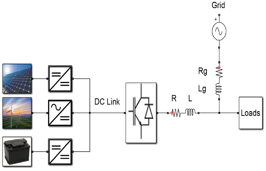
Standard configuration of the proposed framework of an MG.
Mathematical representation is widely used to model systems and dynamics. Typically, the mathematical models or system models reflect the operating specifications of actual systems
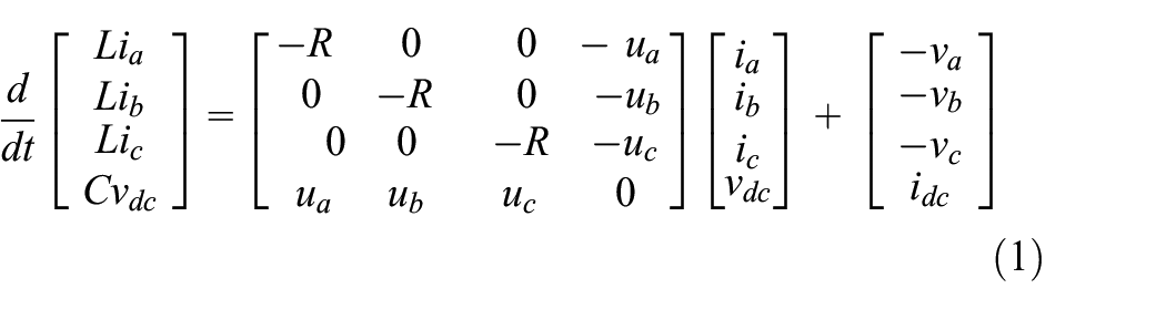
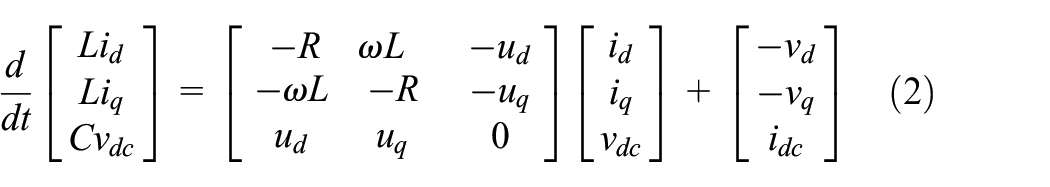
Consider Figure 1, the integrated converter dynamic model built on the d-q elements of its current can be operated as shown in equation (2)
Control design based on conventionaland passivity
Many physical systems have a fundamental characteristic known as passivity, which can be characterized in terms of energy transformation and dissipation. In the sense that it quantifies and characterizes the energy balance of a system when it is stimulated by external inputs to produce some output, it is an intrinsic input–output feature. Passivity is thus linked to the quality of stability in an input–output sense, where we say that a system is stable if “input energy” is fed to it output energy with a finite range. In other words, the degree to which a system deviates from the performance that is desired. A process known as passive-based control entails regulating a system with the goal of making the closed-loop system passive.
ESDI
ESDI uses Lyapunov’s stability criteria for shaping and damping energy and makes the system suitable for controlled and stable operations. For the desired time interval and desired energy rating, the system is operated without cumulative damping errors, making the system more stable compared to all feedback systems. Tuning the circuit for open loop and closed loop with minimum damping coefficient is possible, thus making the energy grid more stable and preferable for all types of distributed generation and transmission in the open environment.
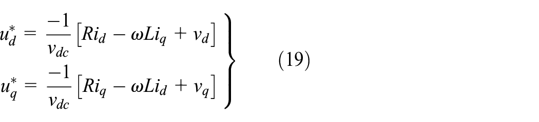
This strategy involves injecting the proper series damping resistances into each component of the DPS elements to reduce the cumulative energy stored by the MG to nil or a bounded value in state variable paths in the MG system, followed by energy shaping. Consequently, depending on the reference and fault state variables, damping resistances are added to equation (2) to produce
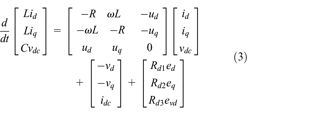
where
and
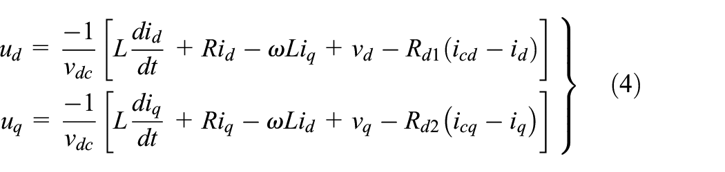
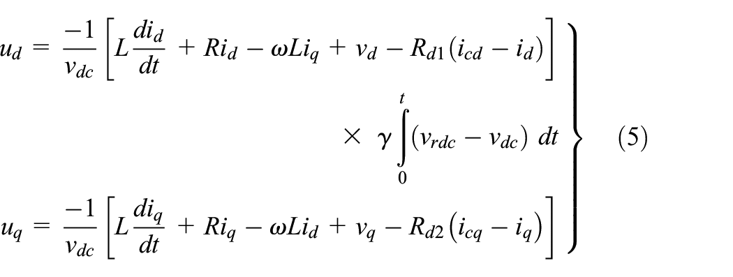
IDA-PBC
We already know that an integrator can enhance the steady-state behavior of a plant. The IDA-PBC must incorporate an integral action to guarantee zero steady-state error. The integral action of the IDA-PBC can thus be taken into account in d-axis controller (4). The controller equation’s q-axis equation remains unchanged. According to LaSalle’s Principle, the value of
ETEDPOF
Using this technique, the system steady-state response is calculated for full load analysis. It is used to analyze the stabilization with exact error dynamics. The feedback obtained in this method will have a generalized Hamiltonian form with output conditioning of finite error values. In case of energy dissipation, the feedback circuit will have larger error values and a quick tracking scheme will be adopted. It helps in achieving a smooth start.
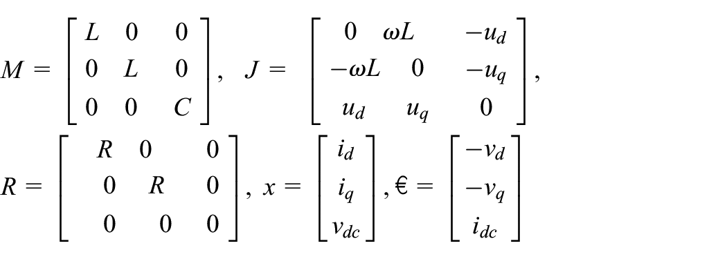
According to Mehrasa et al. (2014), the average model can be represented by

where
for all
Also,
Assume that

Defining the tracking error state and the error of average control as
Using equations (6) and (8), the following exact tracking error dynamics are obtained

which after substituting equation (4), can be written as
where
Proposing a feedback control for the passive output associated with equation (9) is defined by

where

To verify the stability of equation (12), the following energy function is proposed
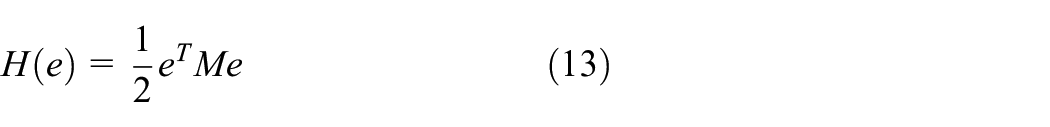
leads to

If
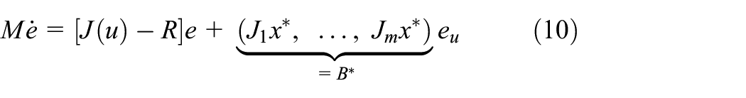
Applying the general results of the ETEDPOF method in the system, the dynamics of the error of Exact tracking for equation (3), explicitly, is
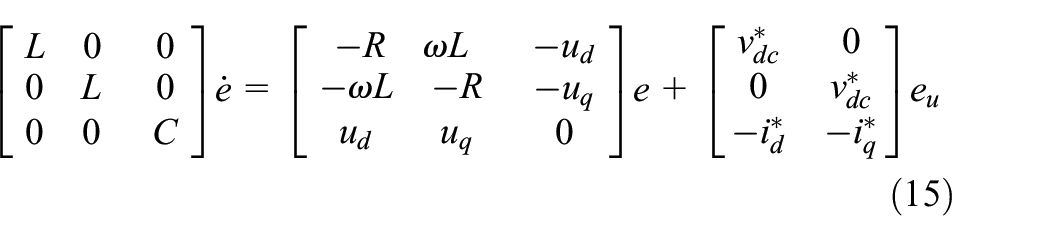
where
While the control by ETEDPOF, according to equation (10) and the constraint is satisfied, is determined by
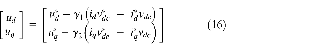
where
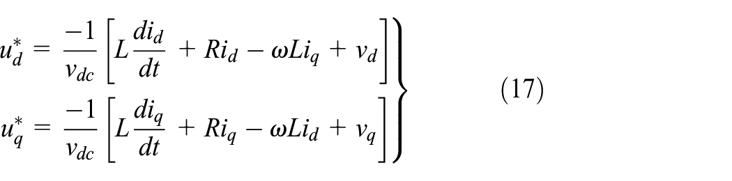
Equation (16) maintains closed-loop stability control during dynamic transitions. A key component for enhancing grid current THD with a quick dynamic response during load fluctuations is the positive constant coefficients of
ESEDPOF
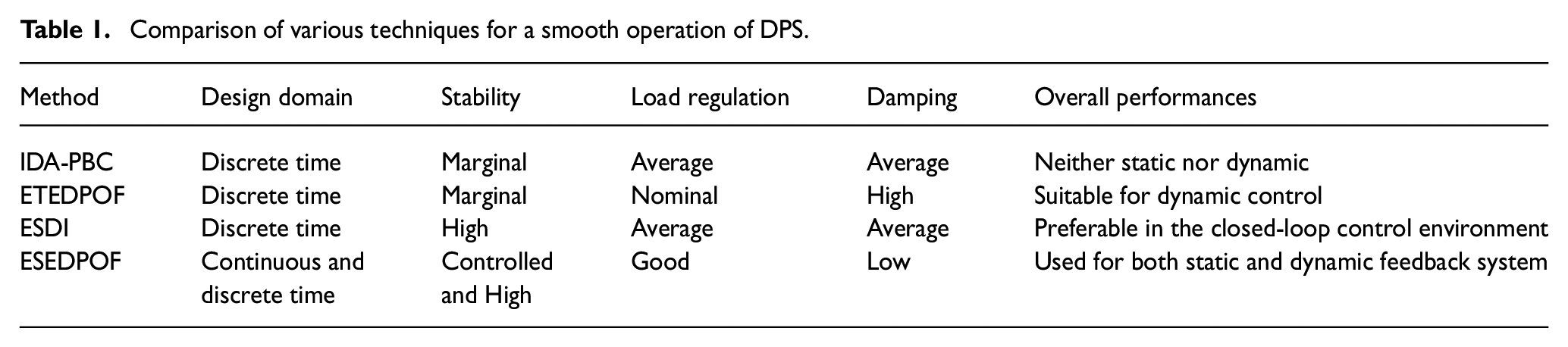
The system is mainly inducted with a load compensation scheme for proper and quicker response time and recovery factors. DPS operations are closely altered due to frequent load imbalance and damping factors. The control scheme in the ESEDPOF works well in combination with PBC when the whole system runs in closed-loop feedforward conditional margin with rated operating frequency. Table 1 shows the comparison of various techniques for a smooth operation of DPS. The control by ESEDPOF is determined by
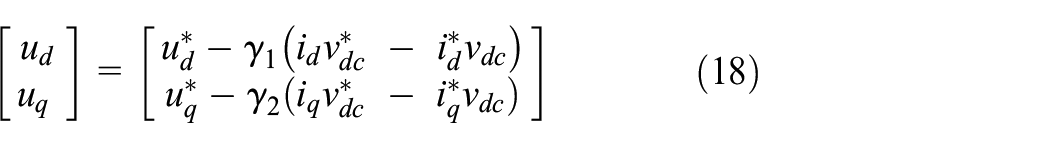
where
Comparison of various techniques for a smooth operation of DPS.
Conventional control versus PBC
Conventional control
Advantages
Simple to implement;
System dynamics are not necessary for realization;
Just two/three variables need to be optimized.
Disadvantages
Cannot guarantee the robustness of closed-loop systems;
Cannot eliminate steady-state errors for sinusoidal signals;
Unable to adjust for changes in load.
PBC
Advantages
Identifies, controls, and optimizes the system’s parameters;
Better control over voltage and frequency, and power sharing among several MGs.
Disadvantages
The construction of the model is intricate;
A top-notch processing unit is necessary;
The process takes a long time.
Limitations
The two requirements that are most important are that the system’s zero dynamics must be stable and that the output we describe must have a relative degree no higher than one. Due to the fact that feedback cannot change any characteristic, this is quite limiting.
Simulation results
The model proposed in Figure 2 is designed via MATLAB/Simulink and assessed under dynamic and stable operating circumstances. The objectives of the following scenarios are suitable for power sharing and proper frequency and voltage regulation while testing the complex and stable operations of the suggested MG control technique. To get non-linear currents from the source, the non-linear load I, II, and linear load are connected to the power grid and then the DPSs by repeating this process until t = 0.1 seconds. To inject all of their true power and make up for all of the reactive power that the loads are required to supply, the DPS elements are used in grid-connected mode. The DPS unit’s conditions and load communication are frequently adjusted using STSs.
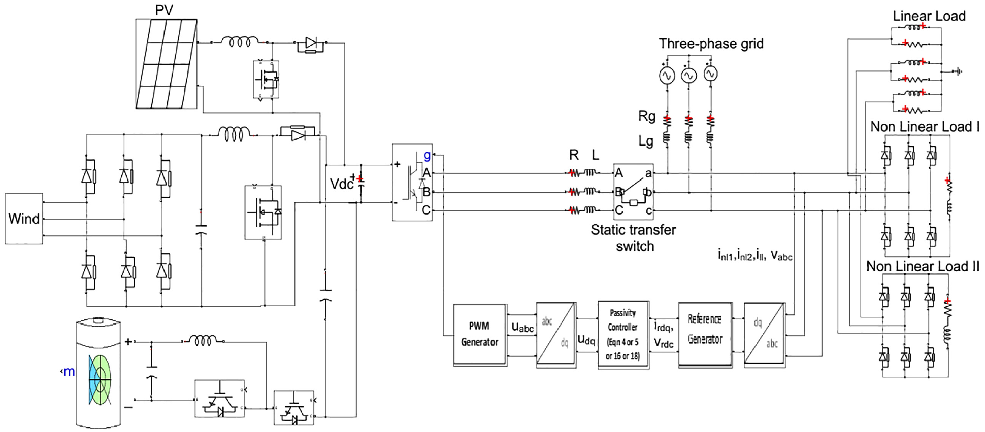
Schematic layout of the proposed framework of an MG.
The MATLAB/Simulink solver configuration parameters are as follows.
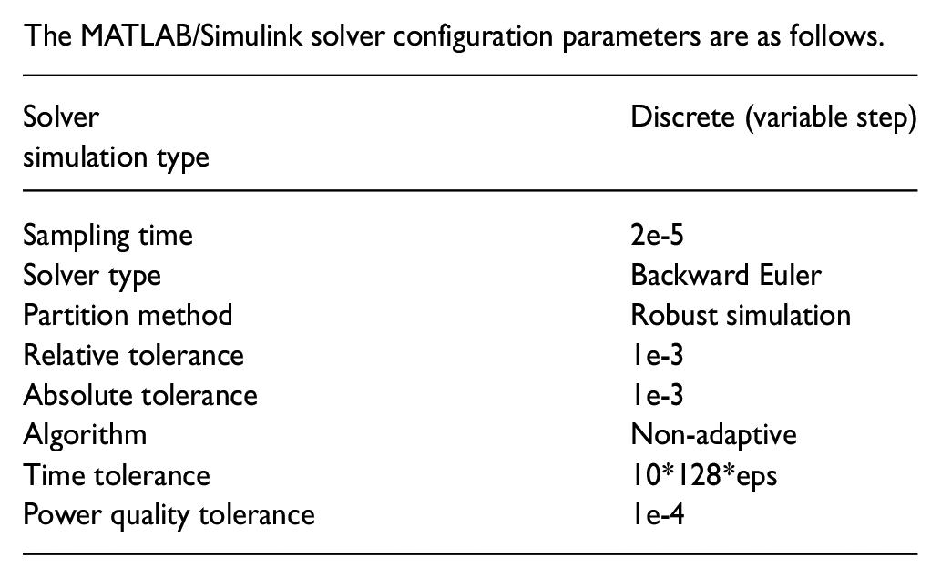
Table 2 lists the values of the parameters for the loads, grid, and DPS elements. The main goal of this part is to examine the capability, adaptability, and resilience of the designed control strategy in guiding the integrated converter to supply the necessary true and reactive power in static and dynamic operational aspects. The effects of harmonic current compensation, power factor (PF) correction, and non-linear load fluctuations on DPS sources’ grid connections are also investigated.
Simulation parameters.
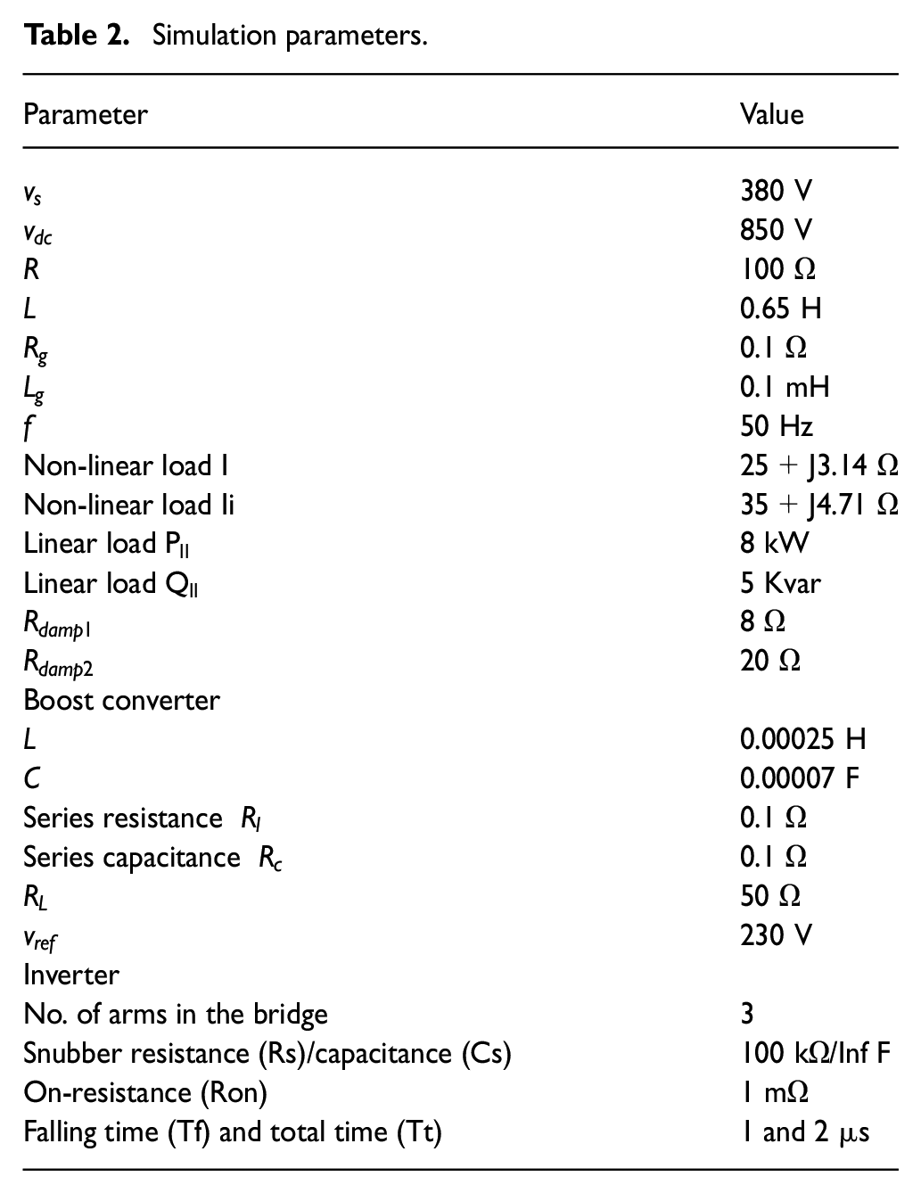
Figure 3 shows the simulation results. Figure 3(a) shows the three-phase PCC voltage. It is stable and balanced in the condition of variability in the load. Figure 3(b) displays the response of magnitude of the PCC voltage, Figure 3(c) displays the response of frequency of the PCC voltage, where frequency with a minimal transient response is held within a reasonable range of changes, Figure 3(d) depicts the true power sharing of the power grid for PI, PID, ESDI, IDA-PBC, ETEDPOF, and ESEDPOF. Figure 3(e) indicates the true power of the linear and non-linear loads. The statistics show that power for the loads is supplied by the power grid before the connection of DPS elements to the grid.
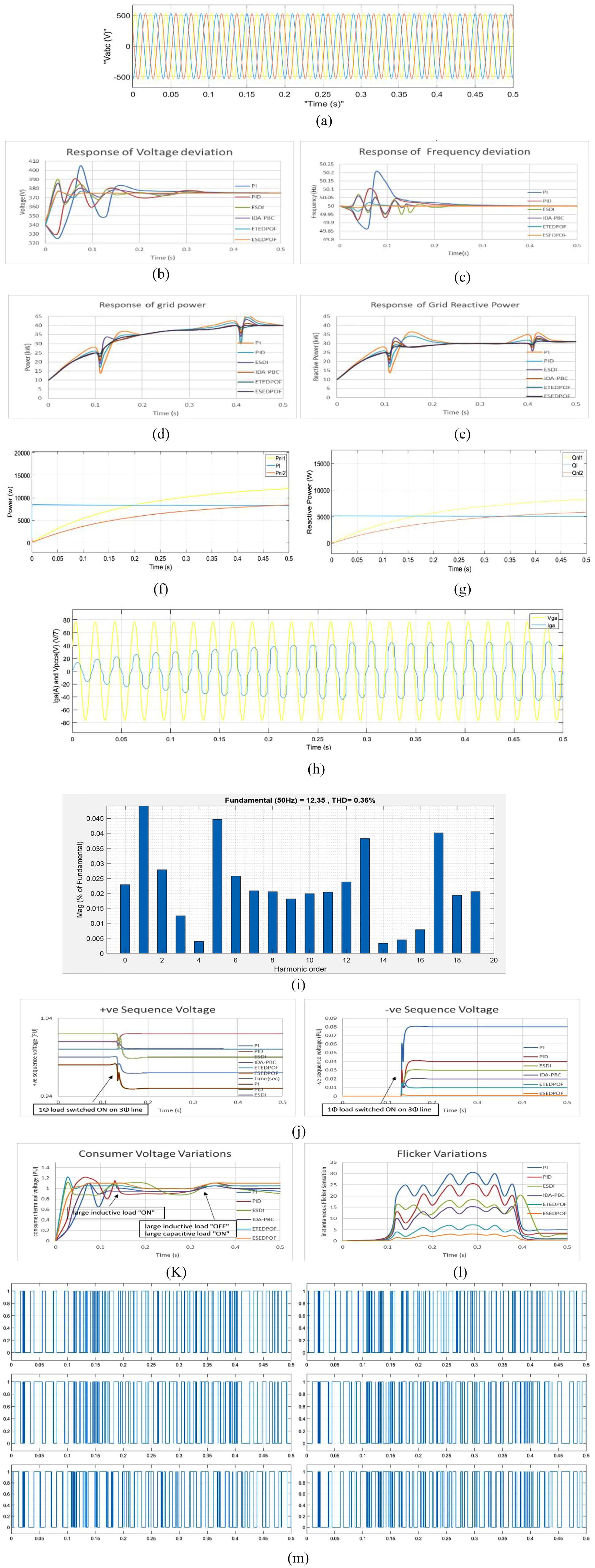
Simulation results. (a) PCC three-phase voltage. (b) Response of voltage deviation. (c) Response of frequency deviation. (d) Response of grid deviation. (e) Response of grid reactive deviation. (f) True power sharing of loads. (g) Reactive power sharing of loads. (h) Phase “a” load voltage and grid current. (i) THD of phase “a” grid current. (j) Voltage imbalance (positive sequence voltage and negative sequence voltage). (k) Overvoltage and Undervoltage (consumer voltage variations). (l) Flicker variations. (m) Controller output curve.
Figure 3(f) and (g) shows the reactive power sharing for the proposed MG model. As shown in figure, all the reactive power is supplied by the utility grid before the connection of DPS units. Figure 3(h) displays the load voltage and grid current at phase “a.” As depicted in this diagram, the grid current is approximately sinewave and in-phase with the load voltage. As a result, reactive power and PF which is unity are derived from the injected grid current, which is free of harmonic current elements. The THD of phase “a” grid current is reduced to 0.36%, as shown in Figure 3(i), indicating that the non-linear grid-connected loads can effectively be compensated for harmonics using the proposed control approach.
At the specified time, a 1-ph load is turned “ON” on a 3-ph line, and sequence voltages are recorded as illustrated in Figure 3(j). Equation (20) can be used to compute the voltage imbalance for PI, PID, ESDI, IDA-PBC, ETEDPOF, and ESEDPOF

Simulating over- and undervoltage involves turning on and off huge inductive and capacitive loads at the same time which are analyzed based on IEC60038 is illustrated in Figure 3(k). IEC61000-4-15 is used to represent flicker. Switching a variable load that draws 20 A at unity power factor (UPF) simulates non-linearity. It is shown in Figure 3(l). Figure 3(m) shows the controller output curve for ESEDPOF which generates the gate pulses for the interfaced converter.
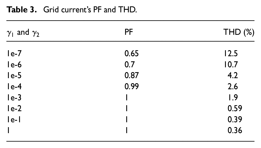
According to Table 3, variations in dynamic gains have an impact on THD and the PF between load voltage and grid current in phase “a.” It shows that the PF improves as the coefficients increase and the grid’s PF approaches unity for increases greater than 1e-4. It can be seen that the value of THD significantly declines as the coefficients rise and stay constant at 0.3% for the last two coefficient values.
Grid current’s PF and THD.
Experimental results
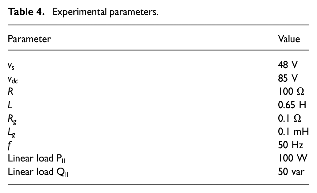
To test the proposed concept, a scaled-down research prototype is built. A three-phase star–star linked transformer with a 230/48 V rating on the secondary side and a 10 A rating on the primary side is used as input for the distributed generation and the grid interface. Table 4 displays the system’s specifications.
Experimental parameters.
The prototype built is shown in Figure 4. The hardware setup is shown in Figure 4(a). The three-phase line-synchronized pulse generator is shown in Figure 4(b). The DPS side-controlled rectifier is depicted in Figure 4(c) and the linear load setup is illustrated in Figure 4(d).
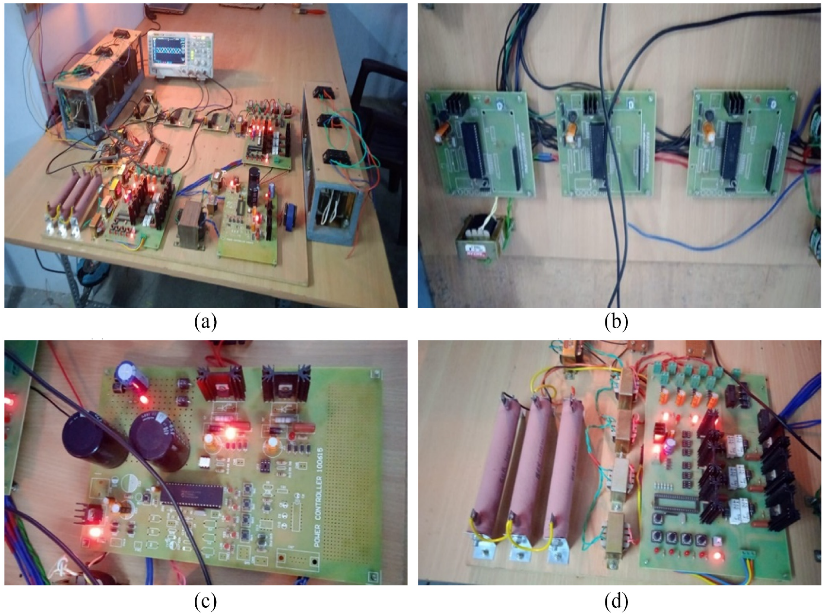
Research prototype. (a) Hardware setup. (b) 3φ line-synchronized pulse generator. (c) DG side-controlled rectifier. (d) Linear load.
Figure 5 shows the experimental results. Figure 5(a) depicts the PCC three-phase voltage waveform. The DC-link voltage waveform is given in Figure 5(b). Figure 5(c) depicts a zoomed view of the DC-link voltage ripple. At the startup, this voltage is very low and is charged by both the renewable voltage channel and the grid. It eventually stabilizes at that point, momentarily disturbed by an abrupt shift in the load side, and the control operation restores its stable value. Figure 5(d) depicts the typical outcomes for the DC-link voltage for the sudden removal of a non-linear load. Figure 5(e) depicts the switching pulses for the top and lower MOSFETs of the converter’s “a” phase. The three-phase non-linear load currents are given in Figure 5(f).
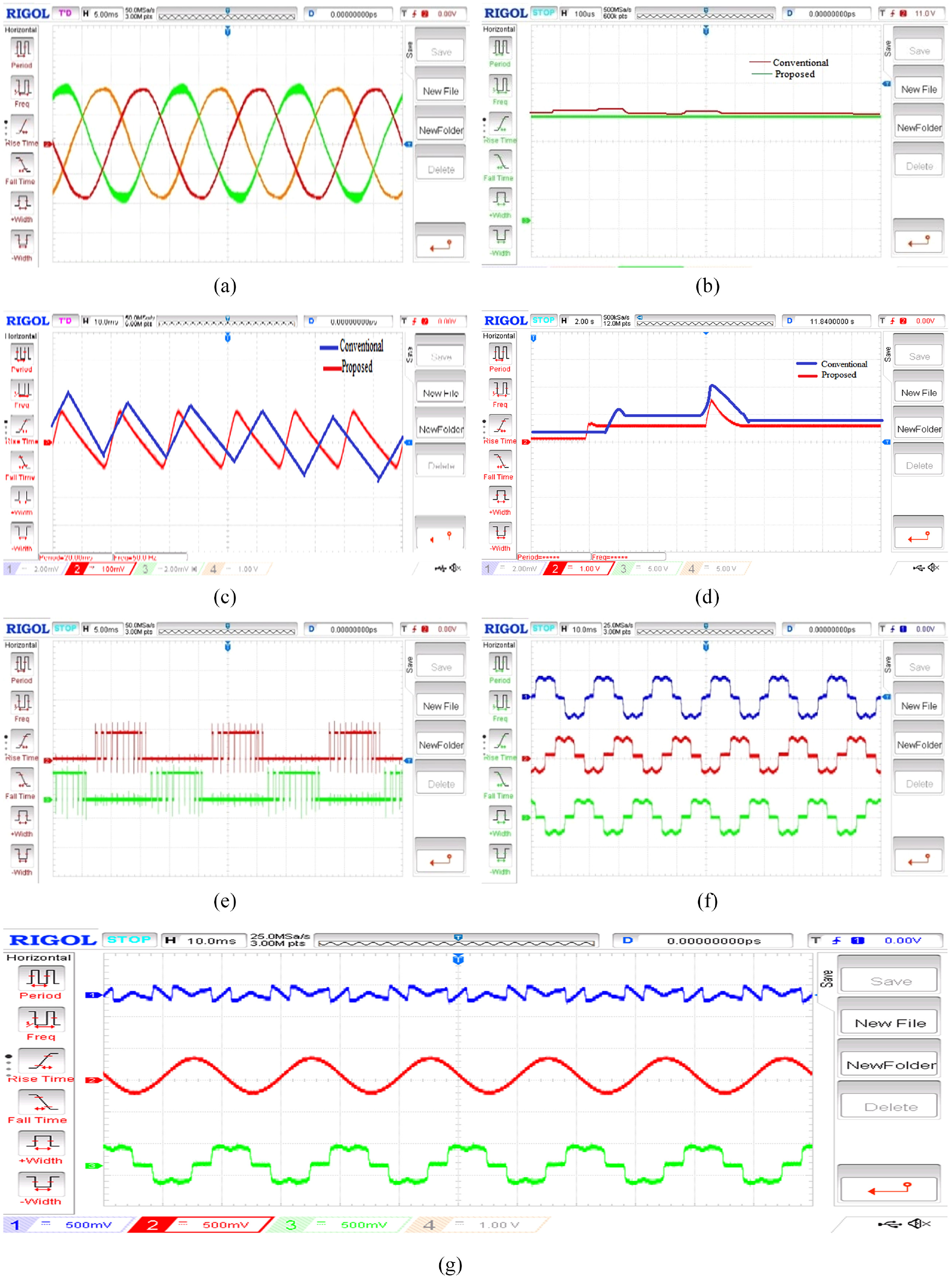
Experimental results. (a) PCC three-phase voltage waveform. (b) DC-link voltage waveform. (c) DC-link voltage ripple. (d) DC-link voltage at sudden removal of load. (e) Switching pulses. (f) Non-linear load current waveform. (g) The injected current, the grid current, and the non-linear load current.
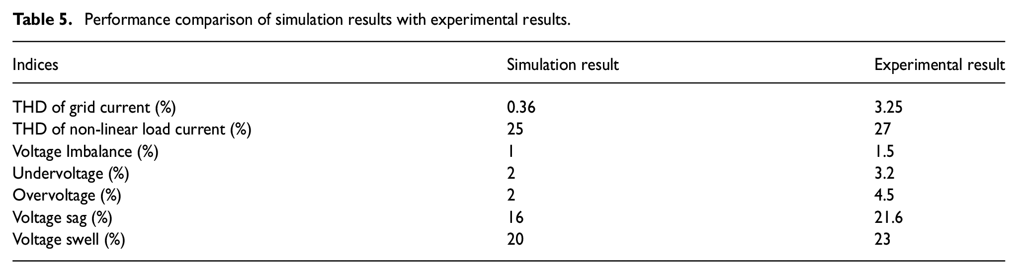
Figure 5(g) shows the non-linear three-phase currents drawn by the 3Φ diode bridge rectifier, the correcting current injected from the 3Φ inverter, and the grid side current. The grid side current has been corrected to be sinusoidal and the THD of grid current THD is found to be 3.25%, while the non-linear load current THD is 27%. Table 5 shows the performance comparison of simulation results with the experimental results.
Performance comparison of simulation results with experimental results.
Future studies
To rectify current harmonics, manage PF, and stabilize PCC supply voltage, the ESEDPOF controller is used as a unique control approach. This has to be tuned as effectively as possible, which may be done using a variety of optimization techniques, such as the Whale Optimization Algorithm, Gray Wolf Optimization, and enhanced versions of these algorithms. These methods enable the proposed controller to be tuned to the optimal value for MG frequency and voltage management. The goal of this is to develop algorithms that can quickly and efficiently search for optimal values to improve controller settings and outcomes.
Conclusion
This work introduces a passive-based control mechanism for the improved functioning of DPS elements based on the ETEDPOF and ESEDPOF techniques. The DPS elements deliver on-demand true power injection from the DPS elements to the power grid. A miniature research prototype is built, and the practical results are conferred, which confirm the performance of the suggested control technique. MATLAB/Simulink model results access the operation of the designed control strategy. Results from simulations have shown that the suggested control approach performs well. The introduced control method ensures no issues with DPS source synchronization to the utility grid. The results revealed that grid current and load voltage are always in-phase, enabling DPS to function as a PF corrector device by raising PCC’s PF. The results demonstrate that DPS can give the harmonic current elements that the non-linear demand requires. The designed control strategy may be applied to various DG elements as power quality enhancement equipment in the main power system based on the performance analysis in terms of power quality. This improves the viability of MG to handle sustained demand and eliminate problems with traditional grids. The energy requirement is met, ensuring safe operation. The MG balance is maintained by maintaining constant DC voltage and AC frequency.
Footnotes
Nomenclature
€ external power supplies to the system
Declaration of conflicting interests
The author(s) declared no potential conflicts of interest with respect to the research, authorship, and/or publication of this article.
Funding
The author(s) received no financial support for the research, authorship, and/or publication of this article.