
Abstract
Quadrupeds are capable of dynamic movements such as fast running and long-distance jumping due to their flexible and elastic torso structures. In this paper, a compliant parallel mechanism is proposed as a bionic torso to simulate the diversified behaviors and agile locomotion of the tetrapod torso. The spring module is incorporated into the limb of the parallel mechanism to absorb external shocks, cushion, and dampen vibrations, thus improving the compliance performance of the bionic torso. For the compliant parallel mechanism, its kinematics and kinetics are analyzed, and the overall electromechanical system and control framework are devised. The multidimensional damping dynamic characteristics of the proposed mechanism are qualitatively analyzed by simplifying the limb into a spring–mass damping system. The parallel mechanism with compliant spring modules absorbs external forces to different degrees with different stiffness coefficients to avoid damage to the structure by external impacts. The parallel mechanism with different initial positions exhibits the inherent variable stiffness characteristics of the mechanism. The parallel mechanism simulates the diverse behavior of the animal torso, with independent and synthesized locomotor behavior of the six underlying motion patterns. Simulations and experiments demonstrated that the compliant parallel mechanism is effective in vibration damping and cushioning, with a rapid response and small steady-state error. The motion of the compliant parallel mechanism in one direction and the motion of the integrated multi-degree of freedom (DOF) are confirmed and exhibited in the behavioral experiment.
Introduction
Inspired by morphology (Yesilevskiy et al., 2018), numerous bionic torsos have been developed to mimic the behavior and characteristics of biological torsos. In nature, the torso of quadruped walking animals connects the forelimbs and hindlimbs, and its central element, the spine, plays a critical role in the dynamic movement (Grondin and Potvin, 2009) of the animal. During the rapid movement of quadrupeds, the spine absorbs the impact and stores a certain amount of elastic potential energy (Alexander et al., 1985; Haueisen, 2011; Hildebrand, 1959) through the synergistic action of the scapula and hip joints, releasing the stored energy to assist other movements when the limbs are airborne. Thus, the spine extends the stride length to enable the animal to move at a faster speed (Kim et al., 2014). In addition, the advantage of multiple degrees of freedom (DOFs) in the spine permits the animal to instantly adjust its posture to avoid danger in an emergency circumstance. Typically, cheetahs are the fastest running mammals (Sharp, 1997) on terrestrial land due to their compliant spine structure with dramatic flexion and extension characteristics. Restricted by the rigid torso, the motion performance of traditional quadruped robots needs improvement. The introduction and study of compliant bionic torsos are necessary to enhance the flexibility, compliance, coordination, and energy efficiency of quadrupedal robots.
Over the past decade, several different classes of bionic torsos have been developed and applied to quadrupedal robots. Among the abundant bionic torso already existing, the most typical is the differential spine of the Cheetah (Seok et al., 2014b) robot developed at MIT. The spine consists of spinal units separated by a polyurethane rubber ring and mimics the vertebrae of a quadruped spine. The sagittal plane of the spine is connected to the robot’s hind limbs by steel cables to produce coupled motion. The elastic elements in the spine can store and release energy from ground contact. The cheetah robot with spinal joints, weighing 33 kg and with an average speed of 22 km/h, has a total transport cost of 0.5, which is comparable to that of an animal of the same size. Another bionic torso that utilizes the same principle is the multi-jointed tandem supple spine of the Lynx (Eckert et al., 2015) quadruped robot. This spine is driven downward by a motor and reversed passively by a spring element. Boston Dynamics developed the Cheetah (Boston Dynamics, 2018) robot with an ultra-high-speed (28.3 mph), whose spine extension and curvature increase the robot’s stride and running speed.
So far, only a few research scholars have initiated studies on adding DOFs to robot torsos, and single-DOF bionic torsos or spines (Khoramshahi et al., 2013; Leeser, 1996; Matsumoto et al., 2019; Phan et al., 2020; Spröwitz et al., 2013; Wang et al., 2020b; Weinmeister et al., 2015) predominate. Among developed bionic torsos, the earliest study is the articulated spine (Leeser, 1996) of a planar quadruped robot at MIT in 1996. Similar bionic torsos and spines include the compliant spine of the Cheetah-cub-S (Spröwitz et al., 2013; Weinmeister et al., 2015) flexing laterally, the articulated spinal joint with passive flexion and extension designed by Wang et al. (2020b), and the two-segment active spine of the Bobcat (Khoramshahi et al., 2013; Pouya et al., 2017). In the evolution of research on bionic torso structures, innovative advances in multi-DOF torso structures have been achieved as well. A spring spine mechanism that permits bending and torsional deformation was presented by Cho et al. (2019). Zhao et al. (2013) exploited a silicon block spine that allows flexible bending around the pitch and yaw axes. A 3-DOF parallel spine designed by Wang et al. (2020a) not only enables pitch and yaw bending but also telescopes in the direction of motion. The 2-DOF articulated torso recently developed by Zhang’s team mimics the flexion and extension motion of the spine of a cheetah during running by two sets of pitching motions (Wang et al., 2022). It is evident that the increase in spinal DOFs facilitates the flexibility and diversity of behavioral movements for the quadruped robot and contributes to the stability of the mechanism. Given that the DOF of the tetrapod torso remains unclear, our objective is to design a 6-DOF parallel mechanism to simulate the multimodal dynamic behavioral movements of the biological torso. In our previous work, kinematic properties comprising structural constraints, three-dimensional motion space, and stresses have been investigated (Qin et al., 2019). The application of nonlinear oscillator synchronization methods (Zhu et al., 2018, 2019, 2020) facilitates the transition and transformation of signals from different kinematic modes. After the fusion of neuromechanical networks (Zhu et al., 2021), the highly coupled bionic parallel torso could generate several different motion patterns and perform the transition of behaviors.
However, the flexibility of muscle tendons should not be dismissed in animal torsos. Researchers have mainly adopted variable stiffness drives (Lei et al., 2022; Reinecke et al., 2021), muscle control strategies (Zhu et al., 2023), or the addition of passive elastic components (Cao and Poulakakis, 2016; Pouya et al., 2017; Pusey et al., 2013), to achieve the compliant behavior of the biological torso. The study of methods of introducing spring elements into the torso has attracted attention but has not yet been widely used. The passive elastic spine of the DCat II quadruped robot reduces foot-end forces and avoids impacts while increasing the robot’s movement speed (Wang et al., 2022). The SQBot robot’s rigid-flexible coupled spine motion with bending and torsion springs is beneficial to the quadruped robot’s motion performance (Chen et al., 2021). As studied by Cao (2016) and Ikeda and Mizuuchi (2017), the torso equipped with passive elastic joints diminished the energy loss during walking of a quadruped robot. The spine mechanism with torsion springs designed by Kawasaki et al. (2016) stored elastic energy efficiently. The spring-loaded spine in the Canid (Pusey et al., 2013) robot absorbed and released elastic potential energy during dynamic motion. However, the 6-DOF parallel mechanism we developed does not yet have the flexibility of a biological torso. Hence, the primary objective of this research is to introduce elastic elements into an active 6-DOF bionic parallel mechanism for simulating a biological torso demonstrating a compliant motion effect. In this paper, we propose a compliant bionic parallel mechanism. With the spring element in each branch chain, the parallel mechanism could absorb external impacts and vibrations, store energy, and release energy to decrease energy consumption. The addition of spring elements will enhance the vibration-damping efficiency of the bionic parallel mechanism, which will be of great interest to the realization of compliant motion. Moreover, the compliant parallel mechanism has variable stiffness characteristics, which adapts to complex movements with different modes at different speeds and facilitates coupling with quadruped robots.
The remainder of this paper is organized as follows: section “Parallel mechanism modeling” explains the kinematics and dynamics of the compliant parallel mechanism. Section “Materials and methods” describes the hardware device and the control framework. Section “Performance analysis” shows the dynamic characteristics of the compliant parallel mechanism. Section “Experiment” presents the experimental results of the dynamic motion of the compliant parallel mechanism. Finally, in section “Conclusion,” the conclusion and future work are given.
Parallel mechanism modeling
Kinematics
The movement of a quadrupedal walking animal is stabilized and coordinated by the flexion and extension of the torso. The animal torso is employed for posture adjustment, external impact absorption, and elastic energy storage and release. Inspired by the characteristics of the biological torso, we propose a 6-DOF compliant parallel mechanism as the torso of a bionic quadruped walking animal, and its structure is shown in Figure 1. The introduction of spring elements is intended to increase the flexibility of a parallel mechanism. The redundant DOFs allow the mechanism for flexible and agile multimodal movements. The bionic parallel mechanism could adequately emulate the bending, extension, and swinging of the bio-torso during fast running. The 6-DOF parallel mechanism consists of six identical limbs, a moving platform, and a stationary platform. Driven by an independent DC brushless motor, each branch chain comprises a limb and a rocker, where the limb is composed of four parts: the upper limb, spring module, force sensor, and lower limb. The connecting rod has a spherical joint on each end, the upper one attached to the moving platform and the lower one attached to the rocker. Each set of upper spherical hinges is evenly spaced 120° apart below the moving platform. At 120° intervals, the motors are distributed on the stationary platform. The force sensor records and feeds back the load on the connecting rod in real time. A magnetic encoder connected to the motor output shaft by a spur gear with an equal number of teeth obtains the motor position information. There is a rotary joint at the output of the motor. The position change of the parallel mechanism is realized by the motor driving the rocker to rotate and actuate the linkage movement.
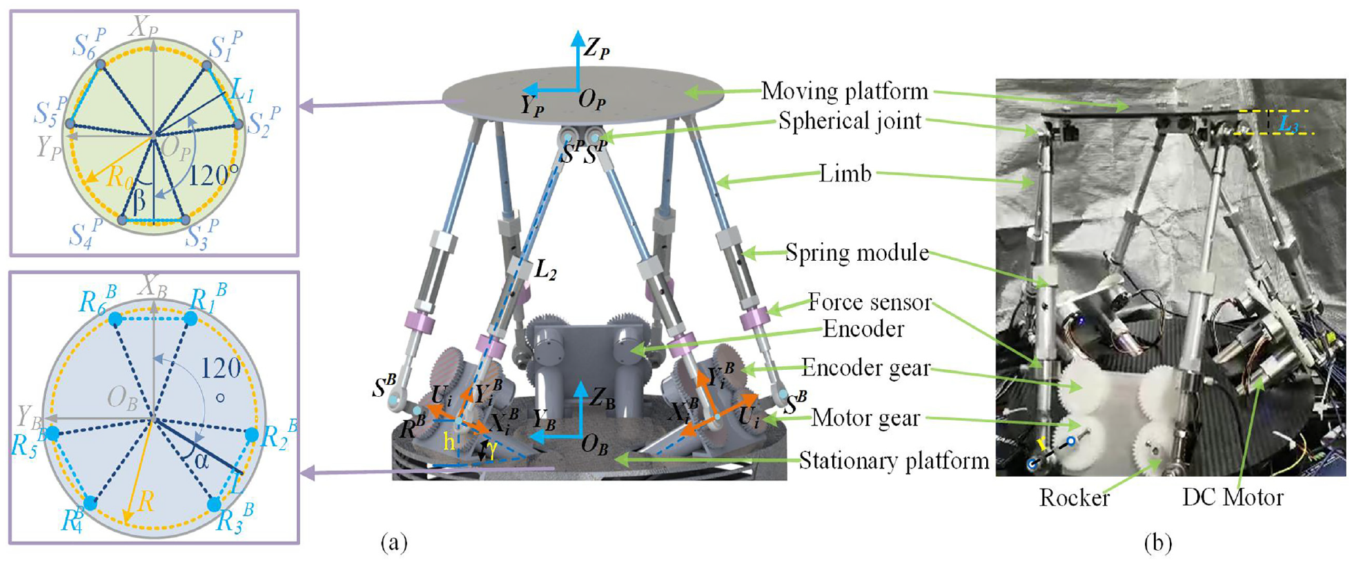
6-DOF-compliant bionic parallel mechanism: (a) 3D model and geometric configuration and (b) physical model.
The inverse kinematics of the 6-RSS parallel mechanism is solved for the joint angles (θi) of the six motors’ outputs from the known position and orientation [X, Y, Z, φ, θ, ψ] of the moving platform. In this parallel mechanism, the six motors are divided into three groups (1-6, 2-3, 4-5). The coordinate systems {B} and {P} are attached to the stationary and moving platforms, respectively.
The structure parameters.
The vectors
where ωi is the angle between
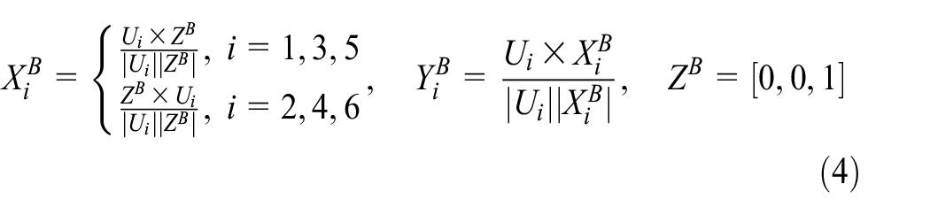
where C is the position vector of OP in {B}. The direction vector of the axis of the motor output shaft with respect to {B} is given by
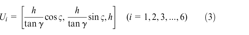
where ς = {0, −2π/3, −2π/3, −4π/3, −4π/3, 0} and corresponds to the orientation of each group of motors. The new reference system is established at the center point of the rotary joint at the output of the motor, with the direction vector of each axis defined as
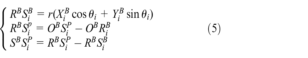
Then, the vectors on each limb are obtained
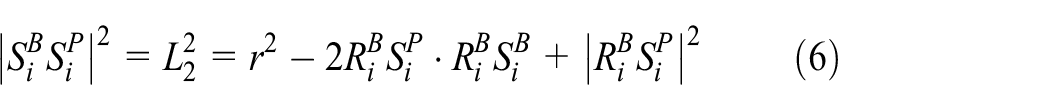
The distance between
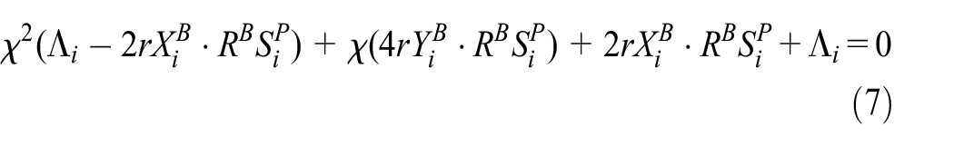
Thus, equation (7) is solved, and θi is equal to 2arctanχ. Based on this result, two solutions are possible. Then, the formula for the inverse kinematics is summarized as

The position of the drive motor on the static platform remains the same regardless of the change in the position of the moving platform. In contrast to the non-spring-loaded parallel mechanism, the length of each limb also changes when the flexible parallel mechanism is subjected to an external load. The rocker, motor, and stationary platform are considered as one unit in this paper. The length of the connecting limb with the spring module is defined as L2i. The variation of the length of the connecting limb ΔLT = [ΔL21, ΔL22, ΔL23, ΔL24, ΔL25, ΔL26] is known, and the variation in the position of the moving platform ΔPT =[ΔX, ΔY, ΔZ, Δφ, Δθ, Δψ] is required.
The unit vector of the connecting rod can be calculated based on
The velocity of the point

where
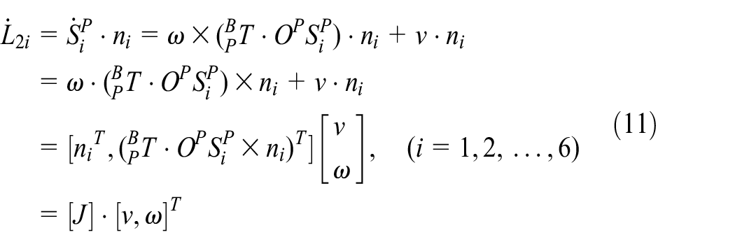
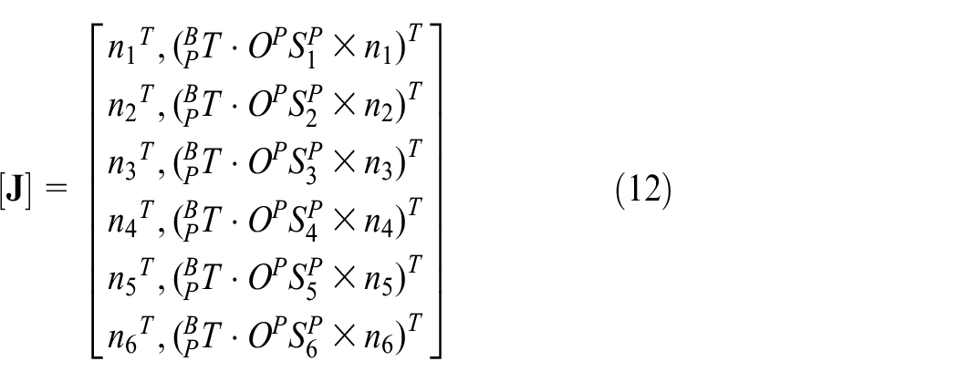
The rate of the variation of each limb length is finally abbreviated as equation (11). [

After obtaining the position and orientation variation of the compliant parallel mechanism platform, the motor angles can be solved by equation (8).
Kinetics
The 6-DOF parallel mechanism is a highly coupled complex nonlinear system. To facilitate the modeling solution, the model is simplified for its qualitative analysis. Each connecting rod is simplified as a spring-mass-damping system (Figure 2). Since the damping coefficient and mass distribution of the system are unknown, the dynamic characteristics of the mechanism are qualitatively analyzed. In this section, the dynamic of a flexible linkage is explored by analyzing the change in length of the linkage with time in a parallel mechanism under the force. The length of the flexible linkage is

where L2 is the original length of the limb of the parallel mechanism and xi is the deformation of the limb under the force. The differential equation of the system can be written according to Newton’s second law

where m is the mass of the block above the spring, c and k denote the damping coefficient and the stiffness coefficient of the spring, x is the displacement, and F is the input force to the system. m = 1, c = 5. The system transfer function is expressed as
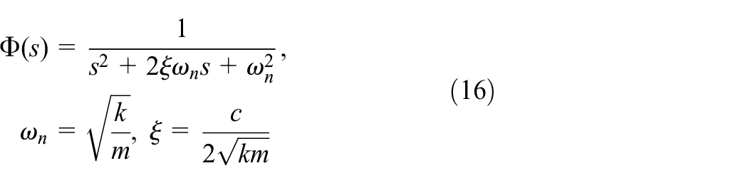
where ωn is the intrinsic frequency and ζ is the damping ratio. The Laplace transform of the system output at unit step response is
After the Laplace inverse transformation of the above equation, the unit step response of the system is finally formulated as
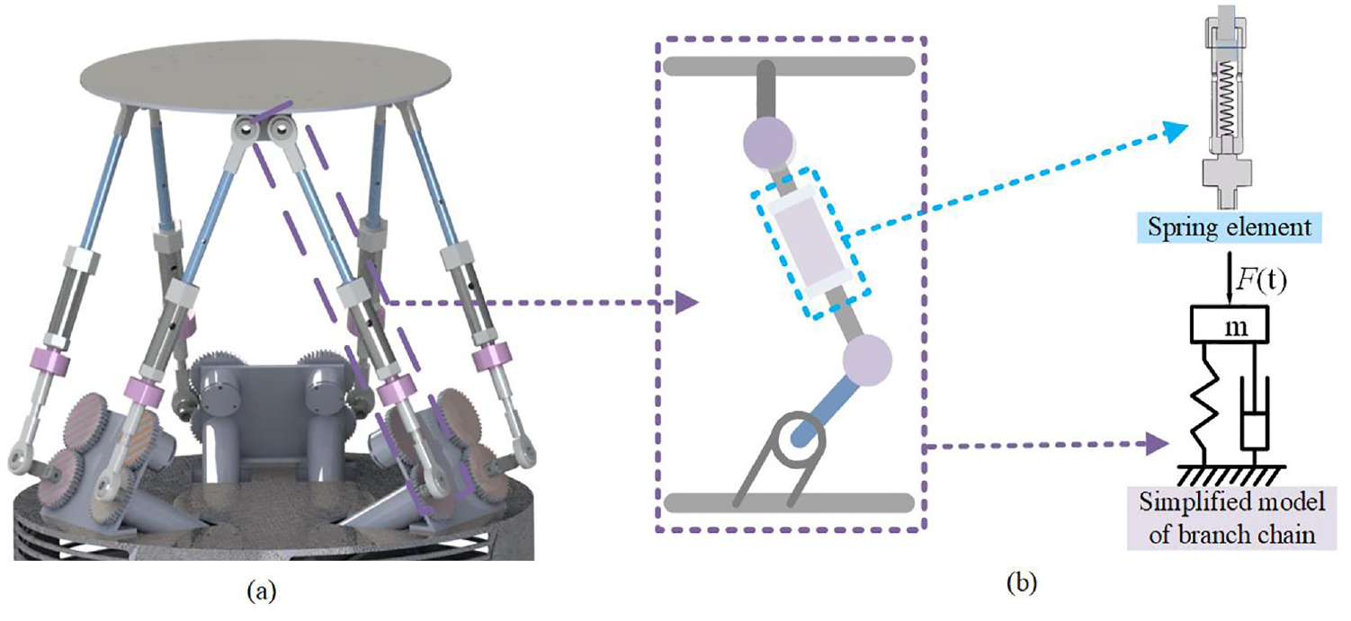
(a) 3D model compliant parallel mechanism and (b) single branch chain sketch.
Materials and methods
Characteristics of compliant elements
Cushioning force
To quantitatively measure the cushioning effect of the compliant parallel system, the maximum force applied to the system under the function of the unit step signal is chosen. Since the spring is in series with the limb, the maximum force on the link is the maximum force on the spring. The spring is subjected to the highest force at the time of maximum deformation without exceeding the elastic limit during the movement of the compliant parallel mechanism, and the corresponding moment is the peak moment tp. That is, the force at the peak instant is the system’s maximum force.
To obtain the peak moment, the unit step response of the system (equation (18)) is differentiated as
This equation is a periodic function. The spring deformation is maximum at the peak of each cycle. The peak moment in the first cycle, for example, is
At this peak moment, the response is
The maximum force on the mechanism is
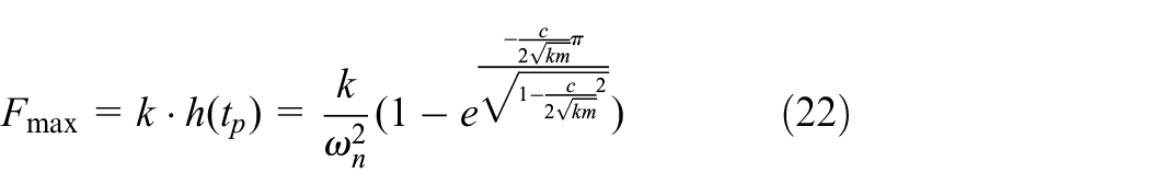
Figure 3(a) depicts the relationship between the maximum cushioning force on the system and the spring stiffness coefficients. The maximum cushioning force on the system increases as the stiffness coefficient increases. When the stiffness factor exceeds 4000 N/m, the maximum force does not change much.
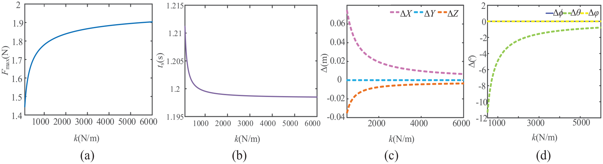
Characteristic diagram when spring stiffness is different: (a) cushioning force, (b) setting time, (c) position error, and (d) orientation error.
Setting time
The parallel mechanism with 6-DOF is proposed as a bionic torso. The parallel mechanism must have high dynamic properties to obtain improved motion performance. The setting time is a crucial criterion for the dynamic performance of the control system since it indicates the system’s response speed. Setting time refers to the shortest time it takes a response to reach a range of 5% (2% of the new steady-state value) and no longer be out of range. The setting time of the system is given as
The setting time of the system differs when the spring stiffness coefficient is different. Figure 3(b) depicts the system setting time characteristics. For spring stiffnesses less than 1000 N/m, the setting time of the system accelerates with the increase in the stiffness coefficient and the decrease rate becomes smaller. The setting time tends to a definite value after the stiffness coefficient exceeds 3000 N/m.
Positional accuracy
The irregular length change of each linkage impacts the position accuracy of a compliant parallel mechanism when it is subjected to stresses of the same size and in various directions. The initial position of the parallel mechanism is X = 0 m, Y = 0 m, Z = 0.26 m, φ = 0°, ψ = 0°, θ = 0°, and the spring stiffness is k = 1000 N/m. The forces along the X, Y, and Z axes and the moments around the X, Y, and Z axes are applied to the parallel mechanism individually, with the axial force being 200 N and the moment being 10 N m. The force along the axial direction of each link is obtained from the static solution (Zhu et al., 2021) of the parallel mechanism. The variation of the link length is calculated by Hooke’s law. The length variation of each limb under the load in different directions is displayed in Figure 4.
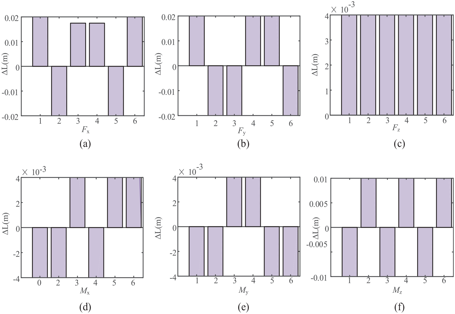
Length variation of six links under the action of different forms of external forces: (a) Fx = 200 N, (b) Fy = 200 N, (c) Fz = 200 N,(d) Mx = 10 N m, (e) My = 10 N m, and (f) Mz = 10 N m.
The limb of the parallel mechanism is separated into three groups (1-6, 2-5, and 3-4). In Figure 4(b)–(d) and (f), the deformation of each group of limbs is of the same magnitude and the forces are in opposite directions. The magnitude of deformation and the direction of force is the same for each group of limbs in both cases illustrated in Figure 4(a) and (e). The forces acting on the six links are identical and the deformation is the same when the external force is along the Z-axis. Figure 4 illustrates that the deformation generated by links is maximum when the parallel mechanism is subjected to loads along the X-axis or Y-axis. Large deformation will cause severe damage to the mechanism, so the force in the X or Y directions should be kept as low as possible to extend the life of the compliant parallel mechanism.
This section explores the positional accuracy of the parallel mechanism, using the example of simultaneous forces in the x and y directions. The initial position of the moving platform is consistent with the above. Fx = 10 N, Fz = −50 N. Posture error, calculated from equation (13) of the compliant parallel mechanism, is utilized to reflect the posture accuracy of the mechanism. The relationship between spring stiffness and the effect of parallel mechanism positional error is depicted in Figure 3(c) and (d). Y, φ, and ψ are always constant and are not affected by the change in stiffness coefficient. The errors of X, Z, and θ decrease as the spring stiffness k increases. When the spring stiffness is greater than 4000 N/m, the error tends to be nearly 0. In general, the higher the spring stiffness, the more accurate the position is.
Taking into account the cushioning force, setting time and position, and orientation accuracy of the compliant system, the stiffness coefficient of six spring elements in the compliant parallel mechanism was finally determined to be 3000 N/m.
Hardware control system
The control system of the 6-DOF parallel mechanism has to be scalable and maintainable to provide high-performance control. This work builds a decentralized control system architecture (Seok et al., 2014a) (shown in Figure 5) that connects all decentralized drives and sensors to the control system platform. CompactRIO-9627 Single-Board as a parallel mechanism controller mainly integrated with NI Linux real-time operating system, ARM Cortex-A9 processor, and Xilinx FPGA. The FPGA layer has several IOs that are programmed as communication ports. Each motor driver, encoder, and sensor in the system can be connected to the FPGA via these specialized communication connections. All input data is supplied synchronously and serialized to the multi-core processor for precise control performance. The data are again returned to the FPGA layer after processing. Eventually, the data are transferred in parallel and simultaneously to each decentralized device. The multi-core processor has two CPUs. CPU1 executes the control algorithm to generate the motion commands that drive the motor and record all of the data. The LabVIEW Real-Time module is used to program the processor to process the data streams in parallel, which allows for faster programming and greater operational efficiency. The CPU2, based on the data stream, is only utilized to operate the FPGA’s transceiver stream.
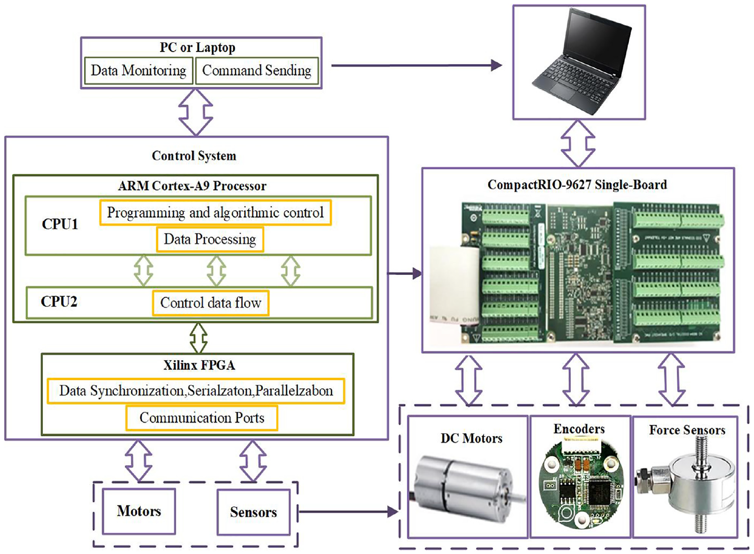
Hardware control system. The overall system has four layers, which are a PC, a multi-core processor, FPGA, and motors and sensors.
A PC or a laptop is used for data monitoring. The operator calculates the position information of the moving platform in multiple motion modes of the parallel mechanism in the user interface and then the joint angle is obtained. The operation command is transmitted to the control system with low latency.
The sensors dispersed throughout the system are joint angle encoders and force sensors. Embedded multi-turn absolute encoders are used for initializing the position of the parallel mechanism and for acquiring real-time motor position information. Since the encoder receives pulsed and non-uniformly leveled signals from the FPGA module, a PLC electro-optically coupled isolated differential signal conversion module is incorporated as an intermediate module between the encoder and the FPGA. Using this converter module, the RS422 differential signal from the encoder can be converted into a single-ended signal and sent to the digital port on the FPGA module for reading. Because the voltage at which the force sensor sends force information is too low to be gathered, a pressure transmitter is employed to transform it into a voltage range of ±10 V. The force information for the limb is derived by scaling the voltage signal.
Faulhaber brushless DC motors are used to drive parallel mechanisms with their lightweight, high torque, high power, smooth control, and good dynamic performance. At the same time, the FAULHABER MC5010 motion controller is chosen as the motor driver. The brushless motor and the driver work together to execute the high-level commands to drive the parallel mechanism movement.
Control framework
The control framework of the bionic parallel mechanism is presented in Figure 6. The rhythmic signals of the parallel mechanism branch chain are generated by a neuromechanical control network formed by coupling six σ-Hopf nonlinear oscillators (Zhu et al., 2019). The trajectory of the mechanism during motion in position is planned to simulate the behavior of a quadrupedal mammal (Zhu et al., 2021). By inverse kinematic calculation, the ideal joint angle of each motor is obtained from the position information corresponding to the trajectory. The desired motor angle is sent to the driver to actuate the motor and thus bring the parallel mechanism to the preset posture.
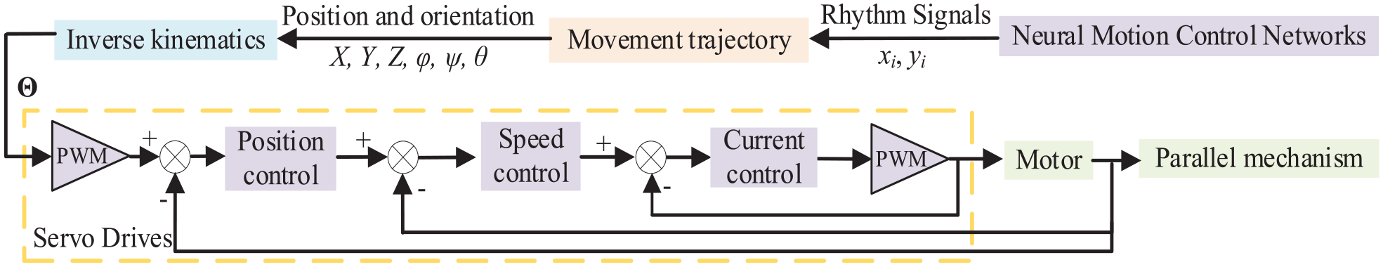
Control framework of flexible bionic parallel mechanism.
A position control method based on neuromechanical control is proposed to control the parallel mechanism. Cascade control with a combination of a primary controller and a secondary controller (for the motor) is applied in the practical work of the parallel mechanism. The PWM (pulse width modulation) technology is also adopted. The primary controller is in charge of generating the angle information driving the motor and converting the analog signal into a PWM signal. To achieve precise positional control, the secondary controller, the servo drive, regulates the motor angle using three closed-loop negative feedback proportional–integral–derivative (PID) controllers. These three closed loops are the position loop, speed loop, and current loop. Among them, position control is controlled by a pulse signal, while speed control and current control are controlled by an analog signal. The voltage output from the servo driver is sent to the motor in the form of a sinusoidal PWM signal for precise control of the motor angle.
Performance analysis
Dynamic response
We execute a dynamic simulation of the compliant parallel mechanism model in the Adams virtual environment to examine the dynamic properties of the multidimensional damping of the compliant mechanism. The simulation is conducted in three groups, with different instantaneous forces (FX = 50 N, FY = 50 N, and FZ = −100 N) applied to the moving platform in each group. The simulation lasts 0.3 seconds, and the impulse force lasts 0.01 seconds. Each set of simulations is run five times, with each spring in the limb having the same stiffness and damping coefficient. The spring stiffness coefficients are 500, 1000, 2000, 3000, and 5000 N/m for the five simulations, while the damping coefficient is always 0.05 N s/cm. Each motor angle starts at 0°. The displacement response and acceleration response of the compliant parallel mechanism to different directions of impulse forces under various stiffness settings are recorded in Figure 7.
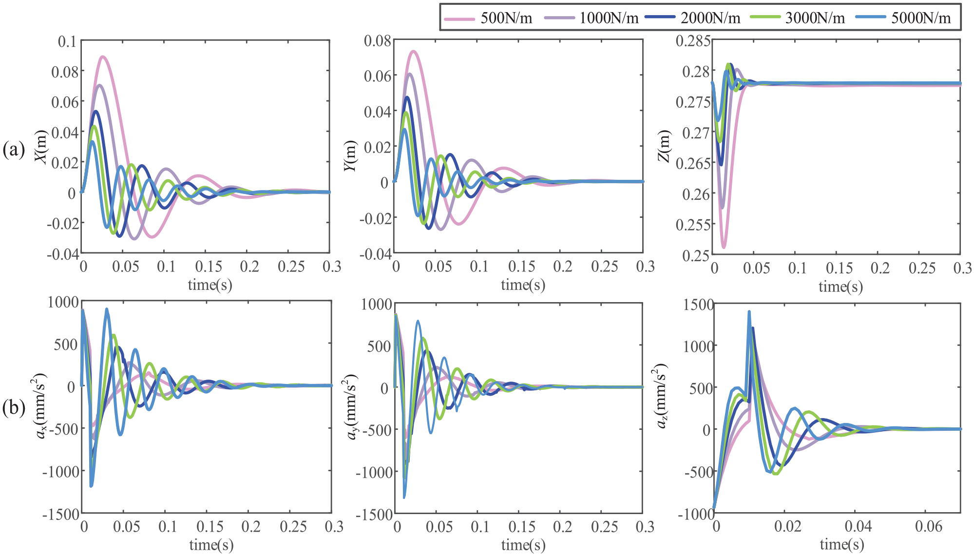
Dynamic response of flexible parallel mechanism: (a) the displacement response and (b) the acceleration response.
The displacement and acceleration responses of a moving platform subjected to transitory impulse forces in diverse directions would oscillate and drop and approach steady-state equilibrium in a short time, regardless of the stiffness of the spring element (Figure 7). It supports the theory that the compliant parallel mechanism exhibits multi-dimensional damping and buffering properties. The vibration peak and setting time of all displacement responses (Figure 7(a)) decrease as the stiffness coefficient increases. The displacement response of the dynamic platform in the X and Y directions is roughly 7 cm when the stiffness factor is 500 N/m. The peak displacement response reduces to 3 cm and the adjustment time is accelerated by 0.05 seconds when the stiffness factor is 5000 N/m. The displacement response time of the moving platform along the Z-axis is generally faster, at 0.05 seconds for 500 N/m stiffness and 0.03 seconds for 5000 N/m stiffness. The dynamic response of the compliant parallel mechanism shows that when the spring stiffness is greater, the setting time is shorter, while the cushioning effect is better when the stiffness factor is lower. Furthermore, as shown in Figure 7(b), an increase in spring stiffness leads to a growth in acceleration. This phenomenon causes the mechanism’s vibration to increase, resulting in greater impact forces. It indicates including spring elements of appropriate stiffness is obligated for the compliant parallel mechanism to have a decent cushioning effect.
Amplitude–frequency characteristics
The resonance needs to be eliminated for the compliant parallel mechanism to achieve better damping and cushioning effects. For this reason, we must identify the relationship between the machine parameters and the resonance frequency and determine the resonance frequency of the mechanism. In this way, the resonance frequency may be regulated and evaded as much as possible in practical applications, allowing the mechanism to vibrate with a lesser amplitude and thereby achieve the vibration reduction goal. This section explores the amplitude–frequency response characteristics of the compliant parallel mechanism.
The dynamic response in section “Dynamic response” is converted from the time domain to the frequency domain by the Fourier transform to analyze the vibration and amplitude–frequency characteristics of the compliant parallel mechanism. Here, the amplitude–frequency response in the X and Y directions is analyzed. Figure 8 indicates that the smaller the spring stiffness, the higher the amplitude of the response of the compliant mechanism. The resonant frequency rises as the stiffness coefficient rises, while the amplitude of the vibration falls. Smaller stiffness values are not conducive to the vibration damping of the system.
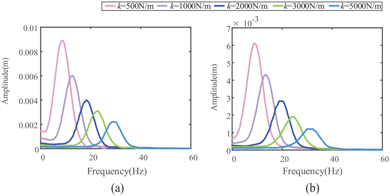
Amplitude–frequency characteristics of compliant parallel mechanism: (a) x direction and (b) y direction.
Variable stiffness characteristics
The compliant parallel mechanism is characterized by multiple DOFs. The compliant parallel mechanism with determined spring stiffness may exhibit similar cushioning and damping effects with different stiffnesses by sequentially changing the initial value of single information in position and orientation. The spring stiffness in this simulation model is 3000 N/m. The external force is 100 N, and its direction is 30° in the X, Y, and Z directions. The simulation duration is 0.3 seconds, and the external force lasts 0.01 seconds. The independent variable of this simulation is the initial position and orientation of the dynamic platform, and the dependent variable is the displacement response.
Initial position change
The dynamic cushioning performance of the system is examined by altering only the initial values of individual positions, while other positional information is left constant. The original poses of the parallel mechanism are X = 0 m, Y = 0 m, Z = 0.26 m, φ = 0°, ψ = 0°, and θ = 0°. The values of the initial variables of the spatial position of the parallel mechanism in different directions are indicated in Figure 9.
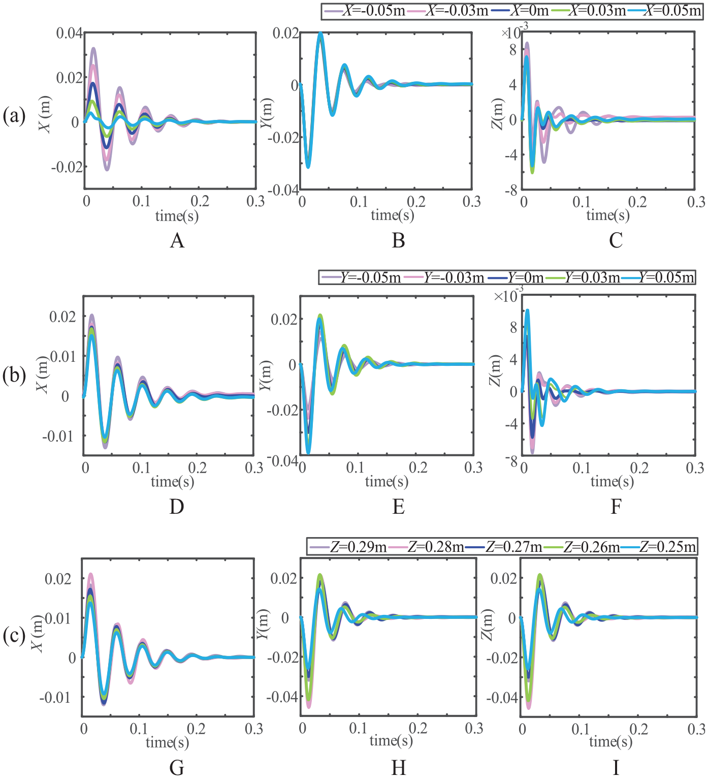
Dynamic response of the parallel mechanism during the initial position change: (a) initial value of X changes, (b) initial value of Y changes, and (c) initial value of Z changes.
As the initial value of X in the moving platform position varies from small to large, the amplitude of the dynamic response of the mechanism in the X and Z directions decreases consecutively. Changing the initial value of X does not affect the dynamic response in the Y direction or the response period in either direction. Regardless of the initial value of position Y, the response period in all three directions remains the same. However, as the initial value of Y increases, the vibration amplitude in the X direction decreases slightly, and the vibration amplitude in the Y and Z directions increases. The influence of the initial value of Z on the dynamic response in different directions is not evident. As shown in Figure 9(a) and (b), changing the initial position of the moving platform contributes to adjusting the cushioning damping characteristics of the parallel mechanism.
Initial posture change
Through simulations, we explored the effects of the initial orientation on the dynamic response of the mechanism. The simulation should ensure that the original position of the moving platform does not change. The simulation results in Figure 10 show that the dynamic response of the parallel mechanism subjected to forces is more apparent in the X and Y directions than in the Z direction. The amplitude of the response of the dynamic platform in the X direction is smaller when the initial values of the three posture angles are smaller, and this phenomenon is consistent with the effect of the system response when the spring stiffness becomes larger. An increase in the initial values of posture angle ψ and θ enlarges the vibration amplitude of the moving stage in the Y-direction. The greater amplitude shortens the service life of the mechanism. The increase in the initial φ value causes the reduction in the amplitude of the moving platform in the Y-direction to be beneficial to the mechanism. Although the effect of the dynamic response of the moving platform in the Z-direction is relatively small, the increase in the initial values of the different posture angles has a certain effect on reducing the amplitude of the response in all three directions. In addition, the change in the initial posture slightly adjusts the period of the dynamic response of the parallel mechanism.
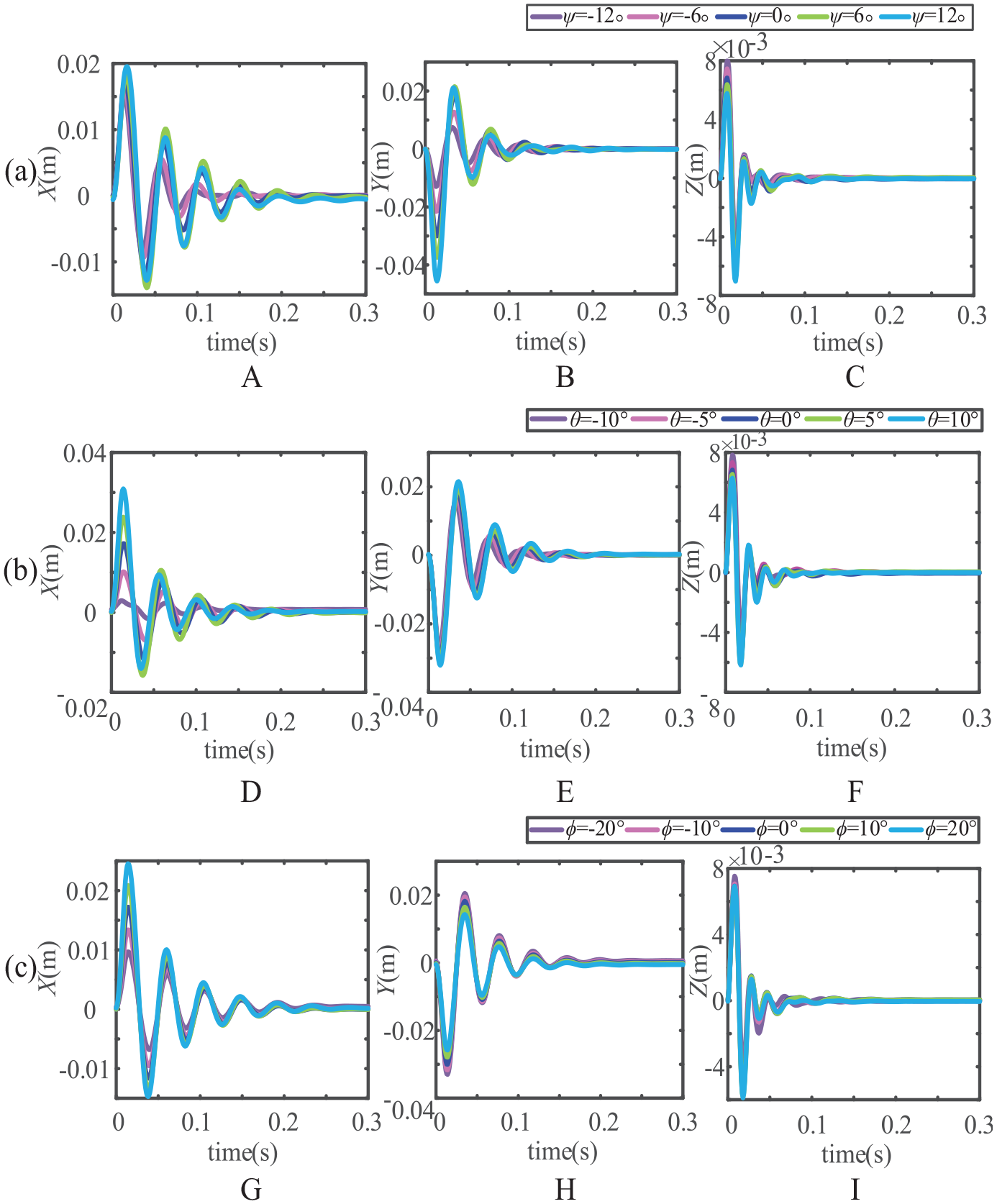
Dynamic response of the parallel mechanism during the initial orientation change: (a) initial value of ψ changes, (b) initial value of θ changes, and (c) initial value of φ changes.
In summary, the change in the initial position and orientation of the moving platform affects the vibration characteristics of the dynamic response of the compliant system. By adjusting the initial position and orientation of the moving platform, the dynamic response of the parallel mechanism can attain the desired vibration amplitude and period. The simulation results demonstrated that the variation of initial position helps the compliant parallel mechanism achieve similar vibration performance to that obtained by changing the stiffness coefficient.
Experiment
Rapid response experiment
The experiments first test the dynamic response of the compliant parallel mechanism in translational and rotational motion to verify the rapidity of the response.
Translational response
The initial positions and orientation of the moving platform are [0 m, 0 m, 0.26 m, 0°, 0°, 0°], [0 m, 0 m, 0.26 m, 0°, 0°, 0°], and [0 m, 0 m, 0.25 m, 0°, 0°, 0°], respectively, when the parallel mechanism is to make the translational motion in X, Y, and Z directions in the coordinate system {O}. [0 m, 0 m, 0.26 m] is the center of the reachable range of the parallel mechanism in the three-dimensional space. Since the movement range of the parallel mechanism along the Z direction is smaller than that of the X and Y directions, the Z value of the initial position is taken as 0.25 to have a significant movement effect of the parallel mechanism along the Z direction. The objective position of the parallel mechanism translating along three directions is an arbitrary position obtained by moving the moving platform in the coordinate system {O} along three axes. Figure 11(a) shows how the compliant parallel mechanism responds to translational motion in different directions. Three displacement responses in Figure 11(a) reach steady-state rapidly and without overshooting. The rise time (90%) is 0.12 seconds and the adjustment time (±5%) is 0.14 seconds for the response of the moving platform in the X-direction. The displacement response to moving the mechanism in the Y and Z directions has the same rise and adjustment times, 0.1 and 0.01 seconds, respectively. The displacement response of the parallel mechanism also has some steady-state error due to inaccurate gear set readings and approximate estimates of the kinematic solution. However, the steady-state errors when the moving platform moves in a translational motion are minor, and the larger one is only 0.0016 m.
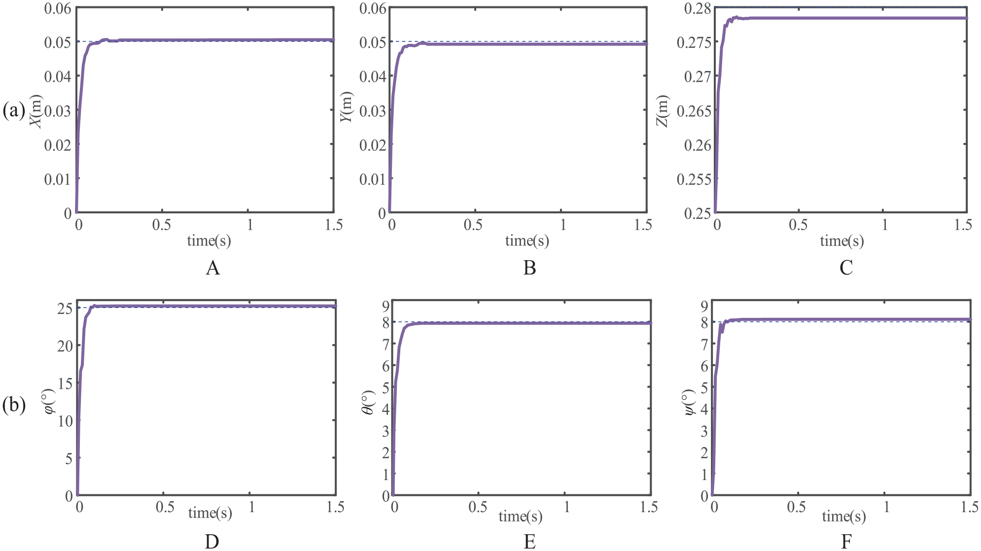
Dynamic response of the parallel mechanism: (a) translational response and (b) rotational response.
Rotational response
If the parallel mechanism is to rotate around the X, Y, and Z axes in the coordinate system {O}, the initial position and orientation of the moving platform is [0 m, 0 m, 0.26 m, 0°, 0°, 0°]. The objective positions and orientation of the parallel mechanism after rotating are [0 m, 0 m, 0.26 m, 0°, 0°, 8°], [0 m, 0 m, 0.26 m, 0°, 8°, 0°], and [0 m, 0 m, 0.26 m, 25°, 0°, 0°].
The parallel mechanism’s rotational response can quickly reach a steady state without a noticeable overshoot, as shown in Figure 11(b). The setting time corresponding to the response of translational motion in the same rotation direction as φ and ψ is within 0.1 seconds. When the direction of rotation is the same as θ, the rise time (90%) is 0.14 seconds and the setting time (±5%) is 0.16 seconds. The parallel mechanism is experimentally verified to reach a steady state quickly for both the translational and rotational responses.
Vibration damping
The dynamic response of the compliant parallel mechanism under external forces is used to analyze the vibration damping performance. Place mass on the moving platform instead of applying force in the Z direction. The initial position is [0 m, 0 m, 0.268 m, 0°, 0°, 0°], FZ=−20 N, and the spring stiffness coefficient k=3500 N/m. During the motion of the parallel mechanism, the force sensor in each branch chain measured the force on each link. Then, the length variation of each limb is obtained according to Hooke’s law. The dynamic response of the dynamic platform position under the force is derived from the solution of the inverse kinematics of the compliant parallel mechanism.
When the force on the moving platform in the Z-direction changes, the displacement response of the parallel mechanism in all three directions (Figure 12) is oscillating and gradually converges to a determined value. The amplitude of the displacement response decreases sequentially and vibrates within the error tolerance after 1 second to reach steady-state equilibrium. The effective decay of the step response in the three directions confirms the multidimensional cushioning and damping characteristics of the compliant parallel mechanism.
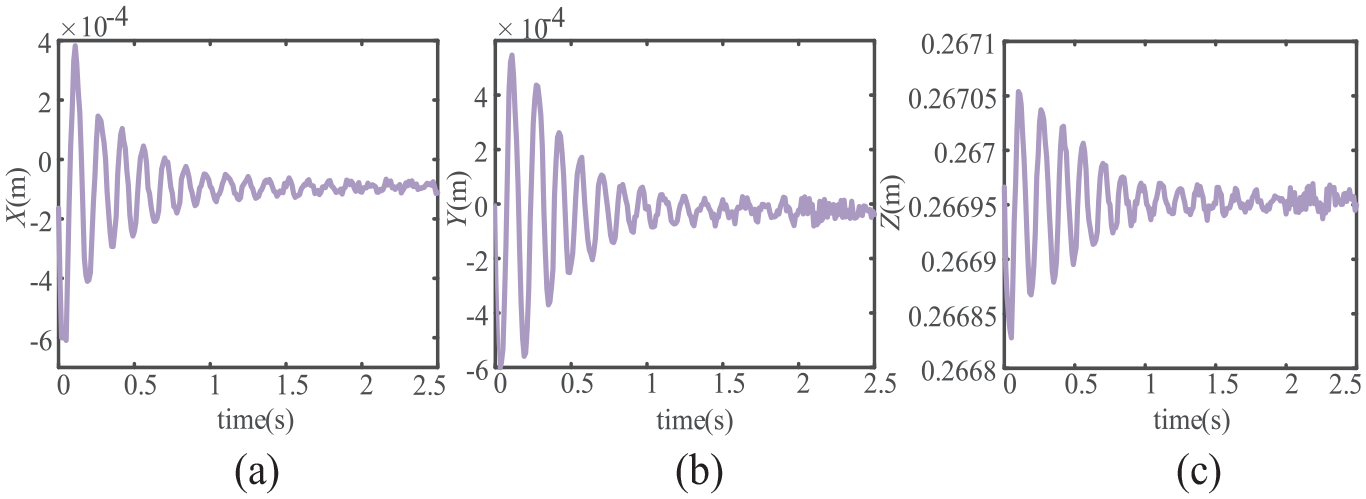
Displacement response of compliant parallel mechanism under force: (a) X direction, (b) Y direction, and (c) Z direction.
Motion experiment
Independent locomotion
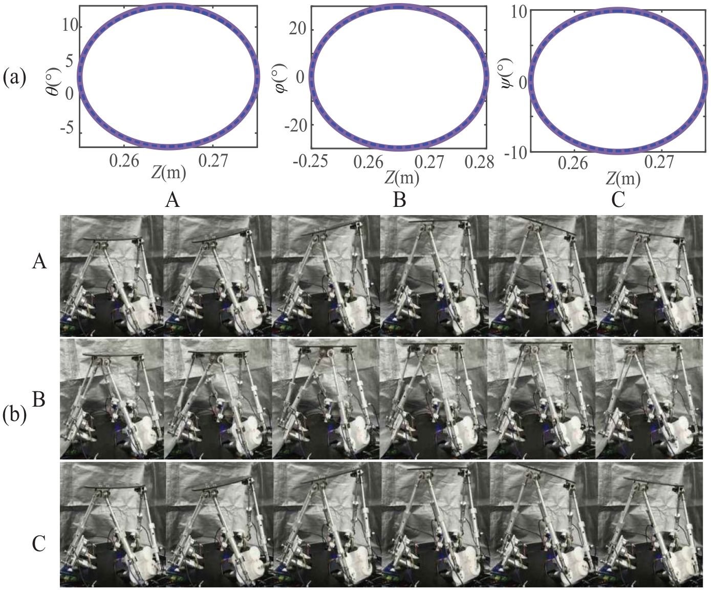
This 6-RSS-compliant parallel mechanism enables independent and coupled motions of three movements and three rotations in the Cartesian coordinate system. We first test the independent motion of the parallel mechanism. The trajectories of the single-DOF motions are sequentially planned as X = 0.05sin(πt), Y = 0.06sin(πt), Z=0.265 + 0.02sin(πt), θ = 5+12sin(πt), φ = 25sin (πt), and ψ = 8sin(πt). The control frame in section “Control framework” is used to drive the parallel mechanism to move according to the planned trajectory. Each single-DOF motion lasts 10 seconds. The process of the single-DOF motion of the compliant parallel mechanism is recorded in Figures 13 and 14.
Translational experiment. (a): (A) Desired displacement trajectory and actual displacement trajectory, and (B) trajectory error. (b): Translation process of flexible parallel mechanism: (A) move along the X-axis, (B) move along the Y-axis, and (C) move along the Z-axis.
Rotation experiment. (a): (A) Desired orientation trajectory and actual orientation trajectory and (B) trajectory error in X, Y, Z directions. (b): Rotation process of flexible parallel mechanism: (A) rotate around the X-axis, (B) rotate around the Y-axis, and (C) rotate around the Z-axis.
The trajectory of the moving platform along the three axes of the Cartesian coordinate system followed the pre-planned motion trajectory well. The position error is small, within the range of ±0.003 m. In translational motion, the position error varies sinusoidally and increases with the increase in displacement. The position error is the smallest when moving along the Z direction and the largest when moving along the X-direction. The rotation of the moving platform around the three axes in the Cartesian coordinate system achieved a better position-tracking effect. The error also varies sinusoidally and increases with the increase in the rotation angle, and the maximum error reaches ±0.5°. Comparatively speaking, the rotation error around the Z-axis is the largest, and the rotation error around the Y-axis is the smallest.
Consequently, the parallel mechanism has minor position errors in all six simple motion modes. The errors are likely caused by the clearance between the gear sets and the poor accuracy of the forward kinematics approximation solution. However, the difference between the actual and theoretical trajectory is small and acceptable.
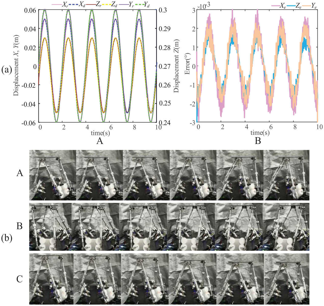
Coupled locomotion
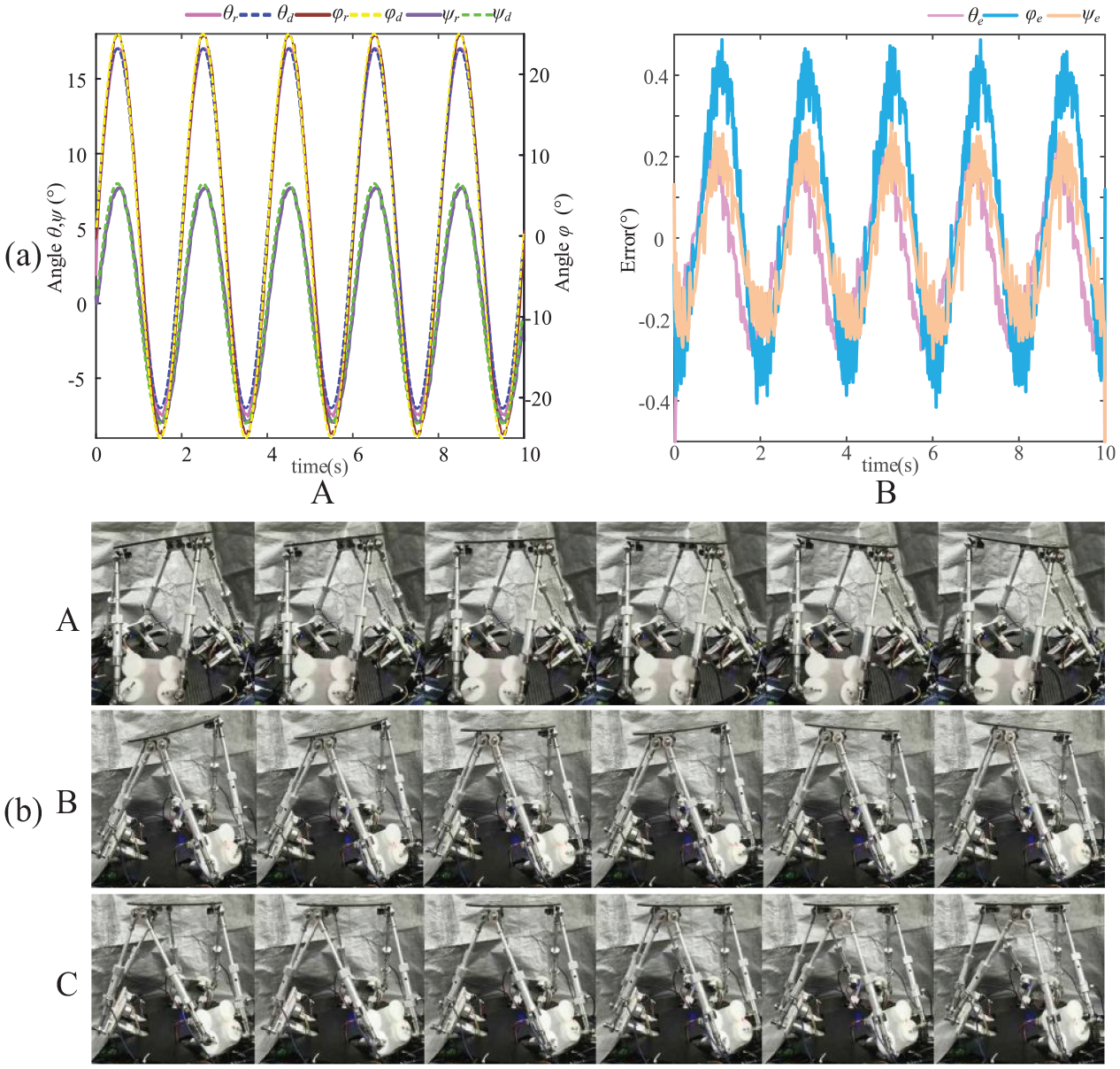
Coupled motions imitating the stretch and bend, twist, and lateral rotation of the tetrapod torso were tested for the compliant parallel torso. The motion trajectories of the parallel mechanism were planned individually for the three coupled motions. During the extension and flexion of the compliant mechanism (Figure 15(b(A))), the moving platform rotates around the Y-axis with θ = 3 + 10sin(πt) while moving along the Z direction with Z = 0.265 + 0.01cos(πt). The torsional motion (Figure 15(b(B))) is realized when the moving platform rotates around the Z-axis with φ = 30sin(πt) and moves along the Z direction with Z = 0.265 + 0.015cos(πt) at the same time. The motion of the parallel mechanism side rotation (Figure 15b(C))) is planned to rotate around the X-axis with ψ =10sin(πt) while moving along the Z direction with Z = 0.265 + 0.01cos(πt).
Coupled experiment. (a): Desired orientation trajectory and actual orientation trajectory in (A) θ, (B) φ, and (C) ψ. (b) Rotation process of compliant parallel mechanism.
The actual posture angle trajectory of the parallel mechanism in different motion modes follows the desired trajectory well and the error is within the acceptable range. The reasons for the errors are consistent with those described above. The experimental results of simple and coupled motions of the parallel mechanism show that the bionic parallel torso can effectively simulate the multimodal behavioral motions of the biological torso.
Conclusion
This paper proposed and developed a 6-DOF-compliant bionic parallel torso with elastic modules. The kinematics and dynamics of the parallel mechanism were analyzed in detail, and the control system and framework of the compliant system were constructed. The correlation between the stiffness coefficient of the spring element and Cushioning force, setting time, and positional accuracy of the compliant system was clarified. In addition, the variable stiffness characteristics of this compliant mechanism can meet the different stiffness requirements of the pedestrian robot under different gaits and speeds. The multidimensional damping and cushioning characteristics of the compliant parallel mechanism are verified experimentally and simulational by installing the spring elements with suitable stiffness coefficients into the branch chain of the parallel mechanism. The proposed active bionic parallel torso can also realize multimodal behavioral actions such as extension and flexion, twisting, and lateral rotation of the animal torso. This study will provide a new theoretical basis for the exploration of the compliant torso. The compliant parallel mechanism developed presently will be applied to the development of quadrupedal robots. In the future, we will work on multimodal behavioral studies of quadruped robots with bionic parallel mechanisms.
Footnotes
Declaration of conflicting interests
The author(s) declared no potential conflicts of interest with respect to the research, authorship, and/or publication of this article.
Funding
The author(s) disclosed receipt of the following financial support for the research, authorship, and/or publication of this article: The work presented in this paper was supported by the Fundamental Research Funds for the Central Universities (Grant No. 300102259308), in part by the Scientific Innovation Practice Project of Postgraduates of Chang’an University (Grant 300103722027).