
Abstract
The load-bearing behavior and the performance of composites depends largely on the bond between the individual components. Conventional grid-like textile reinforcement structures with thin and smooth yarn structures transmit forces primarily by an adhesive bond with the surrounding matrix. A sufficient load transmission is not possible. Thick, pultruded rebars made of fiber-reinforced plastics can be profiled by subtractive (e.g. milling) or additive (e.g. wrapping) techniques in order to create a rip-like structure and increased shear bond. Yet the discontinuous fiber course results in material inefficiency. A newly developed profiling technique allows a tetrahedral profiling of the complete roving structure, yet considering its anisotropic properties. In the article, we present this approach, and the first results from single yarn tensile and pull-out tests of single, double and triple plied profiled rovings in concrete and asphalt matrix. Thus, the highest bond is achieved in the brittle concrete matrix. Plied rovings with strong tetrahedral profiles show up to 600% higher bond stress compared with rovings with circular profiles, while maintaining high tensile properties. However, splitting-induced failure of the reinforced test specimens occurs, making plied profiled rovings favorable for high concrete cover and less brittle matrixes; for example, asphalt. The reinforced asphalt specimens show at −10°C similar bond properties, but at 30°C the bond decreases by 80%. In summary, the study shows that bond properties of profiled rovings are superior to conventional circular rovings, and promise a high material efficiency for use in concrete and asphalt reinforcements.
Keywords
Concrete is the most important and most frequently used building material in the world. In almost all areas of application, the compression-resistant concrete is used in combination with reinforcement to absorb the tensile forces 1 However, only the combination of concrete with a reinforcement material; for example, steel, allows the erection of structures that can withstand the highest stresses. Due to the susceptibility of steel to corrosion, however, a significant cover layer (at least 6 cm) of the highly alkaline concrete is necessary to prevent premature loss of load-bearing capacity due to corrosion of the steel reinforcement. 2 As the additional thickness of the cover layer does not contribute to the transfer of the compressive loads acting in the structure, it results in a systematic, unnecessary oversizing. Taking into account the high carbon dioxide (CO2) emissions for the production of concrete, and in view of the efforts to achieve a climate-neutral, sustainable building industry, textile concrete reinforcements have been developed and successively introduced in practice in the past two decades. These nonmetallic reinforcements consist of high-performance multifilament yarns (also called rovings) based on corrosion-resistant carbon or basalt or alkali-resistant glass.3–5 The yarns are processed into multi-axial lattice structures using textile processes. To ensure the internal bond between the fibers in the yarn and a minimum external bond between the yarn and the surrounding concrete matrix, the lattice structures are usually impregnated.6–10 In contrast to metallic reinforcements, which are susceptible to corrosion, the above-mentioned fiber-based reinforcements are corrosion resistant, so that the covering layer previously required to retard corrosion can be dispensed with. Thus, the use of such textile concrete reinforcements can result in concrete savings of up to 70% (due to thin-walled construction), although the same forces can be transmitted as with conventional steel reinforcements.11,12 Therefore, they allow a very material-efficient, sustainable (concrete-saving) and durable reinforcement of concrete structures and components in a variety of applications.13,14 Thus, future trends and current studies emphasize the need for innovative textile reinforcement structures with adapted design, improved processing technology, and new construction methods in order to utilize fully the high performance potential of the textile material.15–18
Asphalt mastics
Asphalt is a mixture of bitumen, additives, filler and aggregates, with a continuous grading curve (0.063–22 mm grain size) 19 and reduced brittleness as well as high temperature dependent properties compared with concrete matrices.19–21 Asphalt pavements are constructed in layers for technical and functional reasons (see Figure 1(a)).
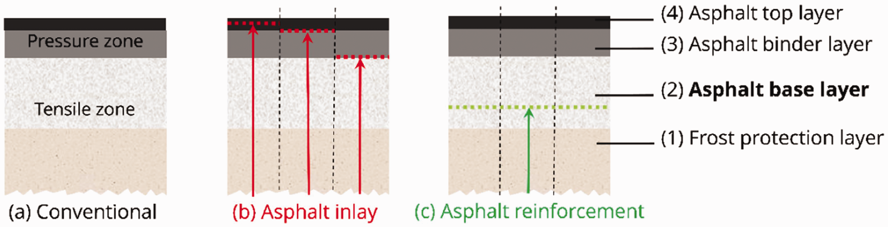
Schematic representation of a conventional asphalt pavement according to RStO 12, 22 without inlays of reinforcements: (a) with conventional asphalt inlays in the top and binder layer; and (b) the newly textile-based asphalt reinforcement in the asphalt base layer (c).
Conventional asphalt pavements are constructed without reinforcement. The installation of lightly loadable textile asphalt inlays is limited to rehabilitation measures in the upper surface layers (see Figure 1(b)).
Road pavements are subject to cyclical alternating loads due to the rolling of vehicle tyres. The empirical dimensioning according to RStO 12 22 assumes a service life of 30 years for the asphalt base layer, which is not achieved on heavily loaded stretches of road, and requires a thorough renewal after just 15–20 years.23,24 Thus, the temperature scenario and temperature dependency of the asphalt brittleness also influences the durability, whereas the deep lying asphalt base layer varies between −10°C and +30°C 25 during winter and summer.
In road construction, simple textile structures available on the market have so far been used to rehabilitate the asphalt surface and binder layer more durably and cost effectively. The so-called asphalt inlays made of polyester as well as glass and carbon fibers sustainably delay the formation of reflective cracks, and enable a reduction in layer thickness, although an improvement in the fatigue behavior of the entire asphalt pavement has not been proved.26,27
Paving is carried out between the existing, cracked asphalt base layer and binder layer, or the asphalt binder and top layer (see Figure 1(b)). Asphalt inlays are adapted to the low requirements (low tensile stresses) in the upper asphalt top layer with smaller grain sizes, and are therefore unsuitable for the reinforcement of the asphalt base layer with significantly higher demands on the reinforcement (very high tensile stresses). This requires rovings with high yarn count in order to utilize the high load-bearing capacity of the carbon fibers, with the initial bond forcing a minimal deformation of the asphalt base layer. Furthermore, the profiled rovings have to survive the paving of the asphalt base layer with increased grain size of up to 22 mm, and must therefore be highly robust.
Bond behavior of textile reinforcements in building matrices
The bonding mechanisms in textile reinforcements in concrete matrix for building applications have long been the subject of research.5,10,28–31 It was recognized early on that an effective and complete internal bond in the yarn is a prerequisite for efficient material utilization, because otherwise the core filaments inside the yarn participate significantly less or not at all in the load transfer.5,32 These findings are also based on the research of fiber reinforced plastics (FRPs). Yet, in contrast to FRPs, textile reinforced concrete allows initial crack formation of the brittle concrete matrix at a structural elongation of approximately 0.2% before complete load transmission to the textile reinforcement. 8 Common impregnations for rovings are now based on styrene-butadiene rubber, epoxy resin, venylester resin or polyacrylate (PA).10,33–35 All of them improve the internal bond compared with unimpregnated yarns, and increase the structural stability. 33
The bond of continuous fiber reinforcements in asphalt matrix for road pavement is a completely new research area, and therefore no data or information are available. First investigations will be part of this study.
Bond mechanisms
The external bond between the yarn and surrounding matrix; for example, concrete or asphalt, is mainly based on three mechanisms36–38 (see Figure 2(a)). Adhesion is caused by the ingrowth of hydration products into the impregnation layer and/or the yarn. 39 It is based on adhesion or chemical bonding between the impregnation layer and the cement paste. A relative displacement between the yarn and surrounding matrix overcomes the adhesion and activates the frictional bond, which depends primarily on the roughness in the interface between the yarn and matrix.32,37 Depending on the impregnation used, the bond can fail early (soft or ‘low modulus’ impregnations such as styrene-butadiene rubber) or continuously (stiff or ‘high modulus’ impregnations such as PA or epoxy resin) (see Figure 2(b)).10,28,40 The shear bond; for example, form fit (mechanical interlocking) can be influenced by geometric shaping, yarn processing, the periodic widening of the yarns between the crossing points in a fabric, the yarn waviness, or the cross yarns that are firmly attached to the stressed yarn.37,41–43
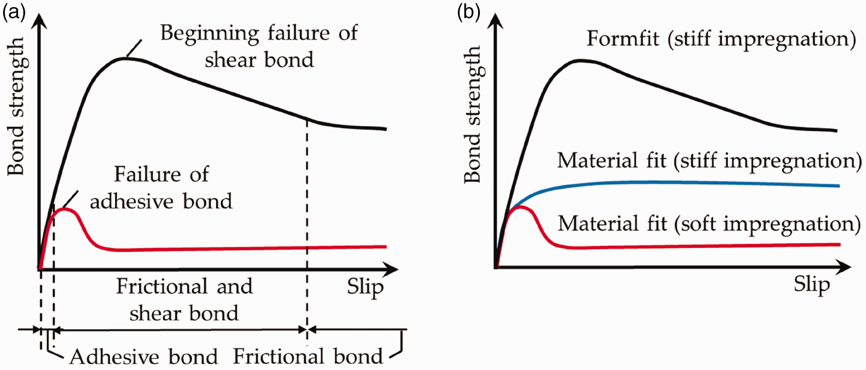
Schematic bond between textile reinforcement and concrete matrix in the dependence of the bond proportion (a) and the material properties (b).
The bond is characterized on the basis of bond flow-crack opening or derived bond stress-slip relationships.29,43,44 There are several types of composite tests for their determination. The single-sided pull-out test (SPO) is suitable for the investigation of very short anchorage lengths and the failure mechanism ‘splitting’. 45 In comparison, the double-sided pull-out test (DPO) allows longer anchorage lengths.6,29,36,37 Yarn force–anchorage length relationships are determined, and an approach to the final anchorage length is possible. The lap test 36 is universally suitable for determining lap lengths. Due to the prevailing stress state in the overlap zone, a slightly longer length is usually determined than for the final anchorage. Yarn pull-out (YPO) tests46,47 are suitable for thin specimens in which splitting of the specimen clearly influences the test results from SPO and DPO. Specimen preparation and handling are simpler than for DPO and SPO, which makes YPO suitable for continuous quality control and screening. Longer anchorage lengths can be investigated than with SPO. Any influence of transverse threads is not taken into account. An upper limit for the anchorage length that can be investigated results from the handling. End-anchorage tests are used to determine an end-anchorage length.
Different failure modes occur in the tests. In the case of a yarn break (without pull-out from the concrete), the yarn tensile force was completely transferred into the surrounding matrix. Neither the internal nor the external bond was failure-inducing, and the reinforcement was fully exploited. When yarn is pulled out of the matrix, the adhesion in the interface between the yarn and surrounding matrix is too low, and the bond length is insufficient for complete force transfer. Telescoping yarn pullout results from insufficient internal bond between core and edge filaments (failure due to uneven load transfer between filaments). In addition, the surrounding matrix may fail; especially in the case of the so-called newer generation textiles with higher yarn cross-sections and stiffer reinforcement, there is a risk of splitting of the specimen (longitudinal cracking and/or splitting of the concrete cover).29,32,36,37,41 The causes are often flat or oval yarn cross-sections due to the manufacturing process, and the periodically undulating reinforcement structure. This results in splitting tensile stresses orthogonal to the textile reinforcement, which favor splitting, especially in case of brittle concrete matrix with small corners. Reference is made to the well-known ring tensile model from reinforced concrete construction.31,42
Important factors influencing the bond (bond strength and bond stiffness) between textile and concrete, and thus also the crack formation, are the material characteristics of fiber, impregnation and concrete matrix, impregnation quantity, yarn and scrim geometry, textile weave and processing, the stiffness of the textile in its plane and the ambient temperature.10,36–38 Accordingly, the shape of composite flow-crack opening relationships is diverse with respect to the characteristics of the three composite components.
This study focuses on improving the bond behavior through profiling and increasing the shear bond (e.g. form fit). There are various known approaches to this.
This study focuses on the newly developed impregnation forming technology, in order to produce tetrahedral profiled rovings with continuous filament course. Thus, different profile characteristics and filament counts are investigated in order to evaluate their influence on tensile and bond properties, and identify preferable parameters for highest tensile and bond properties for use in concrete and asphalt structures.
Manufacturing technologies for the production of profiled reinforcement yarns
Processing of multifilament yarns
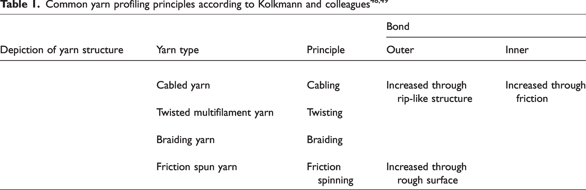
The known processes for generating a profiled yarn surface are cabling, twisting, conventional braiding or friction spinning.48,49 In these processes, a defined yarn geometry is realized by alternate insertion, interlacing or twisting of the individual yarns (presented in Table 1), which leads to an increase in the internal bond, and an improved concrete bond at the yarn surface (external bond). 49 However, the modification of the yarn structure necessary for profiling affects the material characteristics, especially the stiffness and strength properties, of the yarn. For effective use in concrete, this means that the reinforcing yarn must be capable of absorbing the tensile forces to be transferred already at elongations from about 0.1% to 0.2%. The disadvantage of the above-mentioned method is the comparatively high structural elongation of greater than 1% before complete load absorption, which can result in large concrete crack opening widths. 50
Pultrusion of FRP rebars
For larger reinforcement diameters (≥Ø8 mm), profiling processes allow profiling from a homogeneous yarn structure. Using polymeric matrix material and, if necessary, in combination with thermal processes, profiled fiber reinforced composites (FRPs) can be generated along the yarn axis (e.g. by embossing).51,52 Subtractive milling of rib-like structures into pultruded reinforcing bars or additive wrapping of a helical structure is also used (presented in Table 2). Details about the production processes of exemplary rebar structures (presented in Table 2) are given in Böhm et al. 52 and Schumann et al. 53
Principles for surface profiling of pultruded FRP rebars according to Schumann et al. 53
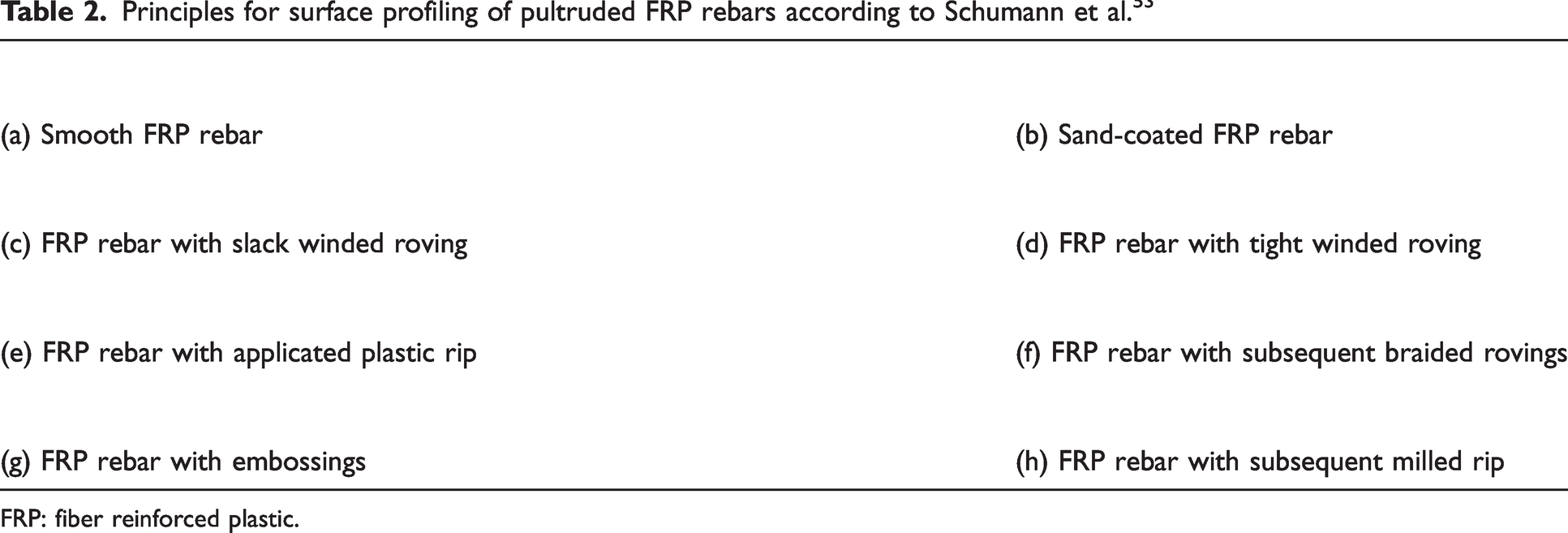
FRP: fiber reinforced plastic.
The application of coatings or anchoring structures such as adhesives, sand or plastic ribs (especially for bar-shaped reinforcement elements), as well as additive and subtractive profiling processes change the bond properties due to the additional positive locking effect.53–61 The decisive factors for the effectiveness of the positive locking are the durability and (composite) strength of the material bond between the yarn and the cover/anchoring,31,41 because there is no continuous fiber course in the outer profiling. When high bond forces are transmitted, this material bond usually fails prematurely due to shearing of the rib or helix-like structures, and the rebar is pulled out before the high-performance fibers are fully loaded.53,60 Special anchoring constructions can make handling more difficult. In addition, the subtractive and additive ones have an increased material input, which is contrary to the ecological and economic objectives, especially in view of the energy-intensive carbon fiber production. Consequently, the FRP bars exhibit reduced material efficiency, which results in over dimensioned reinforcement cross-sections.
Steel reinforcements
For steel reinforcements, a large number of geometric variations were investigated before the established, structural steel profiling BSt 500 S with longitudinal ribs was established as the globally recognized standard.62–65
In the case of isotropic reinforcing steel, the focus for several decades was on the interactions between geometry and surface properties, failure mechanisms (including splitting of the concrete), ductility, and fatigue strength. In the case of FRP reinforcement, the anisotropy of the reinforcement material and the specifics of the fine concretes are added. Therefore, new development approaches are required with regard to the yarn profiling process and the profile geometry, in which analogies of steel profiling (profile spacing, inclination and related effective areas) can be partially transferred.
Yarn profiling technology
For reinforcements with smaller yarn diameters, as they are required in flat components or in structural reinforcements in combination with low concrete layer thicknesses, the additive or subtractive processes mentioned are not suitable for generating a yarn profile.
In contrast, shaping by means of impregnation forming technology, which was developed at the Institute of Textile Machinery and High-Performance Material Technology (ITM) at the TU Dresden, is a promising approach for material-efficient yarn profiling that is also suitable for the material.66–68 This allows profiled yarns with predefined profile properties to be realized.
The impregnation forming process is characterized by the fact that dry yarns are first impregnated with an impregnating agent, then formed along the longitudinal axis of the yarn in the impregnated state, and finally consolidated in the formed state with the application of heat. A periodic change in cross-section along the longitudinal axis of the yarn is particularly advantageous (see Figure 3).
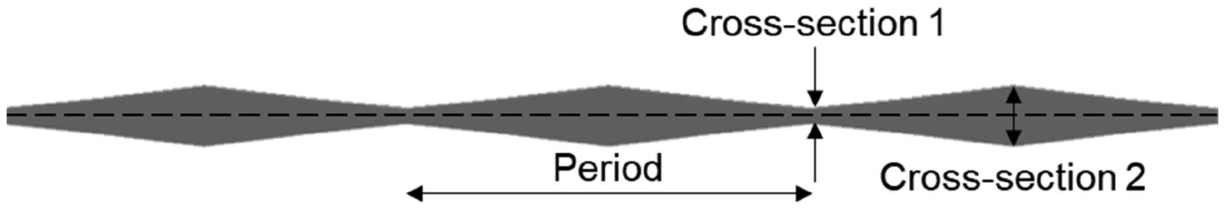
Profiled roving with periodic cross-sectional change along the longitudinal yarn axis.
In contrast to subsequent, subtractive or additive profiling methods, the impregnated, flexible, soft yarn state allows all filaments in the yarn cross-section to be rearranged in the course of the cross-section change, so that they are stretched between the cross-section changes despite the resulting filament deflection from the longitudinal yarn axis. Provided that the impregnation is stiff and the profile geometry is fully consolidated, the impregnation forming process with periodic cross-section changes enables powerful exploitation of the anisotropic, direction-dependent properties of the filaments.
Depending on the profile geometry, the high tensile mechanical properties of the anisotropic yarns can be largely retained despite profiling and fiber deflection, provided that the profiling process is uniform and gentle on the fibers, because the shaping is realized directly from the yarn structure with rearrangement of the filaments. For example, in the so-called tetrahedral geometry of the yarns shown in Figure 4 (hereafter also referred to as basic topology), the rearrangement of the filaments results in an almost uniform filament course between the cross-sectional changes, so that with complete consolidation on load application, all core and edge filaments participate almost equally in the load transfer. The anisotropic fiber properties are exploited very well, resulting in very high tensile strength and stiffness.66–68
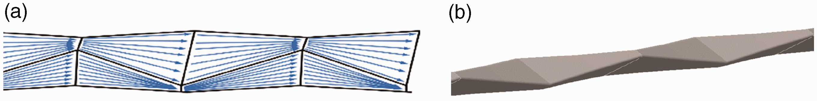
Schematic depiction of a tetrahedral profiled roving.
A detailed explanation of the profiling technology and machinery is given in Penzel and colleagues.66,67 Thus, single rovings with different profile configurations and process parameters (e.g. impregnation agent, consolidation parameters) were produced and investigated according to their influence on tensile and bond behavior. Thus, a strong tetrahedral profile in combination with a stiff impregnation (e.g. PA) and intensive consolidation (heating) results in highest tensile and bond properties, with more than 500% higher bond strength compared with single rovings with a circular profile.
Materials
Rovings with different configurations for carbon fiber reinforcement
The carbon fiber heavy tow Teijin Tenax-E STS 40 F13 48K (Teijin Carbon Europe GmbH, Germany) was selected to investigate the influence of profiling on the mechanical properties. All different single and plied rovings in this study were produced with this carbon fiber heavy tow. The properties of the dry yarn without impregnation are presented in Table 3. The tensile strength was determined in single yarn tensile tests at ITM, according to Wendler et al. 69 and ISO 3341 70 (see the sections on Asphalt mastics and Bond behavior of concrete embedded rovings, below).
Properties of the dry yarn
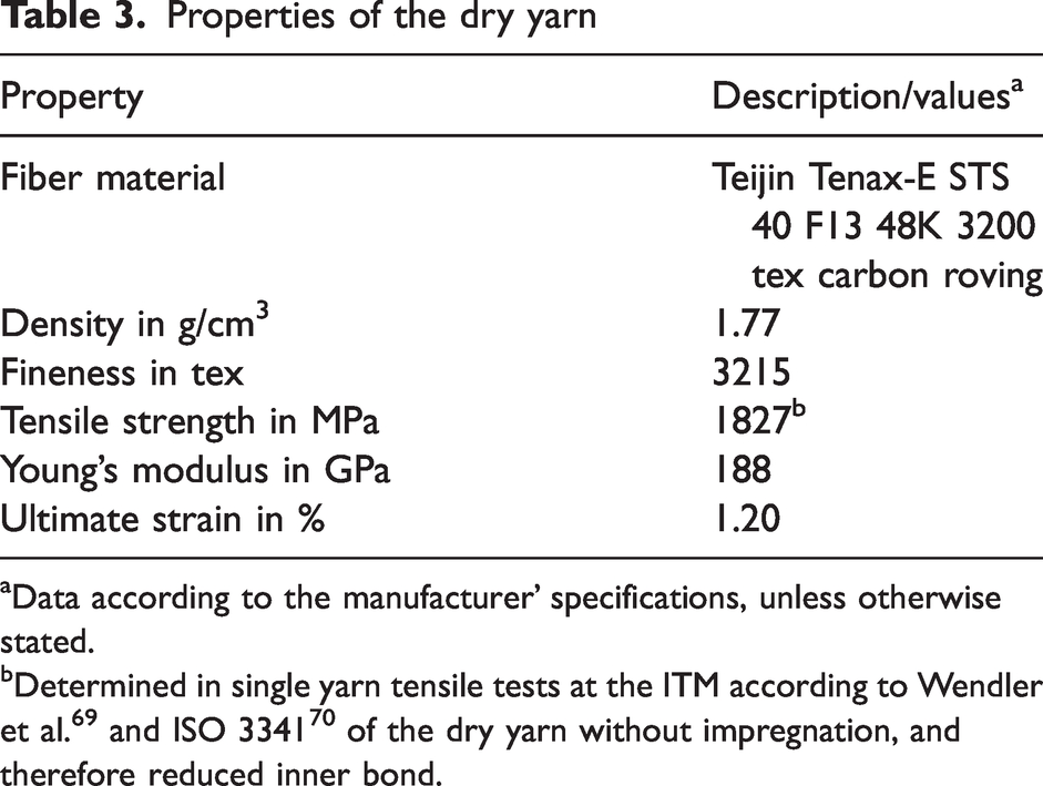
Data according to the manufacturer’ specifications, unless otherwise stated.
This study focuses on carbon fibers, due to their corrosion resistance and high tensile properties.
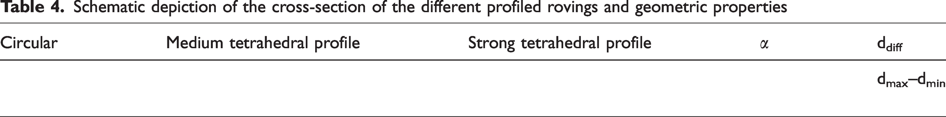
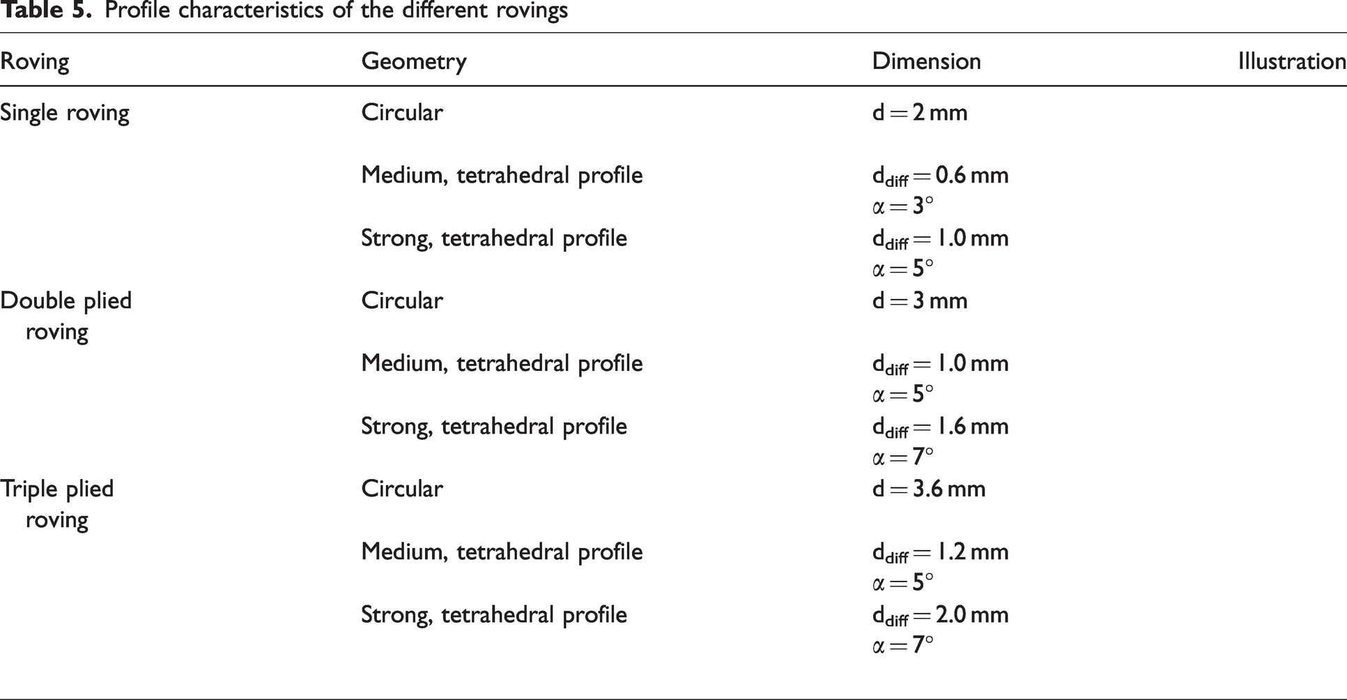
Impregnated rovings consisting of one to three plied multifilament yarns with different profile configurations were manufactured according to the process described in Penzel and colleagues66,67 (impregnation, consolidation and profiling), and subsequently analyzed. Thus, each variant was combined with the impregnation agent called TECOSIT CC 1000 (CHT Germany GmbH, Germany), which is an aqueous polymeric dispersion based on polyacrylate, with a solid content of 47 ± 1% and a linking temperature of about 160°C. The profile characteristics of the different investigated rovings series are presented in Table 4. Thus, the geometry of the tetrahedral profiled rovings is defined by the difference between the minimum and maximum diameter in a profile dent (smallest cross-section; given by Table 6), resulting in a specific deviation angle of the linear filament orientation. Thus, the angle α is determined as the tangent between the distance between two neighboring profile dents in the vertical and horizontal plane (10 mm), and the difference between the minimum and maximum diameter. The difference profile (medium, strong tetrahedral profile for different filament count) is thus created by adjusting the difference between the profiling elements of the laboratory profiling unit described in Penzel and colleagues.66,67 Impregnated rovings without profile show a circular geometry, and were produced without profiling elements. The diameter changes in accordance with the ply count of the rovings.
Schematic depiction of the cross-section of the different profiled rovings and geometric properties
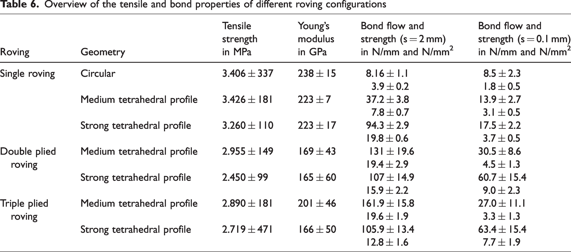
Overview of the tensile and bond properties of different roving configurations
In order to investigate the influence of the ply count and roving geometry on the tensile and bond properties, differently plied rovings with circular as well as medium and strong tetrahedral profiles were produced with a continuous working laboratory profiling unit. The function of the laboratory unit is described in Penzel et al. 67
The schematic cross-section of the different profile geometries is presented in Table 5.
Profile characteristics of the different rovings
An exemplary microscopic analysis of the roving structure and the influence of the profile on the structural roving properties for single rovings with strong profile is presented in Penzel et al. 67
Concrete matrix
Fiber-based reinforcements are very often embedded in cementitious matrices with small maximum grain sizes. 5 In the course of the initial trials on profiled yarns presented here, a fine concrete dry-mix (called BMK 45-220-2, consisting of binder material BMK-D5-1 from Dyckerhoff, Germany; the gravel KSM Compact III by KSM-Babst GmbH, Germany; fine sand BCS 412 from Strobel, Germany; sand 0/2 from Ottendorf, Germany; superplasticizer PCE SP VP-16-0205-02 from MC-Bauchemie, Germany, and water) was used for the pull-out tests at the Institute of Construction Materials (IfB) of TU Dresden. The concrete has a maximum grain size of 2 mm, and the concrete properties were determined on 40 × 40 × 160 mm³ prisms according to DIN EN 196-1. Thus, the concrete showed a compressive strength of 105 MPa or greater, and a bending tensile strength of 11.5 MPa or greater.
Asphalt mastic
For evaluation of the pull-out behavior in asphalt, a pourable asphalt was used for specimen production.
The asphalt mastic has a maximum grain size of 11 mm, and consists of the following components: dolomite stone powder from Wünschendorfer Dolomitwerk GmbH (Caaschwitz, Germany); different Rhyolit/Andesit mixtures from Steinbruch Altenhein (Altenhein, Germany); natural sand from MDB Mitteldeutsche (Laußig, Germany); greywacke from Hartsteinwerk Unterberg (Unterberg, Germany). This material was tested and used for road pavements at the Institute of Urban and Pavement Engineering of TU Dresden.
Test program and test set-up
Tensile tests on single impregnated rovings are a fast method to analyze the change in load-bearing capacity as a result of further processing (e.g. profiling). The tests were conducted on the basis of DIN EN ISO 10618 (see also Wendler et al.). 69 The free yarn length was 200 mm. The ends of the profiled yarns were clamped with metal clamps with a steel file cut. For this purpose, the single impregnated rovings (without profile, with profile, and extracted rovings from a reference textile) were resinated in the clamping area using metal molds, and clamped between two pneumatic pressured steel clamps (50 × 60 mm2), with a file cut surface at 35 bar. Figure 5 shows the tensile test specimen.
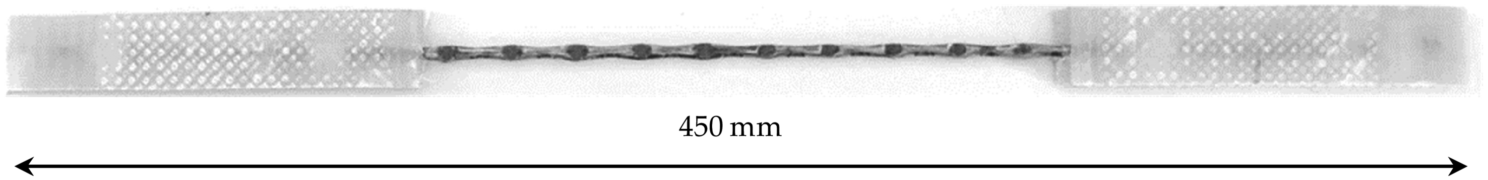
Tensile test specimen of a profiled roving with epoxy-resinated ends.
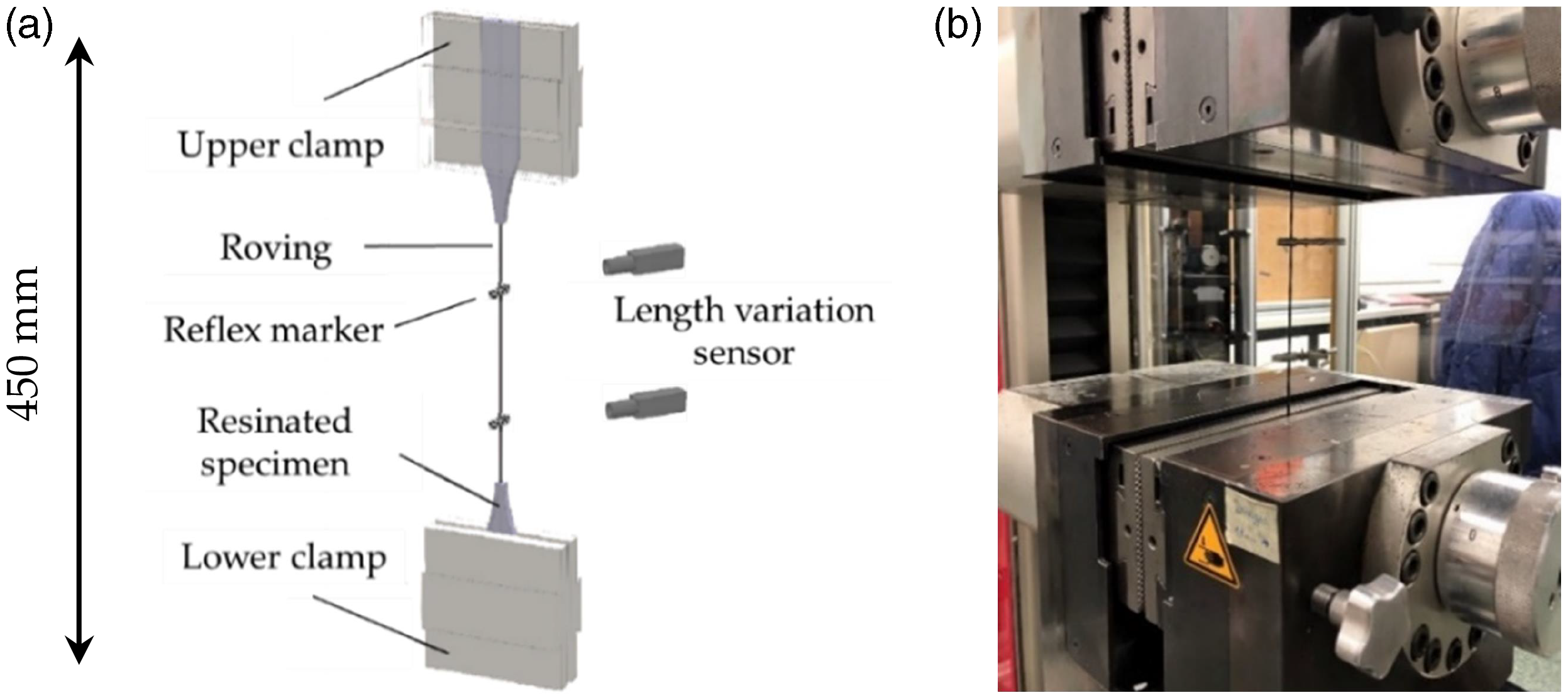
Figure 6 shows the principle of the clamping on the left and the test facility on the right. All tests were performed with the testing machine Zwick 100 from ZwickRoell GmbH & Co. KG (Germany). The test speed was 3 mm/min. The entered force was measured with a 100 kN force tensor, and the elongation of the roving was determined with an optical laser system consisting of two length variation sensors and reflex markers, which were fixed on the roving prior to the test. The Young’s modulus was calculated between 0.15% and 0.9%.
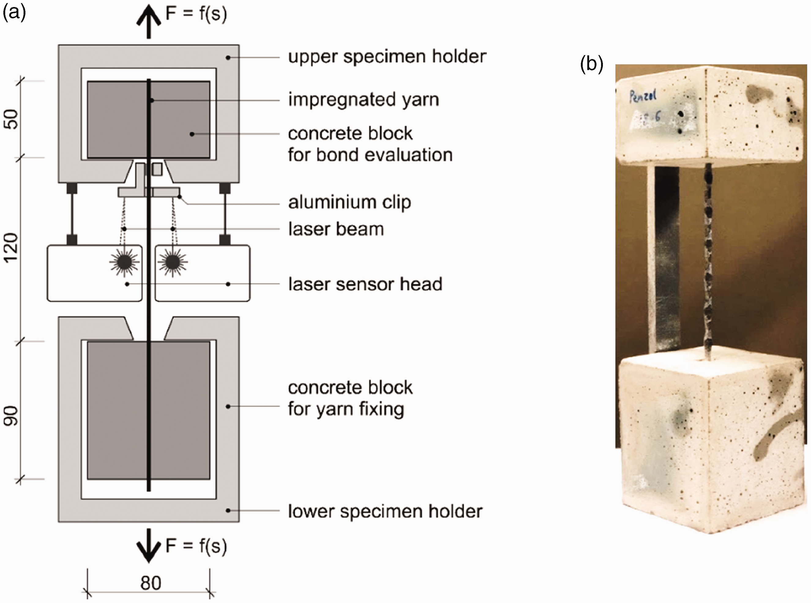
There are various possibilities for the characterization of the bond between textile reinforcement and concrete; however, there is no standardized test method yet. The focus of this study was to investigate the influence of the roving geometry on the general bond behavior for an overall comparison. Therefore, single YPO tests were conducted at the IfB in order to analyze the characteristic bond–slip behavior of individual rovings with different profile properties.10,46,67 In this type of experiment, individual rovings with different configurations were embedded in cubic concrete blocks using the self-compacting fine-grained concrete BMK 45-220-2 in a cube formwork. One specimen consisted of two centered concrete blocks at the yarn ends, and a free yarn segment of 120 mm in between the blocks. This was a clearly defined area in which composite failure could occur. The specimens were stored for 7 days underwater and stored for an additional 21 days in a climate chamber (20°C and 65% relative humidity). More details about the specimen production are given in Penzel and colleagues66,67 and Waldmann et al. 68 The upper block had an embedment length of 50 mm. The lower block provided an increased embedment length of 90 mm at the bottom roving section for a defined roving anchorage. The cubic concrete cover was 40 mm. The concrete specimens were fixed in an upper and lower steel specimen holder, and the pull-out force–slip deformation curve was measured by a single-sided pull-out in the upper concrete block, with a controlled quasistatic load (Figure 7). The pull-out (slip) deformation was measured by an optical system consisting of laser sensors and aluminum clips, which were fixed to the yarn. All tests on the carbon reinforced concrete specimens took place at 20°C, 28 days after casting.
In order to investigate the pull-out behavior in asphalt, the YPO test set-up was adapted according to Figure 8.
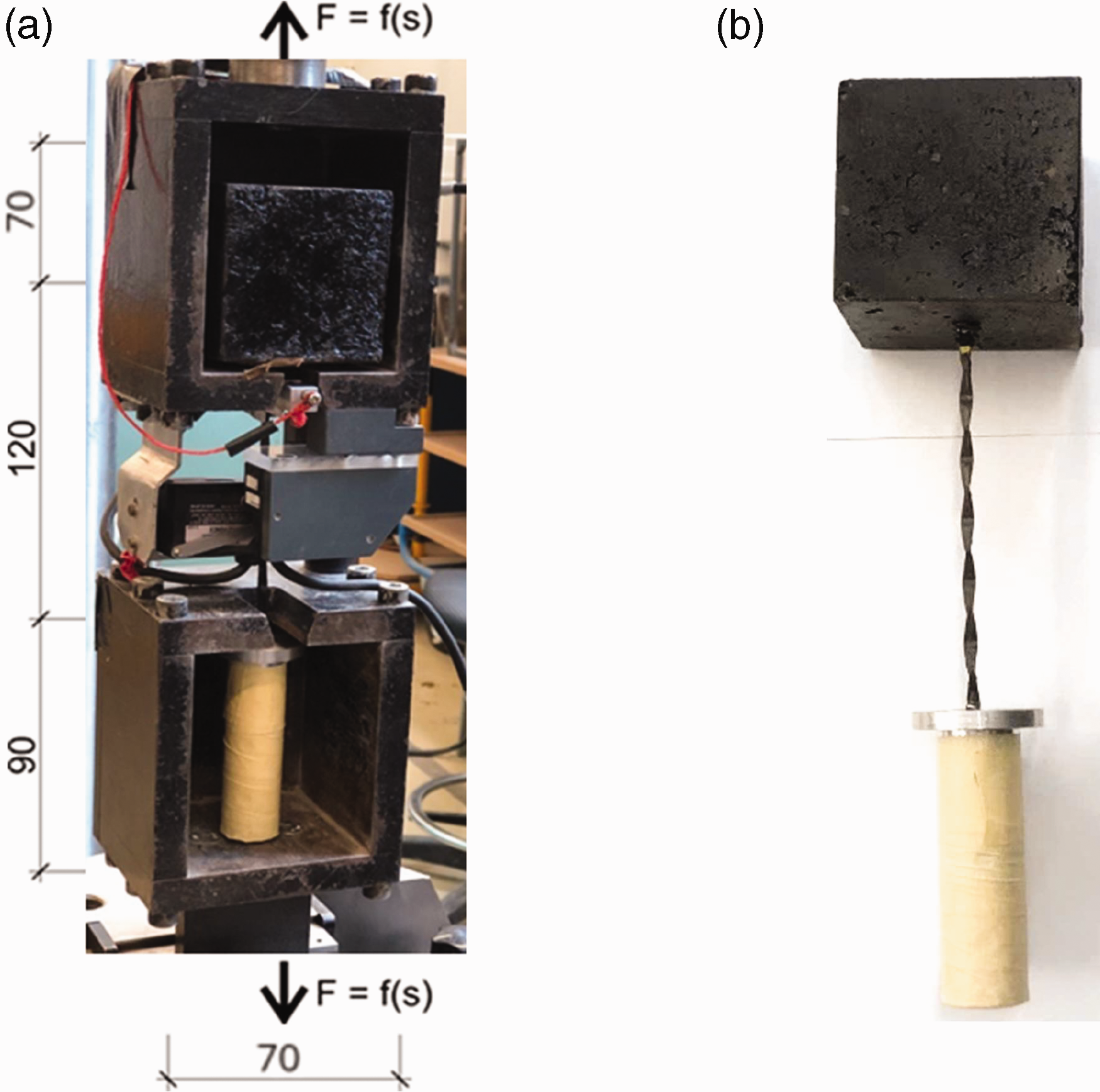
For the asphalt pull-out test specimens profiled rovings were embedded in the asphalt matrix at 180°C in a metal formwork with the cubic dimensions 70 ×70 × 70 mm³ on the pull-out side and 50 mm embedment length of the roving. For full anchorage of the roving in the lower specimen holder, the roving was embedded in epoxy resin within a 90 mm long metal tube (16 mm outer circumference, 10 mm inner circumference). The free yarn length was 120 mm. The testing method was the same as for the YPO-concrete tests.
Results and discussion
Tensile strength of single rovings
The following diagrams in Figure 9 illustrate the mean values of the tensile test results of the different series of fiber strand configurations made of plied rovings with their standard deviation. For each series, at least seven single specimens were tested according to DIN EN ISO 10618. 69 An important part of the study was a comparison between tensile properties of impregnated rovings with a circular cross-section, and impregnated rovings with a defined tetrahedral profile. This was to conclude the influence of the profile on tensile properties of the roving. Thus, the determined tensile strength (N/mm2) refers in all tests (dry and consolidated rovings) to the measured force (in N) divided by the dry filament area of 1.81 mm2 multiplied by the plied roving number (1/2/3 × 1.81 mm2). The composite dimensions of the impregnated rovings were neglected for the calculation of the tensile strength and Young’s modulus, because only the filaments transmit the high tensile load (but a similar fiber volume fraction can be assumed). The Young’s modulus is the quotient of the absolute tensile strength difference and total elongation in the range of 0.15% and 0.9% elongation.
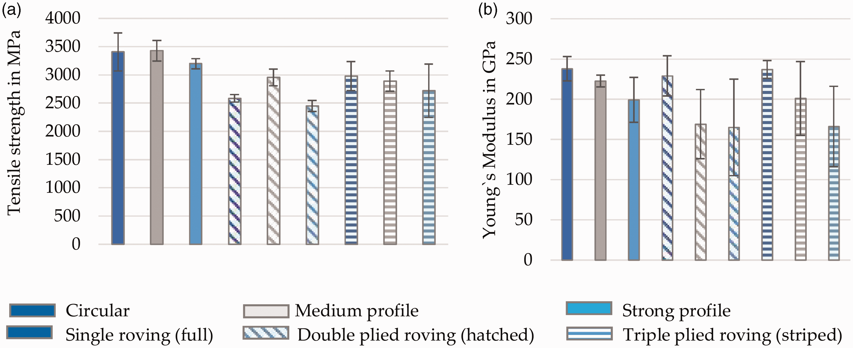
Tensile strength (a); and Young’s modulus (b) of plied rovings with different profile configurations.
The single rovings with a circular profile have the highest tensile properties, with a tensile strength of approximately 3400 MPa and Young’s modulus of approximately 235 GPa. Overall, the plied rovings with circular profile in comparison with the tetrahedral profiled rovings show the highest Young’s modulus in a range of 230–240 GPa due to the linear orientation of the carbon filaments. For each series of differently plied rovings, the rovings with a circular profile show a slightly higher tensile strength (approximately +5%) compared with the tetrahedral profiled rovings, except for the double plied rovings with a circular profile. Thus, the tensile strength of singe rovings is in the range of 3200–3400 MPa, for double plied rovings it is in the range of 2550–2950 MPa, and for triple plied rovings it is approximately 2700–3000 MPa. In all differently plied series, the rovings with a strong tetrahedral profile show a decrease in tensile strength of 5–10% due to the reorientation of the carbon filaments, and the slight deviation of their linear course, resulting in a minor shear force load and premature failure. No evident fiber damage was detected in microscopic analysis. A similar correlation is shown in the Young’s modulus. The differently plied rovings with a strong tetrahedral profile show the lowest tensile properties in a range of about 165–200 GPa, in which the triple plied rovings show the lowest Young’s modulus at 165 GPa, and the single rovings show the highest Young’s modulus at c. 200 GPa. A possible reason is the deviation of the linear filament course and the increased shear load. An apparent general trend is the reduction in tensile properties with increased plied roving count, due to a higher filament count, and therefore more difficult uniform load distribution, and load transmission among the edge and core filaments in dependence of a uniform impregnation and high inner bond. However, the tensile strength of the plied and profiled rovings is comparatively high, and shows an overall high utilization of the tensile load potential due to the material appropriate shaping process and tetrahedral geometry. Thus, all specimens show a sudden brittle fracture of the complete roving structure in the free yarn length, and complete failure during the tensile test, indicating an even load distribution and not core–sheath failure. Furthermore, the rovings show no apparent structural elongation, making them suitable for an initial load transmission.
Bond behavior of concrete embedded rovings
In order to compare the bond behavior of the differently plied rovings with different profile configurations, pull-out tests were carried out at the Institute of Construction Materials of TU Dresden, according to the described test set-up (see the section on Asphalt mastic above). On average, four test specimens per configuration were tested at the same test conditions (see the section on Test program and test set-up above).
The following diagrams in Figures 10 and 11 show the averaged bond stress-slip deformation curves and the bond stress of the rovings at specific slip levels. Thus, the bond stress (N/mm2) is equal to the specific pull-out load (N/mm) divided by the circumference of the dry filament area (mm) of the plied rovings (mantle surface, contact area with concrete). The specific pull-out load (in N/mm), refers to the measured bond force (N) divided by the bond length (50 mm). Because no tested specimen showed shear cone failure or partial separation of concrete from the sample surfaced, the initial bond length was 50 mm.
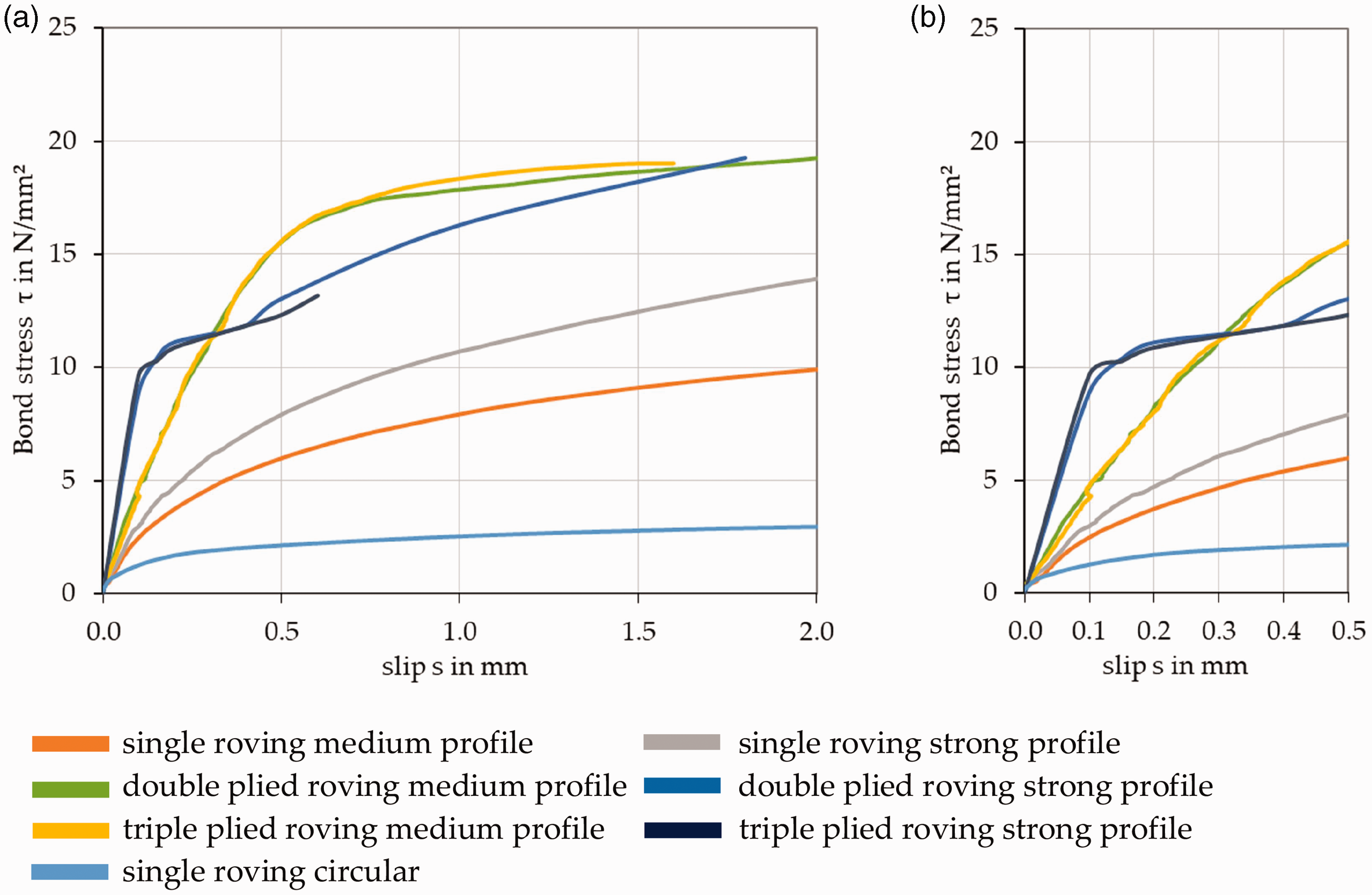
Bond stress-slip deformation curve of plied rovings with different profile configurations up to 2 mm slip (a) and 0.5 mm slip (b).
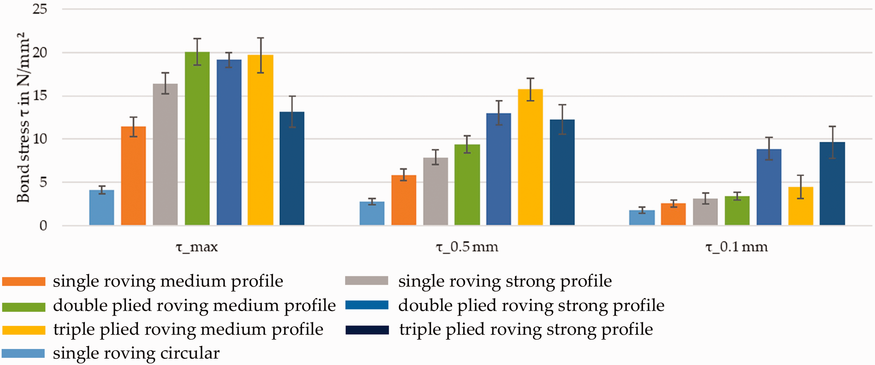
Specific bond stress of plied rovings with different profile configurations at a defined slip.
The single roving with a circular profile shows with a maximum bond stress of around 4 N/mm2, the lowest bond properties. Thus, the bond stress of the circular profiled rovings is similar for the single, double plied or triple plied rovings. With increased roving ply count and profile, the rovings show an improved bond behavior. Thus, single rovings with a strong profile already show a maximum bond stress of about 16 N/mm2, a 400% increase compared with unprofiled rovings. With increased ply count, a more dominant profile can be produced resulting in a further increase of the bond behavior. The double and triple plied rovings show for the medium and strong profile an almost identical bond behavior. Thus, the double plied rovings with a medium tetrahedral profile achieve at around 20 N/mm2 the highest maximum bond stress, and therefore a more than 500% increase compared with rovings with no profile. In comparison with Kruppke et al., 10 in which rovings without a profile show a maximum bond stress of less than 3 N/mm2 under the same test conditions, the triple plied rovings with a medium profile show a bond stress of 16 N/mm2, which is more than 500% higher (at 0.5 mm slip). The plied rovings with a strong tetrahedral profile have a slightly reduced maximum bond stress due to premature splitting of the concrete embedment block (presented in Table 7), yet they show a much steeper increase in the bond stress-slip deformation curve and achieve with about 8–9 N/mm2 the highest bond stress at 0.1 mm slip. Compared with rovings with no profile (1.5 N/mm2), they show an up to 600% increased bond for the initial slip. This makes them especially suitable for initial load transmission and reduced bending or crack openings. However, the premature failure due to the splitting of the concrete block results from the strong profile, which introduces orthogonal splitting tensile forces. Therefore, the triple plied rovings with a strong profile are suitable for concrete parts with concrete cover greater than 5 cm; that is. new building constructions. A summary of the mechanical performance (tensile and bond properties) of the different roving configurations comparatively studied in this paper is given in Table 6.
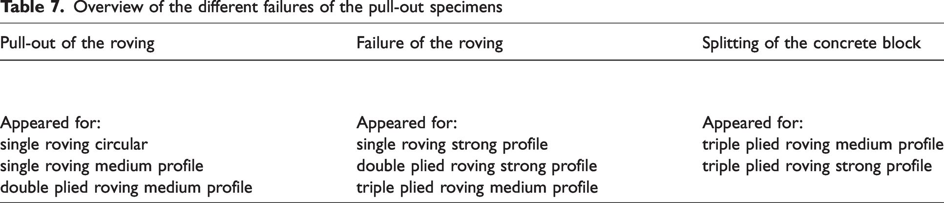
Most of the tested specimens showed a failure of the roving (presented in Table 7), indicating a strong mechanical interlock and sufficient anchorage length for complete load transmission between the concrete block and carbon roving. The rovings without a profile and medium tetrahedral profile also showed a pull-out of the roving, whereas the triple plied rovings with a strong tetrahedral profile sometimes showed a splitting of the concrete block. No shearing of the roving profile was indicated, due to a uniform roving and filament structure without a core-sheath-structure.
Overview of the different failures of the pull-out specimens
The evaluation shows that the profiled rovings with high yarn cross-sections (e.g. triple plied rovings) may be more suitable for the reinforcement of matrices with low brittleness; for example, asphalt and asphalt base layers. Due to the bitumen content in asphalt, cracking is reduced and, in particular, the significantly larger maximum grain size dimensions in the asphalt base layer (up to 22 mm) with subsequent compaction require a robust and strongly profiled reinforcement structure for a slip-free bond.
However, asphalt is also characterized by a strongly temperature-dependent material behavior. At low temperatures, asphalt achieves strengths comparable to concrete (e.g. –10°C, winter case), whereas at high temperatures (e.g. 30°C, summer case), asphalt exhibits a viscous state.19–21
In order to evaluate the bond properties of those promising, profiled triple plied rovings, first pull-out tests in asphalt have been performed according to the test set-up of the concrete pull-out tests (see Figure 12). Thus, only a single specimen was tested for each temperature (the test specimen was acclimatized for 24 h), in order to get a first impression of the bond behavior in asphalt mastic. The bond behavior of profiled rovings in asphalt base layers has not been the focus of previous studies, and is therefore unknown. Furthermore, fundamental investigations, especially with regard to fatigue behavior will be part of future studies.
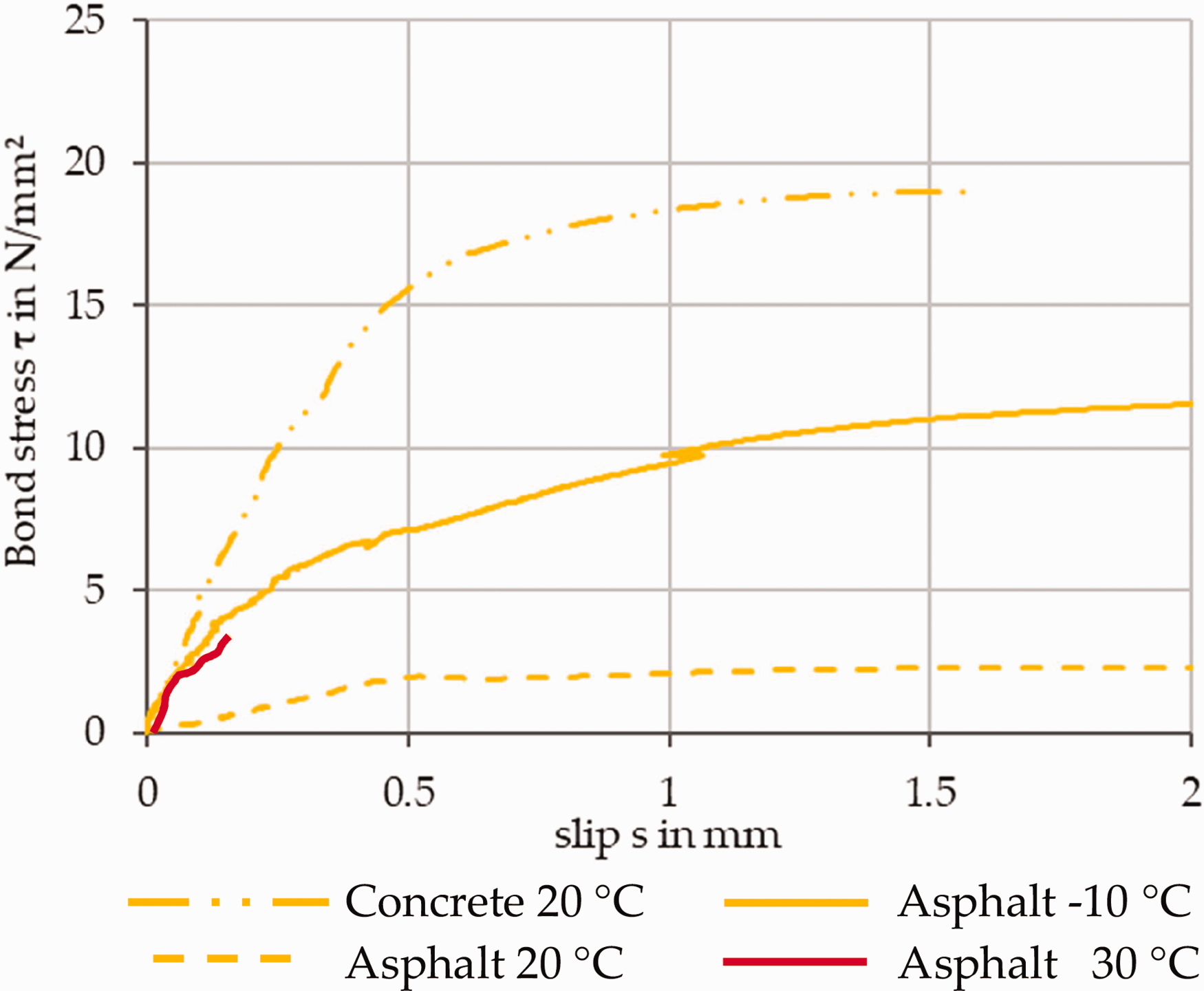
Bond stress-slip deformation curve of triple plied rovings medium profile in concrete and asphalt at different temperatures.
The test results show that at –10°C and 20°C, the profiled plied rovings in asphalt are almost comparable to the bond behavior in concrete, up to a pull-out of 0.2 mm. At a temperature of 30°C, which is a maximum temperature of the lower lying asphalt base layer, 25 the bond behavior in asphalt is significantly reduced (reduction by a factor of 4 from approx. 10 N/mm2 to approx. 2.5 N/mm2 for triple plied profiled rovings). For larger slip deformations, the profiled rovings can only transfer low bond forces compared with concrete, but only minimal displacements and strains occur in the asphalt base layer, so that only the initial bond up to a maximum pull-out of 0.2 mm is relevant. In addition, the relevant failure of the asphalt base layer occurs mainly in winter at low temperatures and increased brittleness of the asphalt base layer, so that the bond behavior at low temperatures is particularly relevant for crack formation or prevention by additional reinforcement.19–21,25
The presented test method for investigation of the bond behavior gives a first impression to qualify the performance of the profiled rovings in asphalt mastics, yet it does not directly translate to textile performance in actual roadways or structures. Therefore, further tests such as the cyclic 4-point bending test and split tensile swell test will be part of future studies.
Conclusions
This study shows that the newly developed impregnation forming technology is suitable for the production of tetrahedral profiled rovings with high tensile and bond properties, and that the tensile and bond properties vary in dependence of the roving ply count and profile characteristics, as well as the surrounding matrix and temperature.
Thus, the strong profiled rovings show a slight decrease in tensile behavior by approximately 10–20%, yet they show an up to 600% higher initial bond stress. This makes them perfectly suitable for highly stressed concrete components with concrete cover greater than 5 cm and limited bending, especially in areas of new building constructions, where they represent a sustainable and material efficient alternative to conventional steel reinforcements such as rebars or filigree mats. The high bond properties result in reduced anchorage lengths necessary for complete force transmission between the surrounding concrete and the textile reinforcement, and therefore higher material efficiency (necessary anchorage length depends on the application and load of the structure).
Due to induced splitting failure of the rovings with strong profile and high ply count in combination with the brittle concrete matrix, the triple plied rovings are more suitable for use in matrices with reduced brittleness, such as asphalt. Thus, the profiled rovings exhibit a temperature-dependent bond behavior, with an increase of more than 500% at low temperatures compared with high temperatures. Due to their robust structure and high tensile and bond properties they promise to increase significantly the service life of roadways when used as reinforcement for asphalt base layers. Therefore, further fundamental investigations with regard to fatigue behavior, such as bending tests and split tensile swell tests, will be part of future studies.
The plied rovings with a medium profile show only a 5–10% reduction in tensile properties, but a more than 500% increase in maximum bond stress, and no splitting of the concrete block. This makes them especially suitable for applications with reduced concrete cover and increased bending, such as floor or ceiling panels, balconies and bridges. Thin roving structures can be used for structural reinforcement, such as walls.
In summary, the newly developed plied rovings, with a tetrahedral profile and continuous fiber course, show a significant increase in the bond behavior in combination with a very high utilization of the tensile load potential of the carbon filaments in concrete and asphalt matrix, without premature shearing of the profile in contrast to core-sheath structures created with conventional subtractive or additive processes.
Furthermore, the results of this study emphasize the abundant possibilities for modifying the roving properties by profiling. Due to the different influencing parameters, such as filament count, profile geometry, impregnation agent, consolidation, and so on, it is possible to adjust the load bearing behavior according to an application-specific design of the carbon reinforced concrete structures, as well as for applications in asphalt. Additional promising application fields for profiled roving structures with controllable bond properties are components with defined earthquake resistance, impact properties, waterproofness, and prestressed structures.
Footnotes
Acknowledgements
The IGF research projects 21375 BR and 22609 BG of the Forschungsvereinigung Forschungskuratorium Textil e.V. are funded through the AiF within the program for supporting the Industriellen Gemeinschaftsforschung (IGF) from funds of the Federal Ministry for Economic Affairs and Climate Action on the basis of a decision by the German Bundestag.
The article processing charges (APCs) were funded by the joint publication fund of TU Dresden, the Medical Faculty Carl Gustav Carus, and the SLUB Dresden.
Declaration of conflicting interests
The author(s) declared no potential conflicts of interest with respect to the research, authorship, and/or publication of this article.
Funding
The author(s) received no financial support for the research, authorship, and/or publication of this article.