
Abstract
Twist plays an important role in textile technology, particularly in the production of staple yarn structures. Due to the higher yarn quality and flexibility of the process, most short staple fiber yarns are produced in the ring spinning process in comparison to other high-speed spinning processes, such as rotor or air jet spinning. To impart twist in the yarn, the ring/traveler system, rotor and air jet nozzle are used in the ring, rotor and air jet spinning processes respectively. However, the productivity of the ring spinning process is limited significantly due to the frictional heat generated between the ring and traveler, especially at higher angular spindle speeds, which is crucial for the spinning of man-made fibers. This paper aims to describe the recent developments and solutions for increasing productivity in the ring spinning process in a systemic way. To reduce the friction, different topologies and surface modifications in the ring/traveler system were made to increase the angular spindle speed of maximum 23,000 rpm. To eliminate the friction, the twisting element was made of an air bearing or magnetically elevated rings were developed by replacing the ring/traveler system completely, thus permitting a higher angular spindle speed of up to 50,000 rpm. Further approaches deal with cap, loop and nova spinning or Nu-Torque technology to reduce yarn tension or residual torque in the yarn, respectively. The results of the presented work reveal the potential of different developments, especially in the field of twisting system, so that the productivity of ring spinning can be increased drastically.
Keywords
According to the International Textile Machinery Shipment Statistics (ITMSS), the shipment of new short staple spindles rose by +27% in 2022 in comparison to 2021. 1 About 73% of short staple fiber yarn has been produced with ring spinning machines, whereas the production of rotor yarn and air jet yarn was only 25% and 2%, respectively. 2 These statistical data confirm the universal importance and the dominant market position of ring spinning machines in short staple yarn production. The high quality of yarn and the flexibility of the machines make ring spinning the most important spinning process compared to other spinning systems, such as rotor spinning, air jet spinning, etc.
Ring spinning offers numerous clear advantages:3,4
the spinning process is applied universally for the production of a wide range of yarn counts and textile materials; it produces the best quality of yarn with optimum properties regarding yarn structure and tenacity; it is uncomplicated and easy to operate and control during spinning; know-how for handling the machine is old, well-established and accessible to everyone; it is the most flexible spinning method considering the volume (blend and batch sizes).
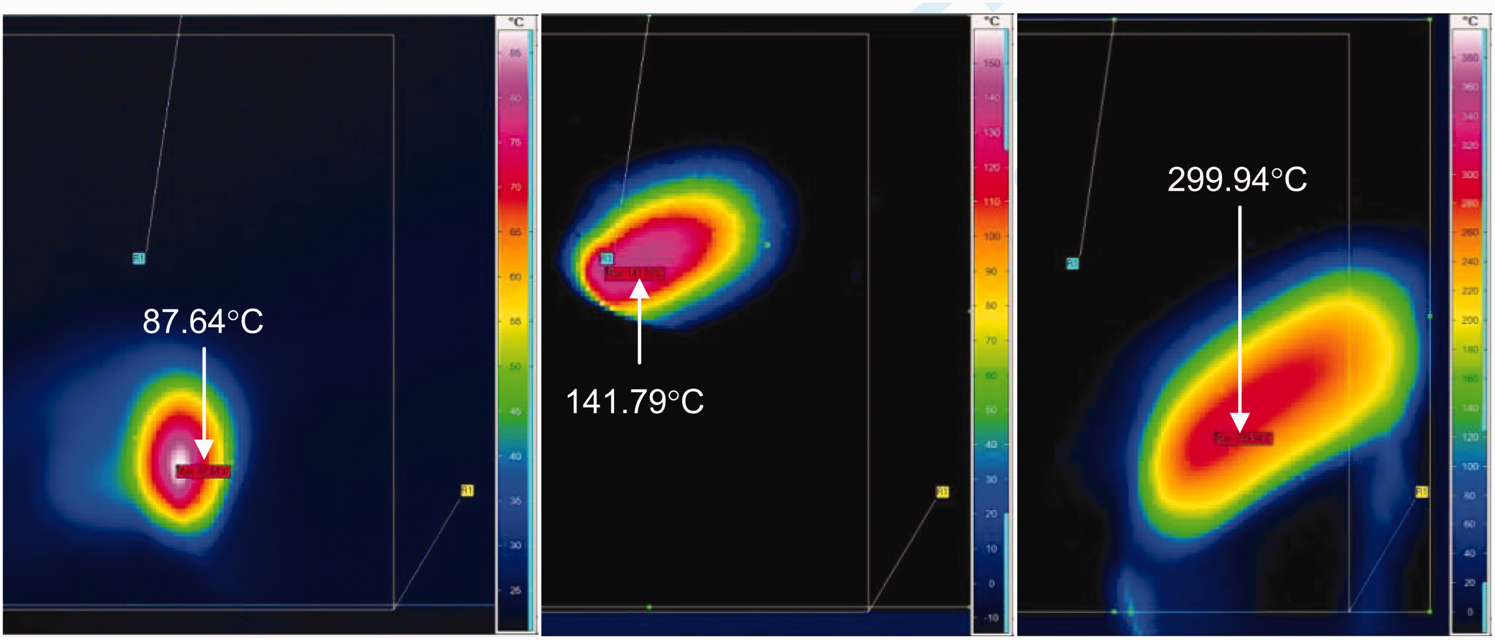
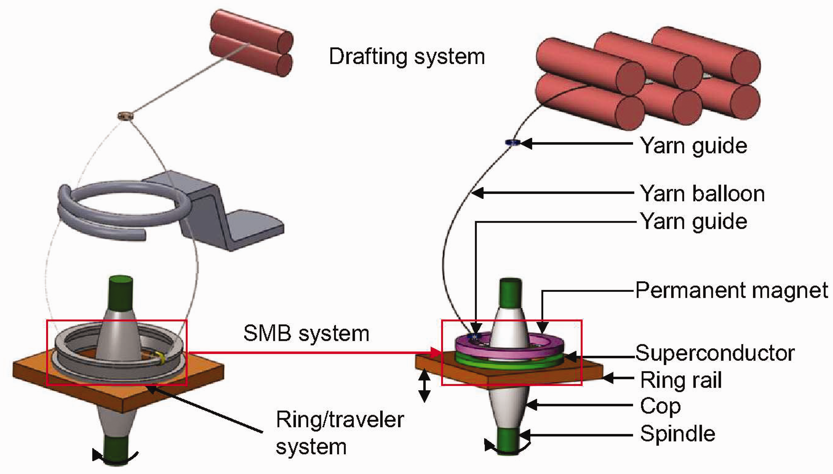
In the ring spinning process, as illustrated in Figure 1, the fibrous material is fed as an input material in the form of a roving into the drafting system to attenuate according to the required yarn count. Then the drafted roving is delivered through the yarn guide into the ring traveler system in order to twist the yarn and wind it on to the cops. The attenuated fibers are held together by the insertion of twist in order to impart the tensile strength in the yarn. The traveler has no drive of its own; it is dragged with the spindle via the yarn attached to it. Each rotation of the traveler on the ring in the ring/traveler system inserts one twist in the yarn. The number of twists in the yarn during spinning is calculated from the ratio of the spindle speed and delivery rollers, that is, if the spindle speed is defined as
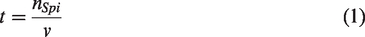
Ring spinning machine and its functional principle. 5
The rotation of the traveler lags somewhat behind that of the spindle due to the relatively high friction of the traveler on the ring and the air resistance of the yarn balloon between the yarn guide and the traveler. The difference in speed between the spindle and the traveler results in winding on the cops. The length wound up on the cops over time corresponds to the difference in peripheral speeds of the rotating traveler and spindle, which corresponds to the length delivered at the delivery rollers. The winding or delivery rate

The ring rail moves up and down during the cop’s formation. The slow upward motion of the ring rail produces parallel winding of the yarn, whereas the quicker downward movement produces cross-winding, which is important for easy unwinding.
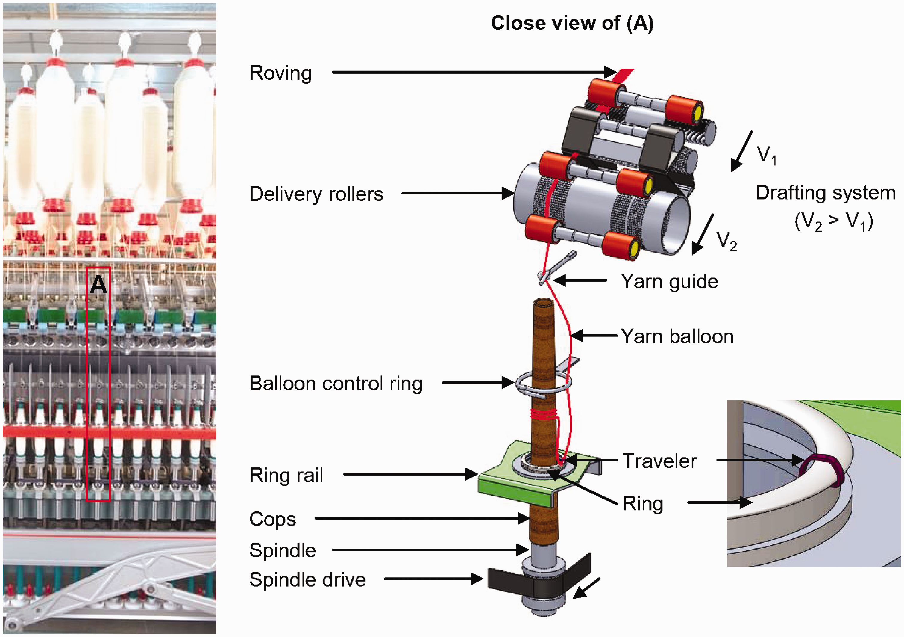
Although the winding rates of yarn depend on the spindle speed, they are directly correlated to the rotational speed of the traveler, which limits the productivity of ring spinning. Figure 2 shows the production of ring spinning in comparison to other spinning processes.
Production rate of ring spinning. 7
The productivity of ring spinning is 1/10th and 1/20th times lower in comparison to that of rotor and air jet spinning systems.6,7 The main reasons behind this are the ring/traveler twisting system, yarn tension and yarn breakage. The friction as well as the wear between the ring and traveler increase sharply at higher spindle speeds. During spinning, high contact pressure occurs between the ring and traveler. This pressure includes strong frictional forces, which in turn generate heat. This heat has to be dissipated at a faster rate to avoid quicker wearing out of the ring/traveler system. However, the low mass of the traveler does not permit the dissipation of the generated heat in a short time, which results in the wear of the traveler and ring.5,8,9
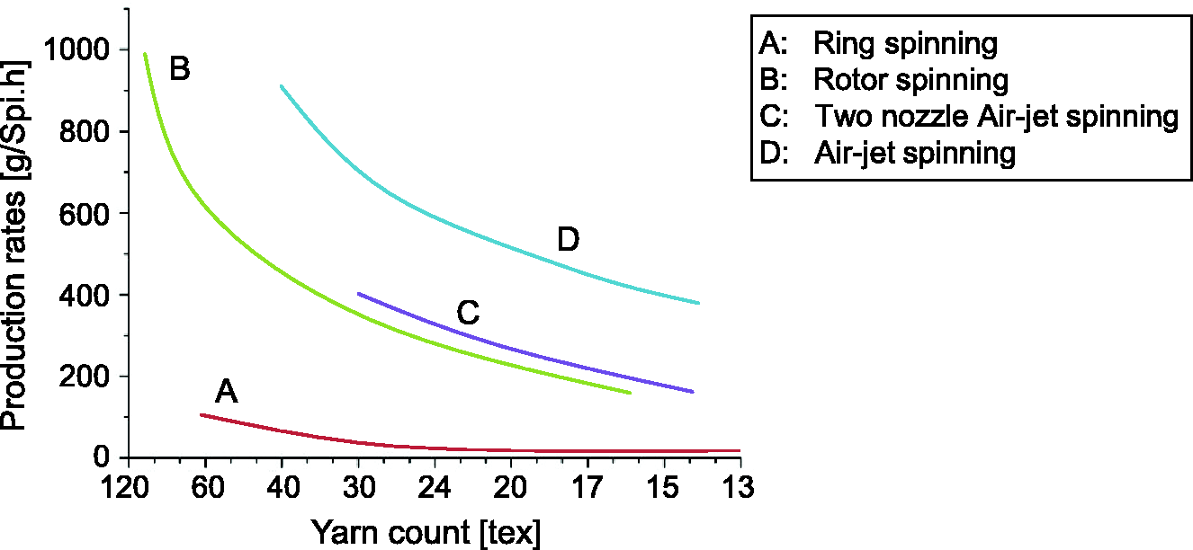
The investigation with the help of an infrared camera at the Institute of Textile Machinery and High Performance Material Technology (ITM) determines that the temperature increases quickly due to the friction between the ring and traveler, depending on the spindle speed. For example, the temperature of the traveler increases up to 300°C within a very short time at an angular spindle speed of 20,000 rpm (Figure 3). As a result, the operating speed of the traveler is limited to a maximum of 50 m/s. 3 Moreover, this is detrimental to the process, particularly when spinning medium- and high-twist cotton and blended yarns in medium and fine counts, as well as man-made fibers. The wear-out problem of the traveler deteriorates the yarn, especially by increasing the hairiness.
Measurement of traveler temperature at spindle speeds of 10,000, 15,000 and 20,000 rpm. 5
The abrasion stresses acting on the traveler at higher spindle speeds are so high that it must be replaced at regular intervals, requiring more down time and personnel effort. The changing of worn rings is also complicated and time-consuming, as they need to be centered for every spindle position.
Moreover, as the centrifugal force acting on the traveler is directly proportional to the weight and angular speed of the traveler, the yarn tension in the balloon is strongly dependent on the traveler speed and the height of the balloon for a given yarn count. High traveler speeds and greater balloon heights lead to very high yarn tensions in the balloon.
Thus, the acting forces among the ring, traveler and yarn cause a significant limitation of productivity in the ring spinning process, mainly in the ring/traveler system. The important limiting factors can be summarized as follows:
the frictional heat between the traveler and ring (melting points in man-made fibers); the wear of the ring/traveler system, especially on the contact surface of the traveler and ring; the frictional heat between the balloon control ring and the yarn (melting points in man-made fibers); the increased yarn tension resulting from higher balloon tension at higher spindle speed, which causes end breakages.
In order to reduce or eliminate the frictional heat as well as the damage in the ring/traveler system, either the friction has to be reduced or the existing ring/traveler system should be eliminated. Moreover, the productivity can be increased by reducing the yarn tension.
The recent advancements and their solutions for the high-speed ring spinning process can be categorized as follows:
developments in the ring/traveler system to reduce friction; developments of new ring/traveler systems to eliminate friction; concepts of reducing yarn tension; adding a false twisting device; compact ring spinning.
Developments in the ring/traveler system to reduce friction
There are a number of research efforts modifying the ring/traveler systems to increase the productivity of ring spinning machines. The aim of the research activities was to reduce the frictional problem between the ring and the traveler. In the following description, the modifications of the ring/traveler system implementing different topologies, material combinations or coating materials are briefly described.7,10–19
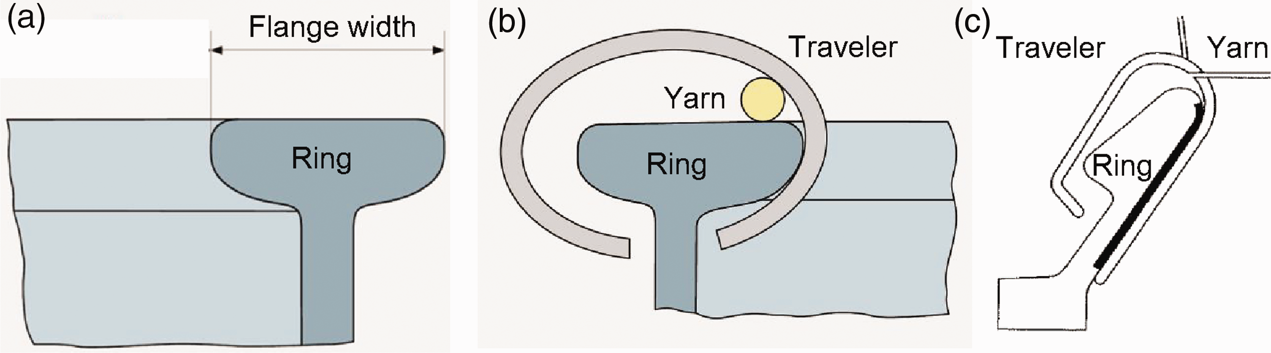
Different topologies of the traveler and ring to reduce the forces acting in the twisting system. For example, the most commonly used T-flange (Figure 4(a)), anti-wedge ring (Figure 4(b)), elliptical traveler (DE 19637475, DE 10025191A1, DE 198 24 079 C2, US 6568164 B2), C-, N- SU (Figure 4(c)) and inclined flange ring (Figure 5).
Different material combinations of the ring/traveler such as steel, synthetics and ceramics (DE 3723057C1, EP 657566A1), as well as special surface modifications of the ring and traveler to reduce their friction during operation, such as nitrogen, chromium, nickel, vanadium or their combination, (DE 3545484A1, US 5313773, US 5086615). Introduction of vibration in the ring/traveler system (DE 4038449A1).
Different topologies of the traveler and ring
The T-flange is most commonly used in the ring spinning process (Figure 4(a)). The rings are mainly defined by their inside diameters (range 36–57 mm) and the flange widths. They are also available with two-sided rings. The reverse side of the ring becomes unserviceable due to corrosion at the time of mounting. However, the ring is currently not used in the short staple industry.
The “anti-wedge” ring is the first high-performance ring. In comparison to the T-flange ring, this ring consists of a flange with a flared inside surface and is flattened on the top (Figure 4(b)). This change in shape allows, for example, the use of an elliptical traveler with a low center of gravity and larger space for the yarn passage, which can rotate on the ring at higher speed. This ring is the most widely used ring shape nowadays.
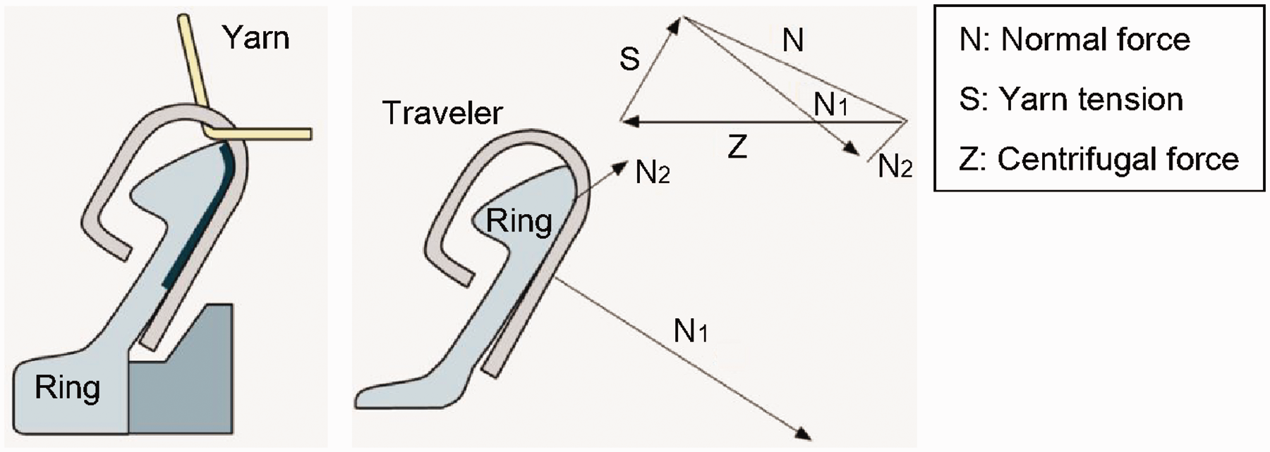
There is another type of ring is called an SU-Ring (Figure 4(c)), which was later modified by Rieter Holding AG and renamed the ORBIT ring (Figure 5).3,10 The design of this ring ensures a much larger contact area between ring and traveler compared to the T-flange ring, reducing the forces acting between the ring and the traveler and improving the heat dissipation from the contact area during operation.
The forces acting on the traveler allow the selection of a lighter traveler with the same spinning conditions. As the normal force and the centrifugal force of the traveler are not optimally distributed, a larger surface pressure results. According to Figure 5, the vector of the normal force

However, considering the scalar values of Equation (3) results in the following, that is, the sum of N1 and N2 is larger than N:

Thus, the frictional forces caused by the normal forces can be written as follows:


This means that an inclined ORBIT ring generates higher frictional forces than that of a T-flange ring with the same boundary conditions, in particular with the same traveler masses and the coefficients of friction. Therefore, lighter travelers can be used in the ORBIT ring in comparison to the T-flange rings to generate the same yarn tension required for balloon stability. Thus, the ORBIT ring offers the following important advantages to increase the traveler speed:
significantly larger contact area between the ring and traveler; the possibility of using lighter travelers; increase of traveler speed of up to 15%.
10
Different materials and surface modifications of the ring and traveler
According to patent US 5313773, the steel or alloy steel traveler is coated with ceramic materials, carbide, nitride, oxide, boride or nickel by using chemical vapor deposition or the vacuum plating method. The coating ensures higher wear resistance to the traveler. Thus, the traveler can run up to an angular spindle speed of 20,000 rpm. 11
According to the European patent (EP 657566A1), the metal ring and traveler are coated chemically or thermally with polycrystalline ceramic material. The ceramic surface contents grain boundaries, which form a storage volume for a self-generating lubricating film of fibers (Figure 6). The coating material contains the oxides of Al, Si, Zr, SiC, etc., ensuring good heat conducting capability. The wear of the ring and the traveler is thus minimized. Moreover, the facing surfaces of the ring and traveler have a different radius of curvature r, where the radius of curvature r2 of the ring is smaller than that of the traveler r1, which results in an approximate point contact between the traveler and ring. 12
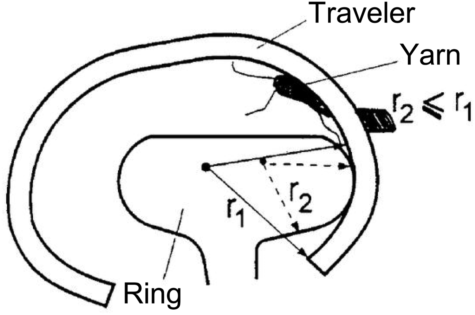
Ceramic coated ring and traveler. 12
Introduction of vibration in the ring/traveler system
Patent DE 4038449A1 describes a vibration system (one or more) integrated into the ring, which transfers the ring in the ultrasound range. According to Figure 7, the vibration device (3) is attached to the ring (2). The induction of vibration with different levels and directions to the ring (preferably through the ring rail) helps to minimize the friction between the ring and traveler, while the yarn (5) winds on the cops through the traveler (1). This system can induce the vibration in the yarn, thus varying the yarn tension and yarn quality, especially at higher speeds. 13 The induced vibration of the contact surface between the ring and traveler with different frequencies and amplitudes can reduce the frictional force and the heat generation in the contact surface of the ring/traveler system by up to 10–20%.
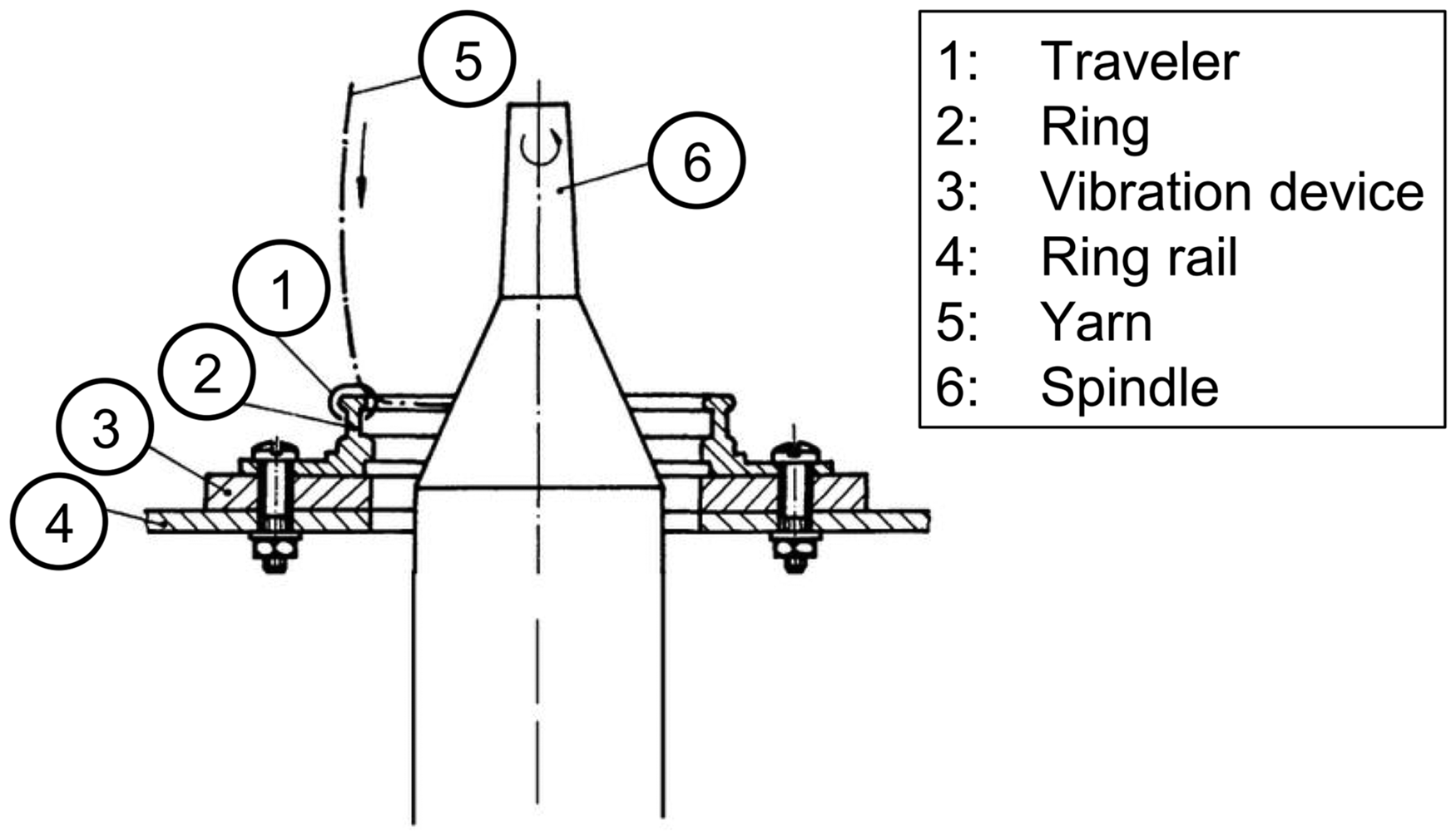
Induction of vibration to the ring through a vibration device. 13
Ring/traveler systems available on the market
The leading manufacturers of ring/traveler systems are also using some of the abovementioned methods to improve the running properties of the traveler and thus ensure a longer service life.20–23 For example, Bräcker AG, a subsidiary of Rieter Group, has modified the inclined ring with optimal force distribution and renamed it commercially as the ORBIT ring. Some travelers, such as Bräcker Saphir, Starlet and Pyrit, have an enriched steel structure with an additional finish such as an electrolytic coating of nickel plating. 20 Eadie & Kanai Co., Ltd uses steel with conically and vertically flanged sintered rings and travelers. The nylon traveler has the material properties to resist overheating and damage by using high-quality polyamide material. 21 Reiner+Fürst GmbH produces the ring and traveler using a hard material dispersion layer of boron carbide with chemical nickel to create a low coefficient of friction. 22 Oerlikon GmbH coats the ring and traveler to accumulate a thin layer of fiber debris from the yarn, which ensures less friction as well. The surface of the coating ensures a quick build-up of the fiber lubrication film. 23
However, the use of different topologies, materials or coatings for the ring/traveler systems can mainly increase the lifetime of the travelers. They can neither completely solve the frictional problem in the existing twisting system nor increase the productivity.
Developments of new ring/traveler systems to eliminate friction
Further developments refer to the new concepts of the twisting system by eliminating the existing ring/travelers, which are summarized as follows:24–33
a rotating ring (JP 54015934, EP 0026161, US 4305246, US 4161863, EP 0730054 B1); a ring with an electromagnetic bearing and an electromagnetically controlled ring (DE 2332029, US 5109659, US 7205692); an air bearing (DE 184193); rotating ring based on superconducting technology.
Rotating ring
The active driving system of the traveler is recommended in patent DE 184193 to rotate the traveler with the help of air pressure or magnetic force. 29 According to Figure 8(a), the turbine blade (d) of a rotating ring (c) is driven through two diametrically positioned air nozzles (49) in order to lift the mass of the ring, which acts as a traveler during the twisting of the yarn.
Different types of bearing rings: (a) air bearing ring and (b) magnetic bearing ring. 29
The traveler can also be driven magnetically, as illustrated in the Figure 8(b). In this case, the traveler (b) is constructed with two ring flanges (52). The two oppositely positioned iron rings (53) are connected with coils (54) for the magnetization of the traveler. The magnetization enables a lifting of the traveler for the rotation of the rings to impart twist in the yarn. In order to develop an optimized system, the circular magnetic ring should be extremely homogeneous and symmetrical, which is very complex to realize. The system uses air pressure to stabilize the ring in the transverse direction in addition to the magnetic repulsion force. Using two different types of forces to stabilize the ring complicates the rotation of the ring, as it is difficult to control the corresponding forces. The absence of the control system makes such a system uncontrollable, both at the beginning of spinning and during the yarn breakage. Moreover, the power required by such systems is economically inefficient for the ring spinning process.
Electromagnetically controlled ring
According to US patent 5109659, a magnetic ring has been developed to act as a floating ring instead of a traveler. According to Figure 9(a), a textile yarn (Y) is fed below the bottom surface of the permanent magnetic ring to a rotating bobbin. A fixed ring (B) on a ring rail (10), having a portion extending above and below the floating ring (A), prevents the displacement of the floating ring due to gravity. 30 When repulsive or opposing magnetic forces are supplied, it keeps the permanent magnetic ring (A) floating in a centered position for imparting twist to the yarn, which is fed under the permanent magnet (PM) ring and wound on the bobbin. The advantage of this invention is that there would be no friction between the floating and fixed rings. The implementation of these types of rings is found to be problematic because of the lack of a control system to center the ring electronically, especially at higher spindle speeds.
These restrictions can be solved with a light weighted rotor, which is suspended in space and actively controlled. A control system with distance sensors ensures higher precision and stabilization during operation (US 7205692). The stator consists of PMs equipped with four magnetic actuators to support the suspended ring. In the case in which the floating ring is displaced from its central position, it is picked up by the integrated sensors, which generate a signal to the power amplifiers. 31 According to Figure 9(b), the floating ring (A) has an eye on its inner middle surface, through which the yarn passes and winds onto the cops. The magnetic elevated ring eliminates the metal–metal friction between the ring and traveler. The system is claimed to rotate at up to 40,000 rpm. However, this active magnetic bearing requires sensors to adjust and regulate the position of the rotating sensor continuously. This electronically controlled magnetic system is complex and requires more space in the twisting zone.
Rotating ring with an air bearing
A twisting system was developed in 2010 in which an aluminum rotating ring with a traveler hook is suspended in an air bearing with the help of two air nozzles from Aerolas GmbH (Figure 10). 32 The braking system of the ring can also be controlled with a pressure regulator. The whole system is mounted in the ring rail in place of the existing ring/traveler system. The yarn tension can be controlled with different settings of air pressure. It was claimed that the yarn can be spun up to 28,000 rpm. The control of the air system at such a high speed is rather complex and causes a huge variation of yarn tension. Moreover, the air bearing cannot sustain the load caused by the centrifugal force of the rotating ring, especially at higher spindle speeds.
Rotating ring with air bearing. 32
Rotating ring based on superconducting technology
In a recent research work, an innovative high-performance twisting and winding mechanism based on superconducting technology is presented, taking into account the dynamics of the yarn in order to overcome the main limitation of the existing ring spinning processes. 5 ,48–63 The superconducting magnetic bearings (SMBs) work according to the principle of superconducting levitation. The unique concept of these bearings is that they possess a self-stabilizing behavior, that is, they remain fully passive devices without any necessity for position sensing and control, in contrast to the aforementioned active magnetic levitation systems. Contactless, self-stabilizing levitation from standstill up to the highest relative velocities is the salient feature of these bearings. This results in benefits such as no wear, redundancy of the control and sensor units and high reliability.
Types of superconductors and their implementation as superconducting magnetic bearings
Superconductors are mostly metal or ceramic compounds characterized by rapid loss of electrical resistance when cooled below a critical temperature
According to the Figure 11(a), above the critical temperature, the external flux lines are able to go through the superconductor and remain straight. Below Tc and in a weak magnetic field (H < Hc1), the flux lines begin to expel out of the superconductor and the superconductor remains free of the magnetic field. This phase is called the “Meissner state.” The state is shown by superconductor material types I and II.
Both types I and II superconductors follow the “Meissner effect.” In type II superconductors, the magnetic flux lines tend to penetrate the superconductor and concentrate in the form of vortices within a stronger magnetic field (Hc1 < H < Hc2) (Figure 11(a)). Only type II superconductors exhibit this sort of mixed state. The principle of a mixed state is interesting in order to construct the superconducting bearing system. A difference between superconductor types I and II occurs when the magnetic field at the surface exceeds the value of Hc1.
In highly homogenous type II superconductors, each flux line contains a single flux quantum (2.07·10−15 Tm2). The magnetic field can pass through the type II superconductor in the form of quantized flux lines. When there are nano-crystalline defects in the material structure of the superconductor, the flux lines are pinned on these defects and they cannot be moved. The magnetization in the superconductor remains below the critical temperature, Tc. This anchoring of the magnetic flux lines in the superconductor material is known as the “flux pinning effect” (Figure 11(b)). The attainable pinning force or bearing force between the superconductor and the magnetic materials can be expressed as follows:
The most promising superconducting material is YBCO, which displays excellent magnetic properties. Its critical temperature of 92 K is well above the boiling point of liquid nitrogen (LN2; 77 K). However, due to the complexity of the crystal structure, superconductors have experienced no breakthrough in industrial applications even 30 years after their discovery. Massive YBCO superconductors show great potential to save strong magnetic fields in comparison to the available PMs and provide intrinsically stable magnet bearings. Therefore, superconductors have huge potential in the technical applications of massive YBCO superconductors in frictionless transport systems or in flywheel systems.35–44 Superconducting technology using conventional type I superconductors with a transition temperature below 77 K is currently implemented for magnetic resonance tomography in the medical sector. However, the technology has great potential in large-scale systems such as in the loss-free transmission of electricity, wind generators or in the industrial automation.
The rotating SMB is applied both in the field of large bearings for energy saving (storage system) and for small bearings in high-speed machinery. In these applications, a passive SMB can be realized without a necessity of complicated electronic control units, unlike in active magnetic bearings. The current researches of these magnetic bearings focus on the following applications.41–45
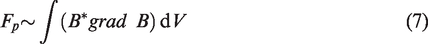
“Supra-Trans II” is one of the demonstrators for large-scale applications in the transport system, which is a research work of IFW-Dresden in cooperation with evico GmbH and other partners. This transport model was inaugurated in 2011 and allows an investigation of linear motion of the bearing system for passenger or cargo transport (Figure 12(a)).
40
,
41
In the framework of “SupraMotion 2013–2016,” the huge potential for industrial applications of SMBs is further showcased for various technologies in the field of handling, automation, etc.
42
Figure 12(b) demonstrates an X/Y table for moving objects in the X and Y directions. This enables the two slides to move and hover over the magnetic rails, which is another example of contactless movement. The smooth stainless system is easy to clean, which can be useful where cleanability is required, such as in the food, chemical or pharmaceutical industries. The other potential designs of SMBs are SupraLinearMotion (for passenger hovers without friction or noise), SupraShuttle (movement of an object in all spatial directions), SupraChanger (contactless rotary motion with very little energy, for example in the case of centrifuges or mixers), SupraCarrier (for moving glass, wood, etc., in a clean environment), etc.
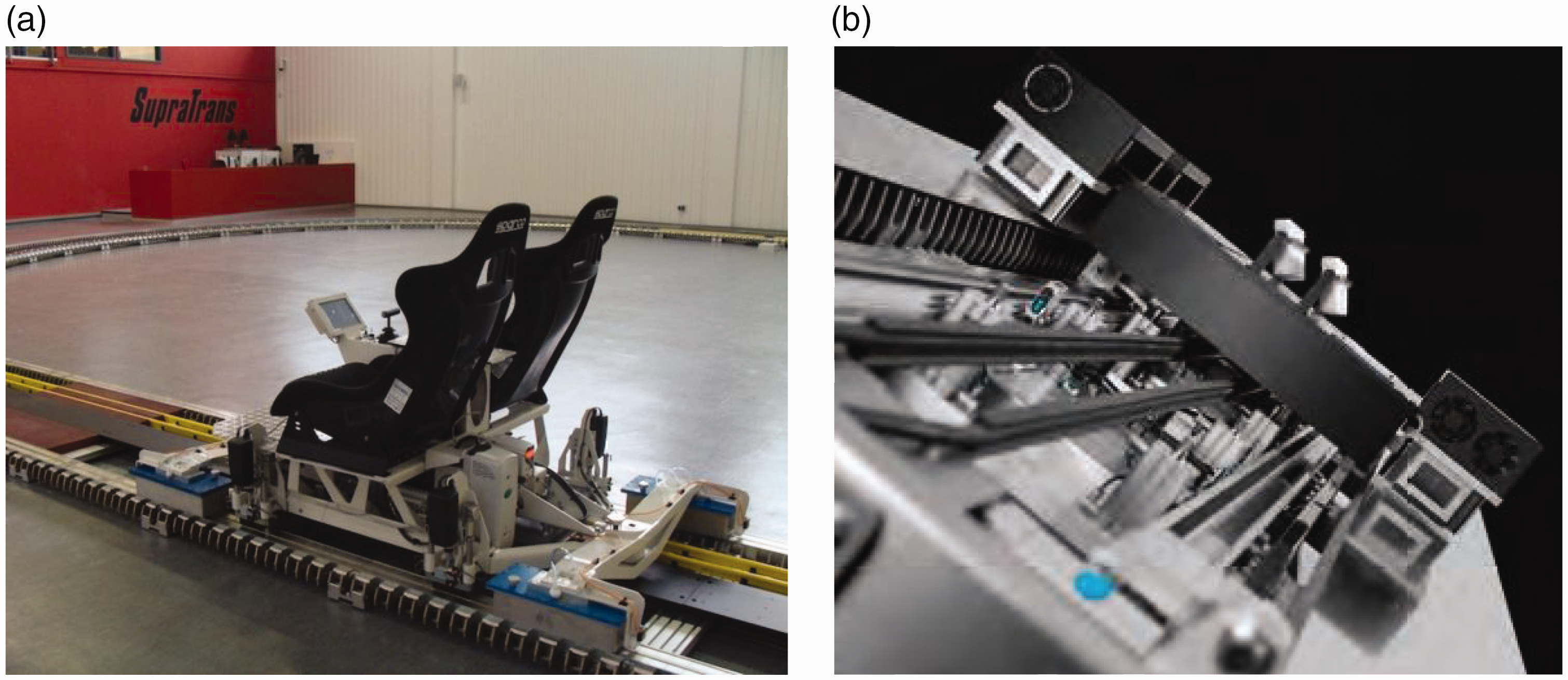
To construct a SMB, a PM is placed parallel to a superconductor with a defined air gap distance (by means of non-ferromagnetic spacers or position holders). By cooling the YBCO in the magnetic field to –196°C, for example, with LN2, the superconductor generates a restoring force due to the induced super-currents, which keep the magnet in a stable levitated position as long as the superconductor stays below its transition temperature. When the spacer is removed from this system, the PM ring levitates over the superconductor. The restoring force ensures the levitated PM ring retains its original position if the PM ring is taken away or moved due to the permanent memory effect of superconductor. The flux lines of the PM penetrating the superconductor are pinned by nano-crystalline defects within the superconductor, according to the “flux pinning effect.”
Figure 13(a) illustrates the magnetic flux lines of a PM, which are emerging from north pole to the south pole. Some of the flux lines penetrating through the superconductor are pinned by nano-crystalline defects within the superconductor, the so-called “pinning centers.” The functional principle of the bearing system is presented with the help of a flow diagram in Figure 13(b).
Superconducting bearing: (a) levitated permanent magnet above a high-temperature superconductor and (b) functional principle of superconducting magnetic bearing. 41
The use of superconducting technology in textile machines is a promising and challenging effort. The circular SMB can be used as a twisting element in place of the frictional ring/traveler twisting system in the ring spinning machine. This SMB twisting element has the following advantages over existing ring/traveler systems.
The SMB can hold objects in a stable levitated position. Thus, the SMB can be used as an alternative to expensive active electromagnetic bearings. The construction of this type of bearing is simple, compared to active magnetic bearing systems. No additional, complicated measurement or control technology is required, unlike in active magnetic bearings. No optimization is necessary during rotation of the PM ring. The SMB is suitable for larger loads due to its definable hover gap. The frictionless SMB prevents wear, lubricant residues and dust, and enables wear-free and low-maintenance operation.
Implementation of the SMB system as a twisting element in ring spinning
In order to eliminate the friction between the ring and traveler, the ITM, Technical University of Dresden (TU Dresden), and the Leibniz-Institute for Solid State and Materials Research (IFW Dresden) performed detailed investigations on a friction-free SMB twisting system in the ring spinning process, which was patented by ITM and Leibniz IFW Dresden.48–50 The aims of this finished project were theoretical and experimental investigations considering the quasi-stationary states for the development of a SMB twisting system in ring spinning machines.51–55 Therefore, a basic ring spinning tester was modified with respect to its control and driving system to realize an angular spindle speed of up to 50,000 rpm, where afterwards an innovative SMB twisting system was integrated and further experimentally investigated.
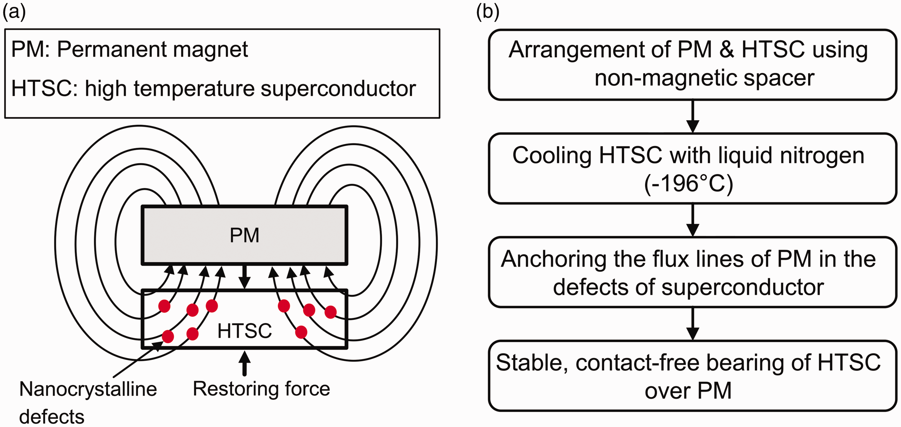
As shown in Figure 14, the ring/traveler system is replaced by a suitable design of SMB system. The PM ring (rotor) and the superconducting ring (stator) are arranged coaxially with respect to the spindle axis. The PM ring is levitated and free to rotate, while the superconductor ring remains stationary. The flux lines of the PM (rotor) penetrate the superconducting material of the stator. Before cooling, the stator and rotor are held at a fixed axial distance. After the superconductor ring is cooled below the transition temperature of the superconducting material, the PM keeps a stable levitated position, due to the principle of the “flux pinning effect.”
Schematic diagram of the ring/traveler and superconducting magnetic bearing (SMB) twisting system in ring spinning. 52
The SMB system is integrated on the right-hand side of a high-performance ring-spinning tester (Figure 15(a)). At the beginning of the spinning process, a PM made of neodymium iron boron (NdFeB) is coaxially placed over the bath cryostat with non-magnetic spacers to fix the levitation distance between the PM ring and the superconductor YBCO, located in the bath cryostat (Figure 15(b)). Subsequently, the superconductor is cooled down with LN2 supplied from a dewar below its superconducting transition temperature Tc = 91 K.
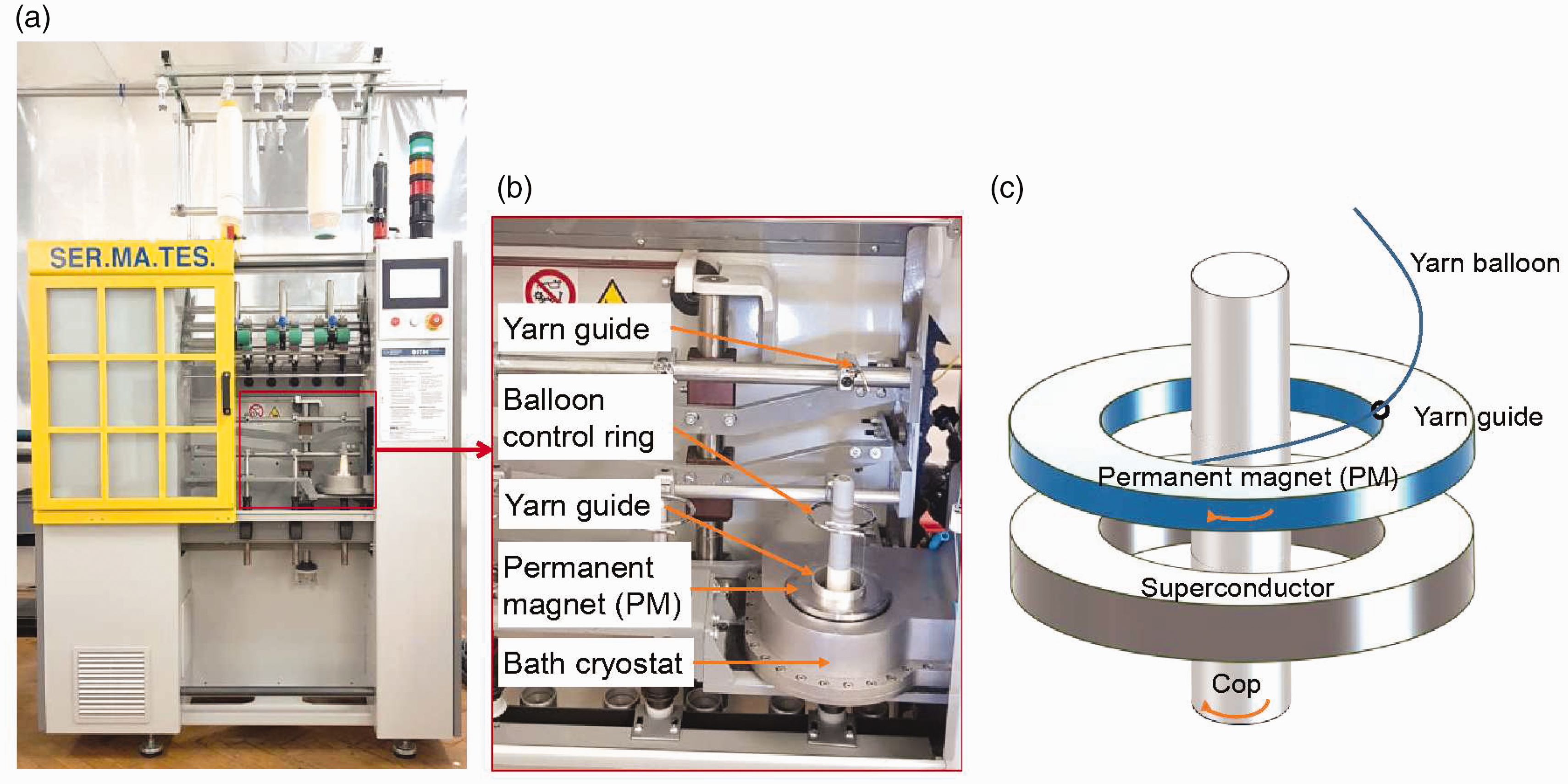
(a) Superconducting high-performance ring spinning tester. (b) Superconducting magnetic bearing (SMB) twisting system with a bath cryostat and (c) Principle of the SMB system. 57
In the superconducting state, the PM ring levitates and can freely rotate even up to an angular speed of 50,000 rpm (Figure 15(c)). During spinning, the yarn is guided through a yarn guiding system mounted on the PM ring, which replaces the classic traveler. Moreover, the PM ring is dragged with the rotating spindle via the yarn attached to it. The difference in speed between the spindle and the PM ring results in yarn being wound onto the cops.
The dynamic yarn path considering the resultant forces after replacing the ring/traveler system with the SMB twisting element were theoretically modeled and numerically solved with the Runge–Kutta method using a MATLAB program for a quasi-stationary state with different parameters, such as spindle speeds up to 50,000 rpm, yarn count, balloon control ring, yarn elasticity, balloon geometry, etc.56–58 Simultaneously, the SMB was modeled as a simple spring-mass-damper system. It was found that this description is not sufficient as the experiments showed that in contrast to classical harmonic damped oscillation systems, the decay constant δ of the free oscillation in the SMB was dependent on the original deflection. 60 , 61 As the vibration in the yarn influences the yarn tension, a new approach about the natural oscillations of yarn balloons was developed in cooperation with the Institute of Solid Mechanics, Chair of Dynamics and Mechanism Design (IFKM), TU Dresden. 62 Moreover, in situ measuring systems were developed to measure the yarn tension distribution and balloon form along the dynamic yarn path.57,63 Furthermore, comparative studies on the yarn properties utilizing the ring/traveler and SMB twisting system were carried out and analyzed using the analysis of variance (ANOVA) method. 62
The intensive researches show that the friction-free SMB system can be an alternative to replace the existing twisting system and to alleviate the crucial frictional heat. It is expected to at least double the speed of the ring spinning machine, as there is no friction in the SMB system during operation. Thus, the SMB can revolutionize the twisting principle in textile technology and can eliminate the friction of the ring/traveler systems.
Concepts of reducing yarn tension
Typically, the balloon control ring is used in the ring spinning machine to reduce the yarn tension to some extent, which was already investigated, to determine its different parameters, such as optimal diameter or the position between the yarn guide and ring/traveler system. 64 The other approaches of reducing yarn tension deal with different forms of balloon control rings or implementing new concepts, or even replacing the current ring/traveler system. Further approaches involve implementing a multi-balloon system by increasing the balloon height, which should decrease the yarn tension according to the theoretical model described in the literature.64,65
Cap spinning device
To spin yarn at higher rotational speeds, it is important to consider the air-drag force, which acts against the rotating balloon, causing higher yarn tension and eventually end-breakages. Therefore, a cap-shaped balloon control ring (1) has been constructed, which rotates to impart twist. 66 In this case, the conical diverging formed cap (1) replaces the balloon control ring and the ring/traveler system. As illustrated in Figure 16, the cap spinning device comprises a cap (1) and a drivable spindle (3), and the cap (1) is dragged by the thread (15). An attachment (8) with an angled thread guide (10) is rotatable coaxially with the spindle and guiding the thread (15) to the rotational axis (2). According to the principle of cap spinning, the thread (15) coming from drafting rollers (17) passes through the thread eyelet (18) and the inlet passage (10), which guides the thread (15) into the rotation axis (2). The thread (15) exits through an opening (19) in the cap (1) located below the bearing (12). After wrapping around the thread (15) on the outer surface of the cap (1), the thread passes through a guide eye (20) located in the lower edge of the cap (1) and is wound onto the tube (4) to form the cop’s package (6). Here, the yarn tension is independent of the actual spindle speed during its synchronous running, which allows an increase of the spindle speed. However, the driving system of the balloon control ring cannot run with the actual mechanical bearing at higher speed, which causes extremely high energy costs.
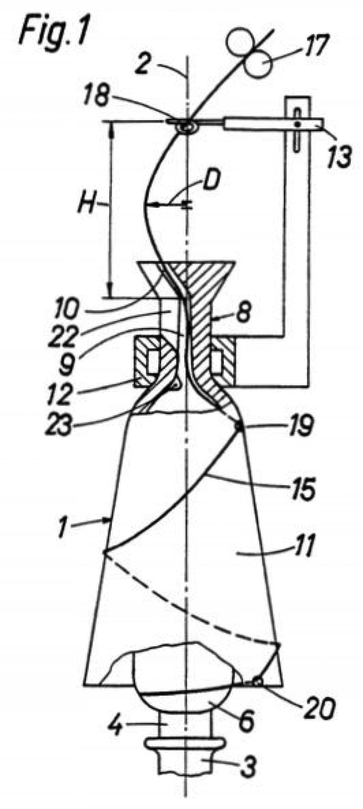
Cap spinning device. 66 1: cap; 2: rotational axis; 3: spindle; 4: tube; 15: thread; 17: drafting rollers; 19/20: thread eye.
Loop spinning
In the loop spinning or twisting of thread, free rotating loops are controlled by a balloon-limiting mechanism (or by a rotating sleeve). A rotating sleeve has been designed to replace the conventional ring–traveler system, which is named loop spinning.67,68 As shown in Figure 17, the yarn (P) coming from the feed rollers (1) during operation and guided by the guiding roller (19) enters the opening (18) of the tubular rotating sleeve (9), which is arranged coaxially to the spindle (2) and acts as a balloon limiter. Moreover, the rotational speed of the sleeve (9) is higher than that of the spindle (2). The resultant yarn balloon (6) touches the inner surface (10) and moves towards the lower end (11) of the rotating sleeve (9). The yarn (P) goes outside from the axis (A) of the spindle (2) and forms a rotating open yarn loop (23) due to the centrifugal force. Finally, the yarn (P) is wound onto the tube (3) to form the yarn package (4).
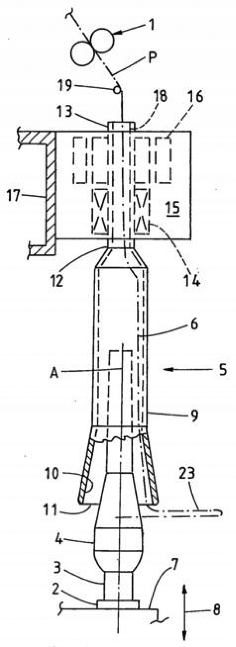
Loop spinning. 67 P: yarn; 1: feed rollers; 2: spindle; 3: tube; 4: yarn package; 9: rotating sleeve; 23: open yarn loop.
Nova spinning system. 69
Nova spinning system
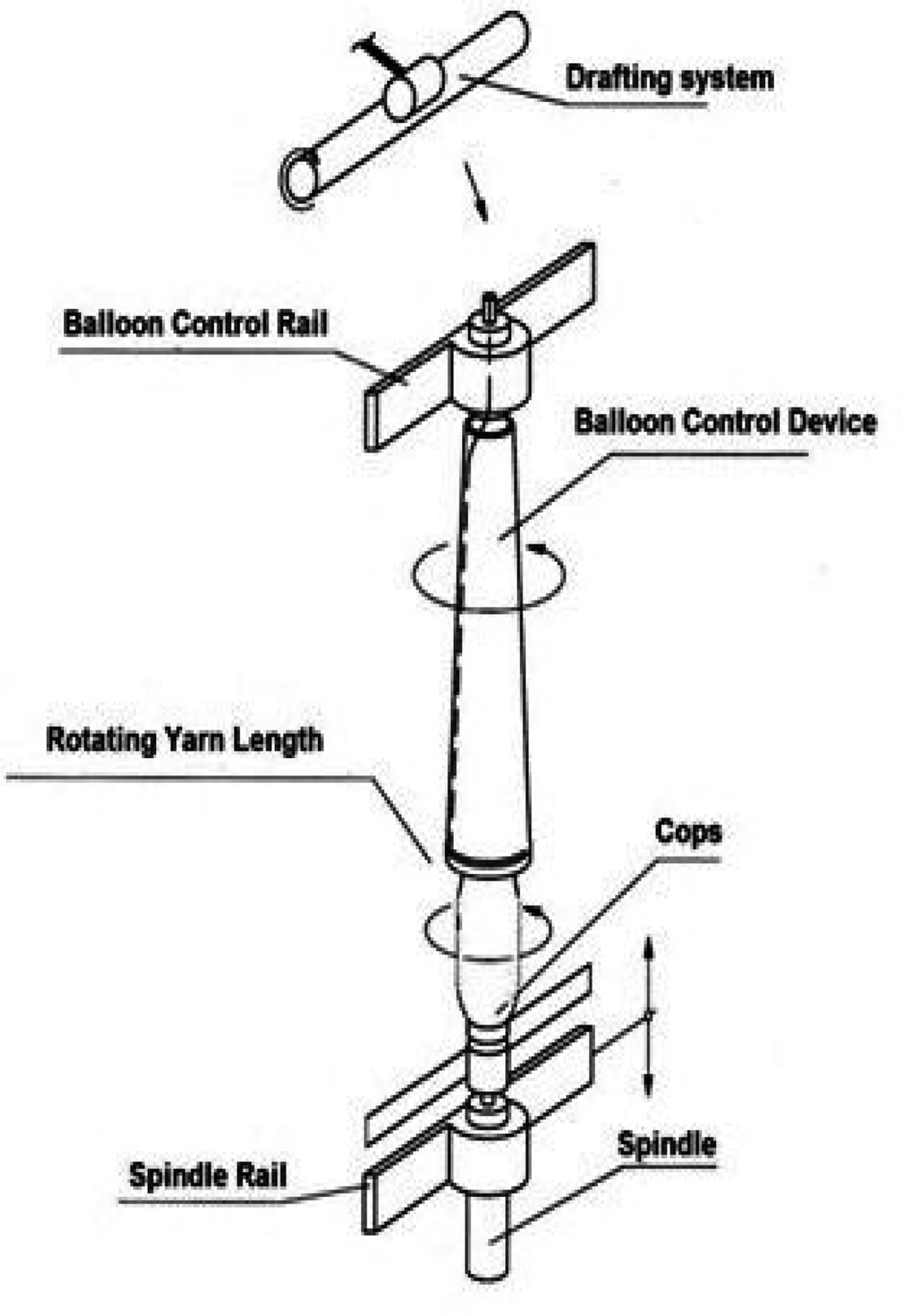
In this system, the spindle is mounted on a spindle rail, which is vertically movable in order to build the layer of yarn on the cops. This means that the yarn length between the drafting system and winding point of the cops remains constant and independent from the height of the balloon control device and the spindle. As shown in the Figure 18, the telescopic balloon control device is fixed at the balloon control rail. Due to its rotation, twist is inserted in the yarn. The spindle and balloon control device rotate in the same direction. The speed difference between them helps to wind yarn on the bobbin. With this spinning system, this spindle speed can be increased up to 50,000 rpm to produce yarn from 5–50 tex. 69 It is also estimated to save costs of up to 25% in comparison to the conventional ring spinning process.
Multi-balloon (or Spinhole) technology
Spinhole technology is a new technology based on a self-harmonically controlled multi-balloon system that eliminates the high balloon tension that occurs during twisting of yarn of the balloon in the ring spinning process. This system allows one to use lighter travelers without any use of balloon control ring to increase the angular spindle speed up to 30,000–35,000 rpm using the existing ring/traveler system and produces a comparable yarn quality. Figure 19 illustrates a comparison of the balloon form considering the conventional and Spinhole ring spinning processes, where the multi-balloons are formed by increasing the balloon height, that is, the distance between yarn guide and ring/traveler system, to 250–900 mm. 77
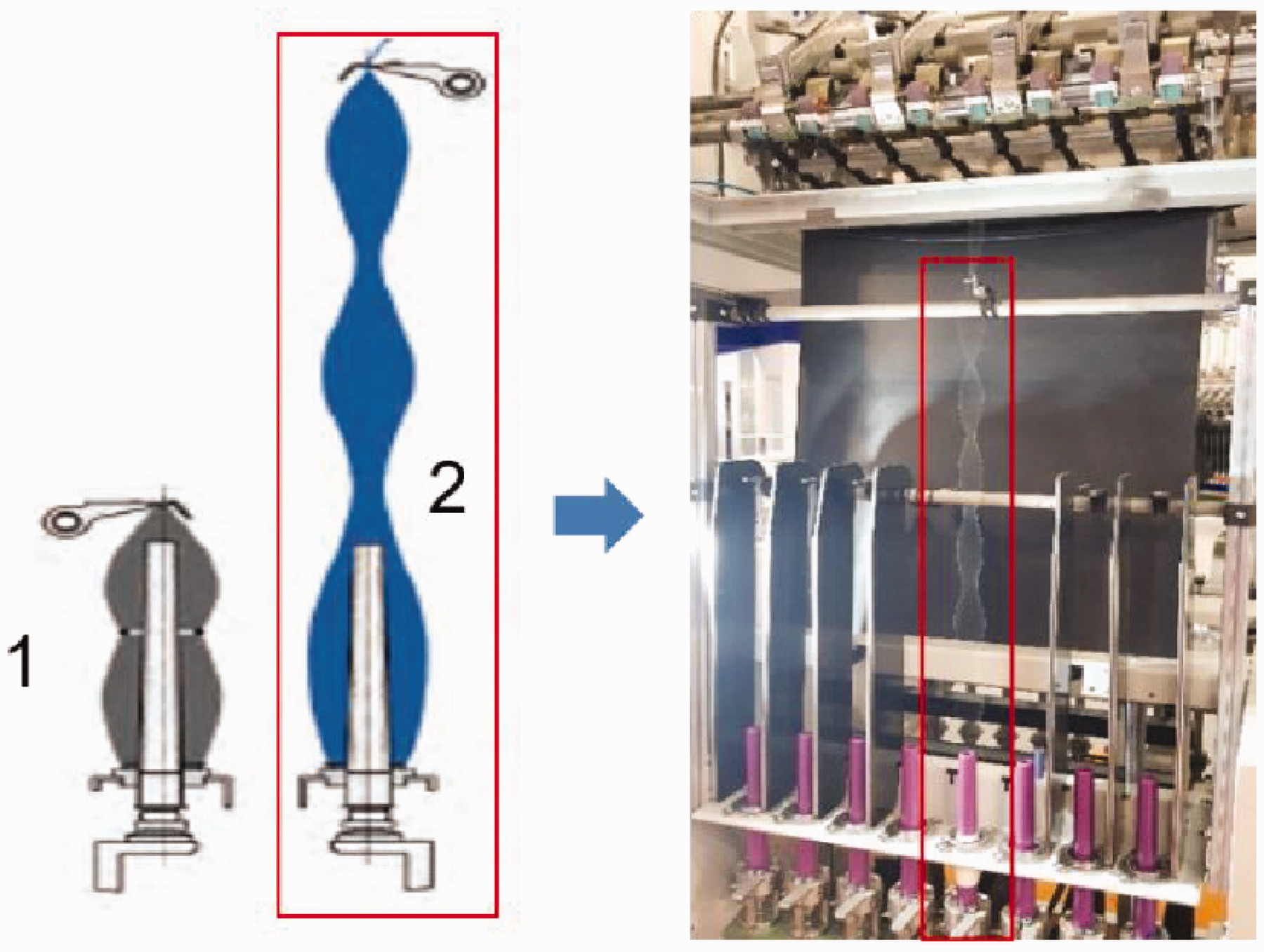
Multiple balloon/Spinhole® system. 70 1: standard balloon; 2: multi-balloon system.
Adding a false twisting device
In the ring spinning process, the yarn twist is generated through the rotation of the ring/traveler twisting element, which propagates along the yarn path between delivery rollers and cops. A change in the level of twist affects the process, yarn tension, yarn breakage rate and yarn properties. This is why a false twisting device was added to impart false twist in the spinning triangle zone, that is, in the weakest point of the yarn path located immediately after the front rollers of the drafting system, to increase process stability and yarn quality.71–83
Yilmaz has studied the characteristic properties of the yarn by integrating a false twisting device comprised of air nozzles between the drafting system and yarn guide to reduce the yarn hairiness up to an angular spindle speed of 10,000 rpm in the conventional ring spinning process (Figure 20). 71 The objective of integrating the pre-twisting device was to bind the projected fibers onto the yarn body by the swirling airflow in the nozzle. However, the wrapping motion of the airflow is insufficient to produce stronger yarns compared to conventional ring yarns. Liu et al. 73 , 74 and Wang et al. 75 designed a false twisting device with a controlled high-pressure vortex airflow on the lower side of the delivery rollers of the drafting system in order to influence the twisting propagation along the yarn path to improve the spun yarn qualities in the conventional ring spinning system (Figure 21). Thus, the pre-twisting effect is transferred to the nip of the delivery rollers together with the normal twist produced by the rotation of the main twisting element, that is, the ring/traveler system. However, the analysis was carried out only up to an angular spindle speed of 14,000 rpm considering the fine yarn count, as the yarn quality degraded using a medium yarn count due to the strong airflow. Wang et al. 75 further described a model by adding a pre-twister to produce pneumatically entangled real twists with air nozzles on the fine strand prior to the twisting by the ring/traveler system. However, the experiment was carried out up to an angular spindle speed of 10,000 rpm for 100% cotton materials only, as the yarn quality was also deteriorated using the pre-twister.
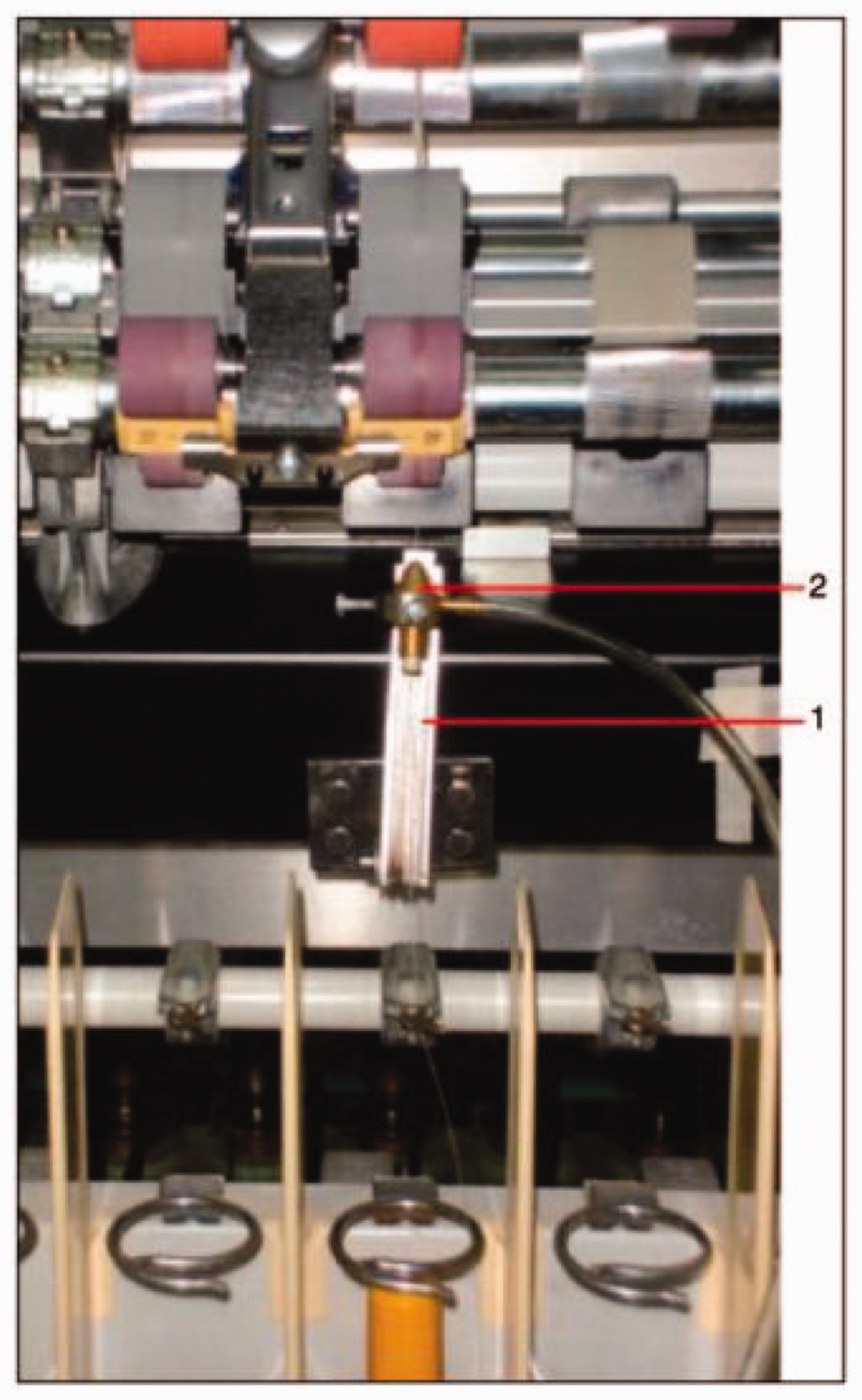
Air nozzle integrated in the ring spinning machine. 71 1: supporting device; 2: air nozzle.
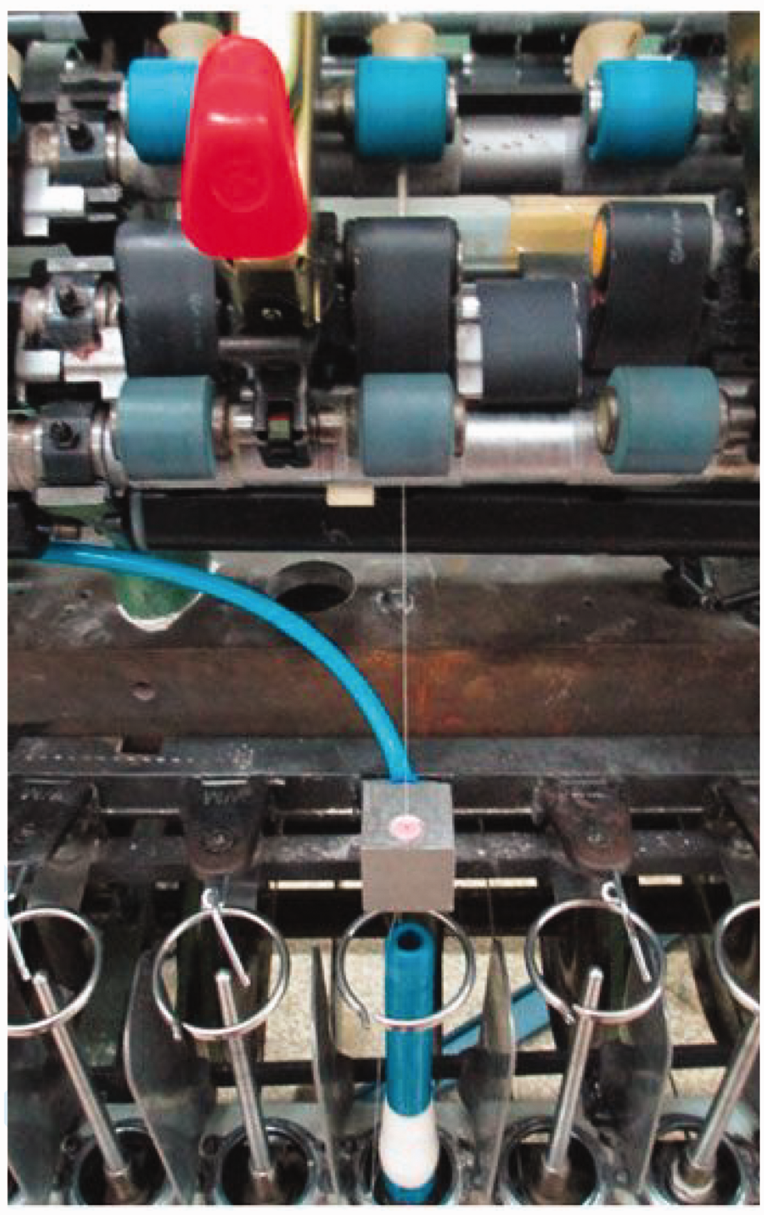
False twisting device integrated between the yarn guide and balloon control ring. 73
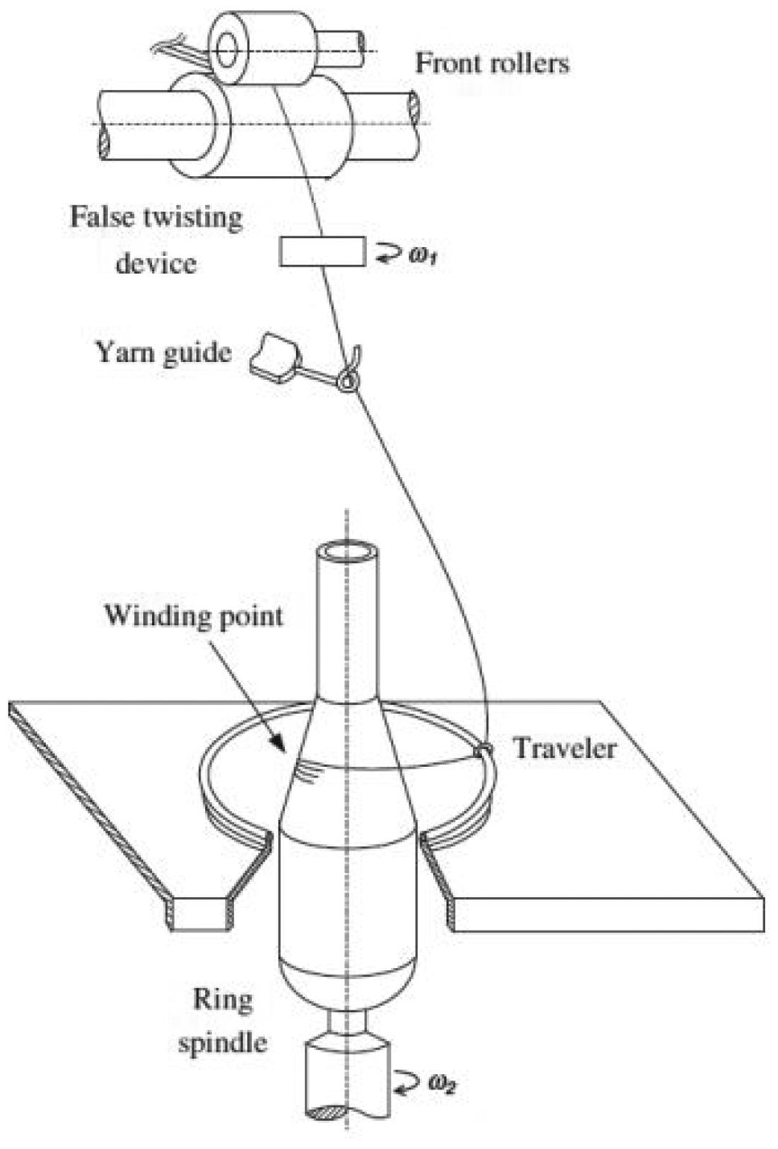
A further false twisting method deals with the Nu-Torque technology based on one or two separate false twisting devices positioned between the yarn guide and delivery rollers of the drafting system in the conventional ring spinning process in order to reduce the residual torque in the yarn.76–84 As illustrated in Figure 22, the drafted roving passes through the two twisting elements, that is, the false twisting device and the ring/traveler system rotating in the same direction, to impart twist in the yarn. The preliminary single yarn is generated through the rotation of the false twister, which is untwisted just after leaving the false twister and, finally, the real twist is imparted in the yarn through the ring/traveler twisting element. 79
The spun yarn (6–100 Ne) possesses 10–40% reduced twist, but the same or higher yarn strength, lower yarn hairiness and better yarn evenness compared to the ring spun yarn.78,79 Moreover, the low torque ring spun yarn is compacter than that of conventional ring spun yarn. 81 Thus, the Nu-Torque technology, particularly in the compact ring spinning process, can produce high-quality yarns and fine count yarns with reduced neps, thick and thin places, etc. 77 It also helps to save the energy of up to 18–40% in the ring spinning process. 84
Compact spinning
In the drafting system of the ring spinning machine, if the total draft (break draft/main draft) is high, the edge fibers break, especially in the spinning triangle zone, as illustrated schematically in Figure 23, and produce hairy yarn. Rieter has developed a compacting device (ComforSpin) to laterally condense the fiber with an air-guiding element with suction between the drafting unit and spinning triangle, so that the width of the spindle triangle (b) can be narrowed, so that edge fibers can be integrated in the yarn structure (Figures 24 and 25). Thus, it is possible to produce high-quality compact ring yarn with lower hairiness as well as higher strength and elongation in comparison to conventional ring yarn. EliTe (Spindlefabrik Suessen), Air-Com-Tex700 (Zinser Textilmaschinen GmbH), etc., are the other examples of compacting devices with a modification in the front of the drafting system. 85 The productivity can be thus increased by 10–15%.
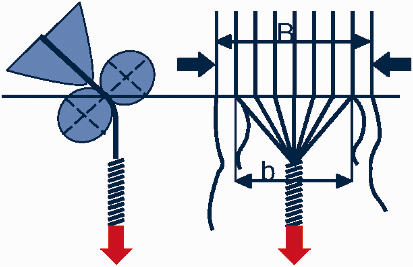
Spinning triangle in conventional spinning. 3
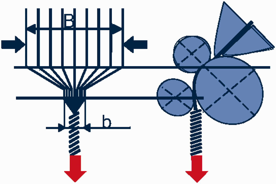
Spinning triangle in compact spinning. 3
Compacting zone with an air guide element. 3
Other developments
Other development concerns a modular high-speed ring spinning tester developed and introduced by Toyota Industries Corporation at ITMA 2019, where a twisting system similar to that of a pot spinning process was exploited. The twisting process was done by using a rotating drum, where the twisted yarn was accumulated in the inner surface of the drum. Afterwards, a cop was inserted separately to collect the twisted yarn onto it. Although Toyota claimed to increase the spindle speed up to 50,000 rpm, no detailed information was disclosed about this technology. Moreover, the accumulated twisted yarn on the drum could not be retained with accurate yarn layers on the cop, which can impede further textile processing, such as an unwinding process of the yarn.
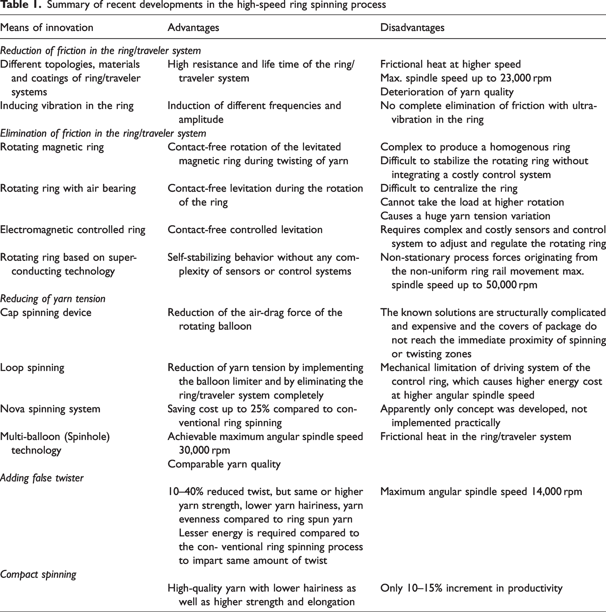
All of the above-mentioned developments are summarized in Table 1.
Summary of recent developments in the high-speed ring spinning process
Conclusion and outlook
The present paper summarizes the recent developments of ring spinning processes in terms of productivity, especially considering their practical implementation. The literature review shows that the currently existing ring/traveler twisting system still dominates in the ring spinning process by using improved coatings and material, so that the wear of the system can be reduced. The compact spinning process utilizes the compacting device to narrow the spinning triangle in front of the drafting zone and produces high-quality yarn, especially with low hairiness. Adding a false twisting device to the existing ring/traveler system to impart additional twist in the spinning triangle helps to increase the process stability, as most of the yarn breakages occurs in the spinning triangle zone due to the low twist distribution along the yarn path. In the Nu-Torque technology based on the false twisting device, many researches were conducted to produce yarn with reduced twist but the same or higher yarn strength in comparison to conventional ring spun yarn. Reduction of twist helps to save energy, but the maximum spindle speed was reported as 14,000 rpm. As the fundamental limitation, that is, friction between ring and traveler still exists, the development helps to some extent to increase productivity by up to 10–15%. Recently, multi-balloon (Spinhole) technology was implemented by increasing the balloon height by three to four times to reduce the yarn tension and thus to increase the speed up to 35,000 rpm, even using the existing ring/traveler system.
To eliminate the frictional problem in the current ring/traveler system, the implementation of the ring levitated by air pressure or magnetic force based on the levitation principle is one of the most promising inventions to replace the ring/traveler system to increase productivity. However, it is complicated to control the rotating ring at higher speeds. Most of the ideas with rotating rings have not been implemented in the real spinning process. On the other hand, the implementation of the SMB system offers friction-free twisting, where no sensor or complex control system is needed during its rotation to impart twist in the ring spinning process. The functionality of the integrated SMB system has already been investigated up to an angular spindle speed of 35,000 rpm. Further researches will be carried out particularly on the non-stationary yarn dynamics in interaction with the SMB system during the high-speed ring spinning process.
Thus, the results of the presented work reveal the enormous potential of the innovative twisting mechanism, so that the productivity of ring spinning can be even doubled for the first time in 100 years.
Footnotes
Declaration of conflicting interests
The author(s) declared no potential conflicts of interest with respect to the research, authorship, and/or publication of this article.
Funding
The author(s) disclosed receipt of the following financial support for the research, authorship, and/or publication of this article: This work was supported by the research program of the German Research Foundation, DFG – 459466327 (Project-CH 174/61-1) at the Technische Universität Dresden, Germany.