
Abstract
In the textile sector, the sustainable development and production of high-performance and high-quality textiles has become increasingly important. To enable the processing of new yarn materials at high production speeds, the in-depth understanding of the relationships between machine elements, yarn path, and yarn tension is required. Therefore, the aim of this paper is to analyze the interactions between the warp knitting machine unit and the yarn path during the stitch formation process by means of theoretical modeling and experimental investigation. A vector-based model has been developed to describe the kinematic yarn path and its correlation with yarn demand during the stitch formation process. The model is validated by measurements of yarn path and yarn tension on a warp knitting machine. The model is used to identify both machine and yarn guide elements that influence stitch formation.
The textile industry is increasingly demanding sustainable solutions to improve the production and product changes, taking into account the diversity of fabric material requirements. High performance and equally sustainable yarn materials (e.g. high tenacity filament yarns or staple fiber yarns) require adaptation of machine settings and modification of yarn guiding elements. Therefore, especially in the case of warp knitting, there is a great interest in investigating the stitch formation process and its interactions with and dependencies on yarn guide elements. Furthermore, the complexity of textile manufacturing processes makes it difficult to establish relationships between machine-specific and technological parameters. In order to improve production efficiency and quality, it is necessary to carry out in-depth analyses of textile production. The modeling of the textile machinery is an appropriate tool to investigate the relationships between yarn material and processing procedures.
Previous research projects have looked at different modeling approaches for textile operations involving the processing of yarns, such as weaving, weft knitting, and warp knitting. For weaving, extensive research efforts have been devoted to the mathematical description of processes and products. For example, De Weldige 1 evaluated warp yarn tensions occurring during the weaving process in the context of machine and product parameters. The author described the yarn sheet based on a linear-elastic spring behavior in addition to being flexible and massless. However, the aspect of friction between yarns and machine elements was not included in the study. In 1998, Chen 2 adopted a similar approach and added models suitable for describing both individual yarns and warp yarn sheets. Moreover, the shed geometry of the weaving machine and machine dynamics were integral parts of the research. In a later study, Wolters 3 generated neural networks based on the work of De Weldige, which helped to create reference force flows taking into account products, yarns, and machine parameters. Beitelschmidt 4 described the behavior of warp yarns under dynamic stress using a mass flow model to characterize yarn motion. The author’s research efforts included longitudinal dynamics in the interaction of mass and elastic properties of pretensioned yarns. Finckh 5 simulated a fabric manufacturing process using numerical micromodels; yarns were described as beam elements while the study included a contact definition between individual filaments and yarns as well as weft beat-up and heddle motion. Another publication by Gloy et al. 6 presented a generic approach to determine the influence of the back rest, heald frame, and reed motion on the yarn path, also including the yarn elasticity factor. De Meulemeester et al. 7 used the finite volume method to simulate the weft insertion for air-jet weaving machines. In that investigation, the yarn was divided into discrete elements to which Newton’s second law was applied and which were connected by elastic coupling. Vilfayeau et al. 8 described the yarn as a three-dimensional (3D) continuum with transversely isotropic behavior, taking into account the effects of yarn friction, reed motion, and weft insertion. In contrast, Zhou et al. 9 used so-called multichain digital elements to characterize woven textile fabrics because of their ability to represent the influence of friction between yarns. However, the effects resulting from the weaving process were neglected in that study. To fill this gap, the present study focused on the weaving process.
Research projects have also been carried out to characterize and model processes and textiles in terms of stitch formation procedures, for example, knitting and warp knitting were carried out likewise. Koo 10 evaluated the yarn tension in circular knitting for different needle gauges and shapes. Duru et al. 11 presented metrological investigations of the resistance of the knitting needle during the process. De Vasconcelos et al. 12 specified the influence of tension on stitch length using circular knitting as an example. That approach included a mathematical evaluation of the yarn path. Based on a simulation model, Matthes and colleagues13,14 described the yarn path for circular knitting machines. All subsystems, for example, bobbin, feeder, and knitting needle, were analyzed in detail, and the corresponding influencing factors were derived.
With a focus on fabrics produced on a warp knitting machine, a 3D simulation of stitches using nonuniform B-splines was performed by Goktepe 15 in 2002 and Honglian and Harlock 16 in 2009. Renkens and Kyosev17,18 also tackled the challenging task of the 3D simulation of warp knitted fabrics. The authors performed a vector-based simulation of the stitch geometry. However, these models for warp knitted fabrics neglected the influence of machine elements on the stitch formation process itself. Metzkes et al. 19 and Märtin 20 described the yarn path for warp knitting machines based on Ritz discretization. The basic parameters chosen were the yarn characteristics and the dynamics of the system due to guide bar motions. The yarn was considered as a one-dimensional continuum, and the corresponding calculations were based on the string or elongation bar theory. This model included the dynamic movement of yarns between the tension compensator and the warp knitting area, focusing on how the movement of the guide needle affected the yarn path. Between the guide needle and the knock-over edge, the center of mass of the yarn was assumed to be at the knock-over edge. The yarn path was assumed to be straight. However, the motion of the yarns against the knock-over edge was not included, so that the effects of warp knitting motion and stitch formation itself were missing from the model. As a result, that approach provides only an approximate description of the yarn path in the warp knitting machines.
Liu and Miao 21 presented a mathematical calculation of yarn consumption for warp knitting machines in their paper. Both the movement of the guide bars and the movement of the needles were considered. The tension compensator, which compensates the free yarn lengths during the process, was assumed to be in a fixed position. The stitch formation process was divided into four sections, that is, underlap, swing through, overlap and swing back. This approach showed that a reduction and homogenization of yarn tension is required to improve the performance of warp knitting machines and the quality of knitted fabrics. Liu et al. 22 have recently developed a stitch modeling and simulation for 3D warp knitted tubes. In that paper, stitches were deformed according to the principle of the mass-spring model so as to make the mesh structure appear. However, the movement of all the stitch-forming machine elements, which is an essential factor for the yarn path, was not considered. This is necessary for a thorough understanding of the relationships between machine elements, yarn path, and yarn tension. Therefore, the research presented in this paper aims at an analytical description of the stitch formation process in a warp knitting machine, in addition to the metrological investigation of the yarn motion.
Materials and methods
Analysis of the warp knitting machine
Figure 1 shows a schematic cross-sectional view of the yarn path in a Copcentra 3K warp knitting machine (Karl Mayer Holding GmbH & Co. KG). The yarns run from the warp beams (B) via yarn deflectors, yarn combs, and tension compensators (T) to the machine elements where the stitch formation takes place. The guide needles on the guide bar (G) guide the yarn around the compound needle (N) in order to enable stitch formation. The stitches are joined to the warp knit fabric by the knock-over/holding-down sinker (S), the sliding closing wire (C) and the needle bar (N). The warp knit fabric produced is fed to the take-down unit (D) and is stored on a fabric beam.
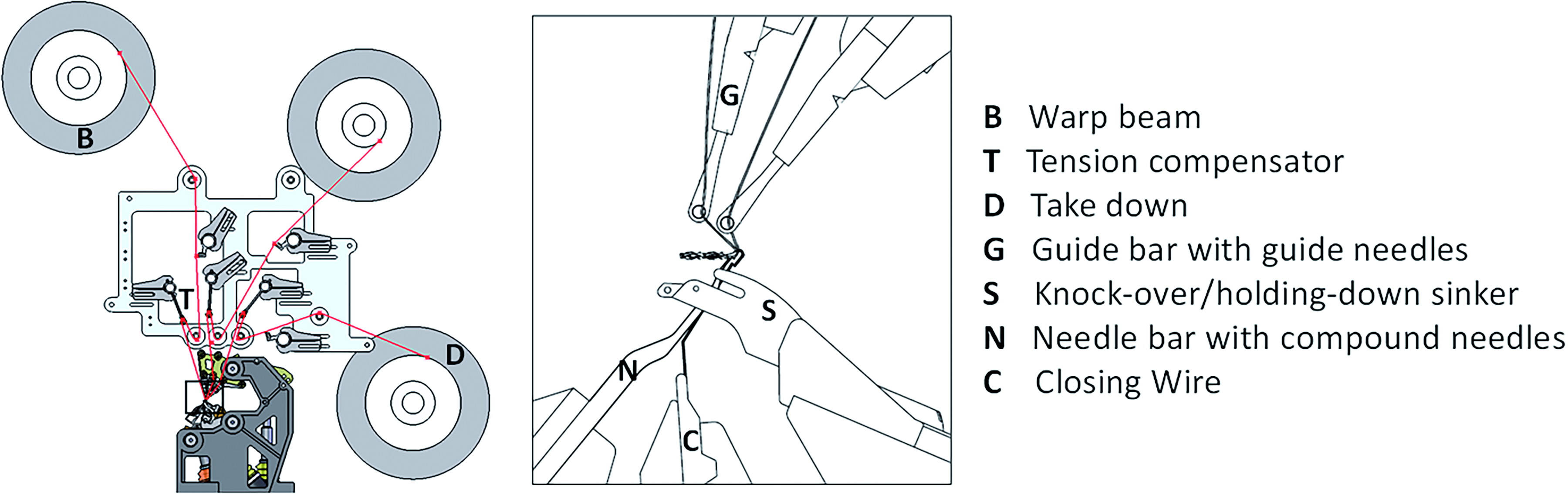
Simplified yarn path in the warp knitting machine (cross-sectional view).
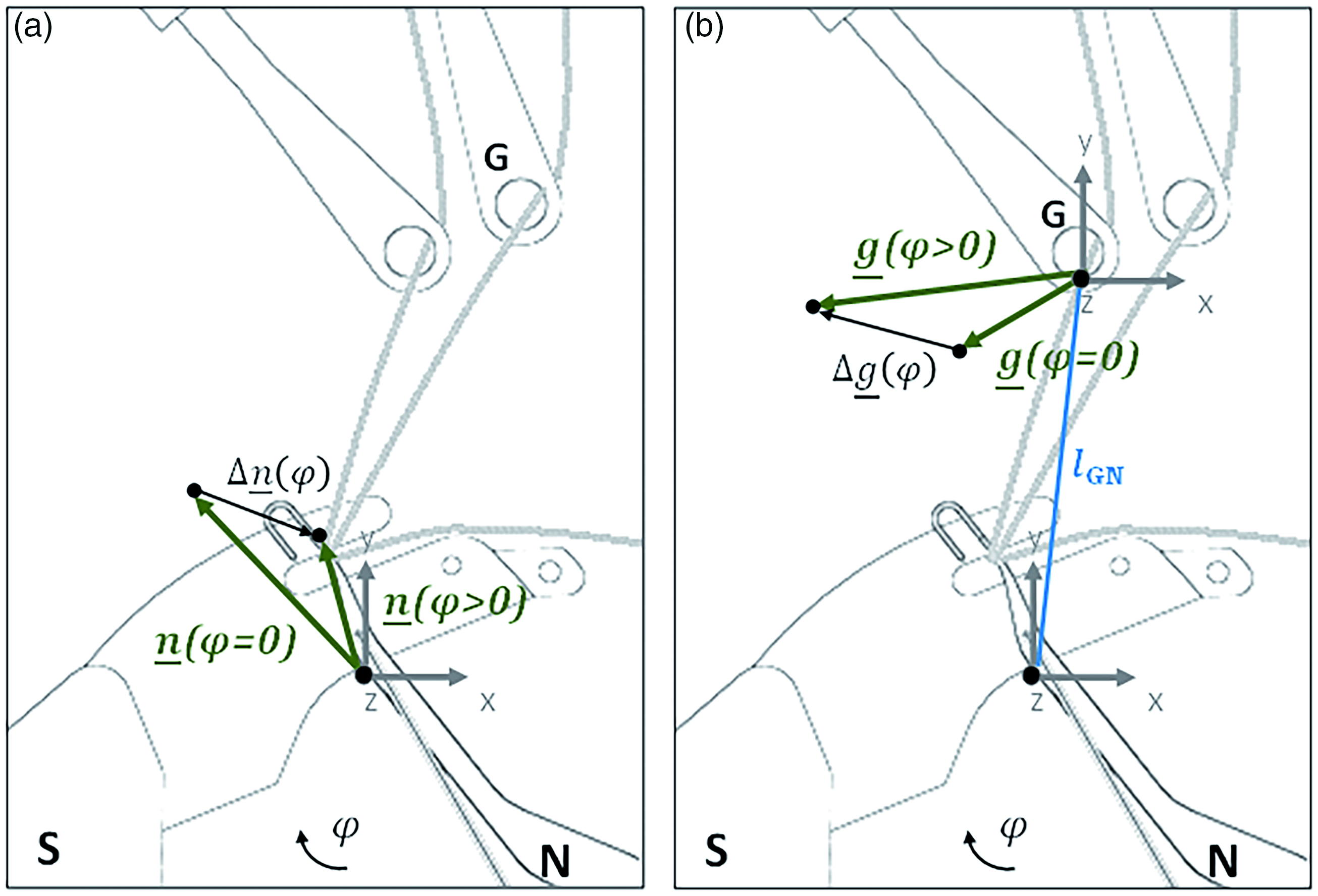
Sketch containing the notation of motion coordinates in the warp knitting machine: (a) compound needle and (b) guide needle.
The yarn feed from the warp beam to the take-down unit is controlled at a constant speed. However, yarn consumption is inhomogeneous due to the superimposed movements of the warp knitting machine elements during the stitch formation process. The guide bars (G), including their attached guide needles, then perform a swing and offset movement subsequently. The movement of the guide bars in relation to the needle bar is divided into the sections underlapping, swinging in, overlapping, and swinging out. The sinker (S) moves down to the knock-over position. The compound needle (N) moves up to the yarn laying position and down to the knock-over position. The movement of the closing wire (C) causes the compound needle to open and close. In the stitch formation area, yarn consumption is highly discontinuous (even negative) due to the guide needles swinging around the compound needles. This creates different yarn speeds and accelerations during the process, resulting in oscillations, varying tensions, and inhomogeneous yarn tensions within the yarn sheet. This discontinuity is exacerbated by the stitch formation itself in the lower area of the needle’s dead center.
The tension compensator (T) compensates for differences in yarn speed and yarn to homogenize yarn tensions. Most importantly, the maximum tension of the process must not exceed the breaking strength of the yarns. The tension compensators are currently designed as passive spring-mass systems. As production speed increases, the effects of mass inertia increase, and the tension compensators are stimulated in the natural frequency range. As a result, tension compensators do not respond proportionally to changes in yarn speed. As the yarn speed increases, their oscillation increases. This is an obstacle to the desired stable compensation of length differences. When processing extremely elastic yarn materials, different yarn tensions occur within a yarn sheet. Therefore, a high elastic elongation of the material is required to compensate for these differences. In the case of low-elasticity yarns, both extremely high and extremely low yarn tensions (down to 0 cN) can occur due to varying tensions within a yarn sheet. If the yarn force is too low during warp knitting, it certainly tends to reach too low pretension. This can lead to irregularities in the stitch formation process, resulting in an inaccurate appearance of the warp knit fabric or yarn breakage. Extremely high yarn tensions, on the other hand, result in unwanted wear on machine elements, a significant loss of quality, and yarn breakage. To increase machine speed and fabric quality, the factors influencing yarn movement, yarn demand and yarn tension must be analyzed in detail.
Modeling of the stitch formation process
Model assumptions
As a basis for the desired model, a coordinate system is created whose reference zero points are located at the point of contact between the yarn and the compound needle at the lower dead center (mass point). The x coordinate is horizontal and at 90 degrees to the fabric width, the y coordinate is vertical, and the z coordinate is horizontal and aligned in the direction of the fabric width (guide bar offset). Any movement in the positive y direction, that is, towards the tension compensator (T), is assumed to release yarn length, thereby reducing yarn tension. Any movement in the negative y direction, that is, away from the tension compensator (T), is assumed to consume length, which in turn increases the yarn tension that must be released by the tension compensator. As the yarn moves in the direction of the take-up unit, it is expected that the start and end positions of the overall yarn motion will not coincide, resulting in the motion of the mass point in the form of an open polygonal curve.
To simplify this approach, an assumption is made as to which machine element affects the yarn motion as a function of machine rotation angle and process step. The movement of the guide needles in the z direction is included in the investigations as the yarn is guided by the guide needles. The model is based on the geometric calculation of the yarn length that is generated between the contact point of the guide needle (G) and the compound needle (N) or sinker (S). The movement of the mass point is mathematically described based on vectorial calculations for the stitch formation process during one machine revolution.
A kinematic geometric model is created without material specific values. In accordance with the focus on geometric modeling, the influence of yarn elongation on yarn demand is neglected, but can be incorporated into the model if required. As the stitch formation process is the main influence on the variation in yarn demand during the warp knitting process, the variation in yarn length between the warp beam and the tension compensator and between the tension compensator and the guide needles is neglected.
The length of yarn required during the stitch formation process depends on the position of the warp knitting machine elements and the contact points between the yarn and the machine elements (guide needle (G), compound needle (N), and sinker (S)). The positions of the elements and therefore the contact points change continuously during the course of a machine revolution. However, the coordinate system of each machine element is defined by its position. The movement coordinates of the machine elements are the input parameters for the yarn path model. They are given in the Appendix. To account for the distance between the machine elements, the distance between the origins of the coordinate systems is included in the model. The distance between the origin points of the coordinate systems of the guide needle and the sinker is defined as
The movement of the compound needle is presented in Fig. 2a and is defined as the vector
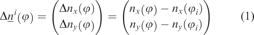
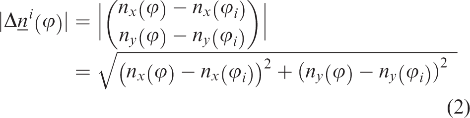
The thread path is approximated by the length of the change in motion of the machine elements. Therefore, the amount of
For the calculation of the yarn path, the definition of variables is summarized in Figure 3. The yarn is simplified to a single mass point (P, P′). For the start of stitch formation, this mass point is assumed to be at the contact point between the yarn and needle head (origin of coordinate system of N). The starting time of stitch formation and yarn motion, that is, the beginning of the first process step, is defined as to where the compound needle is at its lowest knock-over position. The starting time is defined as
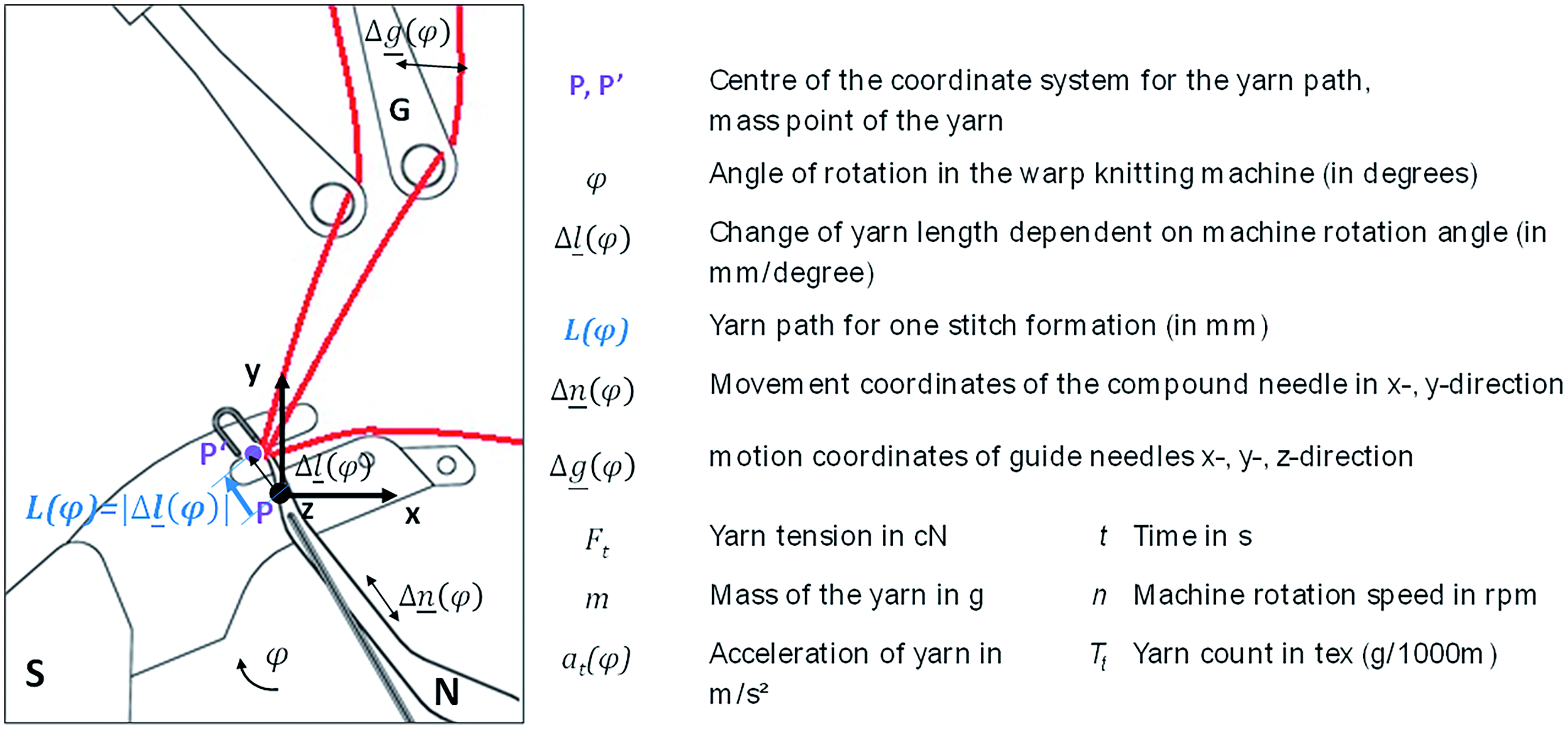
Definition of variables for the geometrical model of the yarn path L(φ) in the warp knitting machine.
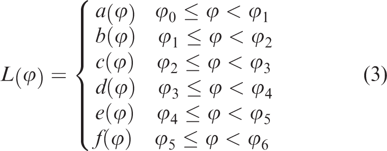
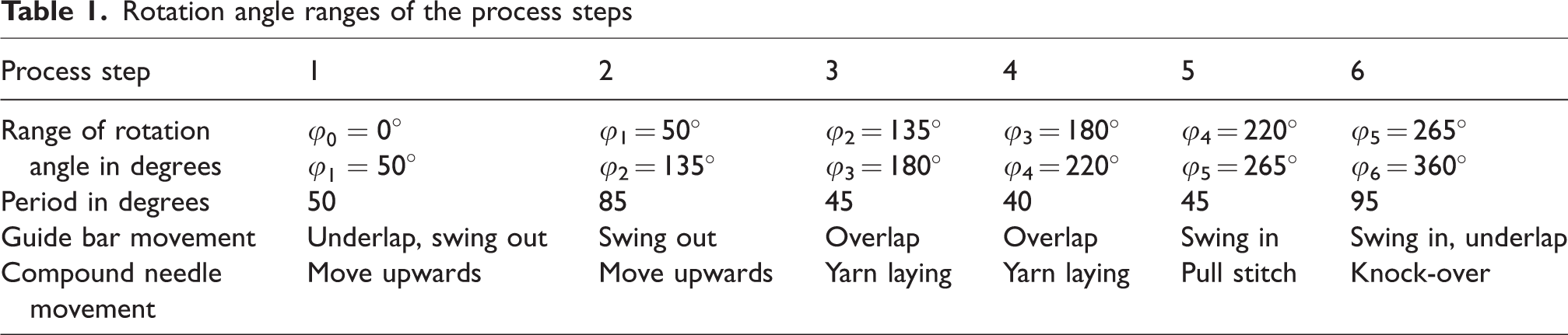
In order to understand the variations in yarn length required and yarn motion during the stitch formation process, the stitch formation process is divided into different sections (process steps). The individual yarn length variations of each process step are then combined to form the total yarn path during the entire stitch formation process of a machine revolution. The stitch formation process can be divided into individual sections according to the movement of the warp knitting machine elements.20,23 In this paper, the stitch formation process is divided into six individual process steps. The stitch formation process starts with the knock-over sinker holding back the warp knitted fabric and an underlap movement of the guide needles (first step). In the second step the compound needles move upwards, while the guide needles begin to swing out. Next, the guide needles finish the swinging out and start the overlapping movement over the compound needles (third step) in order to lay the yarn into the open compound needle head during the fourth process step. Subsequently, the compound needles move down to draw the stitch and the needle head closes (fifth step). To complete the stitch formation, the sinker knocks over the stitch during the sixth step. The total change in yarn length
Modeling of the stitch formation process steps
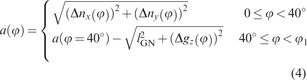
In the first process step (
During the second process step (
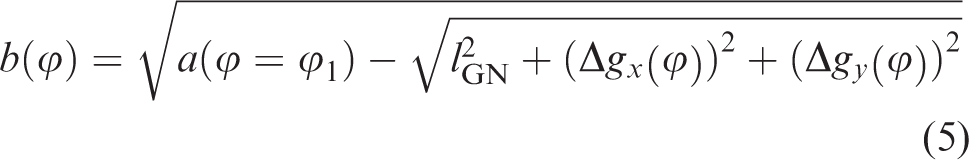
Yarn motion in the second process step.
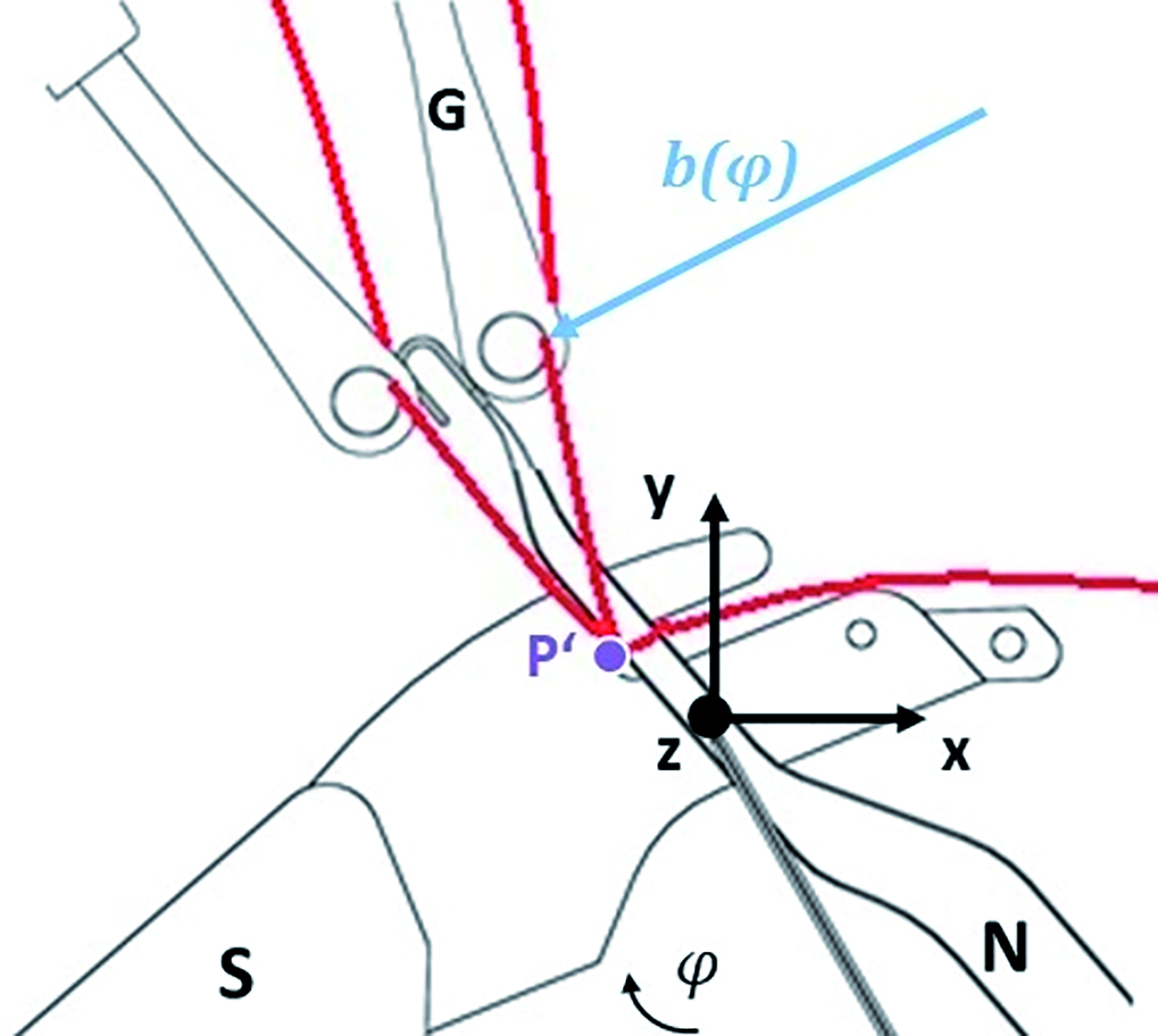
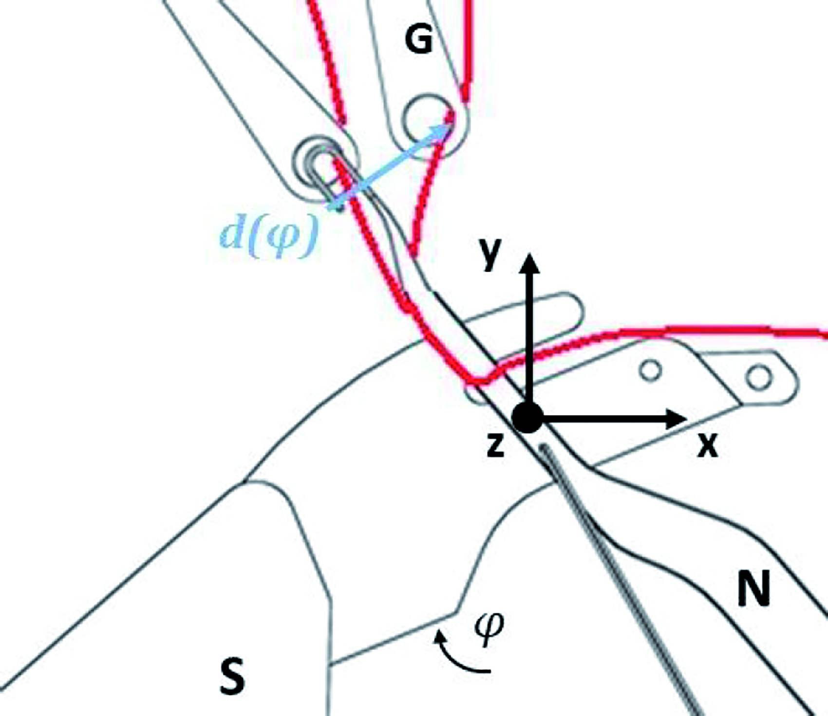
In the third process step (
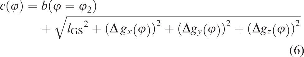
Yarn motion in the third process step.
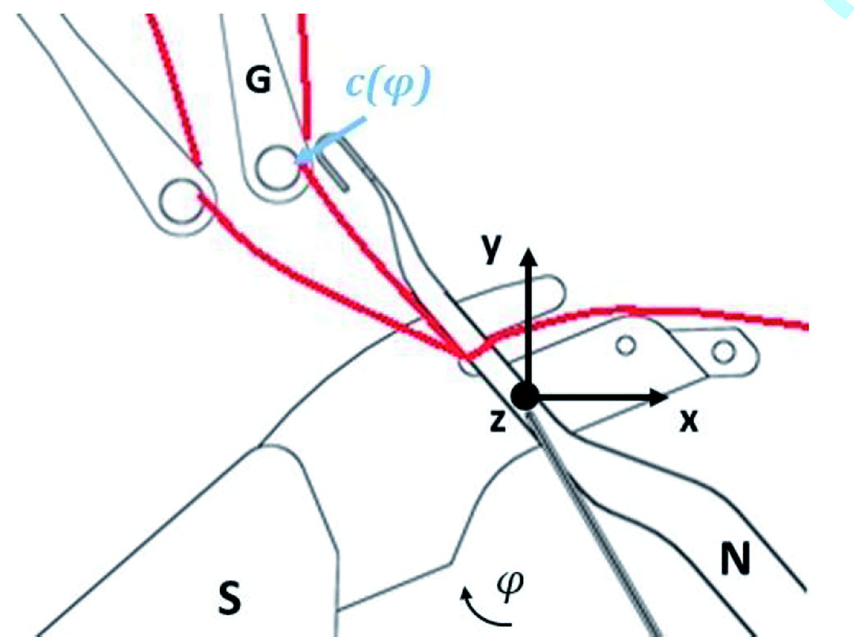
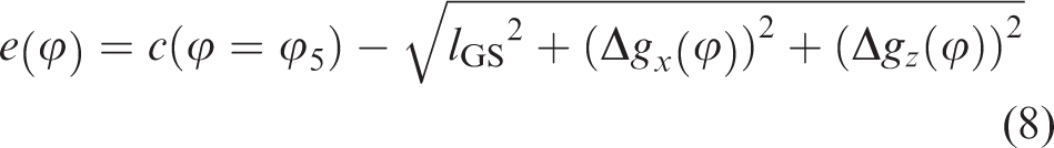
In the fourth process step (
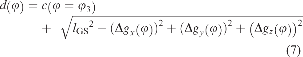
Yarn motion in the fourth process step.
During the fifth process step (
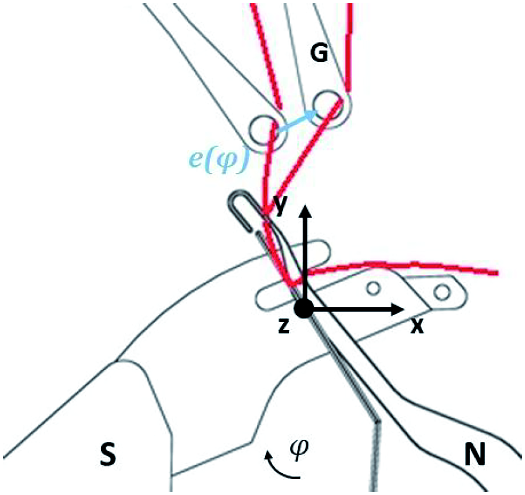
Yarn motion in the fifth process step.
In the sixth process step (

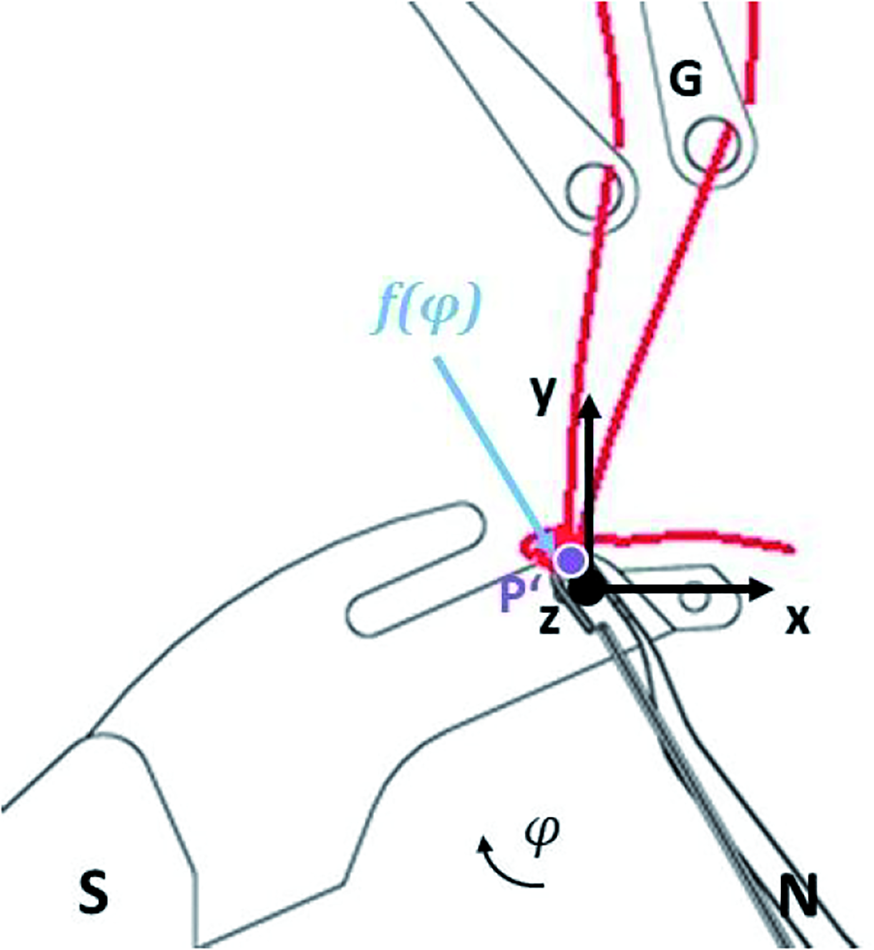
Yarn motion in the sixth process step.
The modeling of the yarn tension (

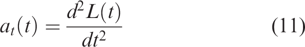
The yarn acceleration
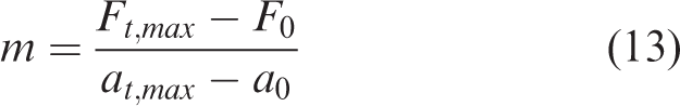
The mass
Based on equations (10) to (13), the modeled yarn tension

Validation of the model
In order to validate the designed model, the movement of machine elements influencing the stitch formation process was optically recorded and analyzed using high-speed cameras on the warp knitting machine Copcentra 3K (Karl Mayer Textilmaschinenfabrik GmbH) in a previous research work 24 (Figure 9). For these measurements, optical position marks were attached to machine elements (guide bar, compound needle bar, closing wire, sinker). These reference marks were optically detected by two high-speed cameras at different machine speeds (25, 100, 500, 1000 and 2000 rpm). A polyester multifilament yarn with a yarn count of 167 dtex was selected as the yarn material. In addition, the yarn motion was optically recorded for a machine speed of 25 rpm close to the stitch formation area. The yarn motion was not recorded at higher machine speeds so that the yarn motion would not be influenced by swinging of the yarn sheet. The data were processed using a dynamic 3D analysis software from GOM mbH.
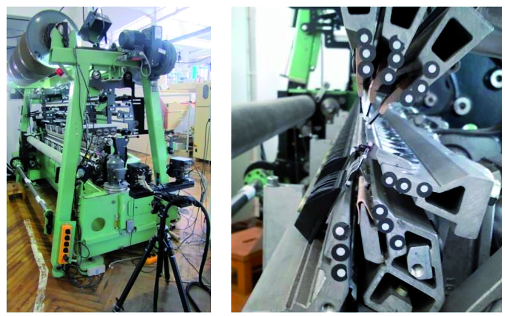
Set-up for measuring the movement of the machine elements.
Results and discussion
Movement coordinates of the warp knitting machine elements
The graph in Figure 10 shows the optically recorded movement of the machine elements in the warp knitting machine for a full 360 degrees rotation. The movement is in the combined x–y direction according to the stroke in the cam drive of the machine elements.
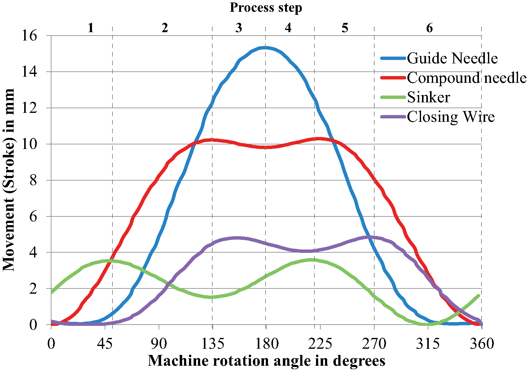
Movement curves of warp knitting machine elements.
As shown in the graph, the process flow of the warp knitting machine elements can be read in relation to the machine rotation angle. The compound needle is in its lowest position at a rotation angle of 0 degrees. The sinker reaches its holding-down position at an angle of 50 degrees. At an angle of 135 degrees, on the other hand, the guide needles begin their overlapping movement, while at 180 degrees they begin to swing. At 220 degrees, the sinker starts to move to the knock-over position. When the machine rotation angle exceeds 265 degrees, the closing wire closes the compound needle, followed by a joint movement to the lower zero position. This process flow enables the rotation angle ranges for each individual process step during stitch formation to be precisely defined (Table 1).
Rotation angle ranges of the process steps
Yarn path
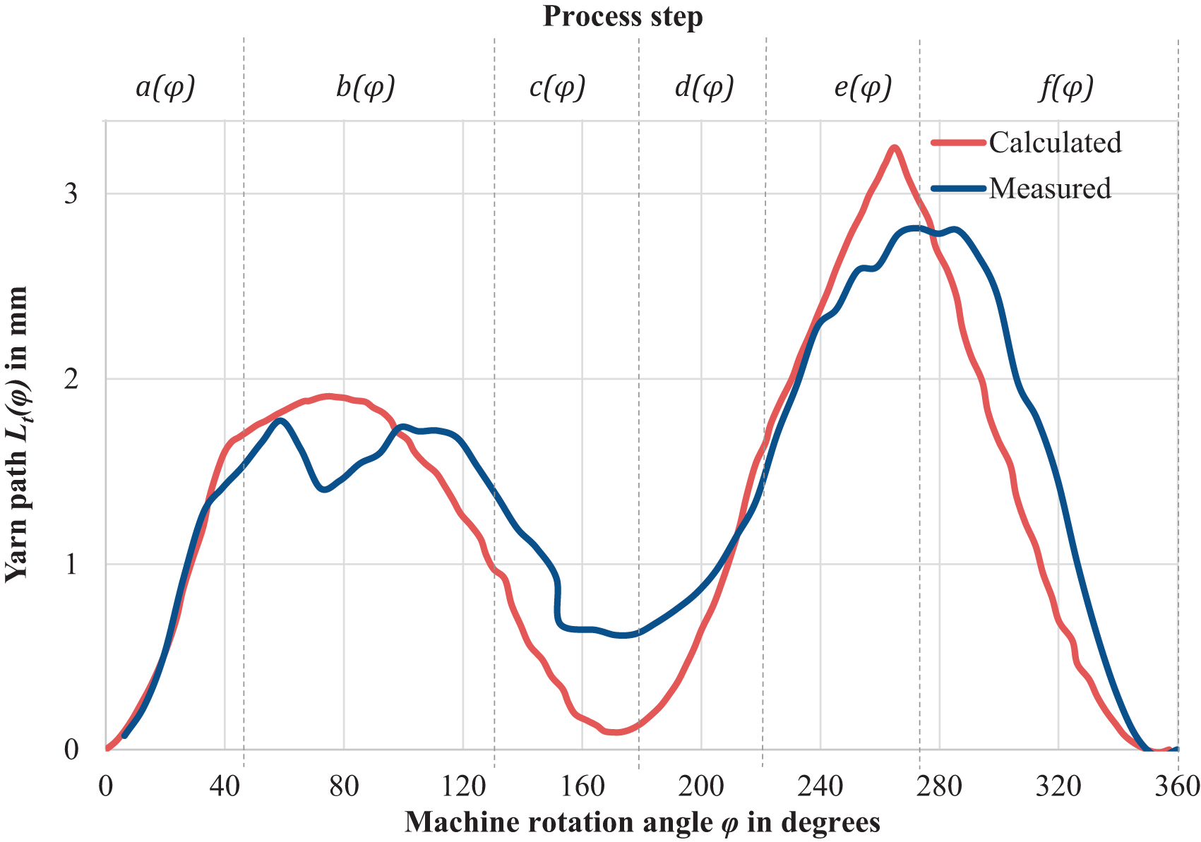
The experimentally recorded yarn motion compared with the modeled yarn path based on equations (1) to (7) is shown in Figure 11. The value of
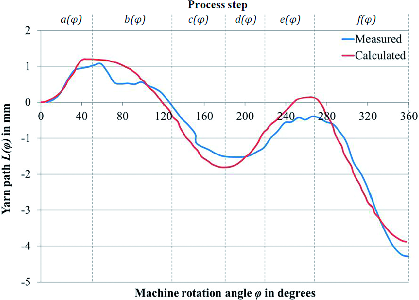
Experimental and calculated yarn path during stitch formation.
According to Figure 11, the calculated yarn path is similar to the measured curve. In agreement with the calculated curve, the measured curve reaches its peak at a rotation angle of 265 degrees, followed by a degression in the negative y direction. In the theoretically determined yarn path, the turning point at which the increasing curve begins to decrease is reached at an angle of 180 degrees due to the swing out. For the measured value, the turning point occurs between 180 and 200 degrees due to inertia at 25 rpm and yarn elongation. The yarn motion is measured above the machine elements, while the calculations are performed based on the warp knitting area. This results in a delay in the machine rotation angle. Furthermore, the maximum values of the yarn path of the measured curve are lower compared with the theoretically generated curve. This can be explained by the physical behavior of the yarn. That is, when the yarn path is determined based on vectorial calculations, friction and elongation are neglected as potential influencing factors, whereas they are included in the recording of yarn motion. Moreover, the yarn is affected by rollers and friction as it is taken up by the needles, thus causing the curve to flatten. However, all these effects result in only minor deviations between the theoretical and measured yarn path.
In the diagram of Figure 11 it can be seen that 4.3 mm of yarn was required for a full stitch formation at 360 degrees of machine rotation. It is also clear that the yarn demand fluctuates. However, the yarn delivery in the warp knitting machine is linear. From this, a linear yarn delivery rate can be derived (4.3/360 mm/degree). The yarn path has therefore been standardized in order to examine the variation of the yarn path in relation to the yarn delivery. The standardized yarn path is calculated from the modeled yarn path L(φ) as follows:
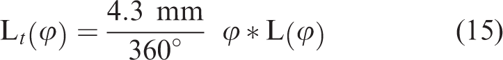
As shown in Figure 12, the yarn path is characterized by two sections of high variation in yarn demand during the stitch formation process. The first increase in yarn demand correlates with the underlap movement of the guide needles (step 1). The increase in yarn path at the start of the machine rotation results from the upward movement of the yarn after stitch formation and knock-over from the previous machine rotation. The release of the yarn path at 80–240 degrees machine rotation angle is due to the upward movement and position of the compound needle. The greatest change in yarn path and yarn demand during stitch formation is at 270 degrees machine rotation angle when the stitch is knocked over (step 5). The modeled path has slightly higher maximum values compared with the measured yarn path. These differences can be explained by the yarn elongation at high yarn tension, which is not included in the model.
Normalized yarn path during stitch formation considering linear yarn delivery.
Yarn tension
The yarn tension is determined theoretically using equations (8) to (12), assuming a machine speed of 25 rpm. The low speed is chosen because of the optical measurement of the yarn path for the validation of the model was carried out at the same speed. In addition, the model was to be validated without taking into account oscillation of the yarn sheet that occurs at high machine speeds. A basic yarn tension of
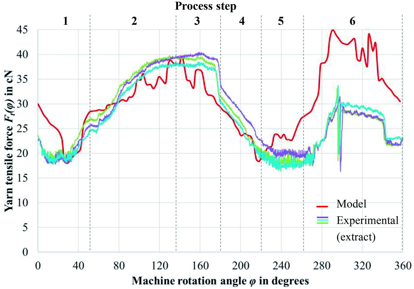
Experimental and calculated yarn tension during stitch formation.
The modeled yarn tension curve is similar to the experimental curve and will be analyzed below. The curve shows that the main influences on the yarn tension are the swinging movement of the guide bar and the needle movement performed during process steps 2 and 6.
The comparison of the yarn tensions also shows a good correlation between the calculated and measured curves. However, due to the lack of consideration of the yarn elongation properties and the rolling and friction effects on the yarns, the yarn force deflections of the calculated and measured curves are significantly higher. For accurate modeling, the elongation properties and the yarn tension compensator must be taken into account. The good correlation between the two curves shows that the model covers the main factors influencing the yarn path and yarn tension during stitch formation in warp knitting machines.
Conclusions
The generated geometric model of yarn path and yarn tension enables the determination of the main factors influencing the yarn path during stitch formation processes in warp knitting machines, that is, guide needles and compound needles. The model and its validation have shown that the movement parameters in terms of the amount and acceleration of the guide needles and compound needles have a significant influence on yarn path and yarn tension. Thus, predictions can be made depending on geometrical changes of the warp knitting elements and stitch formation area in order to estimate yarn path and yarn forces. This provides a sound basis for the research and development of digital twins in the textile industry and the improvement of warp knitting processes. For the knock-over step of stitch formation, the model has the largest deviation from the experimental analysis due to the tension compensator releasing the yarn. To improve the model, it is also relevant to consider integrating the tension compensator as well as yarn elongation, friction and damping properties into the model.
Footnotes
Declaration of conflicting interests
The author(s) declared no potential conflicts of interest with respect to the research, authorship, and/or publication of this article: The funders had no role in the design of the study; in the collection, analyses, or interpretation of data; in the writing of the manuscript; or in the decision to publish the results.
Funding
The author(s) disclosed receipt of the following financial support for the research, authorship, and/or publication of this article: This work was supported by the German Research Foundation, DFG (project no. CH174/44-1).