
Abstract
The threat posed by buried explosive charges and their explosive dispersal of environmental debris is associated with a variety of debilitating injuries. The dispersion profile of such threats includes particulate in a broad range of particle length scales, which are more destructive to ballistic fabrics than larger particles alone. Smaller particles are initially dispersed at higher speeds, degrading armour fabrics prior to the arrival of the larger penetrating particulate. In the present work, we present a low-cost industrial abrasion test method to investigate the abrasive wear in neat and polymer-coated ballistic fabrics to determine the level of degradation of the fabrics under the abrasive load. These fabrics were subjected to the impingement of an abrasive jet with average particle velocity of 187 ± 20 m/s. The results showed evidence of significant degradation and failure within the ballistic fabrics, that would certainly influence their subsequent ballistic performance. The addition of polymer coatings was able to reduce the abrasive degradation of the fabrics. The failure modes of the polymer composites are similarly described. This methodology shows promise as a means of armour material screening for this particular threat.
Advances in personal protective equipment, battlefield medicine, and the ability to evacuate battlefield casualties rapidly have led to increased soldier survivability of injuries that were once fatal. As a result, debilitating injuries to the extremities accounted for approximately half of the total injuries to coalition forces in Iraq and Afghanistan. 1 This injury profile is exacerbated by the fact that the extremities of soldiers often go unprotected due a variety of ergonomic factors (e.g. comfort, maneuverability, and added weight). Less prevalent than extremity injuries, accounting for approximately 5% of injuries, were complex genitourinary injuries (e.g. wounds to the urinary system or genitalia). 2 While occurring less frequently than other injuries, genitourinary injuries have an arguably higher psychological cost to soldiers after returning home. 3 The threat posed by buried explosive charges and their explosive dispersal of environmental debris (e.g. sand and rocks) is commonly associated with these genitourinary injuries.
When a buried explosive charge is detonated, the soil cap directly above the charge can have an initial velocity upwards of 1000 m/s; 4 however, this solid soil plug is short-lived as it breaks up on radial expansion and the peak ejecta velocity drops rapidly on expansion. The velocity of this plug can drop below 500 m/s within 1.5 ms, 4 which can be within approximately 1 m of travel. These results are consistent with measured particle dispersal speeds measured in particle beds accelerated by a central spherical explosive charge.5,6 The threat to soldiers from buried explosive charge ejecta (the surrounding environmental materials dispersed by the explosion) depends on a number of factors, such as charge size, soil type, charge depth, and the travel distance from the explosive charge to the area of concern (e.g. the femoral artery and groin). These factors determine the velocity bounds of the ejecta, the ejecta density, and ejecta fragment size, which ultimately factor into survivability and injury profiles. Ballistic groin protectors with metal or composite cups have been introduced to provide protection, but have not seen widespread use due to ergonomic considerations. 3 Undergarments consisting of multilayered ballistic fabrics (i.e. blast boxers) provide a more ergonomic solution that has seen broader use. Their primary purpose is to mitigate the effects of these environmental ejecta propelled by the explosion of a buried explosive charge.
The environmental ejecta threat is complicated by the size, morphology, and speed distributions within the ejecta, as well as the many-body aspect of an ejecta plume impact. The ejecta, which mainly consists of sand and rock, also have a lower density and different strength properties than typical ballistic fragments and bullets. Dwivedi and colleagues7,8 used a 6 mm diameter glass sphere to replicate the soil debris threat in an investigation of ballistic performance among various ballistic fabric types, setting aside multibody impact effects. These results showed the trade-off between fabric performance and ergonomic factors. Van der Jagt-Deutekom and Westerhof 9 subjected trouser fabrics to secondary ejecta from explosive charges buried in soil at close range, investigating different charge sizes, stand-off distances, and soil types. This work used a synthetic gel backing to replicate the response of tissue. Ouellet and Pageau 10 developed a surrogate torso model consisting of a silicone rubber skin and neoprene foam backing producing quantified response corridors to replicate the torso response. Representative armour backings and evaluation techniques are necessary to model the real performance of the armour system and potentially link performance to injury outcomes.
The study of Van der Jagt-Deutekom and Westerhof 9 found that the STANAG soil, consisting of a broad range of grit sizes, caused more ripping and general damage than the uniform soil. This was attributed to the variation in grit sizes, but perforations were primarily attributed to larger particles. 9 Similar observations were made by Saunders and Carr, 11 who noted the penetration of both large and small particles with evidence of abrasive damage in the vicinity of the larger perforations. Small particulate tended to penetrate between the gaps in fibers and yarns while larger particles were associated with tensile failure of the yarns. The authors noted that the penetration of small particulate into soft tissue is associated with elevated infection risks and requires significant medical intervention. 11 Gabriel et al. 12 used X-ray computed tomography to locate fragments of different shapes and sizes within a synthetic gel surrogate to demonstrate a possible approach to injury evaluation following buried explosive ejecta arena tests.
The phenomenological description of explosive particle dispersal is particularly important to the performance of armour solutions when considering the more aggressive damage caused by the dispersion of mixed-size particulate seen in buried explosive charge testing.9,11 For instance, the interaction and independent roles of the blast wave, small particulate, and larger particulate on the damage of the armour are important to the overall performance of armour under these explosive dispersal loading conditions. The work of Frost et al. 5 experimentally demonstrated several important phenomenological aspects of the dispersal dynamics, investigating particles of different sizes. Their results showed that within 1 m of travel, smaller particles (under 0.463 mm diameter) were moving faster than large particles (0.925 mm diameter), and impacted their gauge surface ahead of the larger particles. At further distances, the smaller particles decelerated quicker than the large particles. Given that the large soil particles are significantly larger than those studied by Frost et al., 5 the near-range speed differential between large and small particles may be even greater.
Thus, in the event of explosive dispersal of soil debris, these data suggest that smaller debris may impact the armour fabrics prior to the larger particles associated with perforation. As a result, the multibody dynamics of high-speed fine particle ejecta impacts may lead to local yarn abrasion that may weaken the fabrics prior to the arrival of the larger perforating ejecta, facilitating the perforation process. This phenomenological description would be consistent with the observations made in prior blast ejecta studies.9,11 The abrasive degradation of the yarns immediately prior to large particle impacts could be a multibody aspect of the ejecta threat that has not been adequately considered. This would mean that optimizing the design of a protective undergarment would require knowledge of both the abrasive response of the fabrics as well as their ballistic response against representative threats.
The damage mechanisms associated with the small particulate impacts should be similar to the standard abrasive blasting erosion, which is the process of impacting a surface with a high-speed abrasive particle jet (i.e. sandblasting). In the present study, we evaluated a new test methodology for investigating the abrasive erosion of ballistic yarns in a manner that is consistent with the small particulate ejecta from explosive dispersal. The investigation involved a series of ballistic fabrics and different polymeric coatings to improve their resistance to abrasive yarn damage. This approach will enable a quick ranking of material performance against this threat without the prohibitive costs associated with explosives testing used in prior studies.
Materials and methodology
Materials and sample preparation
The abrasive tests were conducted with two fabric types and three polymer coatings. The fabrics that were tested were a 600-denier KM2+ Kevlar (36 × 36 yarns per inch) and a 600-denier Dyneema (31 × 31 yarns per inch). The three polymer coatings consisted of an adhered polyurea layer, a none-adhered polyurea layer, and an adhered halloysite nanotube (HNT)-reinforced polyurea layer. In total, eight sample types were investigated, four with each fabric type. The neat fabrics consisted of two plies of fabric, while all of the coated samples had a single fabric ply. These are summarized in Table 1.
A summary of the material samples tested in the present work
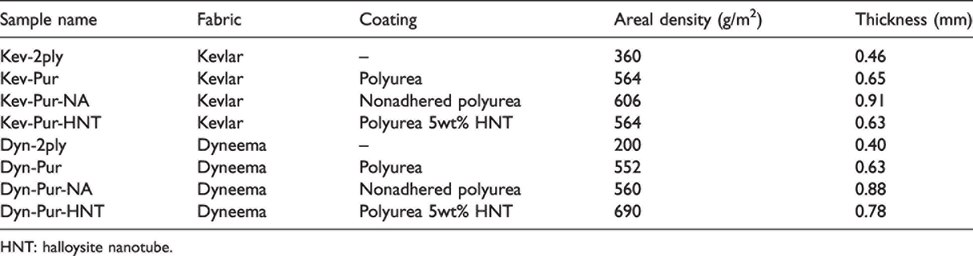
HNT: halloysite nanotube.
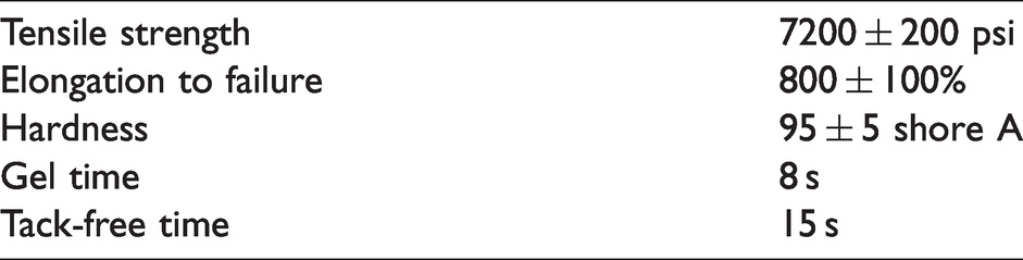
The polyurea used in this study was sourced from ArmorThane USA under the trade name UltraBlast. It is a two-component 1:1 mix ratio, fast set, spray applied hybrid polyurea elastomer. Component A contains isocyanate and component B contains an amine. The manufacturer-provided mechanical properties are shown in Table 2. UltraBlast polyurea was selected for this study due to its high tensile strength, elongation, toughness, and flexibility.
UltraBlast polyurea mechanical properties as supplied by the manufacturer
Due to the rapid gel time of the polyurea, it is typically applied using a direct impingement spray. A high-solids spray (HSS) printing apparatus was designed to allow us to print sheets of the polymer, as well as to integrate particles into the polymer. The apparatus used to produce the polyurea samples has been previously described in greater detail for the interested reader. 13
Several steps were taken to prepare the polymer for printing. Component B was mixed with a high shear mixer for 1 min per gallon as per the manufacturer’s instructions. Components A and B were both decanted into separate beakers, heated to a temperature of 90°C and subsequently allowed to cool to 50°C. Component B was lightly mixed to distribute evenly any moisture scavenger that may have settled out during the heating process. The components were loaded into separate 300 ml cartridges, which were then loaded into the printing apparatus. The aerosolizer valve on the nozzle was set to 60 psi and placed in its fully open position. The electrically driven HSS flow rate dial was set to 4. The printing gantry moved at a rate of 7.5 m/min in the X direction with a step-over speed of 25∼m/min in the Y direction. The level of porosity in the neat polyurea samples produced using this process was measured to be 14.8%, which compared favorably with 14.1% porosity measured in polyurea samples produced by the manufacturer using a direct impingement mixer. Cross-sectional views from a scanning electron microscope (SEM) of an adhered polyurea Kevlar and an adhered polyurea Dyneema sample are shown in Figure 1. The interface of the polyurea and Dyneema show evidence of localized melting in the Dyneema as a result of the exothermic cure process.
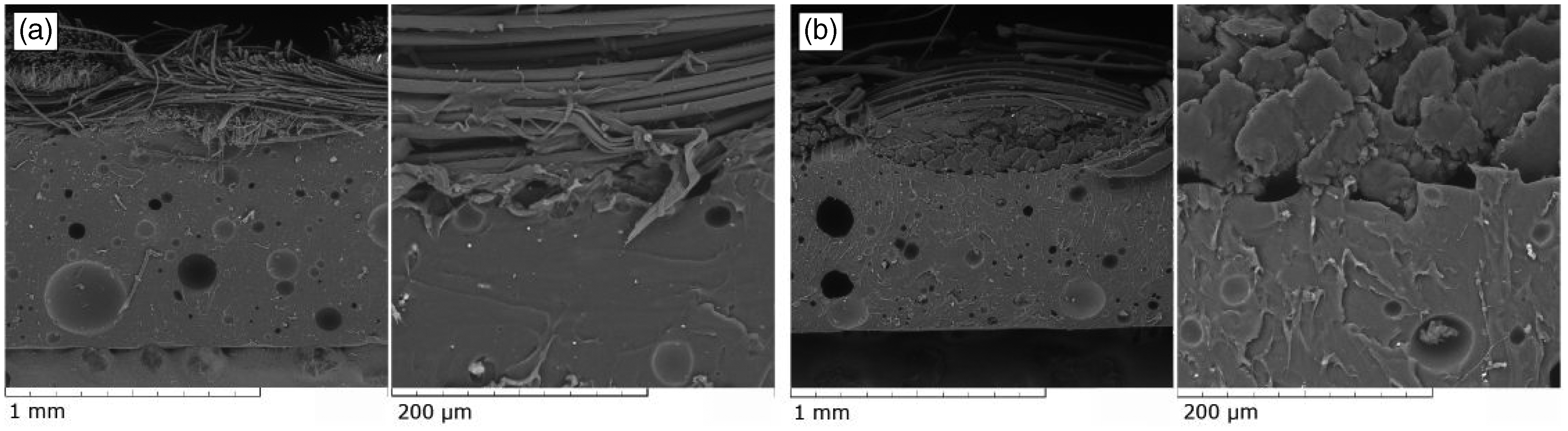
(a) Scanning electron microscope (SEM) images at two scales of the interface between the sprayed polyurea and the Kevlar yarn and (b) SEM images at two scales of the interface between the sprayed polyurea and the Dyneema yarn.
HNT-reinforced samples were prepared in the same manner as the neat samples with the exception that after decanting components A and B, the HNT content was carefully mixed in equal part into both components to achieve a total HNT mass fraction of 5%. A sonicator probe was used to improve the dispersion of the HNT within the polymer components. Sonication caused the components to heat up to a temperature of between 80°C and 90°C, the components were then allowed to cool to a temperature of 50°C before proceeding as per the afore-mentioned printing details.
During the polymer spray process, the ballistic fabrics were held taut onto an aluminum substrate positioned 400 mm below the nozzle. To ensure consistent polymer deposition, the initial portion of the spray was discarded away from the main printing substrate, prior to the main production print sequence. Following polymer deposition, the samples were placed in an oven for a post-cure treatment at a temperature of 80°C for a period of 24 h. Finally, the material samples were cut into 150 mm by 150 mm square specimens.
To produce the nonadhered polyurea layers, prior to printing, a Kevlar substrate was generously coated with a silicone mold release to facilitate separating the polymer sheet from the Kevlar after the post-cure process. This approach produced a better surface finish than spraying directly onto an aluminum substrate, as the wicking effect of the Kevlar helped polyurea droplets coalesce into a more uniform sheet. This enabled thinner and more uniform sheets of polyurea to be produced. The nonadhered polyurea sheets were then edge-stitched onto pristine Kevlar or Dyneema fabric samples.
Abrasive apparatus design
Abrasive testing was conducted at RLD Industries Ltd. in Ottawa, ON, Canada. The apparatus for these tests is shown in Figure 2(a). The test apparatus consisted of a commercial-grade abrasive pressure blaster that was fitted with a Kennametal SN159-5XL 12 nozzle to achieve higher abrasive speeds. The Kennametal SN159-5XL 12 is a 305 mm long Laval nozzle with a 7.9 mm throat and 17.8 mm exit diameter (Figure 2(b)). This nozzle is capable of producing supersonic air speeds at the nozzle exit; however, the ejected abrasive will lag this airspeed. Given the nozzle geometry, the air speed at the nozzle exit should be in the range of 570–635 m/s. Settles and Garg 14 computed the particle exit velocity for sand from a Laval nozzle, finding that the particle exit speed was approximately 30% of the free-stream air speed for a 850 µm sand particle. This specific nozzle was selected for the study as we estimated our abrasive particle speeds would be in the range of 170–200 m/s, using an isentropic flow analysis along with the computational data from Settles and Garg. 14
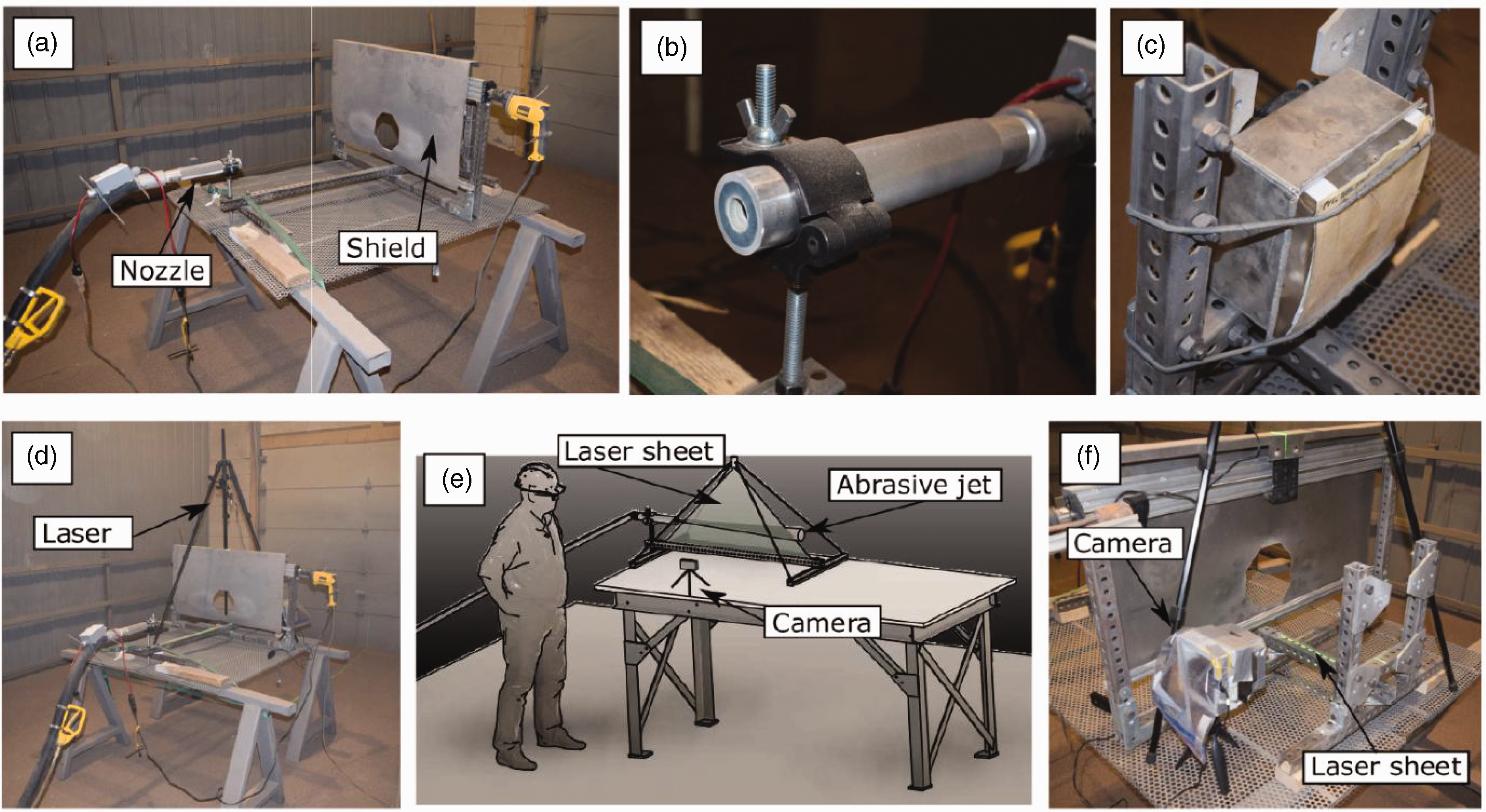
Photographs of (a) the abrasive testing apparatus configuration; (b) the Kennametal SN159-5XL 12 nozzle; (c) the sample retention method; (d) the particle image velocimetry (PIV) set-up showing the placement of the laser module; (e) a graphical representation of the PIV set-up and (f) the PIV measurement area showing the laser sheet and high speed camera.
The abrasive pressure blaster consisted of a pressurized tank holding the abrasive, a feed valve, and a 9 m feed hose connected to the spray nozzle. The nozzle was securely held 1000 mm away from the target samples. The samples were held behind a protective shield with a window that was used to control the exposure of the fabrics to the abrasive jet. The protective shield was fixed to a ball screw that moved the shield laterally across the abrasive jet. The protective shield ensured that the fabrics were protected from the initial transience in the abrasive flow and that the fabrics were exposed to a consistent free-stream flow. The average exposure time was 4.7 s ± 0.5 s, which resulted in an average impacting abrasive mass of 76 ± 1 g per experiment through the 76 mm diameter hole in the protective shield.
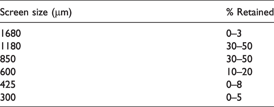
JetMag 16-60 abrasive (Les Sables Olimag Inc.), a synthetic olivine pyroxene sand, was used as the abrasive. The material composition of the abrasive is shown in Table 3, while the particle size distribution is shown in Table 4. The supplier provided material properties for the abrasive. The bulk density was quoted to range between 2.72 and 2.94 g/cm3, while the Mohs hardness was between 7.0 and 7.5. SEM images of pristine abrasive and abrasive recovered from the adhered polyurea Kevlar specimen are shown in Figure 3. The abrasive shown in this SEM was recovered from the space in between the delaminated polyurea layer and the Kevlar layer. The change in particle size among the recovered samples should be attributed to dynamic milling of the abrasive as it travels through the feed hose and nozzle rather than the fabric specimens.
Material composition of JetMag 16-60, as provided by the manufacturer
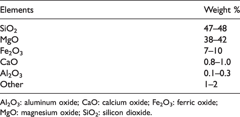
Al2O3: aluminum oxide; CaO: calcium oxide; Fe2O3: ferric oxide; MgO: magnesium oxide; SiO2: silicon dioxide.
Screen analysis of the JetMag 16-60 provided by the manufacturer
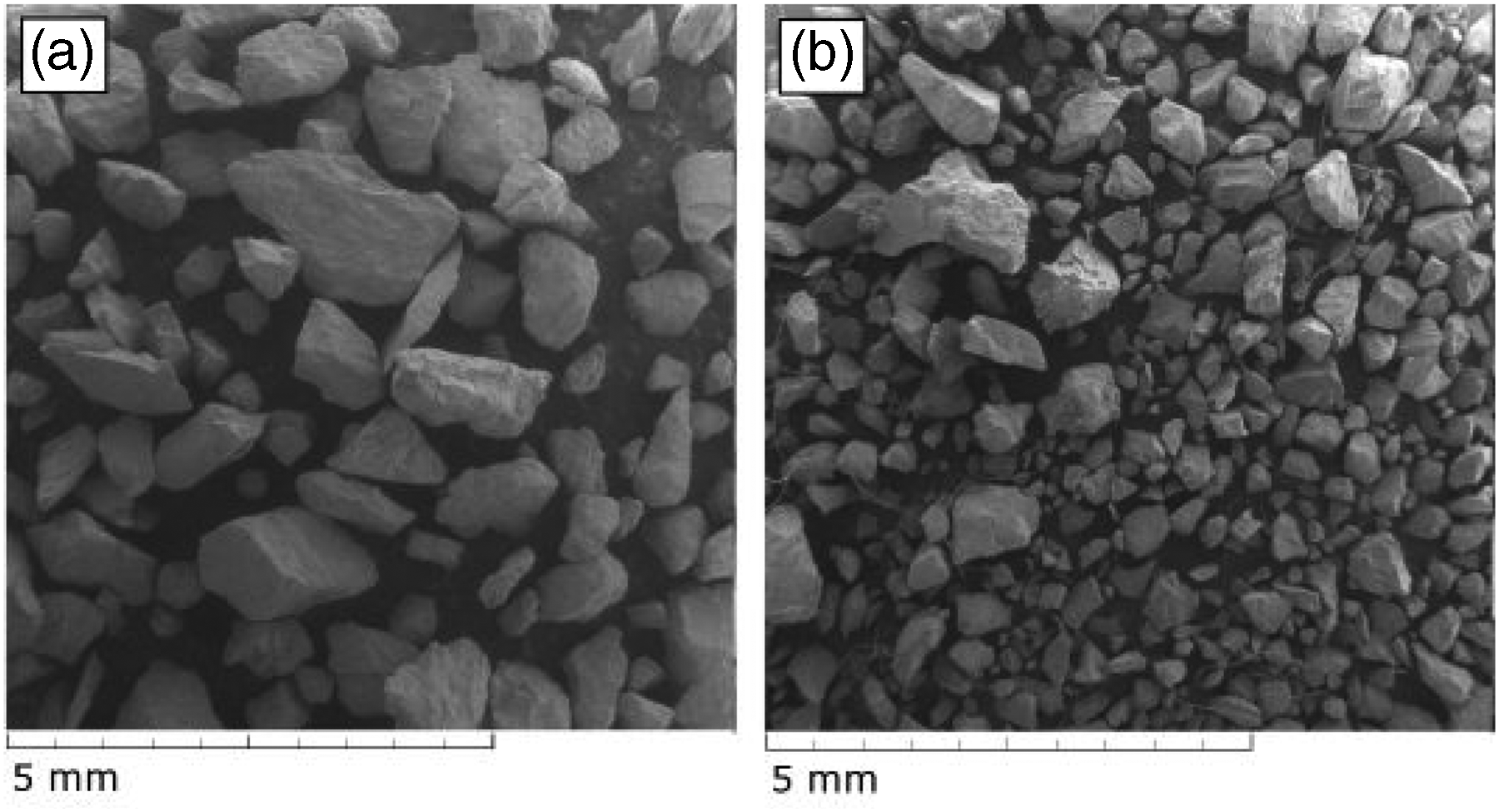
Scanning electron microscope (SEM) images of the (left) pristine JetMag 16–60 and the (right) recovered JetMag 16–60.
Each fabric sample had a set of fabric elastics sewn at their top and bottom edges, which were used to hold the samples to a 50 mm thick 20% ballistic gelatin block (Clear Ballistics LLC), as seen in Figure 2(c). These gelatin blocks acted as the tissue-simulating backing for these tests. The elastic attachment was used rather than a rigid clamp in order better to replicate the conditions of an armour system that would be worn in the field.
Particle image velocimetry
Particle image velocimetry (PIV) was used to determine the abrasive speed in the free stream prior to impact (Figure 2(d), (e), and (f)). The PIV system consisted of a 532 nm green laser sheet with an exit pupil diameter of 0.8 mm and a maximum power of 200 mW, purchased from NaKu Technology Co. The laser was positioned above the abrasive jet with the laser sheet in the center of the jet parallel to the abrasive flow. A Sony RX100 IV 20.1 MP camera operating on high-frame rate mode (960 fps and 1/12800 s shutter speed) was used to record the abrasive jet motions. The abrasive speed was determined using PIVlab, a plug-in for MATLAB. 15
Due to the trajectories of the particles exiting the abrasive nozzle, the thickness of the laser sheet, and the speed of the particles, no particles appeared on two consecutive frames. As a result, the speed of the abrasive media was determined by streak velocimetry. Twenty frames of the brightest streaks were selected from the high-speed video, there were 30 light streaks recorded on these frames. The range of measured abrasive velocities was between 159 and 231 m/s, with an average velocity of 187 m/s. These particle speeds are on the lower end of the ejecta measurements made previously, 9 and within the expected range of particle velocities based on the earlier estimates for the nozzle geometry as well as the computational results of Settles and Garg. 14
Results
Following exposure to the abrasive jet, photographs were taken of the front and rear surfaces of each recovered sample (Figure 4). Due to a jam in the abrasive feed hose the Kev-Pur-NA sample (Figure 4(c)) was not exposed to the full abrasive jet. There were varying degrees of damage seen in these fabric samples, ranging from complete failure to limited surface damage. The damage was investigated through SEM images of the surfaces. In the event of complete failure of the polyurea or underlying ballistic fabric, sections of the damaged edge were used for imaging. Material failure modes observed from these SEM images are described below. The results for the Kevlar and Dyneema samples are presented separately.
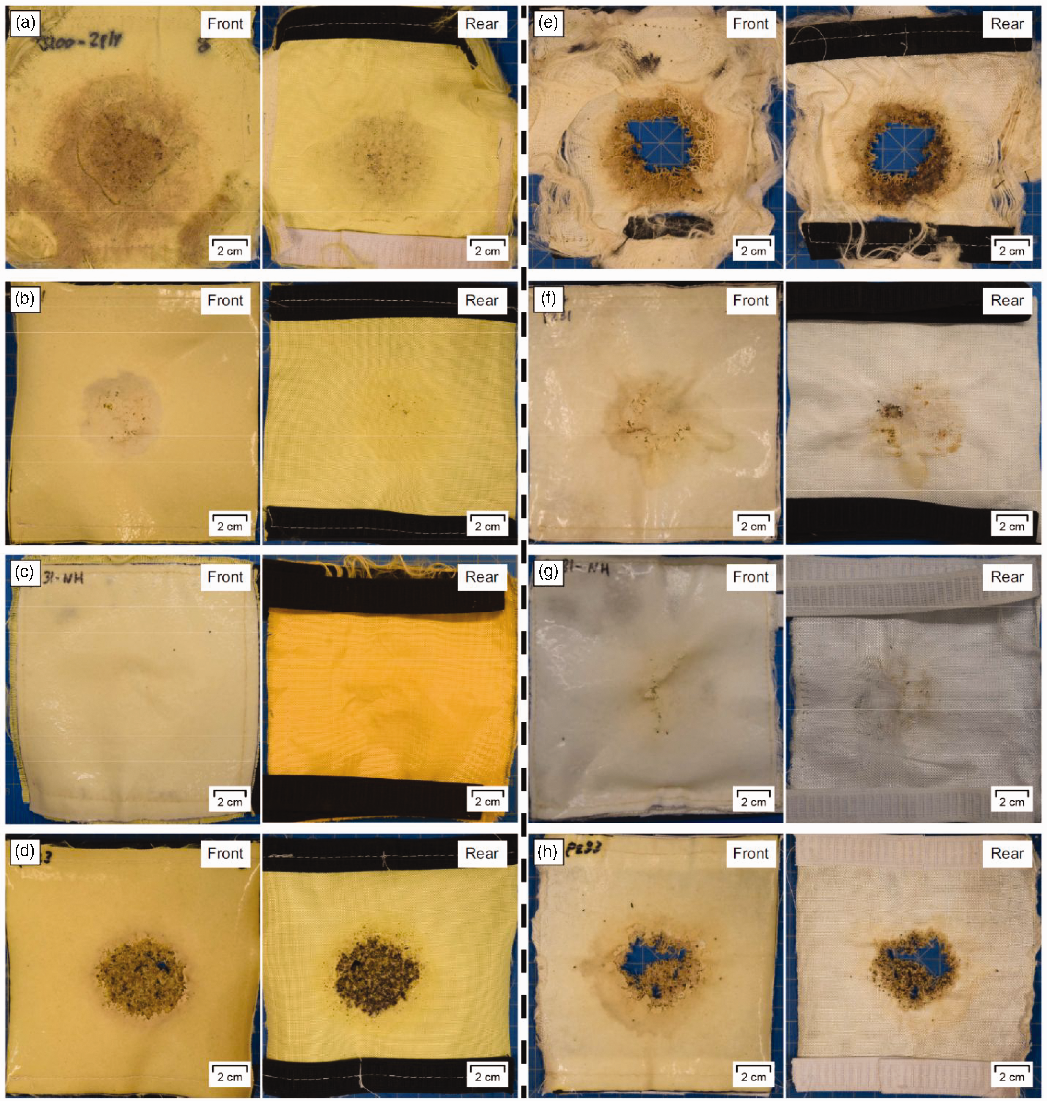
Photographs of the impact (front) and rear fabric surface for the eight material samples: (a) Kev-2 ply; (b) Kev-Pur; (c) Kev-Pur-NA; (d) Kev-Pur-HNT; (e) Dyn-2 ply; (f) Dyn-Pur; (g) Dyn-Pur-NA and (h) Dyn-Pur-HNT. For each set, the impact and rear surfaces are shown on the left and right, respectively. HNT: halloysite nanotube.
Kevlar samples
The impacted surfaces of all Kevlar-based samples are shown in Figure 5. From these images, we can make some specific observations relating to the material response to the small particulate.

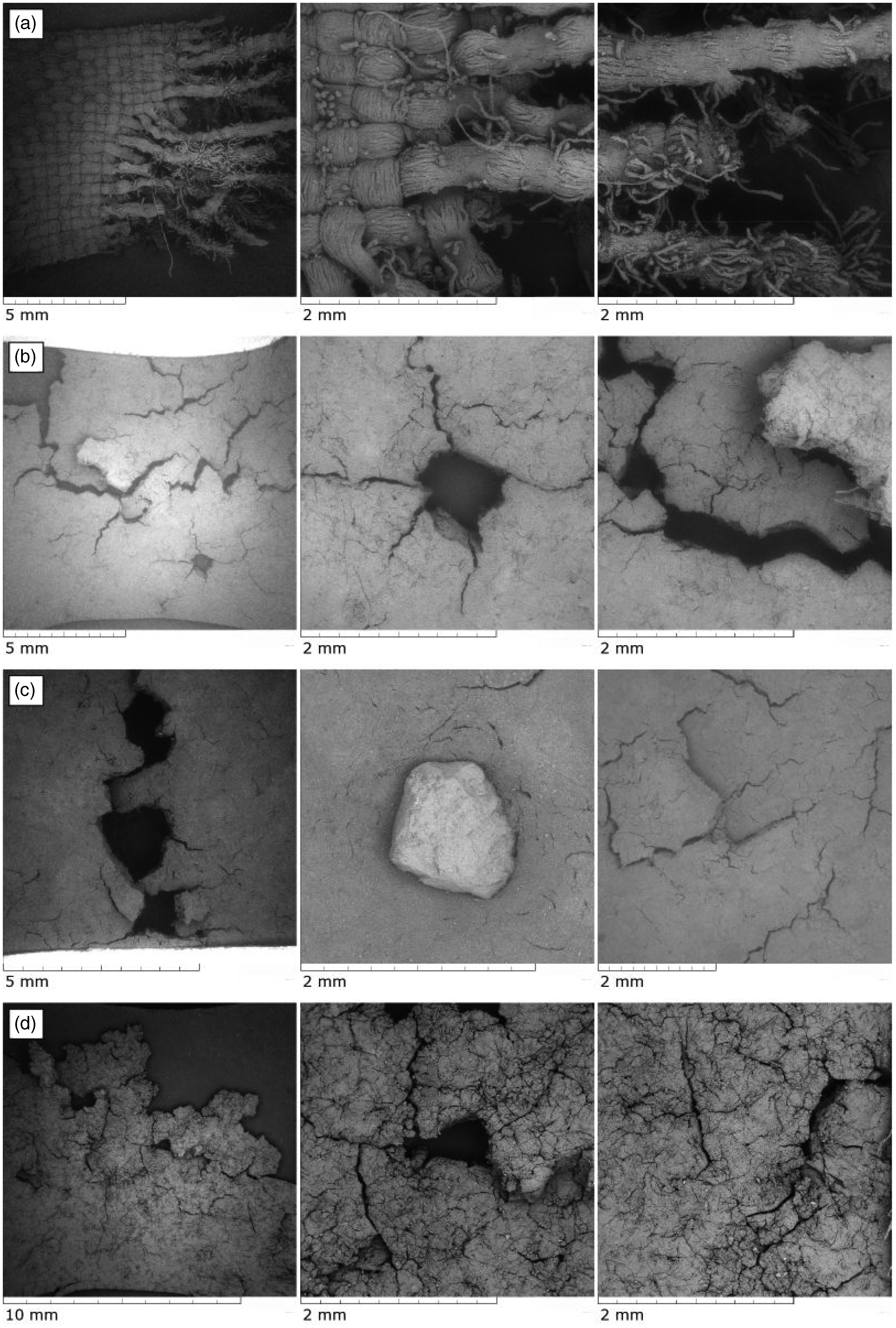
Scanning electron microscope (SEM) images of the impact surfaces of the various samples: (a) Kev-2 ply; (b) Kev-Pur; (c) Kev-Pur-NA and (d) Kev-Pur-HNT. HNT: halloysite nanotube.
The direct impact of the abrasive media on the 2-ply neat Kevlar sample caused complete failure of the top layer and caused significant damage to the underlying layer (Figure 4(a)). The larger abrasive particles were able to penetrate through the fabrics. In Figure 5(a), there is a significant amount of small abrasives that have been trapped in the Kevlar and there is significant damage to the yarns of the fabric, with a large number of fiber ends as well as a window from a large particle penetration. The woven structure of the fabric is no longer evident from this impact surface, which would consistent in a loss in performance for subsequent impacts.
The addition of a polyurea layer on the surface of the Kevlar improved the survivability of the fabric layer. The pure polyurea coatings (Figure 4(b) and (c)) outperformed the polyurea nanocomposite involving HNT (Figure 4(d)), with clear evidence of penetrations through the latter sample. The polyurea-HNT nanocomposite was considered due to a series of recent studies demonstrating superior mechanical and ballistic performance of polyurethane nanocomposites due to the integration of HNT changing the spherulitic microstructure of the polymer.16–18 There is also evidence of dynamic material property improvements for particle-reinforced polymers at high-strain rates, 19 provided that there is adequate surface wettability of the particles. 20
There were two samples with pure polyurea layers, one which was adhered to the Kevlar substrate, and another that was nonadhered. For the adhered polyurea layer (Figure 5(b)), there is evidence of shear and tensile failures in the polymer layer. There is evidence of brittle cracking in the surface, and there was significant delamination of the polymer from the Kevlar, which can also be seen from the discolouration in Figure 4(b). Some small abrasive particles were able to penetrate entirely through the entire specimen. The nonadhered polyurea layer also had evidence of tensile failure of the polymer, likely due to bending-induced stresses, but shear failure was not observed (Figure 5(c)).
The addition of HNT to a polyurea nanocomposite did not improve the performance of the material system, but resulted in a worse performance against this threat. The brittle fracture lines that were evidence in the pure polyurea sample adhered to the Kevlar were similarly visible, but at a finer scale (Figure 5(d)). Shear failure is similarly visible. There was also complete failure in the underlying fabric (Figure 4(d)).
Dyneema samples
The impacted surfaces of all Dyneema-based samples are shown in Figure 6. The neat Dyneema samples had completely failed from the abrasive load (Figure 4e). A look at the SEM images of the failed edges of the Dyneema sample showed evidence of localized melting of the yarns in addition to the abrasive/ballistic failure of the fabrics (Figure 6(a)). Given that the polyurethane used in the Dyneema sample is a thermoplastic, this was not unexpected, as it appears that it was unable to handle the physical and heat loads associated with the successive abrasive impacts. These effects were mitigated by the addition of neat polyurea coating layers to the fabric (Figure 4(f) and (g)).
Scanning electron microscope (SEM) images of the impact surfaces of the various samples: (a) Dyn-2 ply; (b) Dyn-Pur; (c) Dyn-Pur-NA; and (d) Dyn-Pur-HNT. HNT: halloysite nanotube.
Many of the observations were made for the coated Dyneema samples were similar in their performance when used with Kevlar. The polyurea layers did not prevent all particle penetrations, as evidenced by the photographs of the front and rear surfaces of the samples (Figure 4(f) and (g)). The SEMs show evidence of tensile and shear failures of the polymer layers in both the adhered polyurea (Figure 6(b)) and the nonadhered polyurea (Figure 6(c)). The impacts resulted in the delamination of the polyurea layer from the Dyneema fabric substrate (Figure 4(f)).
The addition of HNTs resulted in a reduced length scale of tensile fractures that corresponded to a degradation in the performance of this fabric solution (Figure 6(d)). The Dyneema fabric behind the polyurea-HNT nanocomposite showed the same failure type seen in the neat Dyneema fabrics (Figure 4(e) and (h)).
Discussion
Given the distance between the buried explosive charge and a soldier that could benefit from a protective undergarment, there is a significant small abrasive dispersal that will hit the armour system immediately prior to the larger penetrating fragments. Any damage sustained by the fabrics in that initial abrasive phase will make the armour system susceptible to failure. Thus, the use of standard industrial abrasive equipment can provide useful insights into the abrasive performance of ballistic fabrics.
Experimental evidence suggests that during the explosive dispersal of particles, small particles (smaller than 500 microns) will lead the ejecta cloud, resulting in significant abrasive loads that precede the arrival of larger penetrating particles. 5 As a result, any degradation of a ballistic fabric prior to the arrival of the larger particles in the ejecta field that have a higher likelihood of penetrating the armour fabrics will reduce the overall performance of the armour system, particularly with respect to its single particle impact V50 performance. The abrasive testing in the present work demonstrates the destructive effects of an abrasive load from the many high-speed impacts of small particles on the yarn structure of Kevlar (Figure 5(a)) and Dyneema (Figure 6(a)). The Kevlar weave shows signs of disruption of the woven structure in the regions impacted by the particles (Figure 5(a)), while the Dyneema fibers show signs of localized melting and failure (Figure 6(a)). This degradation of the initial fiber structure will make the fabrics susceptible to lower energy penetrations and effectively reduce the ballistic limit of the fabrics. While the timescales associated with this degradation are not known, the increased destructive nature of soil combining large and small particles was seen empirically in buried explosive charge arena testing by Van der Jagt-Deutekom and Westerhof. 9
While the abrasive load from these many small particles on the yarns degrade their structure, making them more prone to penetration, our results demonstrated that it is possible to design a polymer coating or layer that will prevent this abrasive weakening. Interestingly, the decoupling of the polymer layer from the fabric appears to improve the survivability and performance of this layer, based on our observations. This may be the result of the failure behavior of the polymer coatings themselves, which may have been altered by the boundary condition provided by the fabric substrate. When we examined the failure modes in the polymer, we saw evidence of both shear and tensile failure; however, the extent of the fractures in the adhered layer were observed to be greater. The nonadhered polyurea sample front surface had less damage than the adhered polyurea samples. This outcome is likely related to the coupling of the motion between the polyurea and the fabrics prior to delamination. The presence of a coupled backing substrate will alter the tensile load on the polymer during an impact, affecting the strain distributions and failure in the polymer.
The polymers reinforced with HNT performed poorly compared with their nonreinforced counterparts. The addition of the HNT into the polyurea resulted in a much finer fracture scale, despite the expectation of a particle-reinforced structure within the polymer due to the presence of the nanotubes. The HNT increased the stiffness of the polymer, reducing its ability to absorb energy through elastic deformation, leading to extensive fine scale fractures.
All Dyneema samples were subjected to significant thermal damage during testing. Interestingly, the nonadhered polyurea layer reduced the thermal damage through the entire thickness of the underlying Dyneema fabric more than the directly adhered polyurea. Recall that the application of the spray polyurea to the Dyneema itself caused local melting, so the thermal damage on the back of the fabric may be due to a difference in heat conduction during testing or differences in the contact stresses in the yarns.
These neat and composite material observations have implications for improving the design of soft armours for buried explosive charge ejecta dispersal, and this test methodology was shown to be a cost-effective approach to material screening for this purpose. Further work is required to understand the nature of the degradation caused by the inclusion of small particles in an explosively dispersed set of aggregate, particularly the role of these particles in causing a reduction in ballistic resistance to larger particle penetration.
Conclusions
The present study provides a better mechanistic understanding of the increase in the destructive nature of ejecta fields with a large range in particle sizes. When combined with terminal ballistic characterizations of the armour systems, this abrasive test provides a cost-effective method to improve the design choices and the overall performance of these undergarment armour systems. The abrasive loading of the ballistic fabric systems, both with and without polymer layers, showed evidence of a broad range of behaviors and failure modes that would help predict their performance against explosive soil ejecta.
The abrasive degradation of the neat ballistic fabrics, through local melting (Dyneema) and a destruction of the woven structure of the fabric (Kevlar) demonstrates how the abrasive load increases the susceptibility of the fabrics to subsequent impacts. Whether this damage occurs on a timescale necessary to degrade the performance of the fabrics in an explosive dispersal environment is still an open question that will need to be answered in future work. The addition of a polymer coating on the ballistic fabrics was shown to be effective at reducing the abrasive damage to the underlying ballistic fabrics.
Footnotes
Declaration of conflicting interests
The author(s) declared no potential conflicts of interest with respect to the research, authorship, and/or publication of this article.
Funding
The author(s) disclosed receipt of the following financial support for the research, authorship and/or publication of this article: This work was funded through the Innovation for Defence Excellence and Security program under contract no. W7714-186568.