
Abstract
This article presents a novel approach for the electrical interconnection of embroidered conductive yarns with each other at defined cross-points using ultrasonic spot welding. The electrically conductive yarns are made of silver-coated copper microwires plied with polyester filament fibers into a hybrid embroidery yarn. In this study we evaluated the influence of different material properties (number of microwires of conductive yarn, fabric substrate, and adhesive film), the embroidery designs of contact pads, and the main parameters of the welding process (energy, force, amplitude, and tools) on the welded interconnection. The results were evaluated by the process yield and the contact resistance of the welded contacts. The electrical contacts were then tested for long-term reliability (elevated temperature and humidity, temperature shock change, bending, washing and drying) and analyzed. In addition, the contacts were examined with scanning electron microscopy (SEM) and micro-computed tomography and in the form of cross-sections with optical and SEM techniques to discuss interconnection and failure mechanisms. The results show that ultrasonic spot welding can enable the production of highly reliable interconnections of textile-integrated conductive yarns with contact resistances of a few milliohms that are resistant to mechanical, environmental, and washing conditions, leading to potential new manufacturing processes of e-textiles.
Keywords
Electronic textiles (e-textiles)1,2 combine the advantages of two worlds – the flexible properties, wearability, and wide range of applications of textiles with electronic functionality. With the emergence of new materials and technologies in the field, the range of applications is constantly expanding.3,4 For example, heating, lighting, or sensor functions are integrated in novel clothing and automotive and interior products.5,6 A progressive trend is further developments for the functionalization of conductive yarns with sensor properties or optimized conductor materials for the realization of large-area flexible systems.7,8 Thereby, the integration of temperature, humidity, pressure, and strain sensors in textiles is of particular interest.9–11 In such a heterogeneous smart textile system, a low-ohmic conductor material is selected to realize a power or signal transmitting line, while another material can be used for heating or sensor functions. For this purpose, at least two textile-integrated conductors must be electrically connected to one another to implement the desired functionality. In another application case, the interconnection of several textile-integrated conductors from the same conductive material is used to create a conductive pattern.
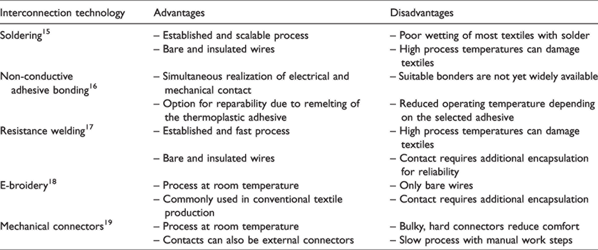
Those ultra-flexible, textile-integrated electronic systems place high demands on the electrical interconnection and are usually not compatible with conventional soldering processes. Problematic are the high process temperatures in the soldering process, typically of 250–400°C, which can burn textile materials, as well as high dynamic mechanical loads in wearable applications or washing of e-textiles, which can damage brittle soldered joints and thus cause contact failure. 12 Hence, alternative interconnection technologies for soldering textile-integrated conductors are increasingly being developed and applied, which, for example, use mechanical fastenings and/or are carried out at room or low temperature.13,14 The advantages and drawbacks of those current interconnection technologies for textile-integrated conductors are shown in Table 1.
Comparing standard technologies for interconnecting textile-integrated conductors
However, many contacting methods still lack the combination of economy and process properties suitable for textiles. Therefore, new concepts for the development of textile-compatible interconnection technologies based on ultrasonic plastic welding techniques are currently being researched. Ultrasonic welding is a well-established, cost-effective, and ultra-fast joining process for a wide range of applicable materials and applications, for example for the realization of wire bonds as chip connections, as seams for plastic packaging, for waterproof textile products, or as a weld seam for medical products. 20 For the manufacturing of e-textiles, continuous ultrasonic plastic welding was firstly investigated to be used for bonding conductive stripes as transmission lines onto textile substrates.21–23 Another study reported that current-carrying textile-based conductor strips for contacting heatable nonwovens can also be processed using the continuous welding process. 24 The latest publications describe the investigations into ultrasonic spot welding as a technology for connecting textile-integrated conductors.25,26 It was also recently reported that electronic modules can be electrically and mechanically integrated on textile-based circuit boards by means of ultrasonic plastic welding. 27
This research focuses on the realization of stable, low-resistance electrical contacts between crossing hybrid conductive yarns by ultrasonic spot welding. In the next section we describe the influence of materials (e.g. type of conductive yarn and textile substrate, design of the yarn crossing, and selection of the inlay material) and process parameters (welding energy, force, oscillation, and sonotrode shape) on the process. We then present the experiments and analysis of the interconnection tests, followed by a brief discussion of the experimental results.
Materials and methods
Conductive materials for e-textiles are selected on the basis of their electrical and mechanical properties and can be in the form of metallized polymer yarns, hybrid conductive yarns, or conductive polymers threads.28–30 The conductor materials can be coated with a protective layer to avoid material-typical defects, such as abrasion of the metal coating, as well as to protect against environmental influences or short circuits.31,32 For our tests, bare hybrid conductive yarns were selected because of their good electrical performance.
Hybrid conductive yarns
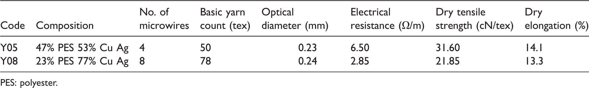
Hybrid conductive yarns consist of standard fibers, especially based on polyester (PES) or polyamide (PA), and conductive metal microwires based on stainless steel, copper, brass, nickel, or ferrous alloys. Depending on the metal chosen, conductive or resistive knitted or woven fabrics are possible, as well as the realization of electronic embroidery (e-broidery).33,34 E-broidery can cover variable conductive patterns and functional elements, such as temperature or humidity sensors, antennas, heating elements, etc. Suitable conductive embroidery yarns are commercially available from companies such as Swiss-Shield 35 or Clevertex. 36 For our research, the two different types of hybrid yarns manufactured by Clevertex were selected because of their low electrical resistance compared to metallized polymer yarns. In Table 2 an overview of the most important material parameters of the selected hybrid conductive yarns is given.
Parameters of the used hybrid conductive yarns
PES: polyester.
Both yarns consist of PES continuous monofilament fibers with an average diameter of 14.5 µm (each monofilament). Figure 1 depicts the construction of the selected two types of conductive hybrid yarns.
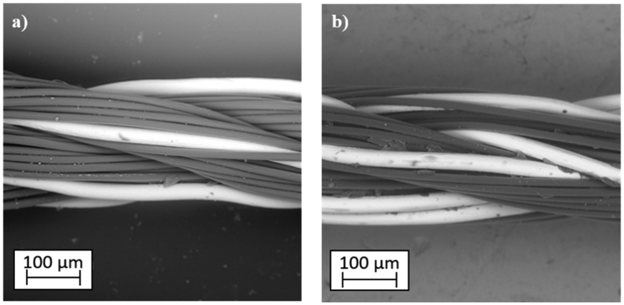
Two selected types of conductive yarn used for ultrasonic plastic welding – longitudinal view: (a) hybrid yarn Y05 – HI-COND art. 53 (four Cu/Ag microwire + polyester yarns) and (b) hybrid yarn Y08 – HI-COND art. 74 (eight Cu/Ag microwire + polyester yarns).
Selection and assessment of textile base substrates
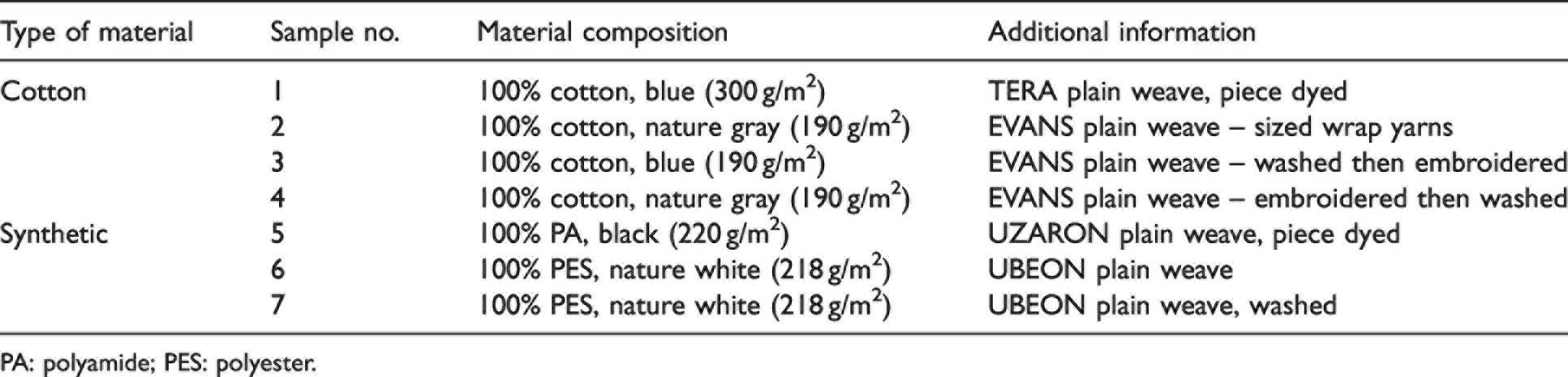
The contact test patterns were embroidered onto the various textile substrates with both types of hybrid conductive yarns. The goal of this part of the research was to specify mechanical–physical properties and determine the behavior of the textile substrates during the welding process. Altogether, seven types of textile substrates (four cotton-based substrates and three substrates made of synthetic or blend materials) were tested for the embroidery of conductive tracks (see Table 3 for an overview of the selected textile substrates).
Textile substrates used for ultrasonic welding
PA: polyamide; PES: polyester.
During this study, it was found that the textile substrates based on synthetic materials are not well suited for ultrasonic welding. The polymer parts of the hybrid conductive yarn are melted together with the textile substrate yarns during the ultrasonic welding process. This creates a stiffened contact area, which can cause (i) the breaking of microwires during the mechanical stress on the interface of the rigid welded area and soft and flexible conductors and (ii) decreasing of textile integrity. The best test results were achieved with substrate No. 3 (100% cotton, 190 g/m2, EVANS plain weave – washed then embroidered, nature blue color), both in terms of embroidery quality and in combination with the subsequent welding tests. For further studies, substrate No.3 (depicted in Figure 2(a)) was pre-washed, which helps to stabilize the dimensions (shrinking) and mechanical properties of textile substrates because a thin film of starch is applied on the surface of the yarns to give strength and smoothness so they can endure the tensions during the weaving process. This film was released during the first washing cycle. Textile substrates were washed according to method 4N from the European Standard EN ISO 6330 – Domestic washing and drying procedures for textile testing. 37
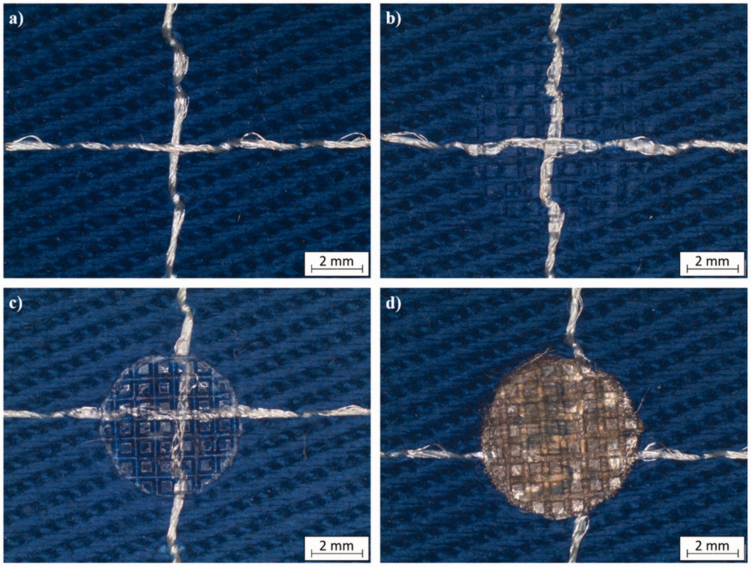
Microscopic images of the crossing of conductive hybrid yarns: (a) before ultrasonic welding; (b) after ultrasonic welding of hybrid yarns; (c) after ultrasonic welding of hybrid yarns with added thermoplastic polyurethane (TPU) film and (d) after ultrasonic welding of hybrid yarns with added TPU and conductive fabric.
Selection and assessment of thermoplastic insert materials
The ultrasonic plastic welding is based on the process of melting the thermoplastic material in the weld area and subsequent fixation of the joined materials by its solidification under the pressure. The strength of the welded joint therefore depends on the amount of melted material at the weld. Hybrid conductive yarns contain thermoplastic PES fibers, but the amount is not sufficient for proper adhesion or encapsulation of the welded interconnection. The number of PES fibers in the hybrid yarns used is 47 wt.% for yarn Y05 and only 24 wt. % for yarn Y08.
Within this research, it was verified in preliminary welding tests (parameter ranges for energy from 1 to 100 J, force from 100 to 400 N, and amplitude from 18 to 36 µm) that the addition of another thermoplastic material into the welding area can significantly improve the reliability and durability of the realized joints. Thermoplastic polyurethane (TPU) films have been chosen as suitable insert materials because they have good weldability and very good adhesion to textiles. Beside the TPU films, silver (Ag) and copper (Cu) metallized fabrics made from polymer fibers were also tested as additional suitable insert materials. The metallization of conductive fabrics can create multiple electrical contacts among the individual microwires of ultrasonically welded hybrid conductive yarns and reduce the contact resistance of the welded interconnection. The melted fibers of metallized polymer fabric can increase mechanical durability of the welded joint, like in case of TPUs. Figure 2 depicts the various concepts for creating a reliable interconnection.
In total, eight different TPU films and four different metallized fabrics, that is, the nonwoven Ag-plated fabric Shieldex® Bonn, the Cu-plated nonwoven fabric Shieldex® Kiel + 30, the Cu-woven fabric Shieldex® Kassel RS, and the Ag-plated knitted fabric Shieldex® Balingen, were selected and thermally analyzed. The measurements of the thermal properties of insert materials, in particular the enthalpy of fusion, were carried out by means of differential scanning calorimetry (DSC). DSC curves were recorded using a DSC Q2000 differential scanning calorimeter from TA Instruments. The samples (2.7–6 mg, based on a sample), sealed under aluminum pinhole pans, were in a reheating mode (heat–cool–heat) and scanned from –80°C to +210°C (TPU-based materials) and from –80°C to +300°C (metallized fabrics), followed by controlled cooling and by the second heating run at a heating rate of 10°C/min under a nitrogen atmosphere with a flow rate of 50 ml/min. The results of DSC analyses are given in Table 4.
Evaluated thermal properties for tested samples of insert materials
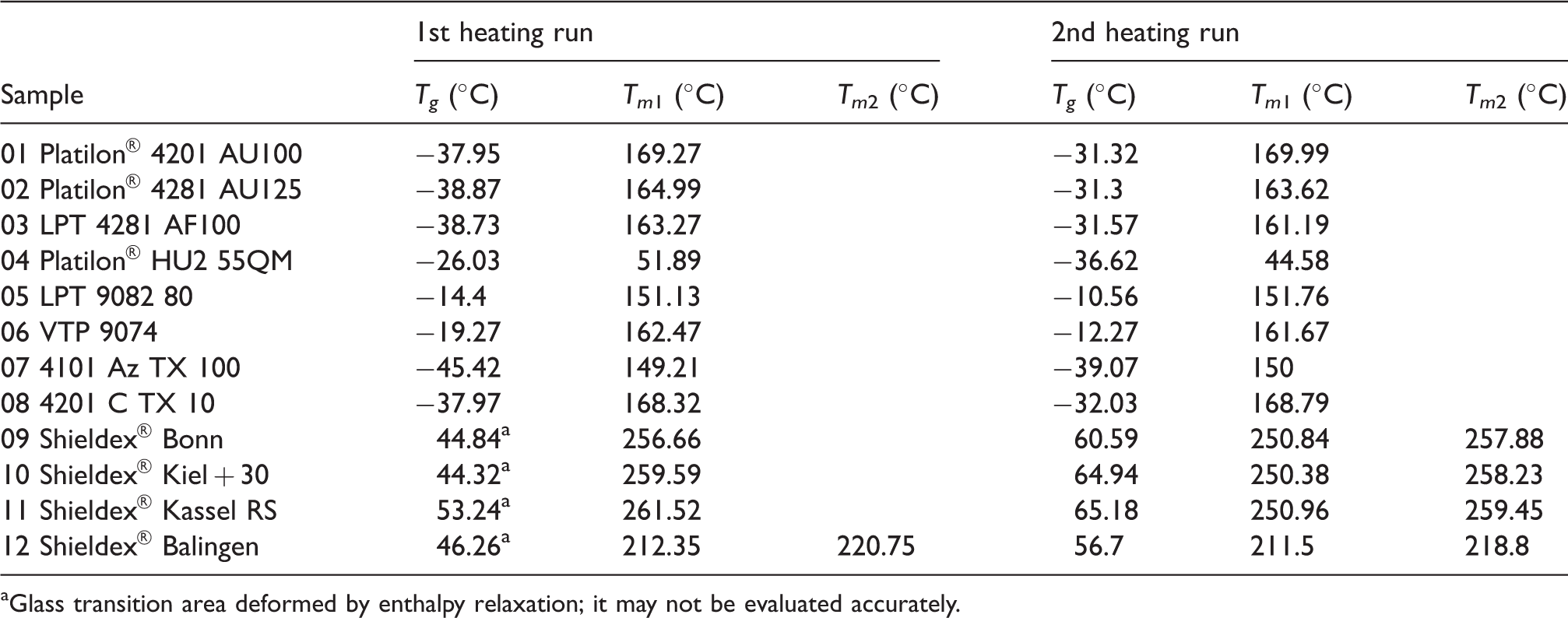
aGlass transition area deformed by enthalpy relaxation; it may not be evaluated accurately.
According to Netzsch, 38 the endothermic step around –38°C (mid-point) during the first heating reflects the glass transition of the soft segments of the sample. In addition, the curve exhibits an endothermic peak between 0°C and 210°C. The reversible part of it, which can be detected again in the second heating, is caused by the melting of the hard (thermoplastic) segments. The irreversible part is probably due to evaporation of volatiles or distribution of additives in the polymer matrix. For the metallized fabric samples (no. 09–12), the glass transition during the first heating run is difficult to analyze due to endothermic reaction, probably connected to enthalpic relaxation or evaporation (not visible during the second heating run after controlled cooling – removing the thermal and mechanical history of the sample). Measured thermograms for metallized fabric samples (no. 09–12) have visible double melting peaks. These double (or multiple) melting peaks may be due to the melting–recrystallization–remelting phenomenon in which thickening of lamellae occurs due to the occurrence of at least two distinct crystal populations. 39 Peak maxima are noted as a Tm1 and Tm2 in these cases.
From all analyzed TPU materials, the TPU film with the highest softening temperature was selected for further evaluation, as the welding process implies high energy in a short period of time. The DSC curve for this sample is shown in Figure 3. The TPU film exhibits slight movement of the glass transition from –38°C for the first to –31°C for the second heating run, almost identical melting temperatures of 169.27°C for the first heating and 169.99°C for the second heating, and low enthalpy of fusion with approximately 9 J/g. From analyzed metallized fabrics, the Ag-plated nonwoven fabric Shieldex® Bonn was selected because it shows very low surface resistivity (see also Table 5 for a comparison of electrical properties of the selected metallized fabrics), dense structure, and low fraying during the insert preparation and handling as well as significantly more resistance against oxidation in comparison to copper metallization. In addition, it is reported that nonwovens are more suitable for welding than knitted or woven fabrics, and here, too, the metallized staple fibers, which are only slightly fixed to one another, enable better sliding during the mechanical movements of the ultrasonic process, whereby the conductive fibers are more easily incorporated into the contact matrix to be generated. 40 The DSC curve for Shieldex® Bonn is shown in Figure 4. The melting point is around 256°C and the glass transition point around 60°C for the second heating run. The other suitable conductive fabric, Shieldex® Balingen, was no longer used because of the more complicated production of the insert in the form of a precise circular shape because of its poorer dimensional stability and the above-mentioned lower suitability for welding.
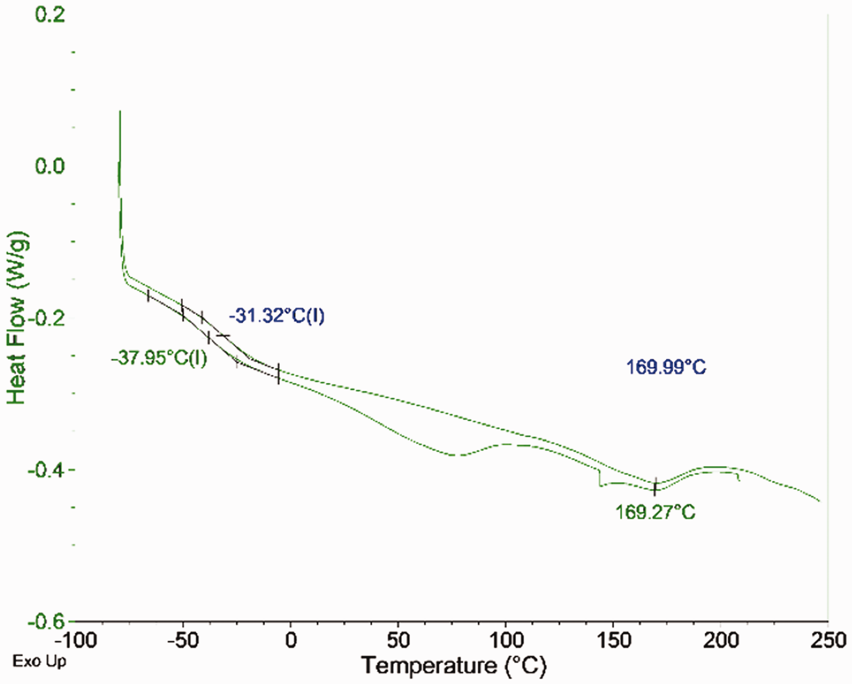
Differential scanning calorimetry thermogram of sample 01, Platilon® 4201 AU100 (heat–cool–heat run).
Electrical resistance and resistivity of selected metallized fabrics
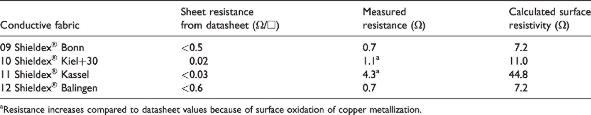
aResistance increases compared to datasheet values because of surface oxidation of copper metallization.
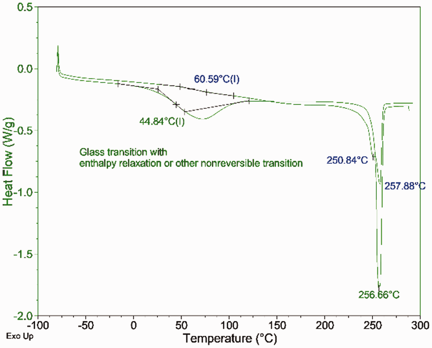
Differential scanning calorimetry thermogram of sample 10, Shieldex® Bonn (heat–cool–heat run).
Design of the test pattern
For easy evaluation and comparison of the impact of the welding process parameters and materials on the contact resistance of the welded joint, uniform test patterns were designed. The patterns were intended to be used for a four-wire contact electrical resistance measurement. This measurement method eliminates the influence of embroidered conductor resistance, the resistance of contact probes, and the resistance of interconnection cables, and thus only the contact resistance of realized joints was measured. The designed patterns were transferred to Designer7 software, which is used by the embroidering machine Bernina QE750, and embroidered using hybrid conductive yarns Y05 and Y08, both as the top and the bobbin yarn.
Several types of patterns were realized and are depicted in Figure 5. The first test pattern consisted of two hybrid yarns that were embroidered with a 90° crossing angle in the contact area (shown in Figure 5(a)). The stitch length appeared to be around 4 mm. The PES primary material of the yarns was melted in contrast with the conductive microwires during the welding process. The microwires of hybrid yarn were just deformed by welding pressure and fixed in a position by melted PES. The hybrid yarn contact area in the case of the first design is very small, because there is only one crossing of yarns. Based on that, only a few electrical contacts of microwires among crossing yarns can be achieved. The reliability of these contacts under mechanical stress was not sufficient, because the electrical contacts often cracked. For this reason, the second pattern with the embroidered pad on the crossing of threads (depicted in Figure 5(b)) was designed to increase the reliability and reproducibility of electrical contact. As a result, the number of electrical contacts of microwires was significantly increased, and there was also more melted PES material for the fixation of microwires and electrical contacts. It must be noted that no significant influence of the embroidery order of the first and second yarn layers on the contact resistance was observed. The further fixing and achieving higher reliability and durability of welded joints can be done using additional TPU insert and test pattern design, according to Figure 5(c). Another possibility of how to significantly increase the number of conductive contacts between the first and the second hybrid conductive yarns is to apply an electrically conductive insert material on the yarn crossing. An example of a test pattern with an applied conductive insert material is depicted in Figure 5(d).
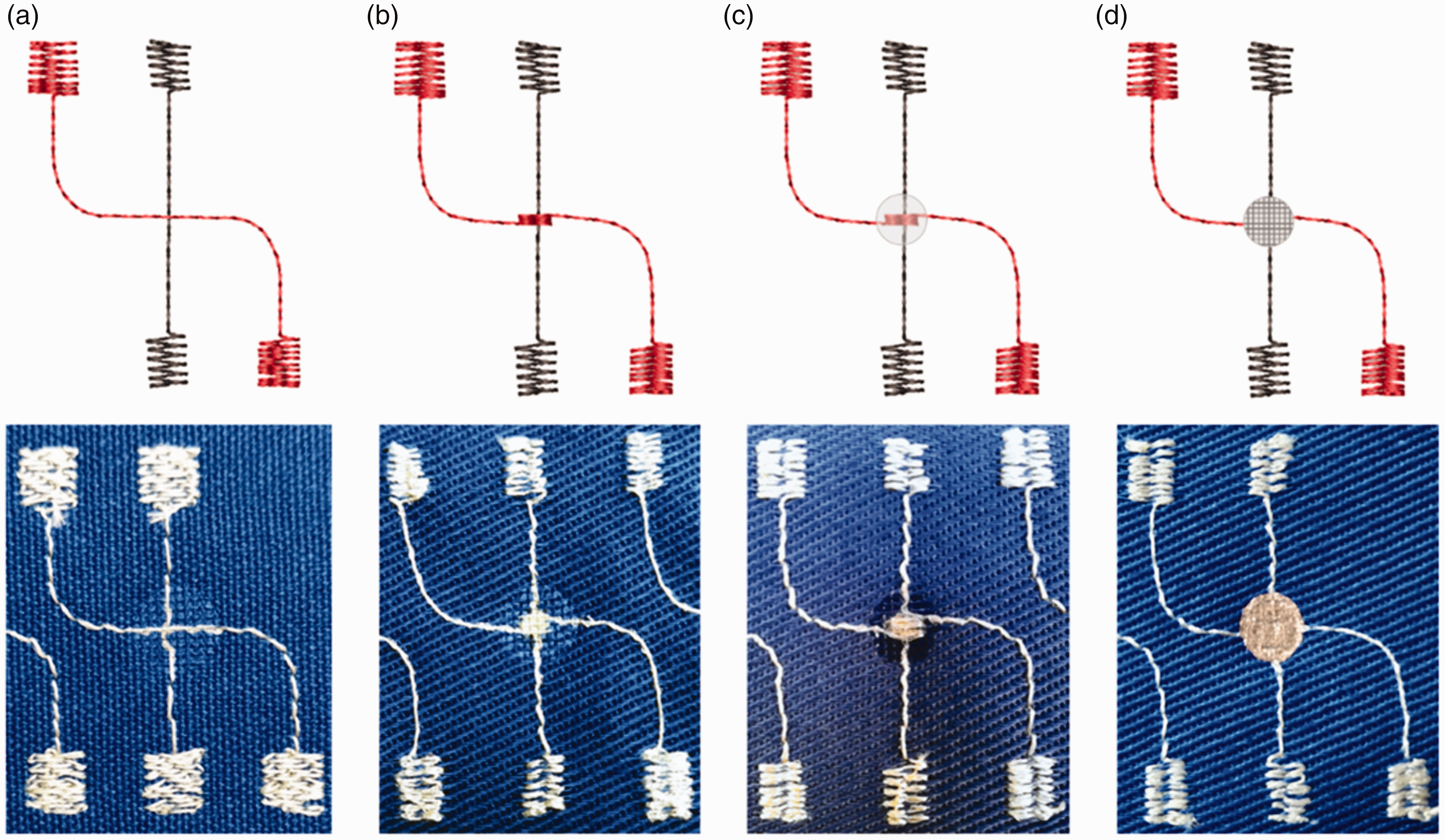
Design of patterns and ultrasonically welded crossing of test samples with a (a) plane crossing, (b) embroidered pad, (c) embroidered pad and non-conductive thermoplastic polyurethane (TPU) insert material, and (d) embroidered pad, conductive nonwoven, and non-conductive TPU insert material.
Design and assessment of welding tools
All interconnection experiments within the research were carried out with an ECO iSONIC ultrasonic welding machine from SONOTRONIC with a 35 kHz/800 W generator. A welding tool, the sonotrode, is used to transfer the vibration energy from the welding machine to a workpiece and to apply the pressing force of the machine to the workpiece at the same time. The design of the sonotrode and its topography are very important for the welding result. Within this research, three different types of sonotrodes with different surfaces topographies made of titanium alloy have been developed, manufactured, and tested: a flat surface, a rippled surface with a pyramidal surface, and a frustum surface. In the case of ultrasonic welding using a flat surface sonotrode, the melted material was accumulated in the crossing contact area and the hybrid conductive yarns were not sufficiently pressed and fixed together; thus, their electrical contact was not reliable enough (depicted in Figure 6(a)). The sonotrodes with a rippled surfaces allow excess molten material to flow into the sonotrode cavities and provide tighter contact among the microwires of the ultrasonically welded hybrid conductive yarns. However, the pyramidal type of sonotrode (depicted in Figure 6(b)) was not sufficiently gentle for the hybrid conductive yarn. The microwires were broken or the silver coating of the metallized polymer threads was rubbed off by the sharp edges of the sonotrode or burned by the small horn structures, as more energy is emitted per area. The tests showed the best results for the frustum surface of sonotrode (depicted in Figure 6(c)). Therefore, all subsequent samples were welded using this sonotrode. The diameter of the selected sonotrode is 8 mm. A total of 76 frustum structures are evenly distributed on the horn surface. The design of the individual frustum structures is shown in Figure 7.
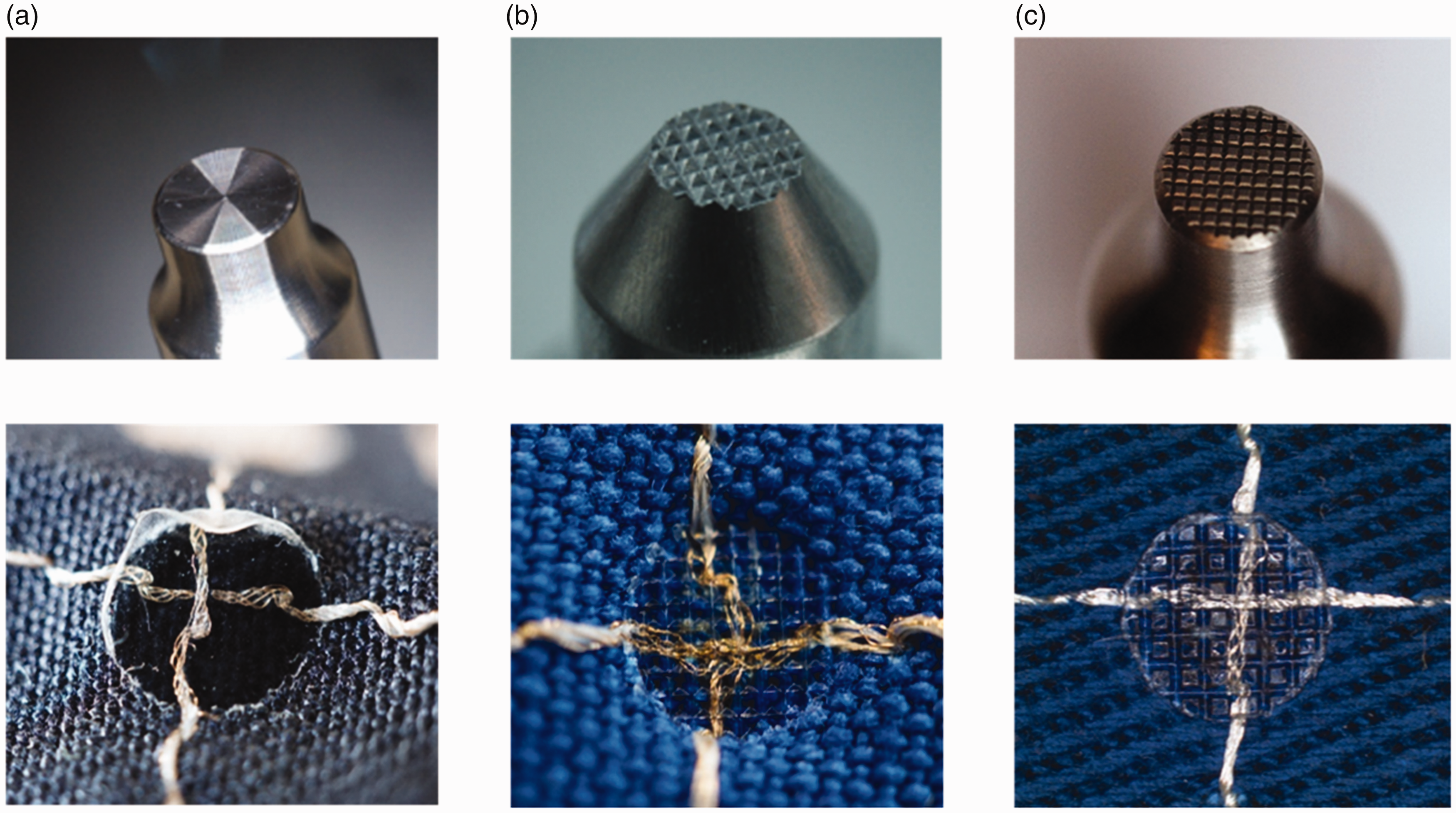
Overview of test sonotrodes and samples realized by individual types: (a) flat surface; (b) rippled surface with a pyramidal tip and (c) frustum sonotrode.
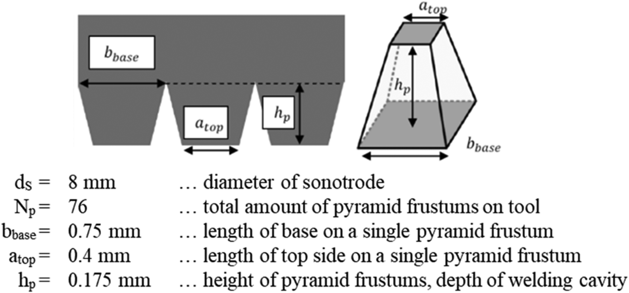
Design of the frustum sonotrode.
The second part of the ultrasonic machine that comes into contact with the workpiece is the anvil. The anvil is the counterpart to the sonotrode and is used to position the workpiece and to damp the vibrational energy by selecting the appropriate material, for example, cast resins or silicones. In this study, a planar hard anvil made of aluminum was used as experiments with soft materials, such as silicone-coated cushion pads, did not lead to reproducible results.
Ultrasonic welding interconnection process
The proposed interconnection process can be shortly described as following: firstly, a thermoplastic material is either already part of the joining materials, for example as a yarn insulation layer, as a filament, or as an additional applied film to the contact surface before the joining process. When the ultrasonic welding process starts, the sonotrode moves onto the contact surface and the vibrations begin. Due to the applied process force, the conductive contact materials approach each other, while at the same time the thermoplastic material becomes more viscous and thus begins to soften and flow. After switching off the ultrasound, the thermoplastic quickly solidifies again. During the cooling phase, the process pressure continues to be exerted into the welding zone, which leads to better adhesion of the materials. An additional effect is that the textile-integrated conductors are completely embedded in the thermoplastic matrix, creating a mechanical and electrical interconnection within the same process.
In our test setup, the PES fibers as a thermoplastic part of the hybrid conductive embroidered yarn are melted in the crossing area during the ultrasonic welding process. The conductive microwires of the hybrid yarn are pressed by the welding force; thus, an electrical interconnection is created. The melted polymer fibers of the yarn solidify again after the ultrasonic welding process; therefore, the conductive interconnection of the hybrid yarns is fixed (process depicted in Figure 8). When the volume of melted polymer fibers is low, thermoplastic insert material can be added to the crossing area of the yarns. The additional insert material then better fixes the joint and contributes to its higher mechanical and environmental resistance.
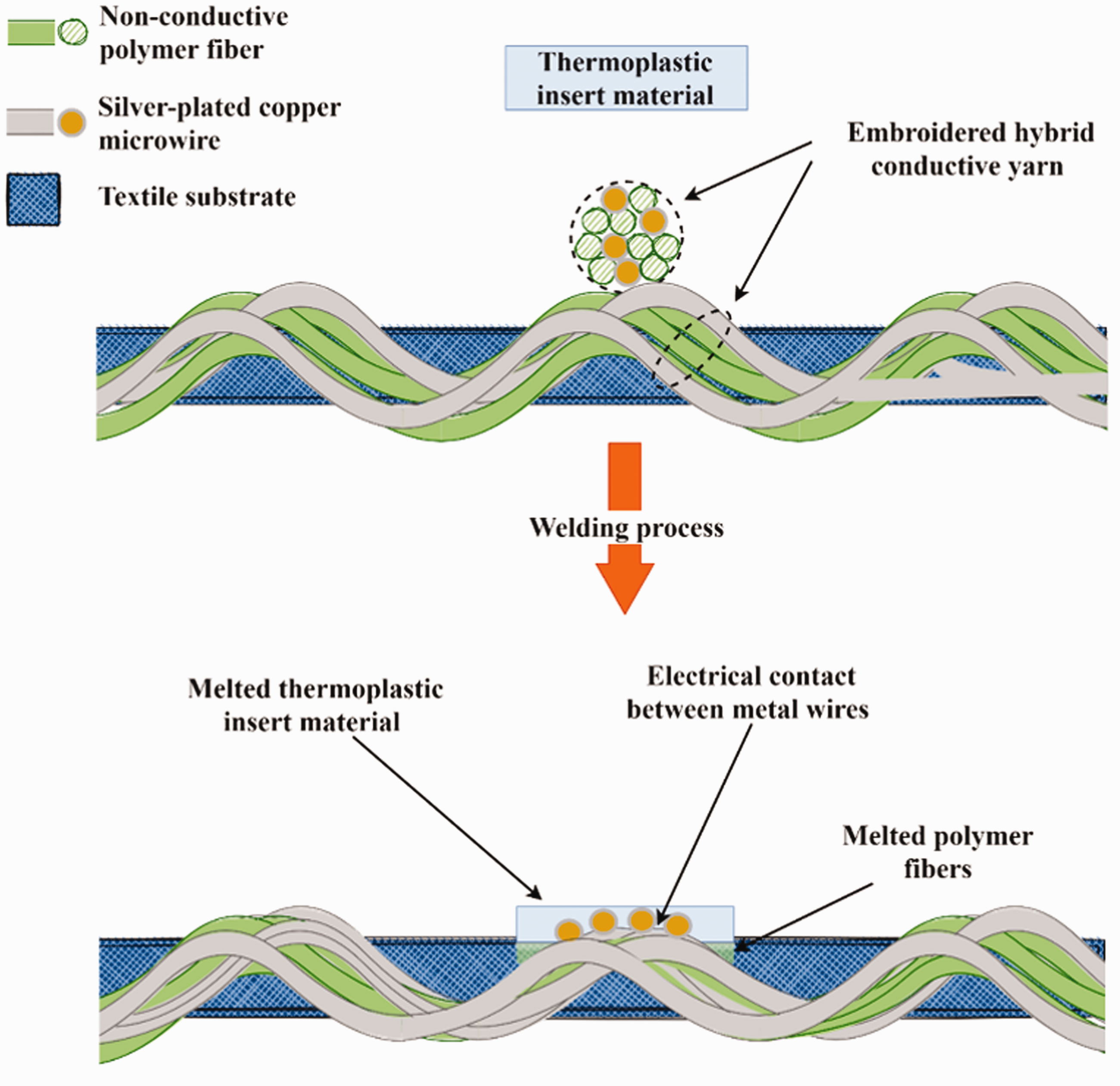
Illustration of the ultrasonic welding process for interconnecting embroidered conductive yarns.
Design of a full factorial test plan
To investigate the optimal process parameters for different material combinations and the influence of the relevant factors on the contact results, a full factorial test plan was created. Figure 9 depicts the parameter diagram developed for this test setup. The signal factors and the limits of the control factors were found in preliminary studies within a test range for welding energy: 1–100 J; force: 100–400 N; and amplitude: 18–36 µm. For the main tests, the following signal factors were defined as fixed: the sonotrode with a frustum-shaped welding surface; 35 kHz, 800 W ultrasound generator; hybrid conductive yarns containing four silver-plated copper wires (Y05) or eight silver-plated copper wires (Y08); cotton substrate No. 3; TPU film (Platilon® 4201 AU100) as a non-conductive adhesive; Shieldex® Bonn as an optional conductive insert; embroidery layout with a pad structure at the intersection of two crossing hybrid yarns and 5 s curing time with a curing force that equals the set welding force.
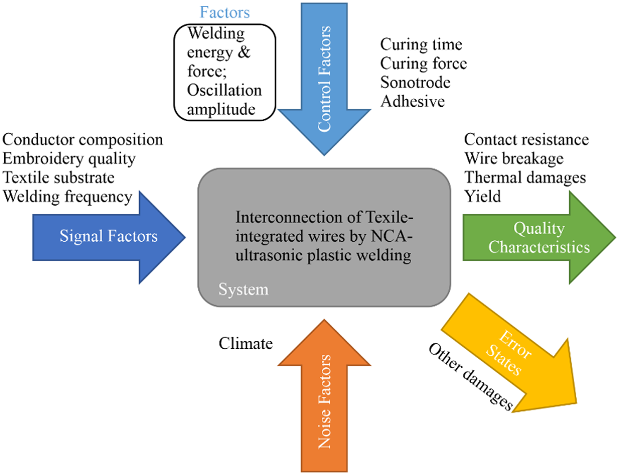
Parameter diagram of the non-conductive adhesive (NCA) ultrasonic-welded interconnection process.
By empirical experiments, the lower and upper limits of the control factors could be determined in advance. The preliminary tests showed that hybrid conductive yarns could only be welded with low mechanical loads. At higher welding forces and amplitudes, fractures in the microwires could be identified as the cause of the contact failures. In contrast, the process window for choosing the welding energy is significantly larger. It should be noted, however, that if the energy is set too low, the contact materials are not heated to the point of melting, or if the energy is set too high, the material can be thermally damaged or even decomposed. Table 6 lists the resulting range of process parameters of the final test plan.
Selected parameters of the full factorial test plan
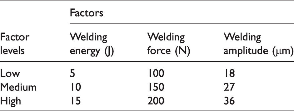
Each of the three main factors is tested on three levels, resulting in 27 combinations. The process parameters were tested and evaluated for four material combinations (two conductor materials and two adhesives each). A general overview of the number of tests for each material combination is given in Table 7.
Number of trials for the test plan
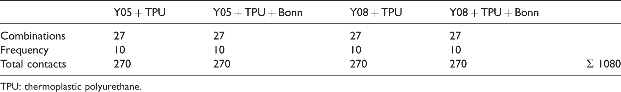
TPU: thermoplastic polyurethane.
Design of test vehicles for the electrical characterization of samples
The realized interconnections of hybrid conductive yarns were characterized electrically by four-wire resistance measurement. The electrical resistance was measured by a four-wire method using a Keithley 2700 multimeter with a 10-channel multiplexer. As depicted in Figure 10, the test current I is applied from the force terminal to the ultrasonically welded contact and the sense probe detects the voltage drop developed. Instead of the two-wire conventional method, the test current does not flow through the same terminal where the voltage drop is detected; hence, this method eliminates the resistance of measuring probes and the resistance of conductive traces on the textile as well. Special contact fixtures with spring probes and magnetic fixation were developed for the purpose of contacting the test objects. For mass measurement with a multiplexer, a set with 20 contact probes was created; two of them are depicted in Figure 11. Each ultrasonically welded joint was later measured by the four-wire method three times.
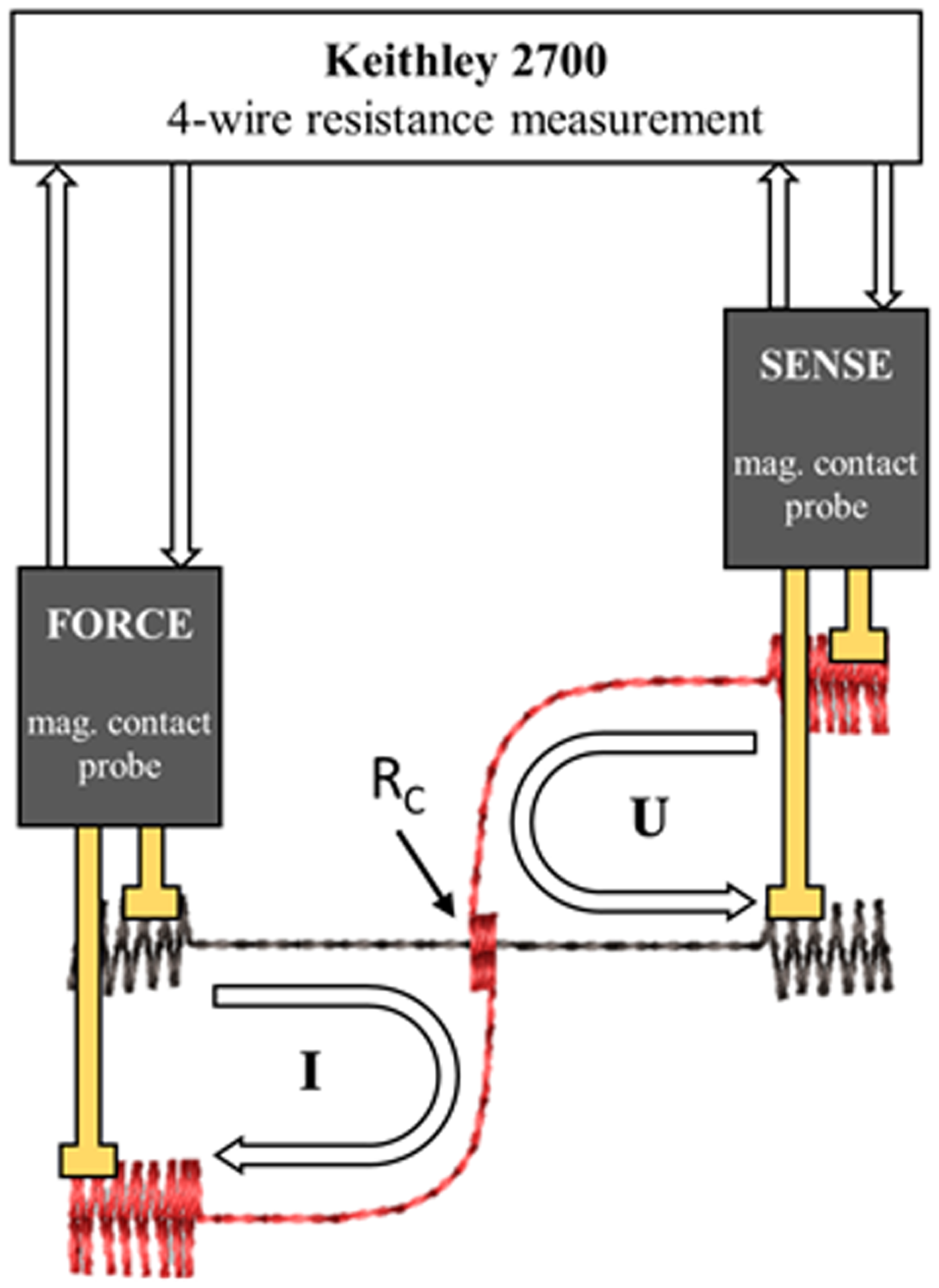
Principle of four-wire resistance measurement.
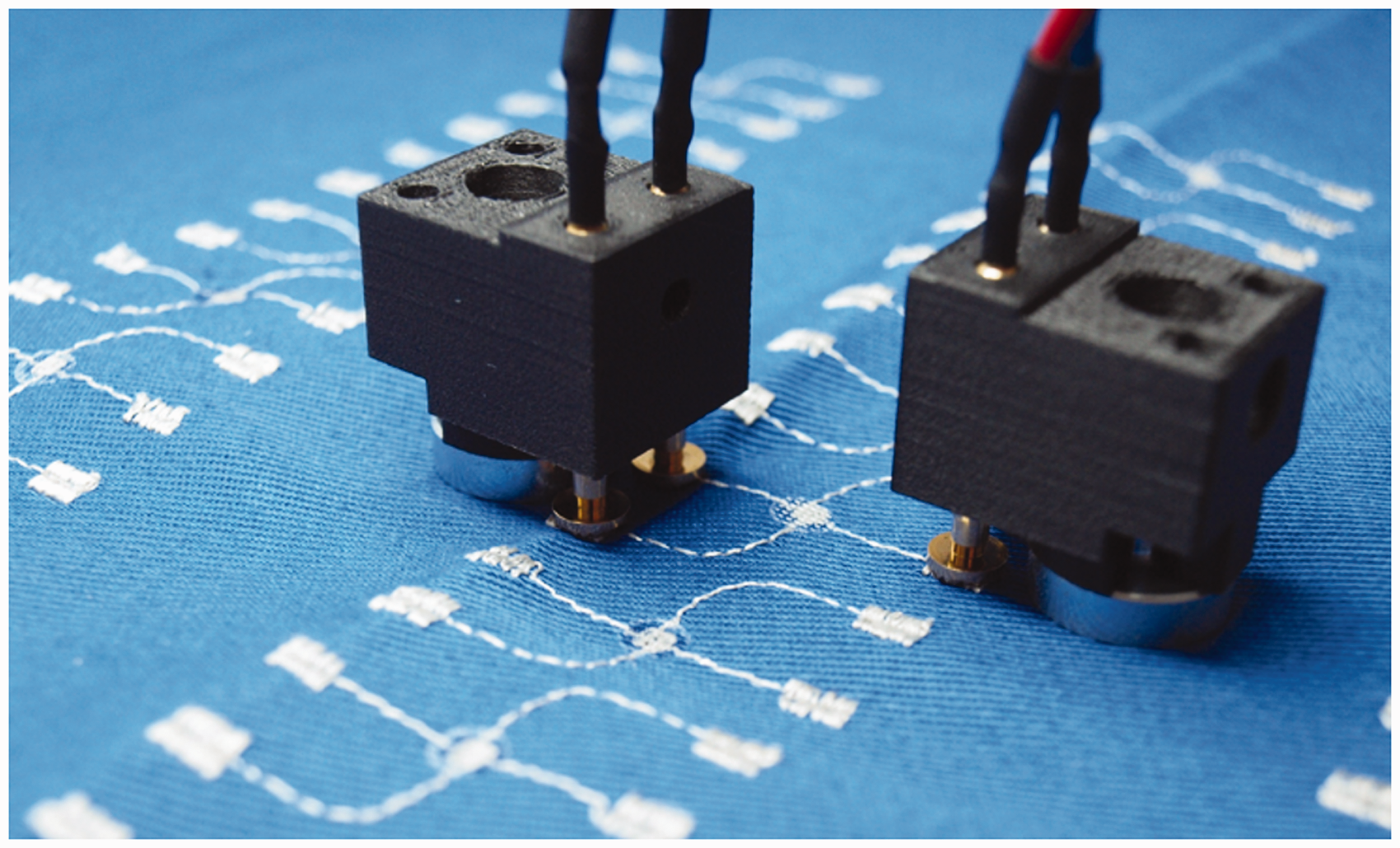
Customized contact probes with spring needles and magnetic fixation developed for contacting test objects.
Aging tests of welded hybrid yarns
After the initial contact resistance measurements, the welded samples were gradually exposed to dry heat, temperature shocks, bend, and finally washing tests. In the first step, the samples were subjected to a dry heat test at 85°C for 120 h in a climatic chamber according to EN 60068-2-2. 41 The PES yarn material and TPU insert are melted during the ultrasonic process and, subsequently, they work as a fixation of electrical contact. The fixation ability can decrease by the high-temperature exposition due to polymer relaxation and different material coefficients of thermal expansion (CTEs) and, because of this fact, the electrical resistance can increase or fail. The second test was performed by thermal shocks in accordance with EN 60068-2-14 42 in the climate chamber, where the samples were kept at –20°C for 15 min and then moved to the upper chamber within 10 s, where the temperature was set to +85°C. Samples also remained in this chamber for 15 min. This cycle was repeated, in total 200 times. The thermal shock test has an impact on the thermo-mechanical features of the individual materials. The polymers of hybrid yarns, TPU insert materials, and textile substrates can become brittle by thermal shock exposition as well, as delamination can occur due to the different CTEs. In the third step, the samples were subjected to 2000 cycles of the bend test. The mechanical stress during the bend cycles can influence the interconnection of welded yarns and increase the electrical resistance. The last test was focused on washing and drying following the standard EN ISO 6330: 2012 – Domestic washing and drying procedures for textile testing. So far, there are no standardized procedures for washing tests of e-textiles and no protocols for the comparable evaluation of the washability of tested products. Despite its disadvantages, the standard mentioned has currently prevailed and is used by many, at least until a special washing test for e-textiles is developed. 43 The ultrasonically welded contacts are exposed to the washing factors of time, temperature, and mechanical action. Test samples were placed in protective laundry bags before washing. In the wash test, the samples were washed at the temperature of 40°C, 400 rpm, detergent: type 3 (ECE), detergent quantity: 20 g, the total weight of samples and accompanying woven fabrics: 2 kg. Subsequently, the samples were dried in an automatic dryer at 60°C for 60 min. In total, five washing and drying cycles were done. A flowchart of the test procedure of the samples is depicted in Figure 12.

Flowchart of the test procedure.
Experimental results
Optical analysis of the hybrid conductive yarn interconnection
In the optical analysis, contact formation as well as causes of failures could be detected. Figure 13 shows examples of X-ray images for both a successful (a) and a failed welded joint approach (b), where the individual microwires have been broken by the ultrasonic process.
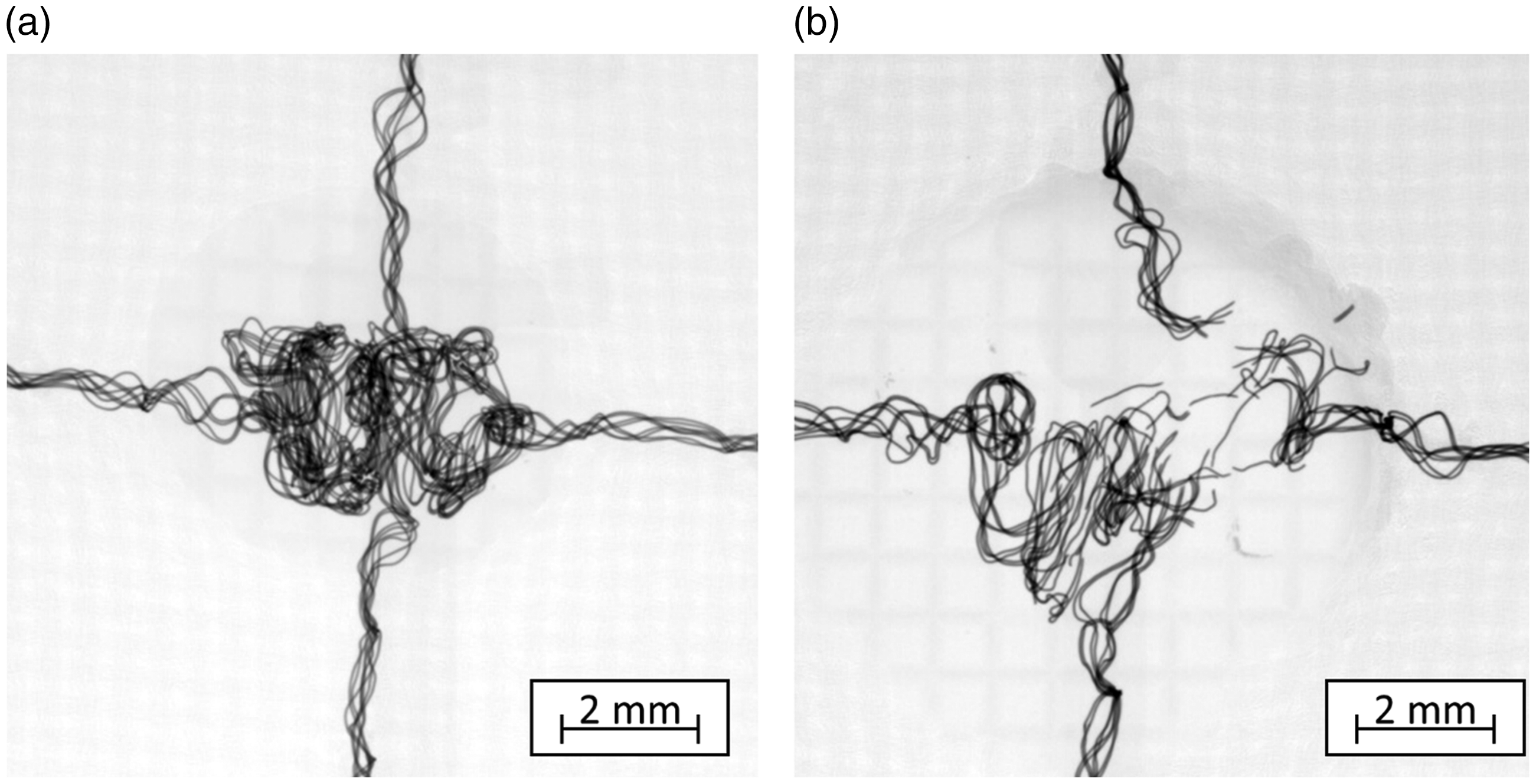
X-ray images of (a) a welded, low-ohmic interconnection and (b) a broken sample after welding.
A typical example of the ultrasonically welded interconnection of two hybrid yarns with an embroidered pad is depicted in Figure 14. It represents a micro-computed tomography (micro-CT) X-ray image done by GE Phoenix v|tome|x s. The picture shows the crossing of two hybrid yarns containing eight Cu/Ag microwires, where the interconnection of yarns is multiplied by an embroidered pad. The used welding parameters for the sample were energy 10 J, force 100 N, and amplitude 18 µm. The interconnection was encapsulated with a non-conductive TPU insert.
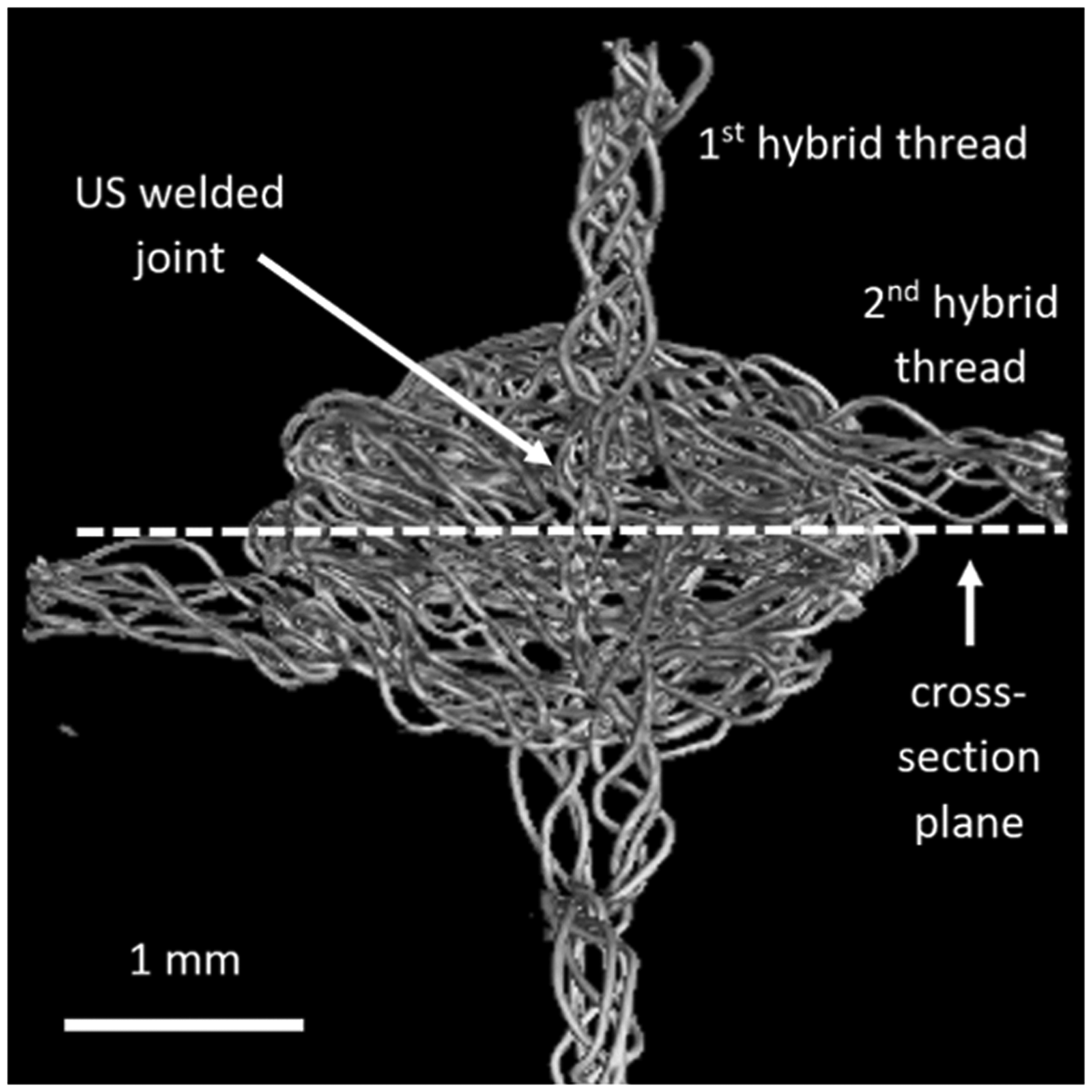
Micro-computed tomography X-ray image of an ultrasonically (US) welded interconnection of two Cu/Ag-based hybrid yarns with a depicted plane for the materialographic cross-section.
Figures 15 and 16 depict materialographic cross-sections of the ultrasonic welding interconnection indicated with the dashed line from Figure 14. The cross-section was observed using scanning electron microscope Phenom PRO X and stereomicroscope Olympus SZX10. Cross-section figures prove that individual microwires of hybrid yarns are getting into close mechanical contact during the welding process. It is also obvious from Figure 15 that immediately after the welding, the solidified thermoplastic polymers (TPU and PES) fix microwires in tight contact and create a stable electrical and mechanical interconnection. The solidified thermoplastic polymer film in the welded area well penetrates the textile substrate, is homogeneous, and without any voids, pores, or cracks. The interconnection of microwires contains no residues of thermoplastic material, as depicted in Figure 16.
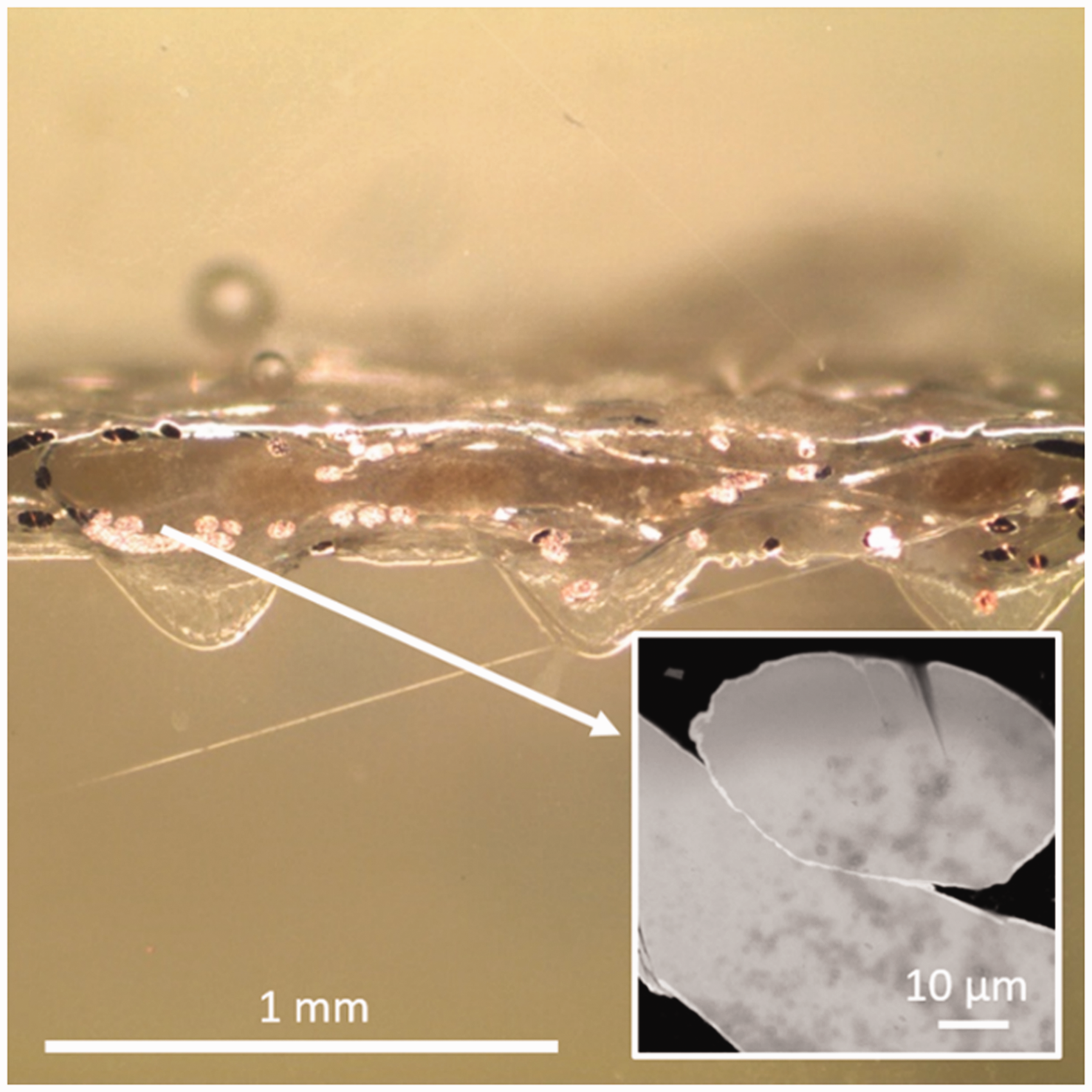
Cross-section of an ultrasonically welded joint of two hybrid conductive yarns – stereomicroscope Olympus SZX109 and scanning electron microscope Phenom PRO X.
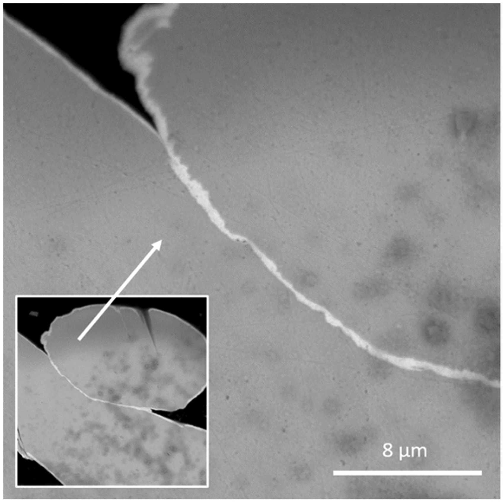
Cross-section of an ultrasonically welded joint of two hybrid conductive yarns – detail of the join of two Ag-plated Cu microwires – scanning electron microscope Phenom PRO X.
Electrical analysis of the hybrid conductive yarn interconnection
When it comes to electrical characterization, the interconnections must be part of an electric circuit and are considered electrical resistances. The permissible value of the electrical contact resistance depends on the electronic system and desired application and is therefore not generally defined. 44 However, the lower the contact resistance, the better the signal quality and the lower the heat generation. The increase in contact resistance, for example after reliability tests, is also a good indicator of contact fatigue, which can lead to failure of the electronic system over time. In our study, a break in the electrical connection or an increase in resistance by 150% is defined as a contact fault. 45
After carrying out the welding tests according to the full factorial test plan, all samples were examined by means of four-point electrical resistance measurement. It turned out that the results can be divided into two groups. The first group contains all successfully contacted samples with a low contact resistance of a few milliohms. The determined contact resistances were in the range of 1–10 mΩ, with an accumulation of the measured values between 1 and 2 mΩ. Thus, a failure is defined when a contact resistance exceeds the value of 25 mΩ (10 mΩ initial value plus 150% increase of 15 mΩ) or a sample has no electrical contact after welding. In the second group, no electrical contact could be measured and all the corresponding samples show a wire break in the welding area in the X-ray inspection. Due to the simple classification of the measurement results into contact realization or not, further evaluations of the tests are carried out based on the process yield or failure rate.
Statistical evaluations were carried out in order to analyze the influence of the process parameters on the error rate. The following graphical evaluations of the test results were carried out with the statistical software JMP® 15 from the SAS Institute. Figure 17 depicts a scatter plot including a simple linear regression line of all main factors related to the failure rate. Figure 18 depicts the indices of importance of the main effects as well as the total effects and is used to estimate the influence of the effects on the failure rate. The factors in the bar charts have been arranged according to their order in relation to the total effect significance.
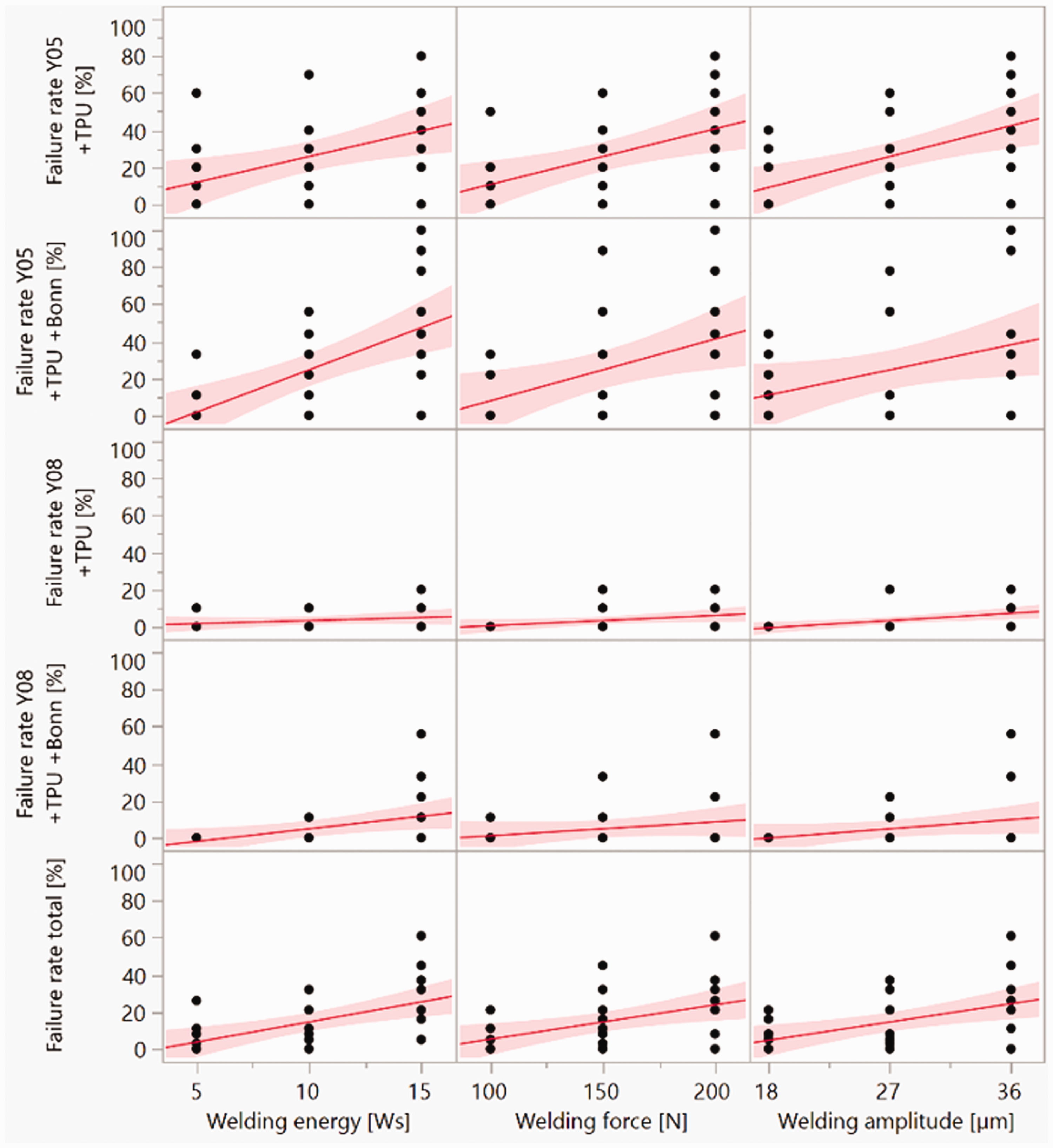
Scatter plots of experiments. TPU: thermoplastic polyurethane.
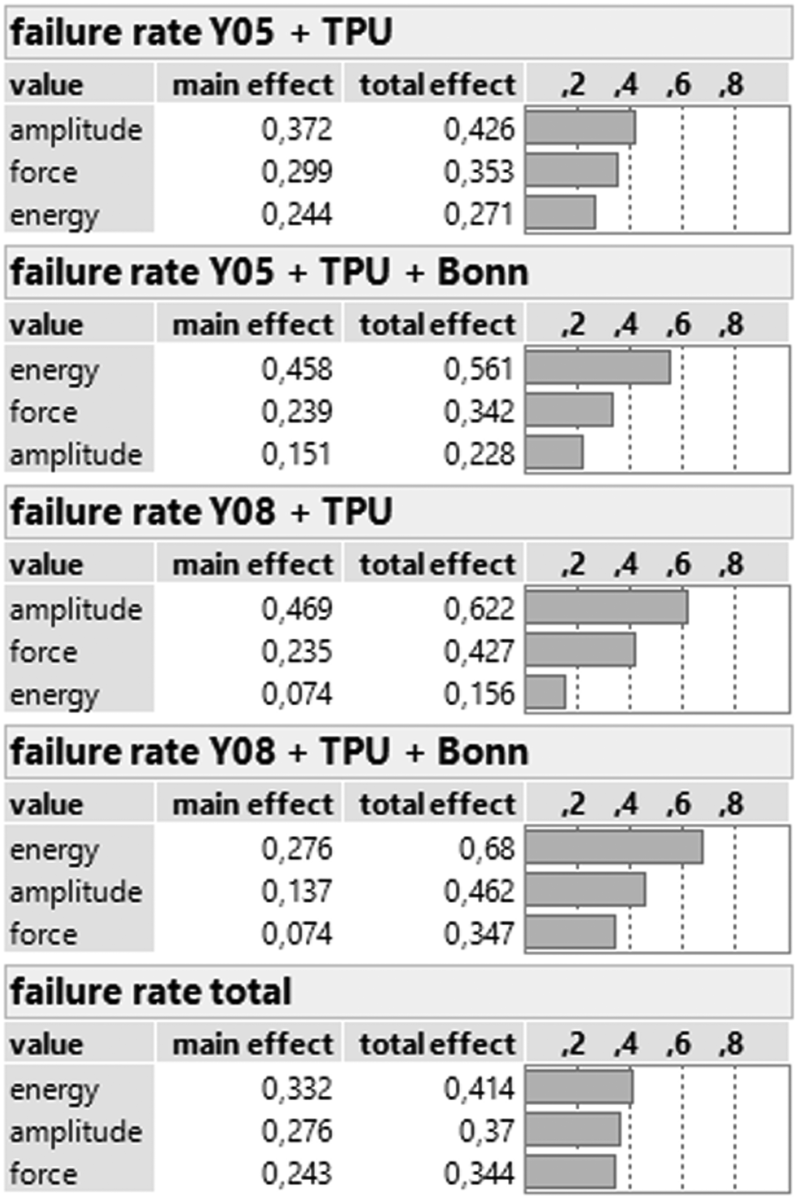
Effect charts of experiments. TPU: thermoplastic polyurethane.
An interaction occurs when the effect of one welding factor depends on the level of another factor. Possible interactions can be illustrated by means of an interaction diagram. Parallel lines in an interaction diagram indicate that there is no interaction. The greater the difference in slope between the lines, the greater the degree of interaction. However, it cannot be determined from the interaction diagram whether the interaction is statistically significant. Figure 19 depicts the two-way interaction diagrams, which show the positive correlation effects for each sample.
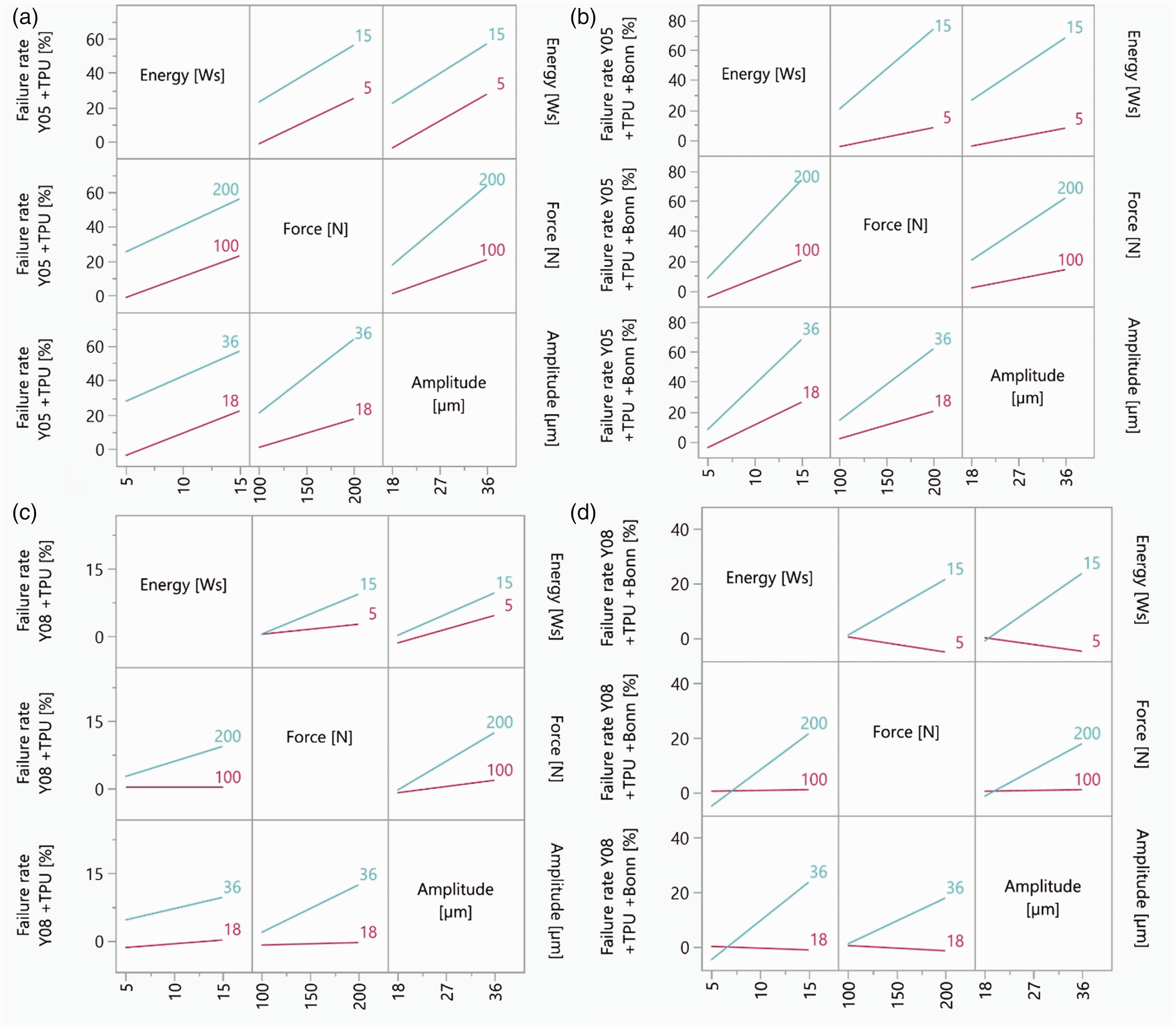
Correlation effects for (a) Y05 + thermoplastic polyurethane (TPU), (b) Y05 + TPU + Bonn, (c) Y08 + TPU, and (d) Y08 + TPU + Bonn.
For a better overview, the yield and factor analysis of the interconnection tests is briefly summarized in Table 8.
Evaluation of the test results
TPU: thermoplastic polyurethane.
It is clear from the factor analysis that lower contact resistance and higher yield was observed in the case of using yarn Y08 containing eight Cu/Ag microwires. This is due to the higher number of microwires in the yarn structure and hence a higher number of micro contacts are formed at the weld site. Based on these results, this yarn (Y08) was chosen for further testing.
The statistical analysis has shown that ultrasonic plastic welding of conductive hybrid yarns with TPU film achieves very good yield (up to 100%) at low mechanical parameters. Welding with an additional metallized nonwoven dampens the mechanical effects but limits the introducible energy. A process parameter window could be determined for each combination of materials with which an excellent yield (≤100%) can be realized at low contact resistances Rc (1 mΩ ≥ Rc ≤10 mΩ). The significant main and interaction effects leading to electrical contact failure are expected to be material dependent and could also be determined for each material. However, the results show that the best welded interconnections with low-ohmic values of contact resistance and non-visible damage of microwires were realized with Y08 yarns and TPU encapsulation welded with energy ranging from 5 to 10 J, force of 100 N, and 18 µm oscillation amplitude.
Influence of reliability tests on the welded interconnection
Based on the yield analysis and low failure rate, the samples embroidered with Y08 hybrid conductive yarn were further tested for reliability. Yield analysis was realized according to the electrical resistance of the interconnection right after implementation. However, this is not the guarantee of interconnection reliability after the aging tests. Hence, the scale of the welding parameters was extended. The investigated interconnections were realized with 10 J welding energy, welding force from 100 to 200 N and amplitude of lengthwise oscillation from 18 to 36 µm.
A comparison of the electrical resistance of the realized interconnection after manufacturing and reliability tests is shown in Figure 20 (welded with TPU insert) and Figure 21 (welded with TPU insert and Shieldex® Bonn). The electrical resistance of the realized samples is influenced by the welding amplitude and force, especially for samples without the conductive insert Shieldex® Bonn. The lower welding amplitude and force respectively mean less (i) mechanical stress during the welding, (ii) disruption of the silver-plated surface of the microwires, and (iii) cut-off microwires. Similarly important are the insert materials in the welding area, where more materials also imply less mechanical stress to the hybrid conductive yarn using the same welding parameters and lower interconnection resistance. On the other hand, it also means lower energy transfer to the hybrid yarn crossing and less melted thermoplastic material close to the yarns, which implies less reliability of the welding process.
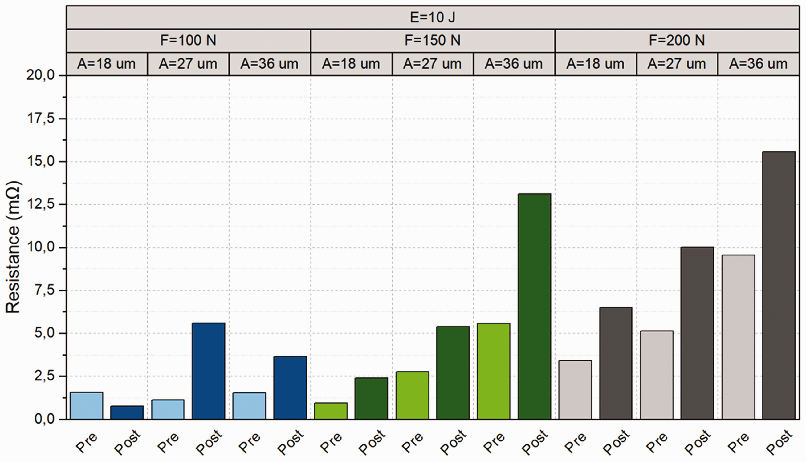
The electrical resistance of hybrid conductive yarn Y08 interconnection with thermoplastic polyurethane insert welded by 10 J energy.
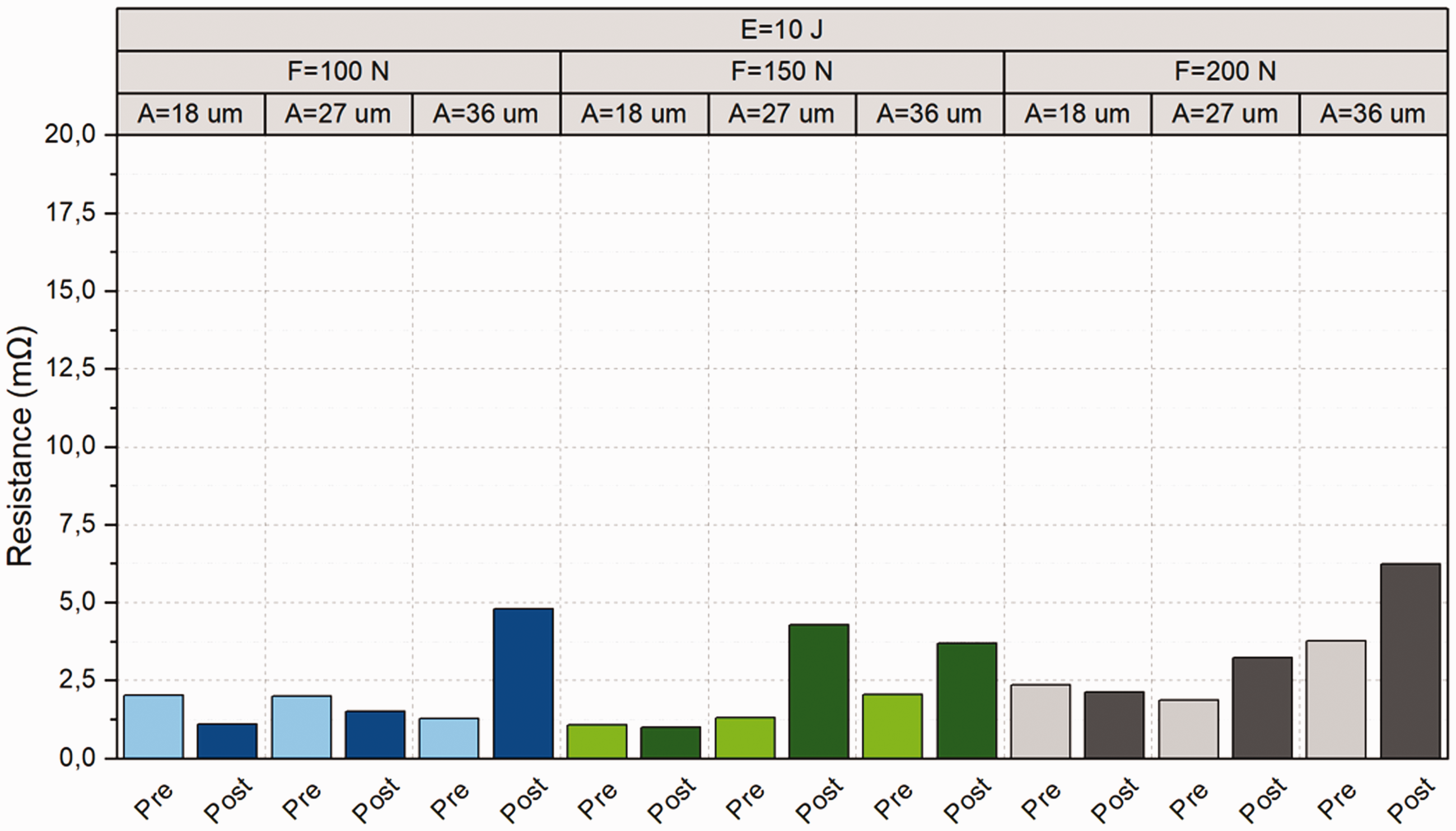
The electrical resistance of hybrid conductive yarns Y08 interconnection with Shieldex® Bonn (Ag-coated nonwoven) and thermoplastic polyurethane insert welded by 10 J energy.
Generally, the electrical resistance after tests grows as much as 150%, especially with rising welding amplitude and for the variant only with the TPU insert, but stays under the 25 mΩ threshold value. The smallest resistance changes after the aging procedure, which indicate the best stability, were observed for samples welded by the lowest 18 µm amplitude, and with TPU and nonwoven Shieldex® Bonn insert. The resistances of these samples before and after tests differ in the tenths of milliohms, which is the same as the resolution abilities of the Keithley K2700 multimeter. Nevertheless, the absolute electrical resistance after tests did not exceed 16 mΩ, which means 0.6% in comparison with the electrical resistance of Y08 hybrid conductive yarn per meter.
Conclusion
A new interconnection method for the realization of stable electrical connections of hybrid conductive yarns in the field of e-textiles based on ultrasonic plastic welding was proposed, tested, and investigated. It has been proved that very stable electrical interconnections of hybrid conductive yarns consisting of metal microwires and PES filaments can be realized by ultrasonic plastic welding. The best results in terms of yield, contact resistance, and stability of electrical interconnection during the mechanical and environmental loads were achieved for samples with the capability of multiple joint formation. Multiple joints can be easily formed by the embroidering of the pad from one of the crossing hybrid yarns. The best results were obtained for the hybrid conductive yarn containing eight microwires in combination with a cotton-based woven substrate and a pattern with the embroidered pad. The mechanical durability and long-term stability of ultrasonically welded electrical interconnection can be further strengthened by a non-conductive adhesive (TPU) or conductive (Ag-coated nonwoven) insert. The statistical analysis has shown that ultrasonic plastic welding of hybrid conductive yarns with TPU inserts achieves a very good yield (up to 100%) at low mechanical process parameters. The best results were achieved for the following process parameters: welding energy 5–10 J, force 100 N, and amplitude of the sonotrode oscillation 18 µm. The median value of contact resistance of samples welded using such parameters is below 2.5 mΩ even after the mechanical and environmental reliability tests. The X-ray, micro-CT, and scanning electron microscopy (SEM) examinations confirmed that individual microwires of hybrid yarns come into close mechanical contact during the welding process and that, after welding, the solidified thermoplastic polymer fixes the microwires in close contact, thus creating an electrical and mechanical interconnection.
The main advantage of the developed ultrasonic welding interconnection process is that the electrical contact is created simultaneously together with its mechanical fixation and encapsulation in one single manufacturing step. The realization of interconnection together with encapsulation is very fast (within seconds), reliable, and mechanically stable. The promising results and advantages of the technology offer the industry a cost-effective, fast, and scalable process alternative to soldering textile-integrated conductors. Therefore, new experiments to interconnect further developed conductive hybrid yarns by ultrasonic welding are planned; in particular, thermoplastically coated conductors with and without the addition of Ag-coated filaments in the hybrid yarns, which could optimize the contact realization and reliability through their ductility.
Footnotes
Acknowledgements
The authors would like to thank for VÚB a.s. for providing the conductive hybrid yarn as well as Deutscher Verband für Schweißen und verwandte Verfahren e.V., Forschungskuratorium Textil e.V., CLUTEX – Klastr Technické textilie, o.s., and the projects user committees for their support during the research phase.
Declaration of conflicting interests
The author(s) declared no potential conflicts of interest with respect to the research, authorship, and/or publication of this article.
Funding
The author(s) disclosed receipt of the following financial support for the research, authorship, and/or publication of this article: The IGF research project (278 DE) of the Research Association Forschungskuratorium Textil e.V., Reinhardtstraße 14-16, 10117 Berlin was funded by the AiF within the framework of the program for the promotion of “Industrielle Gemeinschaftsforschung” (IGF) with funds from the Federal Ministry of Economics and Climate Protection (BMWK) based on a resolution of the German Bundestag.