
Abstract
Digital twins have emerged as highly valuable tools for model-based planning, simulation and optimization over the last couple of years, thereby demonstrating considerable potential for application within the construction industry. The introduction of building information modeling (BIM) has effectively established a standardized approach to representing building models. However, in practice, many of these models currently exhibit limitations as to their quality, specifically concerning the level of detail they encompass. In addition, BIM models too often are locked inside a specific vendor’s tool which readily implies a lack of platform independence, or interoperability, which, however, is essential for facilitating single and regressive, i.e., after a design change, model-based building performance simulations. Model-based engineering has effectively addressed comparable challenges within the domain of software engineering over the past decades by facilitating the integration and interoperability of models from various origins, by capitalizing on model-based tool integration. Prompted by these advantages, this study introduces a model-based tool environment that addresses the aforesaid challenges concerning BIM model quality and interoperability. Taking advantage of our proposed model-based tool environment, we implement an agile, continuous planning process for regressive, model-based building performance simulations, thereby enhancing building energy efficiency planning.
Keywords
1. Introduction
Digital twins (DTs) describe virtual replicas of cyber-physical systems (CPSs) that are characterized by Grieves et al. 1 :
a virtual instance, i.e., the assemblage of system, simulation, optimization, and operating models which together replicate the CPS,
a physical (or product) instance, i.e., the CPS, and
interchanged data and connections, i.e., bidirectional communication, or twinning, between the virtual and physical instance, respectively.
As depicted in Figure 1, DTs may manifest at three different levels, viz. as a digital model, shadow, or twin depending on the degree of automated interchange of data. 2 A digital model simply describes a virtual representation, a digital shadow is a digital model augmented with real-time data from the physical instance, and finally, a DT in addition allows for controlling the physical instance from the virtual instance, respectively (cf. bidirectional data exchange).
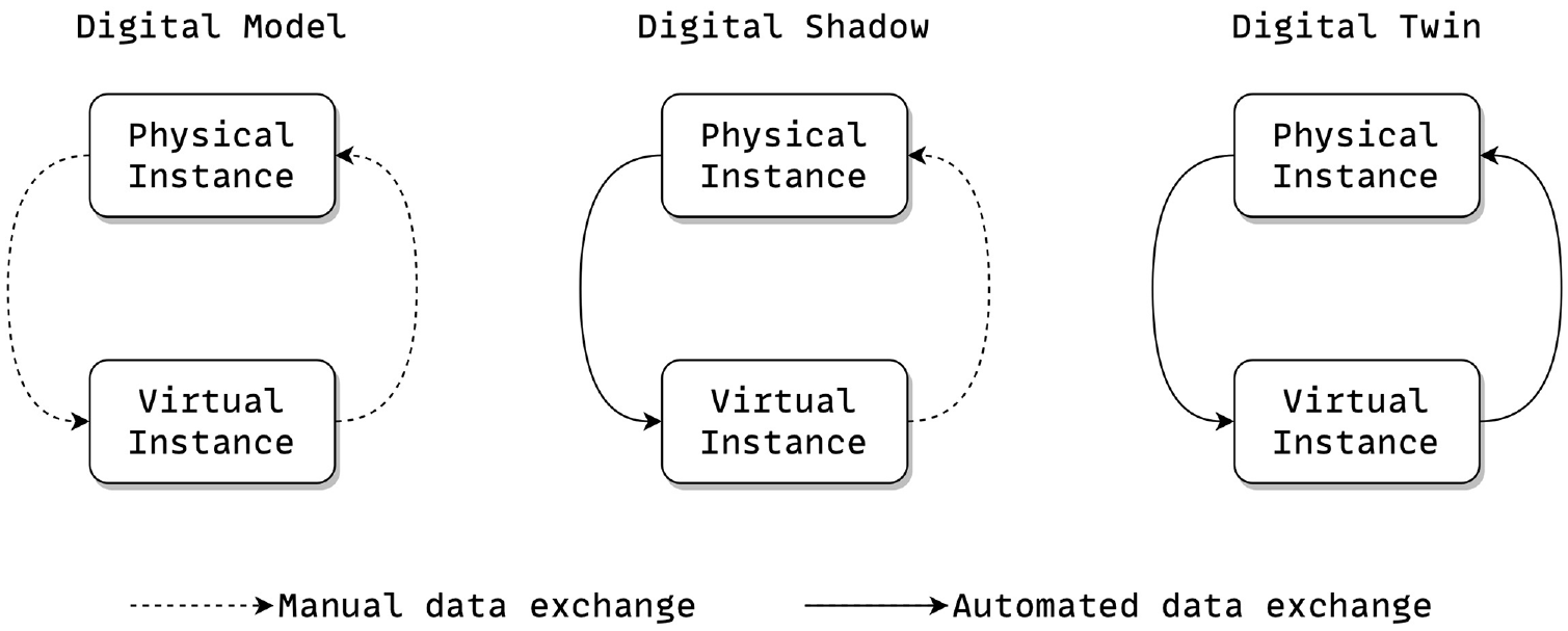
Types of DTs given the automation of data exchange. 2
The architecture, engineering, construction, and operation (AECO) domain has shown increased interest in exploiting DTs for the planning and simulation of buildings during early planning phases, and subsequently for continuous optimization of building operations after construction.3–5 Especially during early planning phases, regressive (cf. regression testing in software engineering 6 ) and iterative building simulations to optimize a building’s shape, cubature, orientation, and glazing can contribute substantially to increasing energy efficiency, but also climate resilience and living comfort in winter and summer. 7
The integration of DTs and building energy modeling (BEM), i.e., the process of simulating and analyzing the energy performance of a building using digital models, allows for the creation of a dynamic digital representation of a building that includes energy-related data. This integrated approach enables real-time monitoring of energy performance, prediction of energy consumption, identification of energy-saving opportunities, and optimization of the building and its built-in building automation systems (BASs). 8 A DT for BEM is a virtual replica or representation of a building that incorporates sensor and BAS data, and environmental conditions to create an accurate digital model. It enables building owners, operators, and building physicists to simulate, analyze, predict, and optimize energy usage, occupant comfort, and overall building performance. 4 On a larger scale, buildings’ energy performance occupies a major role in achieving the United Nation’s (UN) Sustainable Development Goals (SDGs) 9 as postulated by the European’s (EU) Green Deal. 10 Currently, the EU buildings sector contributes around 35% of greenhouse gases (GHGs) by energy-related emissions. 11 These result from both the direct use of fossil fuels in buildings (e.g., oil and gas for heating boilers) and from the production of electricity and heat for use in buildings. Improving the energy efficiency of buildings by successfully applying BEM would allow for a substantial reduction of the GHG footprint of buildings.
A DT for BEM capitalizes on a building information modeling (BIM) model that comprises a building’s geometry, construction materials, HVAC (Heating, Ventilation, and Air Conditioning) systems, lighting and shading installations, and occupancy patterns, for performing accurate and regressive, i.e., repeated after a design change, model-based simulations. Whereas with BIM, a standard for the representation of building models has been established; these models, however, often lack the necessary quality, e.g., level of detail, and platform independence, or interoperability, to be employed for BEM in an integrated BIM2BEM workflow. This lack of model federation and consequent tool interoperability which epitomizes most prominently in media disruptions at the model level currently stymies holistic building planning and model-based simulation using DTs.12–15 This lack of tool integration, in turn, requires the establishment of dedicated model mappers to connect BIM and BEM tools. Currently, this is done on a 1:1 basis, i.e., a distinct mapper for each BIM and BEM tool combination 14 (cf. the Passive House Planning Tool Package (PHPP) 16 ) is employed. Ideally, however, a 1:n or m:n approach using a tool-independent mapper that allows for easy customization toward different BIM and BEM modeling formalisms is established to tackle current, prevalent issues in BIM2BEM, viz.:
costly and manual re-modeling of BEM models, resulting in error-prone and inaccurate simulations,
lacking automation for executing integrated BIM2BEM workflows and related BEM simulations and, consequently,
inefficient buildings that do not meet regulation bodies and norms.
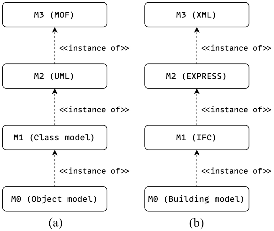
In an attempt to mitigate the aforesaid model incompatibility issues, the Industry Foundation Classes (IFC), 17 which describe an open format for model and data exchange in BIM, were introduced. As such, one of the IFC’s primary objectives is obliterating media disruptions and improving collaboration by liberating BIM models from vendor-specific formats. In its definition, the IFC expresses a stark resemblance to the Unified Modeling Language (UML) 18 by employing analogous model levels (cf. Figure 2, p. 3). As for the UML (cf. Figure 2(a), p. 3), the metametamodel (M3), which allows for the very definition of the UML (M2), is defined by the Meta Object Facility (MOF). 19 Subsequently, the UML is used for formalizing class models (M1) which are finally employed for instantiating object models (M0). On the contrary, for the IFC (cf. Figure 2(b), p. 3), the metametamodel (M3) is defined by the eXtensible Markup Language (XML), 20 which is used for the definition of the EXPRESS schema language, 21 a data modeling language for product data and, in the context of BIM, the metamodel (M2) of the IFC (M1). The IFC in turn finally is used for instantiating concrete buildings or object models (M0).
Model-level analogies between the UML and the IFC. (a) UML modeling levels and (b) IFC modeling levels.
We argue that forasmuch as the previously discussed lack of model federation and tool interoperability, this conceptual parity between the UML and the IFC merits investigating the application of established techniques and tools from model-based engineering 22 for alleviating the aforesaid issues. In light of this conjecture, we propose a model-based tool environment atop which we establish an agile, continuous planning process for regressive, model-based building simulations (cf. section 5). By facilitating workflow modeling 23 coupled with model-based tool integration (MBTI), 24 we propose a solution to mitigate media disruptions at the model level and enable tool continuity by aligning BIM model concepts with BEM model concepts at the process level (cf. section 5). MBTI focuses on the integration of different tools’ metamodels to provide a proper basis for a (semi-)automatic model integration, 24 thereby relying on model transformations 25 that map a source model into a target model. MBTI thus is the basis for our understanding of tool continuity by allowing for the seamless integration of BIM and BEM tools into BIM2BEM workflows. This bears a strong resemblance to the principle of agile software engineering, 26 which substantially relies on the (semi-)automated, continuous, and regressive execution of development tasks, thereby emphasizing iterative development, collaboration, and flexibility to adapt to changing requirements. 27 Agile engineering prioritizes delivering functional software in short, incremental cycles, enabling rapid feedback and continuous improvement. 28 In the context of BIM, our proposed solution qualifies as an openBIM approach by unlocking tool boundaries. 29
As of the earlier established conceptual congruence between the IFC and the UML (cf. Figure 2, p. 3), in the remainder of our paper, whenever we refer to a BIM model, we refer to a BIM model represented using the IFC instead of a vendor-specific format.
1.1. Organization
Section 2 motivates the research problem of our work, followed by section 3 which provides the context of our work. Section 4 then presents the challenges and contributions. Section 5 introduces our proposed solution, followed by section 6, which introduces our modeling methodology. Section 7 discusses the simulation methodology. Section 8 presents the developed tool environment. Section 9 evaluates our proposal and positions it concerning related work. Finally, section 10 concludes our contribution.
2. Research problem
Our work is rooted in BIM2BEM-Flow (B2BF), a nationally funded, interdisciplinary research project among computer scientists, civil engineers, building physicists, and a general contractor. It aims to establish an integrated workflow for BEM. Starting from a BIM model and a property server, i.e., a database describing the structure of the properties of building elements and their materials (cf. section 8), BIM2BEM enables augmenting the BIM model with energy efficiency–related building element properties for conditioning it for energy modeling and simulation. Results from these simulations then are used for evolving and optimizing the building design toward preset energy goals. Current tool incompatibilities between BIM, or design, and BEM, or simulation, tools, demand the (semi-)automatic inference of a BEM model from a BIM model, e.g., using template-based model transformations to map a source (e.g., the BIM) model to a target (e.g., the BEM) model. 25 B2BF requires collaborative work among multiple stakeholders, viz. planners, designers, building physicists, and data and control engineers during the planning and design phases (cf. Figure 3, p. 4) and enables the seamless integration of BIM and BEM tools in an integrated workflow that alleviates model incompatibilities between BIM and BEM.
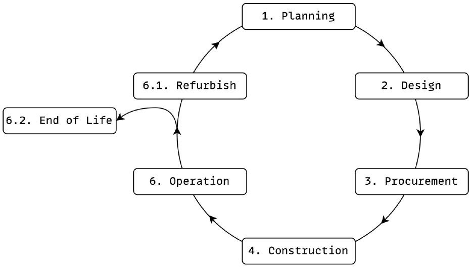
Simplified overview of building life cycle phases after BS EN 16310 30 with the Initiative and Initiation phases collapsed into a single Planning phase.
At the beginning of the project, we have conducted a workshop on BIM-based BEM with general contractors, building physicists, academics, and building operators (11 individual, corporate representatives in total) under the auspices of “Digital findet Stadt” 31 on 10 May 2022. The goal of this workshop was to assess the potential of BIM-based BEM alongside discussing the necessary process, model, and tool requirements. Participants pointed out the relevance of BIM-based BEM during the early stages of a project, where the optimization potential usually is the greatest, especially in the area of geometric parameters and building configuration. In addition, the application of BIM-based BEM provides a good opportunity to examine different planning variants and their ramifications on a building’s energy consumption. Regarding expectations and requirements toward BIM-based BEM, participants pointed out the need for clear and lossless data flows among project participants. In line with this, bidirectional data exchange between both BIM and BIM and BEM tools was further mentioned as a key requirement for BIM-based BEM to succeed. Apart from these expectations and requirements, participants further mentioned a lack of definitions and standardizations of modeling requirements and necessary model metadata, and a prevalent lack of interfaces between individual software products (BIM and BEM tools). This blatantly reflected in that a building’s geometry usually arrives in the BEM tool, yet model metadata (e.g., weight or material properties) do not. Put differently, for BIM-based BEM to thrive, model standardization is inevitable. Per this, participants finally pointed out the need for the presence of building physics values (e.g., heat transfer coefficients) in structural and hierarchical, object-based models (cf. the UML).
In synopsis, the overarching message of this workshop was that BEM has enormous potential, e.g., energy efficiency optimization or environmental impact reduction, 32 among others, but currently lacks a conceptual and technologically integrated, model-based workflow. Throughout the rest of our paper, we refer to the results from this workshop to confirm issues, strengthen claims, and justify our contributions.
B2BF at a larger scale addresses issues that are further detailed in the “Technical Report for BIM-BEM Workflows” 33 from buildingSMART International (buildingSMART International is the worldwide organization driving digital transformation of the construction industry through the creation and adoption of open, international standards like the IFC). This report investigates currently established BIM2BEM processes together with their data and technological requirements that appear and change throughout the phases of a building’s lifecycle (cf. Figure 3), thereby identifying prevalent issues in current processes, viz.: 33
Inconsistent project delivery processes, i.e., there is no single standard means in which project information (e.g., BIM and BEM models) are developed and turned over to project stakeholders.
Discrepancies between reality and idealized models, i.e., there are fundamental discrepancies between the predictions of BEM tools and the reality of how a building eventually performs.
Varied requirements by jurisdiction, i.e., energy analysis varies greatly from jurisdiction to jurisdiction, including its optional use, prescribed methodologies and tools, regional climatic variations, and fiscal incentives/penalties for compliance.
Varied requirements by standard/protocol, i.e., energy standards and certification protocols used throughout the world. These vary in specific targets or ranges acceptable for compliance.
Varied responsibility or liability, i.e., depending on the individual project, responsibility for energy analysis may differ, e.g., by being led by an architect, an engineer, or a specialized design consultant, each with a different focus and approach.
Variable return on investment (ROI), i.e., the ROI of the resulting design and construction implementations may vary between locations/jurisdictions, projects, and owners.
Variety of methodologies and technologies, i.e., many simulation tools can be found throughout the industry, but they have different underlying technologies and use different methodologies resulting in different focuses of scale, detail, and process.
Ineffective BIM2BEM interoperability, i.e., general interoperability, even among BIM tools/platforms, has plagued the industry for decades, regardless of the best efforts by standardization bodies (e.g., buildingSMART).
Our work tackles issues 1, 7, and 8 as reported by buildingSMART International’s “Technical Report for BIM-BEM Workflows.” 33
3. DTs, BIM, and BEM
DTs, BIM, and BEM are related concepts from the AECO domain to improve the design, construction, and operation of buildings, in particular a building’s energy performance. This relationship is illustrated in Figure 4. Designers create the design of a building by considering relevant trades, e.g., design, materials, sun shading, or artificial lighting, whereas Building physicists are concerned with engineering and optimizing the energy efficiency of buildings by conditioning the BIM model for BEM by incorporating trades like energy flow, occupant behavior, or building automation. In addition, Building physicists also may update sun shading or artificial lighting trades to meet energy performance goals. In this scenario, the DT serves three objectives:
During early planning phases, the DT serves as the collaborative planning and simulation environment to optimize the building’s design toward energy efficiency, comfort, and sustainability.
During the operation phase, the DT serves as the simulation and optimization environment to optimize daily building operations toward energy efficiency, comfort, and sustainability.
During renovation, the DT serves as the assessment, simulation, and optimization platform to identify retrofitting potentials to improve buildings’ energy efficiency. (Obviously, this requires the recreation of BIM models if they do not yet exist, which often is the case for old buildings. We do not cover model recreation in this work.)
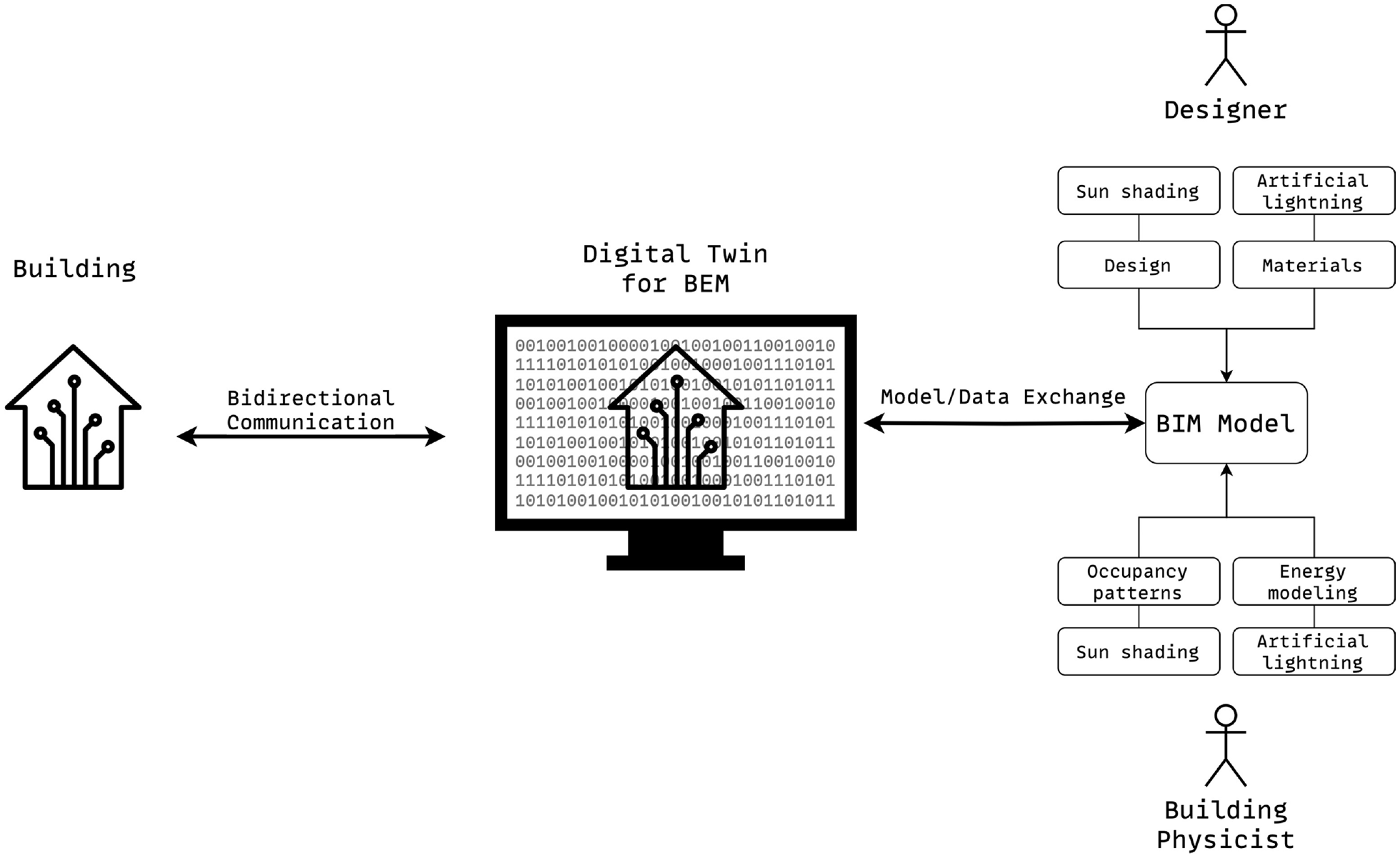
BIM2BEM context.
Crucially, during the operation phase, the DT is connected to the physical building via means for bidirectional communication, which eventually allows for real-time monitoring, analysis, and optimization of daily building operations. In the following, the triad DT, BIM, and BEM is discussed in more detail.
3.1. Digital twins
DTs—virtual, model-based replicas of CPSs, processes, and other physical objects—have garnered considerable interest in recent years. 34 Various industries, including manufacturing, construction, or transportation, utilize DTs to construct virtual replicas of physical assets to facilitate planning, simulation, real-time monitoring, and predictive maintenance of the twinned asset. 35 Consequently, DTs provide increased planning and operational efficiency, decreased outages, improved product quality, optimized resource utilization, and enhanced innovation through simulation with, and analysis of real-time data. 35 In particular, the AECO domain seeks to adopt DTs to improve project design, planning, simulation, construction management, and facility operations, with the hopes of enhancing collaboration, saving costs, and optimizing asset performance over the entire building life cycle (cf. Figure 3, p. 4), e.g., by applying BEM 8 for optimizing a building’s energy footprint. Specifically, a DT for BEM that incorporates building data, BAS information, and environmental conditions permits building owners, operators, designers, and building physicists to simulate, analyze, predict, and optimize energy consumption, occupant comfort, and overall building performance. These scenarios demand the presence of high-quality and interoperable models for the establishment of an exchangeable, high-fidelity, and accurate virtual representation of the twinned asset, which also provides the required level of detail to enable accurate simulations. 1 At present, the AECO domain often lacks the necessary model interoperability to realize such scenarios12–14,33 which was also confirmed during our workshop (cf. section 2) by citing lacking definitions, standards, and interfaces for models as a key objector to an integrated BIM2BEM workflow.
3.2. Building information modeling
Despite having been conceived in the 1990s, 36 BIM has only recently gained prominence and broad industrial acceptance. In theory, BIM describes a process that resembles virtually integrated design, construction, and operation (ViDCO) by comprising object-based modeling, model-based collaboration, and network-based integration. 37 This conception of BIM is strikingly similar to the concept of a DT. 4 In particular, a DT for BEM uses (1) BIM models that besides the building’s design also specify sensors (e.g., temperature, humidity, or occupancy) and BAS information, (2) environmental conditions, and (3) real-time building data to enable building owners, operators, designers, and building physicists to simulate, analyze, predict, and optimize energy consumption, occupant comfort, and overall building performance. 38 The realization of these scenarios necessitates that the AECO domain transitions from its established Design-Bid-Build process to a more agile and continuous Design-Build-Operate process that capitalizes on the close collaboration of all stakeholders throughout the entire building life cycle. 39 Such a working style is highly reminiscent of the idea of agile engineering (cf. Figure 5) in software engineering, 26 which was introduced in the early 2000s based on the idea of a fast reaction to changes, a focus on overarching goals, and continuous quality assurance. Analogously, the establishment of agile process cycles in the AECO domain delivers the basis for modern, iterative cross-phase processes as exemplified in Figure 6. The resulting agile process cycles then encompass building blocks such as BIM to BEM, building state prediction and monitoring, automated commissioning, as well as tracing sustainability goals across phases. Crucially, the establishment of such continuous improvement processes across phases can substantially improve overall building performance. 40
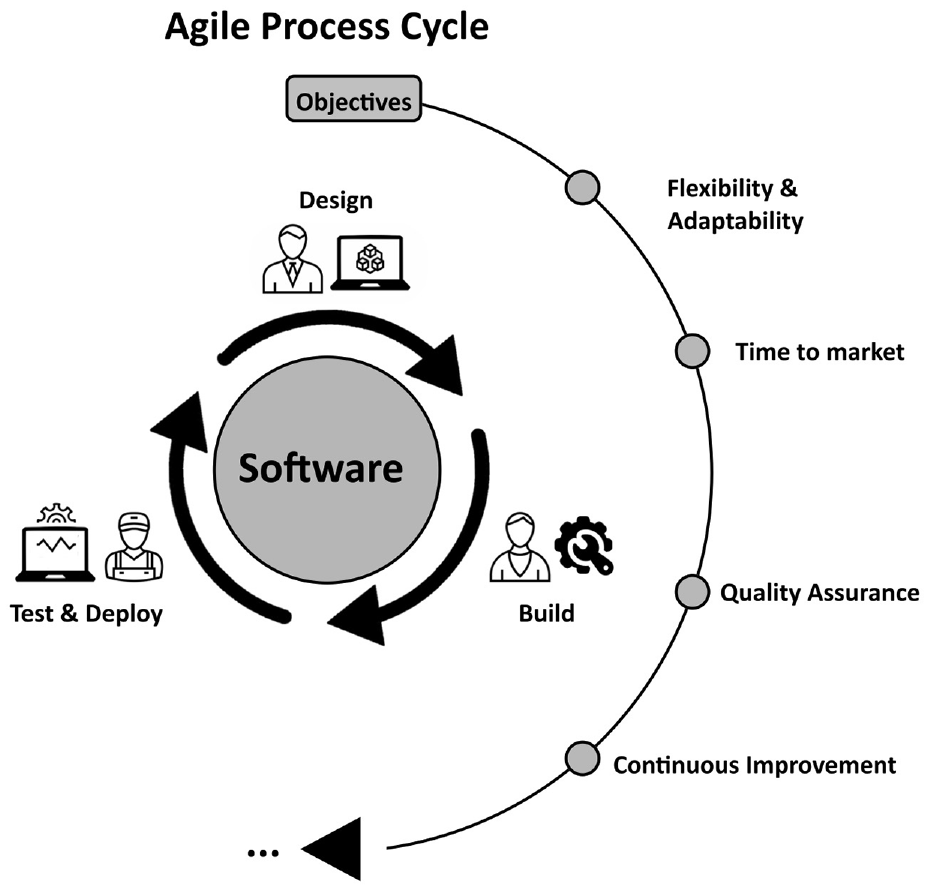
Agile engineering as applied in software engineering which comprises designing the software, building it, testing, and subsequently deploying it in each process cycle. At this, agile engineering is liable to various objectives that merit success in software engineering projects.
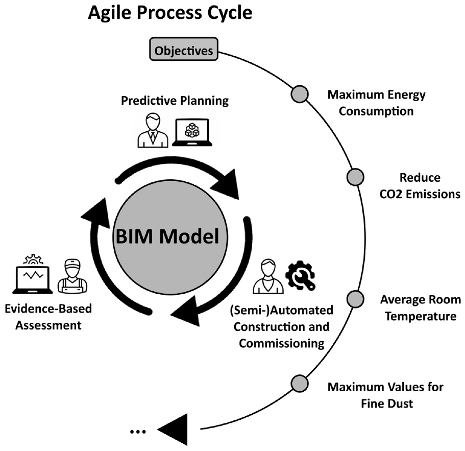
Exemplification of the idea of agile process cycles in the AECO domain for the continuous assessment of target objectives which in turn results in an iterative evolution of a building’s design.
The earlier discussed absence of tool interoperability; however, substantially obstructs this transition. During our workshop (cf. section 2), this lack of tool interoperability was identified as the most serious issue in BIM and BEM and is caused by the absence of model metadata support, e.g., any data except geometry data are typically not shareable and exchangeable between different tools.
3.3. Building energy modeling
Unlike BIM, which focuses on the process of creating and managing a digital representation of a building or infrastructure project, BEM focuses on the simulation of a building’s energy performance. 41 BEM assesses the energy consumption and efficacy, and thermal comfort of a building and its’ systems, such as HVAC, lighting, insulation, and other BASs using specialized software. 41 BIM and BEM are related through the integration and exchange of information. BIM can provide valuable input data for BEM, such as building geometry, material specifications, and energy requirements. 42 Ideally, the information captured in the BIM model can be utilized to construct an accurate and efficient BEM model for building performance simulation. Due to the aforesaid model federation and tool interoperability issues in BIM (cf. section 3.2), which naturally propagate to BEM, 15 there currently yawns a substantial conceptual and technological gap in realizing such an integrated BIM2BEM workflow.13,14,33 This is epitomized most notably by inaccurate BEM simulations, 15 as also confirmed in our workshop (cf. section 2). Insufficient support for model and data exchange between BIM and BEM tools, i.e., BEM tools misinterpret BIM models and data, yield inaccurate simulations, which is a major challenge in implementing BIM2BEM. 15 On a broader scale, this indicates that the AECO sector lacks a conceptual foundation for continuous simulation, tracing, and analysis of a building’s energy performance throughout its life cycle, which significantly impedes the development of energy-efficient buildings.
In a nutshell, the triad DT, BIM, and BEM unify related concepts that utilize models, data, and technology to enhance the design, construction, and operation of buildings. BIM facilitates collaborative design and information management. DTs provide a platform for the virtual representation of a building given BIM models. BEM then concentrates on simulating and optimizing the energy performance of buildings inside the DT by utilizing data from BIM models and the building itself (cf. Figure 4).
4. Challenges and contributions
Commensurate with section 3, we identify four major obstacles currently impeding regressive, model-based building performance simulations using an agile, continuous planning and design process, viz.:
Lack of a conceptual and technological approach for an integrated BIM2BEM process yielding little to no interaction and collaboration among stakeholders.
No conceptual and technological foundation for continuous and regressive BEM.
Lack of means for specifying and resolving dependencies among different trades in BIM models as well as BIM and BEM tools, i.e., property management using a property server.
No conceptual and technological foundation for tracing anticipated/actual energy consumption throughout the building life cycle.
In light of these obstacles, we propose a model-based tool environment for regressive BEM that capitalizes on MBTI for enabling seamless model interchange and continuity among BIM and BEM tools. Our environment supports the model-based definition of continuous BIM2BEM workflows which specify both BEM model and tool requirements, and model-based tool mappings between BIM and BEM tools for regressive, model-based building performance simulations, thereby linking the technological and process levels. 14 In synopsis, we deliver:
a model-based tool environment for improving collaboration, model federation and fidelity, and interoperability in BIM2BEM,
and, atop this tool environment:
an agile, continuous model-based planning process for regressive model-based building performance simulations,
thereby targeting the following research questions:
RQ1. How to improve collaboration between experts in various trades for BIM and BEM?
RQ2. How to implement an agile, continuous planning process for regressive building performance simulations?
RQ3. How to establish a foundation for tracing anticipated and actual energy consumption of a building throughout its entire life cycle?
Our contribution is structured as Design Science Research (DSR) 43 and provides artifacts to facilitate building simulations for DTs. The development of our artifacts begins with requirements elicitation and concludes with prototyping, experimentation, and an expert survey. Our artifacts are deployed as a solution to the following design science problem, outlined using the DSR template: 43
In the field of DSR, the term artifact typically refers to a prototype that represents a conceptual solution at a relatively early stage of technological development, specifically at Technology Readiness Level 3 (TRL3). Our proposal utilizes model-based engineering and a cyber demonstrator (cf. sections 5–8), which achieves TRL5. Our proposed tool environment (cf. section 8) is prepared to be scaled up for a higher TRL solution (cf. section 9) in future.
5. Agile, continuous building energy modeling and simulation
Our proposed solution as presented later in this section has its cause in BIM-based BEM 41 as discussed in section 2. BIM-based BEM historically has suffered from lacking model and tool interoperability.12–15,33 In the following, we narrow down on the actors and use cases in BIM-based BEM (denoted UCX in the following; cf. section 5.1), and their associated requirements (denoted RX in the following; cf. section 5.2) as prompted to our proposed solution (cf. section 5.3).
5.1. Actors and use cases
Traditionally, any BIM2BEM process starts with design modeling [UC1] to establish the initial BIM model of the building, which usually is done by a designer. In a next step, a building physicist creates a BEM model [UC2] from/atop this BIM model for later simulation inside a BEM tool. Notably, this requires facilities for exchanging models [UC3] among designers and building physicists, and means for automated translation of BIM models into BEM models [UC4] to enable building performance simulation [UC5]. Recall that current BIM and BEM tool, and consequently model incompatibilities, render this translation step essential. To assure flawless execution of these activities, a BIM coordinator supervises these activities and ensures compliance with the Exchange Information Requirement (EIR; an EIR defines all the requirements related to the information exchanges of a specific BIM process.) by assuring deliverance of these requirements by both BIM and BEM tools and models. In particular, the BIM coordinator specifies a BIM2BEM workflow model [UC6] which formalizes the EIR’s requirements, and associated tool mappings [UC4] for automated translation of BIM models into BEM models. The modeling (or deliverance) of these requirements by both designers [UC1] and building physicists [UC2] inside BIM and BEM models demands a dedicated property server [UC7] for provisioning the necessary model extensions by building element properties. Currently, modeling and especially subsequent exchange of such requirements falls into the category of “unsupported model metadata” (cf. section 3.2). Finally, with an accurate BEM model given, building physicists eventually perform building performance simulations [UC5] with a corresponding BEM tool that satisfies the necessary tool requirements at a technical level, and subsequently, assess the results against predefined energy performance goals [UC8]. In the event of changes to the BIM model, the BEM model is automatically re-established using the tool mappings to conduct the BEM simulations once more.
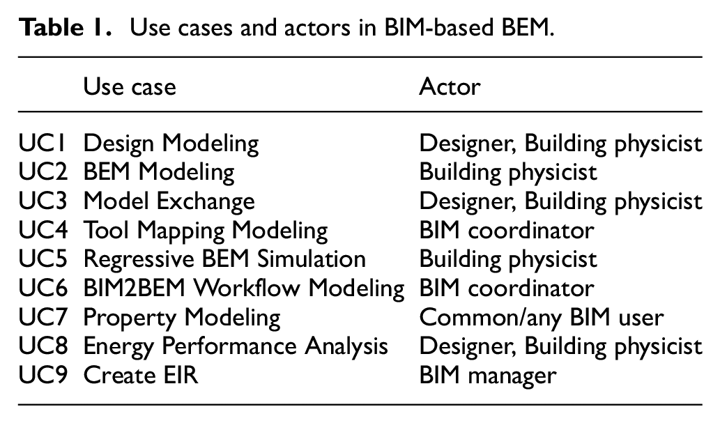
Table 1 summarizes our discussion of use cases and actors. The last row, Create EIR [UC9], is added for completeness but grayed out as we do not address the creation of an EIR in this work but instead assume it is given. The common/any BIM user as mentioned in Table 1 (and below in Figure 7) for Property modeling refers to any BIM expert, e.g., the BIM manager, BIM coordinator, or Designer.
Use cases and actors in BIM-based BEM.
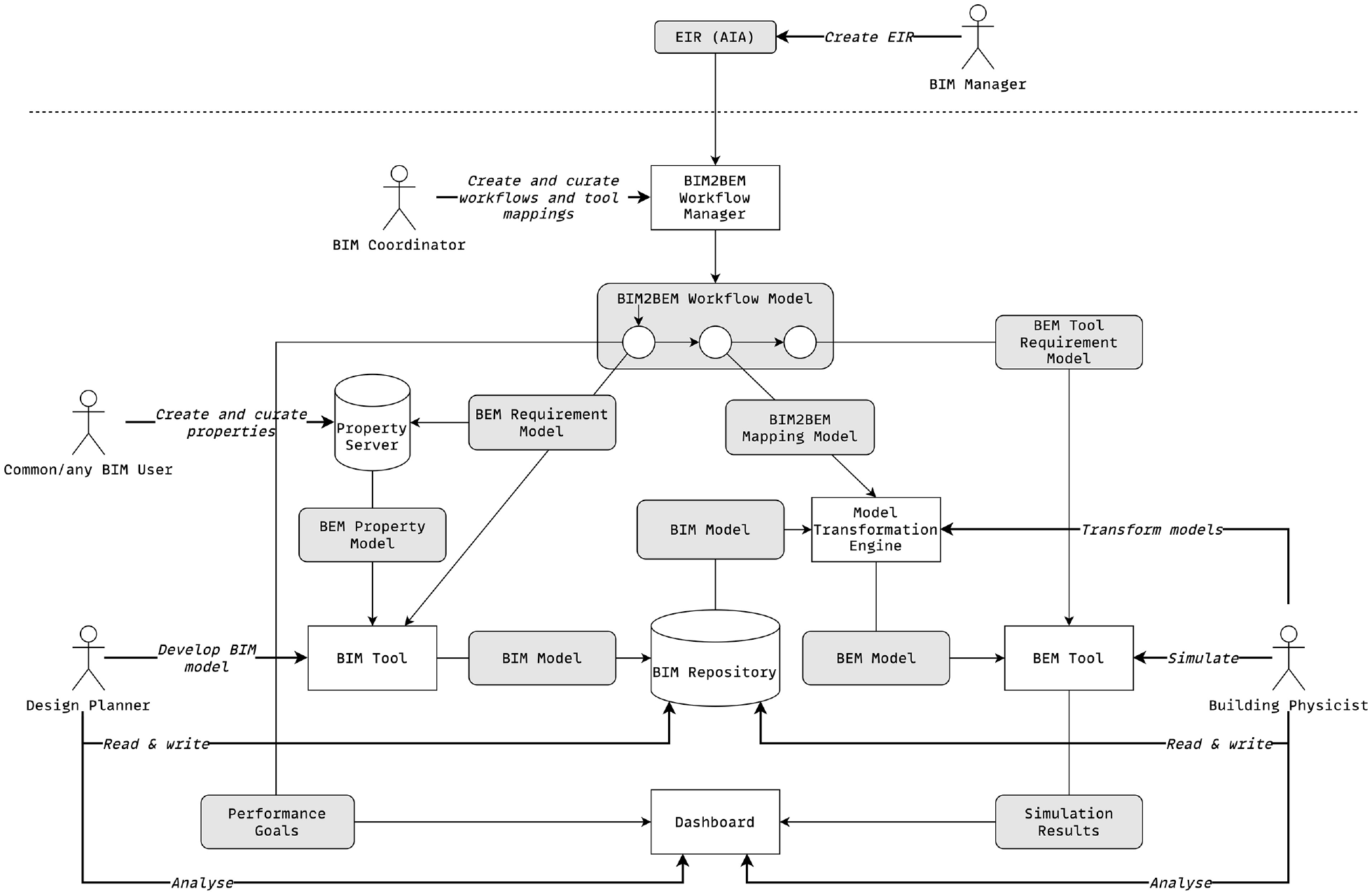
Conceptual model of our proposed solution.
5.2. Requirements
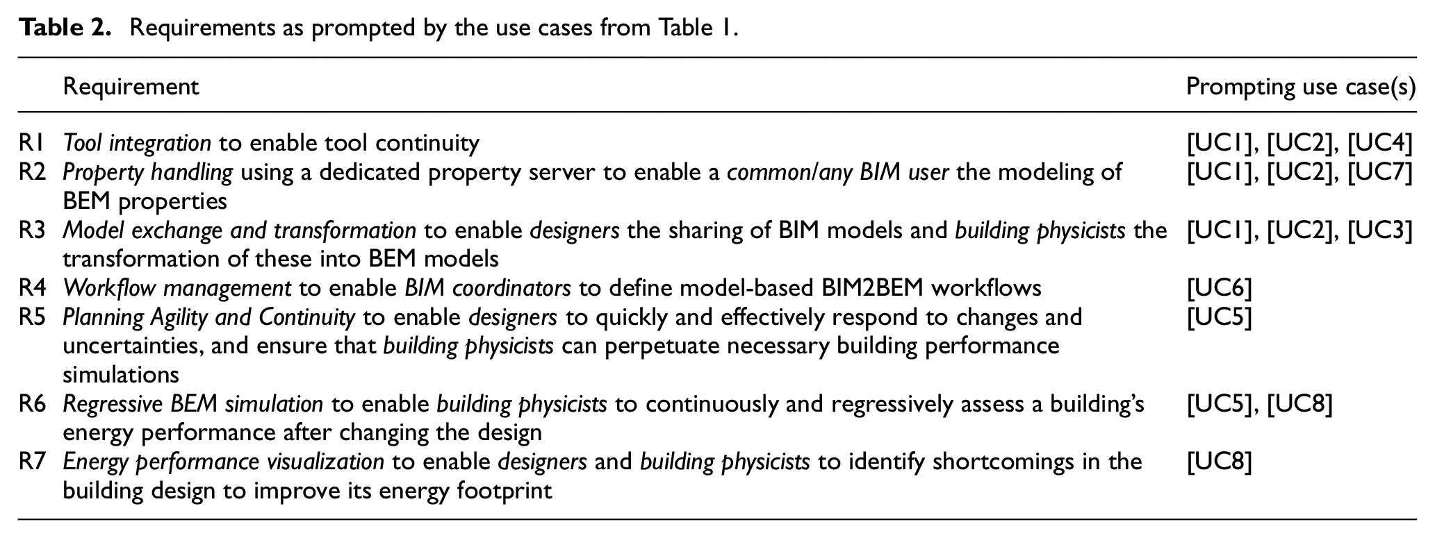
Design and BEM modeling, i.e., [UC1] and [UC2],—when considered in isolation—would not require any further treatment, as the market currently offers a plethora of tools for realizing these use cases. However, dealing with these tasks separately usually results in inaccurate BEM models and simulations. 15 In our proposal, we thus treat design and BEM modeling as a coupled activity, jointly enabled by [UC3], [UC4], and [UC7]. Collectively, these use cases prompt a triad of requirements, viz. tool integration to enable usage of BEM tools (cf. tool continuity) [R1], property handling to condition BIM models form BEM [R2], and model exchange and transformation [R3]. If delivering these requirements, designers can (1) create a BIM model [R1] in alignment with the established modeling requirements (cf. the EIR) which are integrated from a property server [R2] (cf. section 8) and (2) share it with building physicists [R3] who in turn transform the BIM model into a corresponding BEM model for use in a BEM tool [R1]. To establish the BIM2BEM workflow model [UC6], dedicated workflow management for the establishment and curation of these workflows is necessary [R4].
The deliverance of [R1]–[R4] establishes the model-based tool environment (cf. section 8) for zooming in on the remaining use cases, viz. [UC5] (regressive BEM simulation) and [UC8] (energy performance analysis). The foundational requirement for these two use cases is planning agility and continuity [R5] which allows designers and building physicists timely reaction to and hence incorporation of changes in the building’s design [UC5]. This demands the capability to re-execute BIM-based BEM simulations regressively [R6], i.e., after a change, and subsequent evaluation and comparison of simulation results [R7] to assess building performance [UC8].
Table 2 summarizes our requirements’ elicitation by correlating each established requirement with their prompting use case(s).
Requirements as prompted by the use cases from Table 1.
5.3. Solution overview
From the requirements in Table 2, we propose the solution as outlined in Figure 7. We use MBTI as the bridging mechanism to enable tool continuity by transforming BIM models into adequate BEM models for simulation. MBTI mitigates media disruptions by integrating common design and planning tools at the model level. This defines the scaffolding for an agile, continuous planning process to facilitate regressive, model-based building performance simulations using workflow modeling.
Starting from an EIR document which is created by the BIM manager, the BIM coordinator defines the BIM2BEM workflow model [R4] with the BIM2BEM workflow manager. The BIM2BEM workflow model comprises energy Performance goals for the building, the BEM requirements model for the BIM model, the BIM2BEM mapping model for transforming the BIM model into a BEM model, and the BEM tool requirements model specifying BEM tool requirements. The BEM requirements model specifies which BEM properties need to be available from the Property server [R2] for that the designer can deliver these in the BIM model from the BIM tool. The BIM repository is the collaborative hub where designers share BIM models [R3]. Building physicists can check out these BIM models and transform them into BEM models [R3] using the model transformation engine whose operation relies on the BIM2BEM mapping model [R1]. Finally, building simulations are conducted with the BEM tool [R6] whose results are visualized on a dashboard for correlation with the preset Performance goals [R7]. The model-based nature of our proposal naturally equips it with the necessary agility by capturing changes at the model level from where they are further propagated [R5]. The high degree of automation unlocked by model-based engineering further equips our proposal with the necessary tool continuity [R5] using model transformations to bridge otherwise incompatible tools [R1].
5.3.1. Interpretation of agility and continuity
Our proposal considers agile, continuous planning and regressive BEM simulations after changing a building’s design by realizing the necessary tool continuity. Figure 8 visualizes the different manifestations of agility our solution proposal facilitates and how we eventually achieve tool continuity.
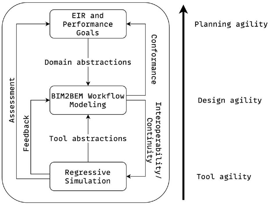
Manifestations of agility facilitated by our solution proposal.
In particular, at the tool level, our proposal provides the necessary tool continuity and interoperability by utilizing MBTI as part of BIM2BEM workflow modeling for capturing tool abstractions as BIM2BEM model transformations. On the planning level, this, in turn, provides the necessary freedom to specify domain requirements, e.g., energy performance goals and modeling requirements as part of an EIR, independent of the underlying technological layer. Finally, the design level incorporates planning-related domain abstractions according to an EIR and performance goals, as well as technology-related tool abstractions for tool continuity and interoperability within a unified workflow paradigm. A natural benefit of our model-based approach is its transparent integration of change management. By design, model-based approaches facilitate efficient detection of design changes,6,44 e.g., for regressive building performance simulations. Results of these simulations eventually allow for assessing the achievement of performance goals as well as updating the design according to the feedback provided within these results. Crucially, our proposal supports change along all layers (cf. Figure 8), i.e., (1) the integration of further tools for additional simulations, (2) change and adaptation of performance goals, and (3) consequently the establishment of novel workflows. Our proposal thus by design enables an agile working style and aligns with recent advances in the AECO domain that propagate a transition toward agile engineering, specifically in the early design phases of construction projects. 40 At current, however, the AECO domain struggles in implementing agile practices due to a lack of tool environments that would support effective data serialization between design and analytics processes without affecting the collaboration between team members. 45 Our proposal delivers a tool infrastructure that tackles these issues.
6. Modeling methodology
This section introduces the modeling methodology underlying our proposal and meant to be applied early during the design and planning phase of a building. The corresponding simulation methodology is introduced in section 7.
Scope: The modeling methodology covers the specification of BIM2BEM workflow models which by design integrate BEM requirements and BEM properties, including the definition of model-based tool mappings. The specification of an EIR which usually takes place before planning and design is out of scope.
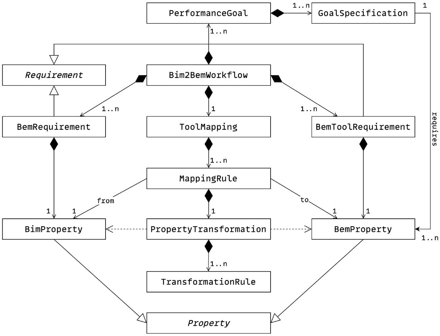
Modeling languages: Ecore 46 is used for modeling BIM2BEM workflows, comprising the Performance goals, the BEM requirements and BEM tool requirements models, the BEM properties (cf. Figure 10), and the model-based tool mappings (cf. Figure 9). Ecore is conceptually identical to UML, i.e., it employs the same modeling levels (cf. Figure 2) with support for implementing the MOF, yet, it is specifically designed for metamodel specification. In addition, Ecore is implementation independent, i.e., it does not require dedicated modeling environments that implement the full UML specification, 18 thus providing us with a lightweight and flexible modeling infrastructure.
BEM workflow model.
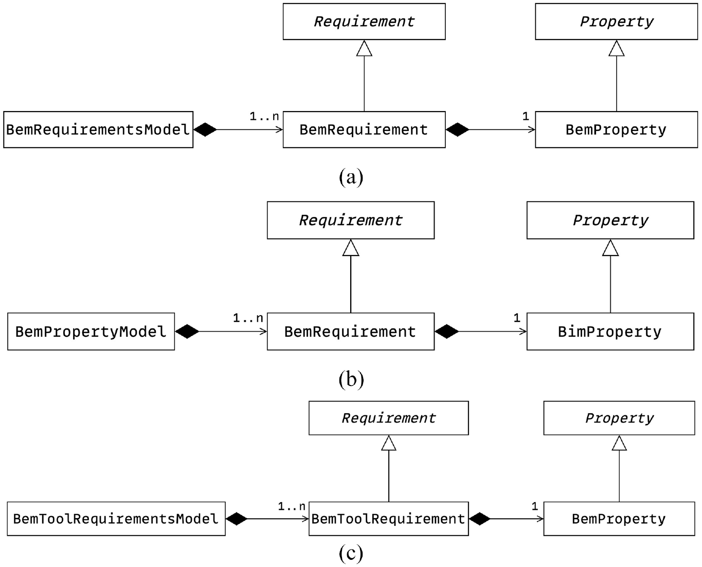
BEM requirements, property and tool requirements models. (a) BEM requirements model. (b) BEM property model. (c) BEM tool requirements model.
6.1. BIM2BEM workflow model
The BIM2BEM workflow model shown in Figure 9 orchestrates our tool environment (cf. Figure 7) by specifying the steps comprising building performance simulations. It defines the BEM requirements that need to be delivered by the BIM model, i.e., the BIM model has to contain necessary BEM properties (e.g., material characteristics) which the BEM tool needs to run simulations. On the BEM tool side, these requirements are captured by the BEM tool requirements model to define the features a BEM tool has to implement.
The BEM tool requirements model for the BEM tool and the BEM requirements model for the BIM tool (and the property server, respectively) need to provide the necessary level of detail and capture requirements analogously. If not, the resulting BEM property model from the property server does not fulfill these very requirements, e.g., material information may be missing or differing units are used in the BIM and BEM tools. By automatically extracting and inferring these requirements models from the BIM2BEM workflow model, we assure that requirements are consistent among BIM and BEM tools. Figure 10 depicts the structure of both aforesaid requirements models (cf. Figure 10(a) and (c)) as well as the associated BEM property model (cf. Figure 10(b)) which specifies the modeling conventions for the BIM model.
Aside from establishing the aforesaid modeling conventions, the BIM2BEM workflow model further defines the model-based tool mappings to transform a BIM model into a BEM model (cf. section 5). In particular, the BIM2BEM workflow model allows for the definition of Tool mappings that comprise Mapping rules
25
for converting a BIM property to a BEM property using Property transformations. These Property transformations comprise pattern-based Transformation rules that specify a source pattern using Universally unique identifiers (UUID; by convention, each element of a BIM model has associated a unique identifier for unambiguous identification throughout the AECO sector.) to then apply the transformation operation (op) converting the BIM property into a BEM property.Figure 11 shows an excerpt of a BEM workflow model with a tool mapping for the BEM Tool DALEC
47
that converts the BIM property“Maximum Illuminance” into the BEM property“Daylight Illuminance” by transforming the
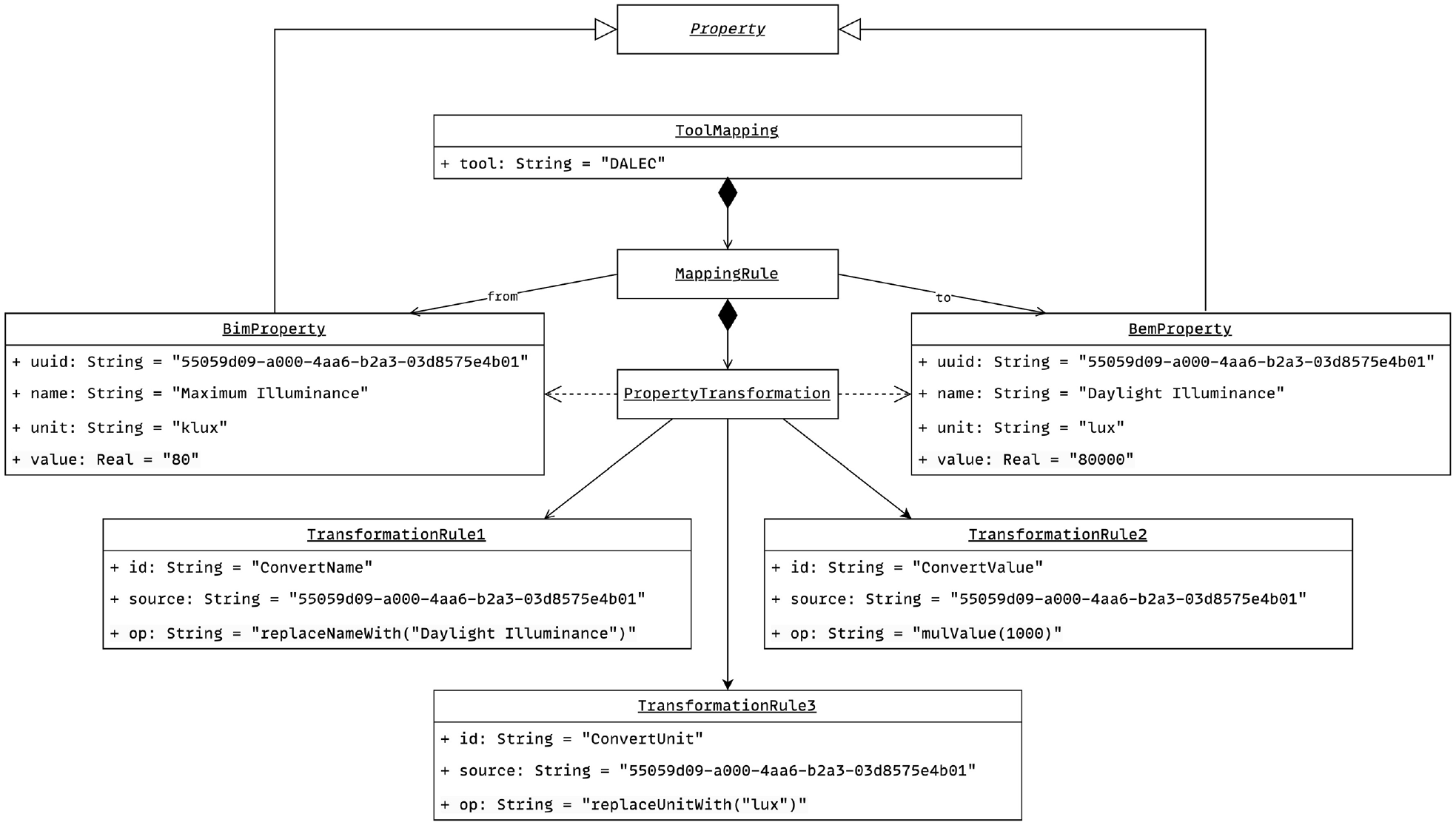
Sample tool mapping as specified in the workflow model.
Modeling of a building energy PerformanceGoal.
6.2. BIM2BEM modeling steps
The modeling procedure for establishing the BIM2BEM workflow model consists of four steps: (1) specifying the BEM requirements model, (2) specifying BEM properties, (3) specifying the model-based tool mapping(s), and (4) specifying Performance goals. They may be accomplished in any order, so long as the logical dependencies between them are respected:
Specifying the BEM requirements model. This step starts with the formalization of necessary BEM requirements from the EIR which are required for accurate and sound building performance simulation. Specifically, to conduct building performance simulations, the BIM model must contain distinct properties for the BEM tool to work correctly. These properties describe the set of BEM requirements which result in the BEM requirements model. Conceptually, this model breaks down to an aggregation of BEM properties (cf. Figure 10(a)) as depicted in the right side of Figure 11. The BEM requirements model is used to automatically infer the BEM property model and the BEM tool requirements model for the BIM and BEM tools, respectively.
Specifying BEM properties. Given the BEM requirements model, the necessary BEM properties are modeled inside a Property server (cf. section 8). From there, the BEM property model (cf. Figure 10(b)) is automatically inferred and forwarded to the BIM tool for integrating the specified BEM properties into the BIM model by augmenting it with adequate BIM properties from the Property server. This ensures that the BIM model implements the BEM requirements model. The left side of Figure 11 shows an example of a BIM property with its corresponding BEM property on the right. Both are associated via a Property Transformation to map the property between BIM and BEM tools (see below under (3)).
Specifying the tool mapping. To run building energy simulations using a BEM model, model-based tool mappings that transform the BIM model into a valid BEM model are required. This demands the definition of Transformation rules that map BIM properties from the BIM model onto their corresponding BEM properties in the resulting BEM model. Consequently, the resulting BEM model conforms to the BEM tool requirements model which specifies the technical features the BEM tool has to implement for running the necessary building performance simulation, e.g., BIM-based BEM simulations, w.r.t. the aforesaid Performance goals (cf. Step (1)). Figure 11 shows an example of a model-based tool mapping for the BEM tool DALEC 47 as used in our work (cf. sections 7 and 8) with three distinct Transformation rules that map one BIM property to a BEM property.
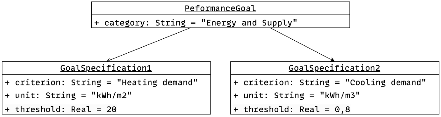
Specifying Performance goals. Completing the BIM2BEM workflow model requires the specification of Performance goals. Analogously to the BEM requirements (cf. Step (1)), these originate from a building standard and are aligned with the BEM requirements (cf. Figure 9), i.e., the BEM requirements assure that the BIM model and the thereof generated BEM model deliver the necessary BEM requirements to run building performance simulations that allow assessing the specified Performance goals. Figure 12 shows an example of a modeled Performance goal with two distinct assessment criteria, i.e., GoalSpecification1 and GoalSpecification2.
As for handling change requests, model-driven engineering is broadly acknowledged to provide sophisticated change management. 48 That said, our proposal is capable of reacting accordingly to changing requirements (cf. Performance goals). Usually, the source of such changes lies in some regulation body. This consequently requires careful work by both the BIM manager and coordinator to integrate all changes originating from such aforesaid regulation bodies into the EIR, and consequently, the BIM2BEM workflow model. However, once integrated, these changes automatically propagate to any model downward in the engineering chain. 48 Our tool environment and its modeling methodology thus naturally allow for change management given the careful specification of any changes by the BIM manager and coordinator. Observe that our model does not provide dedicated modeling elements to address specifics of any regulation bodies but instead provides abstract concepts for formalizing these (cf. Performance goals and BEM requirements).
7. Simulation methodology
To showcase the feasibility of our proposal and verify its proof-of-concept, in our work, we employ DALEC as the BEM tool used for energy simulations. 47 DALEC is an innovative lighting and thermal simulation application that enables architects to evaluate their individual designs in terms of thermal and visual performance, as well as their impact on the building’s overall energy consumption. 47 In the following, we briefly outline DALEC’s model requirements and modus operandi.
7.1. Simulation model
DALEC consumes input models formalized in IFC. Our proposed framework (cf. section 5) readily allows for conditioning BIM models for BEM for subsequent usage by DALEC. Specifically, DALEC requires the input model to provide the necessary level of detail by specifying relevant simulation parameters, i.e., building element-specific material properties. 47 Our proposed solution assures the presence of these in the BIM model by (1) the BEM requirements model and (2) the Property server which allows for seamlessly integrating these requirements in the BIM model.
In addition to these model parameters, DALEC further requires weather-specific input data, e.g., location, local. and global solar radiation or cloud coverage to run its simulations. Our work does not consider the provisioning of these inputs and assumes them to be already available.
7.2. Simulation approach
DALEC runs simulations within a matter of seconds, i.e., a whole yearly simulation routine with all complex interactions (e.g., heating or artificial and natural lightning) is performed within a second. 47 It does so by employing an innovative approach to precomputing lighting simulation for the most common room setups.
Given the aforesaid input data, e.g., the IFC-based BEM model and necessary weather data, DALEC, in a next step, reduces the room geometry to shoebox geometries. 47 With this simplified BEM model, DALEC performs the computation using dedicated submodules as outlined in Figure 13.
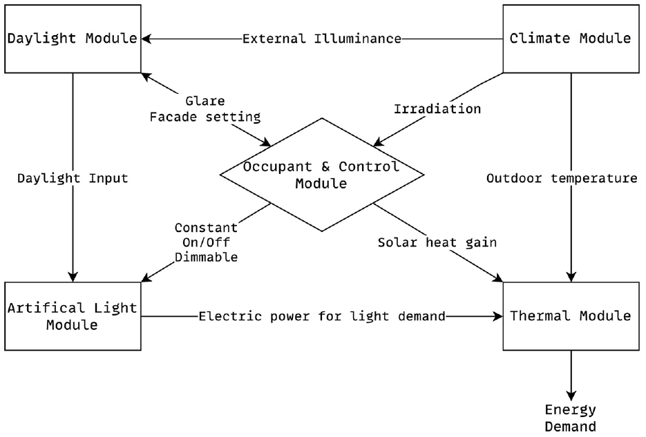
Schematic overview of DALEC’s computational workflow.
The Climate Module is capable of storing and retrieving around 3000 weather data sets from various locations across the world. These data sets are then processed as needed to support the functionality of the other modules. The Daylight Module is responsible for computing the yearly daylight levels in all rooms inside the BEM model. The Daylight Module precalculates both direct sunlight and diffuse skylight. The Artificial Light Module is responsible for determining the hourly electric power requirement of a chosen artificial lighting system. This calculation considers both the hourly amount of natural daylight entering the space and the control strategy used for the luminaires. The Occupant & Control Module is responsible for integrating a range of control techniques related to natural and artificial lighting, heating and cooling, and occupant behavior. Finally, the Thermal Module utilizes the outputs of the aforesaid modules to compute the hourly energy demand for the building being analyzed. The obtained data are then correlated with predetermined Performance goals (cf. section 8) to optimize the design according to these predefined goals.
At this point, we skip any further discussion of DALEC as of not being the main focus of our work and instead refer the interested reader to the reference publication. 47
8. Implementation
Following our discussion of both modeling and simulation methodologies, this section discusses the implementation aspects of our model-based tool environment for building performance simulation (cf. Figure 7).
8.1. BIM repository
The BIM repository implements a collaborative data hub for BIM models with versioning support for collaborative work among multiple stakeholders over a building’s complete life cycle and is currently under active development. Internally, it employs a knowledge graph 49 for persisting the evolving versions of a BIM model. In its latest iteration, it supports exchanging BIM models via a git-like pull/push-mechanism, and change-tracking, allowing moving back and forth in a building design’s evolution. Currently, we are implementing branching and merging of BIM models for the concurrent development of different, potential manifestations of a building, and subsequent re-integration into a single, final BIM model. 50
8.2. Workflow manager
The Workflow manager represents a web application for creating BIM2BEM workflow models. This comprises the aforesaid BEM requirements and BEM tool requirements models, the Performance goals, and the model-based tool mappings. The Workflow manager implements an integrated platform for conducting these modeling steps in a guided way to ensure complete models, i.e., with all steps described under section 6 considered. Crucially, the Workflow manager establishes the “contract” (cf. BEM property model) concerning which BEM requirements to deliver with the Property server. As described earlier, this ensures that BIM models can be converted into adequate BEM models for accurate building performance simulations w.r.t. the specified Performance goals. During the whole process, the Workflow manager in addition checks the conformance of the BIM2BEM workflow model with the requirements from the EIR. Figure 14 shows an excerpt of a workflow as configured with the Workflow manager.
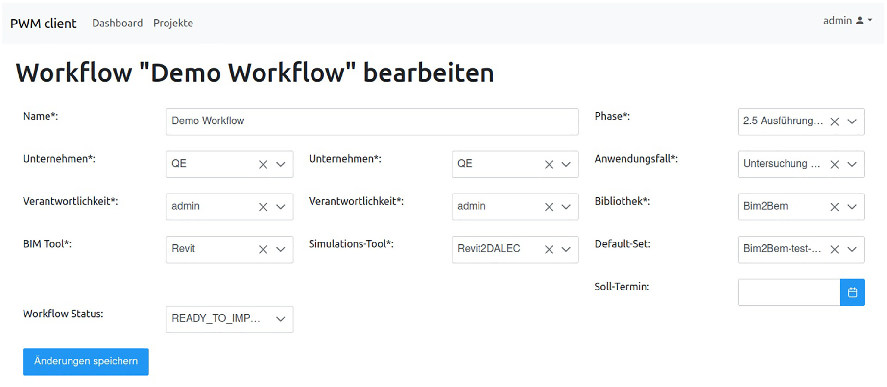
Sample workflow configuration from the Workflow manager.
8.3. Property server
The Property server is a database describing the structure and properties of building elements and their materials. It is accessible via a web interface that allows for the modeling and provisioning of model requirements in the form of BIM properties, which are later transformed into analogous BEM properties. Internally, the Property server implements a building-part library where each building part has associated additional model metadata in the form of aforesaid BIM properties. Specifically, BIM properties refer to the various attributes, characteristics, and information associated with elements within a BIM model, e.g., geometry, material, spatial data, costs, or maintenance requirements. Due to their rich and diverse, and stakeholder-specific nature, common off-the-shelf BIM tools usually only support a standard subset of these (e.g., geometry). Hence, a Property server that defines a tool-agnostic platform for sharing additional, e.g., BEM-specific, model metadata in the form of BIM properties is necessary for efficiently conditioning BIM models for BEM simulations. Figure 15 shows an excerpt of a window’s part hierarchy and its associated parameters as modeled and stored in the Property server.
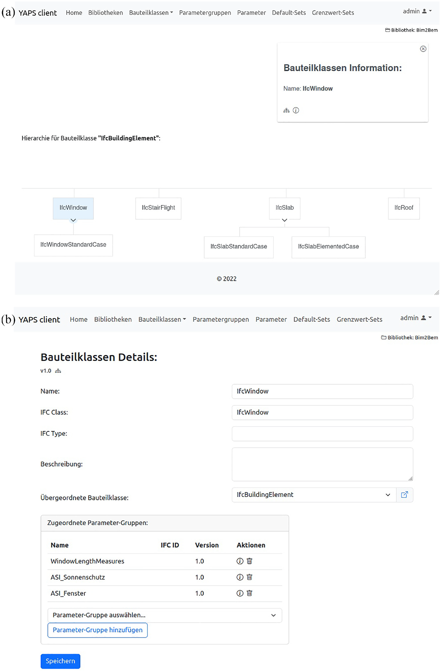
Building-part view of a window (a) with associated parameters (b). (a) Building-part hierarchy of a window as defined in the Property server. (b) Detailed view for parameter specification for the part from (a).
8.4. Model transformation engine
The Model transformation engine realizes model-2-model transformations using a generic rule mechanism (cf. Figure 11). The transformation rules are bidirectional as they run without information loss. Internally, our Model transformation engine employs Ecore 46 as modeling framework which provides the necessary genericity to support multiple BIM and BEM tools in terms of formalizing their metamodels using Ecore. Subsequently, the Model transformation engine parses the BIM model into its Ecore-based representation, applies the Mapping rules specified as part of the BIM2BEM workflow model yielding the Ecore-based BEM model. Finally, it generates the tool-specific BEM model from the Ecore-based BEM model. This approach is reminiscent of Model-driven architecture (MDA) that employs platform-independent and platform-specific models (PIM and PSM, respectively), where the PSM describes the model for a specific technology (e.g., a BEM tool), and the PIM in a way that is independent of any implementation, e.g., the internal, Ecore-based BIM or BEM models. Consequently, our Model transformation engine is not restricted to models in the AECO sector, e.g., BIM and BEM models but supports any model-2-model transformation given that the metamodels are expressable using Ecore which usually is the case. 46 Figure 16 shows a mapping of a parameter between the BIM tool Autodesk Revit (https://www.autodesk.eu/products/revit/) and the BEM tool DALEC.
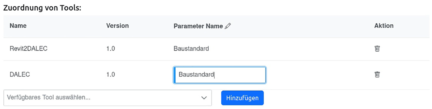
Parameter mapping between Autodesk Revit and DALEC as part of the workflow from Figure 14.
At a technological layer, the Model transformation engine uses the Atlas Transformation Language (ATL)51,52 and its underlying engine for rule execution and actual model transformation. ATL, in turn, uses Ecore natively to facilitate the handling of metamodels. 53
8.5. BIM and BEM tools
The BIM and BEM tools, such as Autodesk Revit and DALEC, are essential for creating a BIM model and subsequently conducting BEM simulations.
8.6. Dashboard
The dashboard is implemented using Grafana (https://grafana.com), an open-source data analysis and visualization tool. The simulation results that yield from the BEM tool are in CSV format which substantially eases data import for visual comparison with the aforesaid Performance goals. Figure 17 shows a screenshot of our dashboard after a simulation run with DALEC.
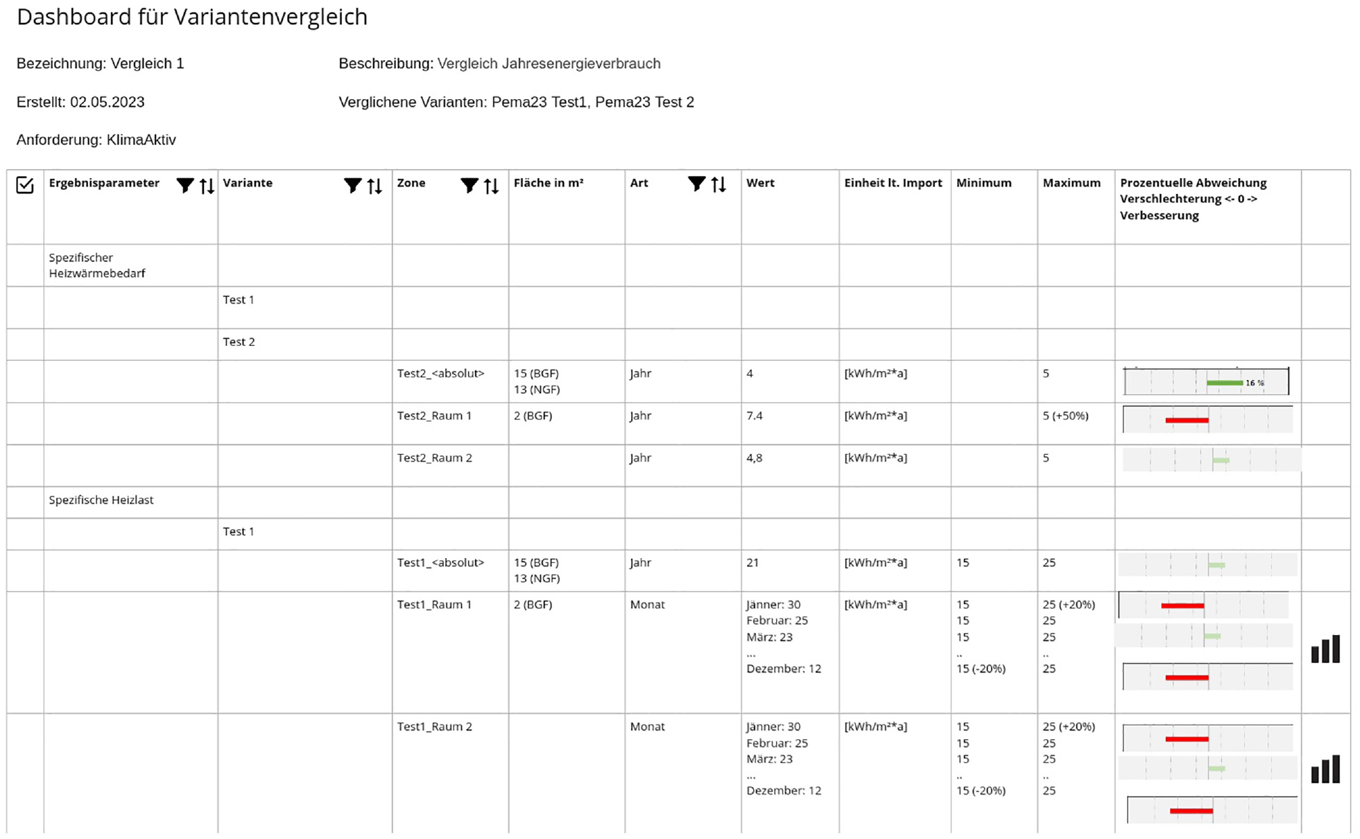
Result view of our Dashboard after a simulation run to compare different building manifestations.
As for the runtime environment of our proposal, besides a Desktop PC that is capable of running the BIM and BEM tools (Revit and DALEC), as well as the Model Transformation Engine as part of Eclipse IDE (https://www.eclipse.org), which implements the Ecore modeling framework and ATL, our proposal further requires a Linux server machine for running the BIM repository, the Property server, the Workflow manager, and the Dashboard. This server machine currently is deployed as a virtual machine with 32 cores running with an Intel® Xeon® Gold 5118 processor at 3.2 GHz with 64 GB memory.
9. Evaluation and related work
We evaluate our proposed tool environment using the Technology Acceptance Model (TAM) 54 for studying tool use in information systems (sections 9.1–9.4). Finally, we position our work concerning related work (section 9.5).
9.1. Evaluating and explaining tool use with the technology acceptance model
The TAM is a widely used theoretical framework for understanding and predicting the acceptance and usage of information technology and tools. 54 It was originally developed by Fred Davis in the late 1980s and has since been expanded upon by various researchers. 55 The TAM is particularly relevant for evaluating tool use as it provides a structured approach to assessing how users perceive and decide to adopt a technology or tool. In our work, we use a slightly modified version of the TAM as proposed by Riemenschneider and Hardgrave 56 and outlined in Figure 18. It comprises the following components:
Training
Perceived Ease of Use
Perceived Usefulness
Use
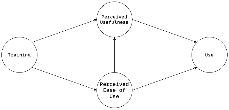
Modified TAM after Riemenschneider and Hardgrave with Training as an additional exogenous variable. 56
The TAM is of great significance in the assessment of tool utilization, as it offers a systematic framework for comprehending user perceptions, attitudes, and intentions pertaining to the adoption of technology. This comprehension has the potential to guide enhancements, contribute to informed decision-making, and increase the probability of successful implementation and utilization of tools within an organization or user group.54,55
9.2. Method
Given our earlier defined research questions (cf. section 4), we created a user survey to be administered to our sample. The sample in this case comprises selected representatives from the construction domain with both academic and industrial backgrounds. Specifically, after a demo of our tool environment which was followed by an individual evaluation by each of the participants w.r.t. their dedicated workflows, we administered our survey to the 12 representatives, among them, building designers (3), physicists (2), and control engineers (2), energy and thermal planners (3), and general contractors (2). The average age of respondents is 39.5 years with a reported average of 13 years of experience. Two participants did not disclose their gender; among the remaining 10 participants, there were eight males and two females. All participants received training in using the tool environment. The survey comprised the following question items:
The Likert-type scale used for all question items (except for
We are very much aware of the small sample size and its potential issues (variability, uncovered bias, voluntary response bias). However, as of its early prototypical state, we deliberately decided to make our tool environment only available to the consortium of the project. Yet, we plan an extended evaluation as soon as our prototype reaches TRL6 (cf. section 9.6). Nevertheless, the results of this initial small-scale evaluation (which should be treated with the necessary due diligence) are promising and fortify our decisions taken in developing our artifact.
9.3. Model evaluation
To perform a comprehensive evaluation of the adoption of our proposed tool environment, we employ a systematic approach to estimate and evaluate the associated structural equation model.
57
Structural equation modeling (SEM) is a valuable methodology for assessing intricate theoretical connections, particularly among latent variables. Two primary SEM approaches, namely covariance-based SEM (CB-SEM) and partial least squares SEM (PLS-SEM), have been introduced and are widely accepted.
58
In the present scenario, PLS-SEM proves to be particularly advantageous when the objective of the structural model is to forecast and elucidate the desired outcomes,
59
such as technological acceptance. The statistical computer language R version 4.2. was utilized in conjunction with the
9.3.1. Measurement model evaluation
Beginning with the assessment of the reliability and validity of our reflective measurement, following the methodology of Hair Jr. and Sarstedt,
61
we (i) evaluate the reliability of each indicator by examining their respective indicator loadings, (ii) analyze the internal consistency reliability using composite reliability
Regarding (i), all the loadings of the four constructs
9.3.2. Structural model evaluation
Having proved the reliability and validity of the constructs, we investigate the structural component of our instance of the TAM. Following Hair and Alamer’s
62
recommendations, we (i) examine the structural model for collinearity issues based on the variance inflation factor (VIF), (ii) assess the significance and relevance of the structural model relationships, i.e., the path coefficients, using bootstrapping, and (iii) assess the explanatory capability of the structural model using the coefficient of determination (R
2
) and the effect size (f
2
). Regarding (i), the VIF analysis reveals that our model does not exhibit any evidence of collinearity among the four constructs,
58
as the greatest VIF values are near the liberal threshold of 5.62,63 Regarding (ii), we assess the significance and the relevance of the structural model paths by bootstrapping the sampling distribution64–66 to test the structural model’s relationships coefficients for statistical significance at
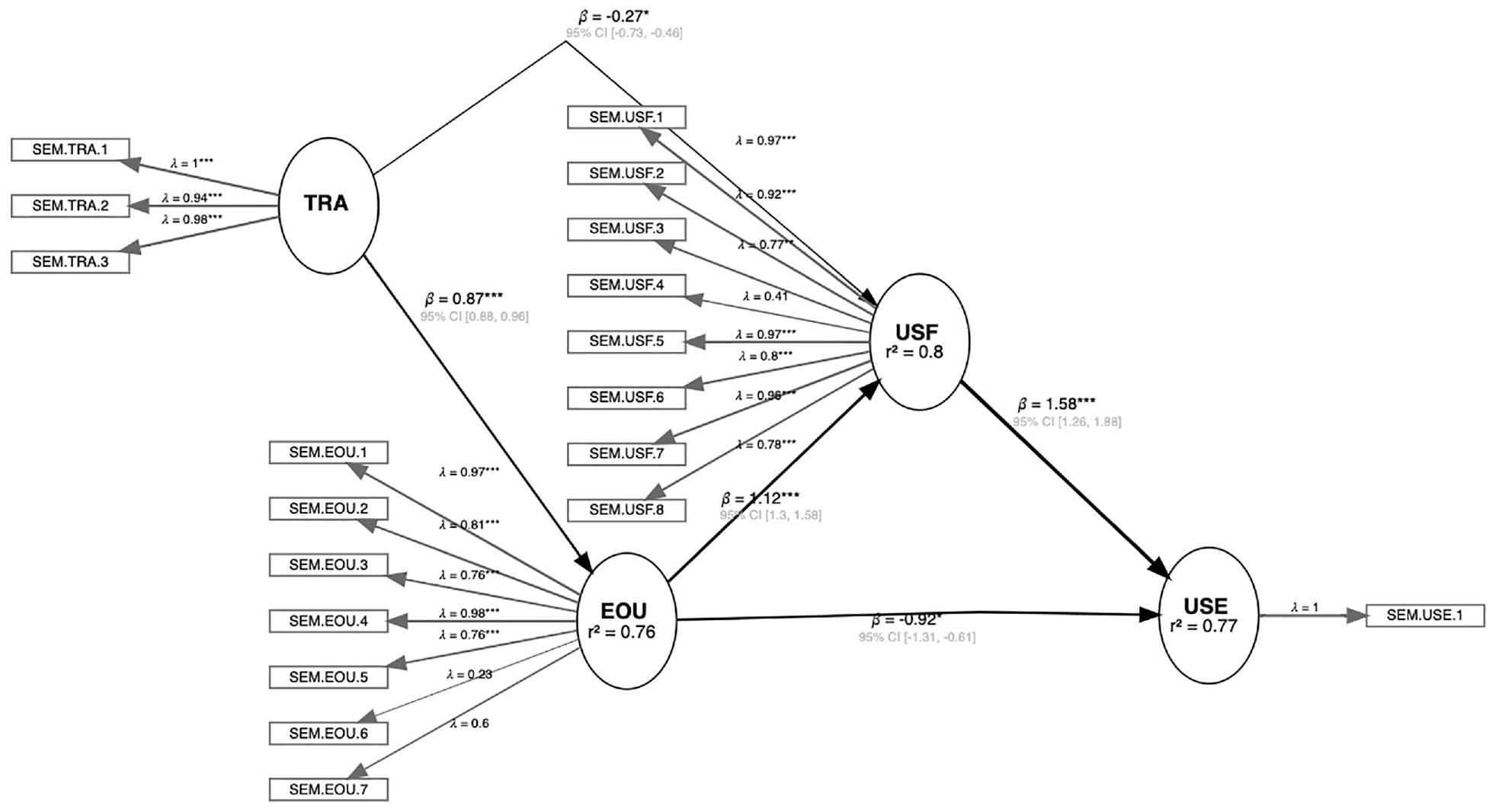
Bootstrapped PLS model. Values in ovals denote the
9.4. Interpretation of results
Our data analysis has confirmed the validity of our implementation of the
Regarding the construct
Regarding RQ1, viz. How to improve collaboration between experts in various trades for BIM and BEM? (cf. section 4), our model-based tool environment effectively showcases the utilization of MBTI to enhance collaboration by ensuring tool continuity across different trades and applied tools, i.e., BIM and BEM tools, thereby substantially capitalizing on the BIM repository.
As for RQ2, viz. How to implement an agile, continuous planning process for regressive building performance simulations? (cf. section 4), our modeling methodology, applied using our model-based tool environment, illustrates the process of capturing BIM (and BEM) model and tool requirements, and runtime objectives for a building, such as expected energy performance at an early stage in the planning and design process. Furthermore, modifications to any requirement or objective are promptly captured in the workflow model, enabling instant assessment through simulation. This clearly demonstrates the agility of our suggested approach by allowing for the prompt delivery of feedback, which closely resembles the principles of agile software engineering (cf. client feedback that is provided regularly after each iteration).
Finally, in the event of RQ3, viz. How to establish a foundation for tracing anticipated and actual energy consumption of a building throughout its entire life cycle? (cf. section 4), the combination of our model methodology for capturing building performance objectives as well as the underlying model-based tool environment for enabling the assessment of these objectives provides a solution. Specifically, by capturing and updating such performance objectives in the model for subsequent, regressive performance simulation to compare them with actual data from the building, our approach delivers the foundation for tracing anticipated and actual energy consumption in buildings throughout their life cycle.
As a final point, we want to briefly elaborate on reaching TRL6 as already mentioned earlier. Doing so primarily requires scaling up the usage of our tool environment to properly evaluate it in relevant environments. To this end, on one side, we will advertise our results as part of dissemination activities in the corresponding research project (cf. B2BF). On the contrary, our industrial partners in the project plan on organizing dedicated stakeholder workshops within their corporate networks to raise the awareness level of our tool environment and ideally expedite its adoption to improve collaboration (cf. model exchange) within their corporate networks. This in turn will require open sourcing our code base which usually also yields increased awareness.
9.5. Positioning to related work
Motivated by fundamental limitations in integrating BIM with BEM (cf. sections 3 and 4), recently early and initial work on tackling these limitations has been published. 42 For example, the work of Tagliabue et al. proposes a BIM2BEM workflow on the grounds of Autodesk Revit and IES VE as a BEM simulation tool. 67 Their approach, however, yields an immediate vendor-lock by only supporting one specific BIM and BEM tool combination without support for further tool integrations. In addition, their approach does not assure the presence of necessary building element properties for BEM. Pinheiro et al. 68 suggest the definition of a custom model view on a BIM model that merits building energy simulations. Specifically, the model view is defined along with the necessary BEM requirements that are needed for simulation. Similarly to Pinheiro, Miller et al. also suggest the definition of a custom model view on the BIM model for BEM simulations. 69 In contrast to our proposal, Pinheiro et al.’s and Miller et al.’s work, however, again only targets one BIM-BEM tool combination. Our approach allows targeting any BIM-BEM tool combination as long as the necessary model-based tool mappings are available.
Recently, Seidenschnur et al. put forward a proposal for common HVAC design and engineering. 70 Using a microservice architecture, they propose a scalable web application for integrated design. Their work investigates model sharing but does not delve into the subsequent applicability of the models for building performance simulation. Jeong et al. proposed a BIM-based workflow for thermal building simulation using Modelica. 71 They manually extend and convert a BIM model into a corresponding Modelica model for simulation. This manual creation of a BEM model is highly error-prone. A similar idea was proposed by Andriamamonjy et al., 72 yet for full energy simulation of buildings. By also requiring manual conversion of BIM models into BEM models, their approach suffers from similar issues as Jeong et al.’s. 71 Quite recently, Mediavilla et al. presented a graph-based approach for the synthesis of BEM models from BIM models. 73 Despite presenting an auspicious approach, their method does not yet consider dedicated BEM requirements and rather focuses on geometric aspects of BIM models.
MBTI has long been established in the software engineering community as a powerful mechanism for integrating various software tools and applications into a unified engineering framework by capitalizing on a common data model or a set of models that are connected via an underlying mapping mechanism.24,74–76 Crucially, MBTI addresses the system interoperability aspect of model-driven engineering in that it aims at enabling seamless collaboration using different modeling formalisms and platforms by unlocking tool boundaries.77,78 Major challenges at this are model heterogeneity which can yield information loss, versioning, and compatibility of both tools and models (and their metamodels), and general tool integration which usually requires the definition and implementation of additional standardized interfaces.77,78 Bruneliere et al. 79 presented a framework to bridge Eclipse- and Microsoft-based modeling tools in a unified framework by establishing mapping models among the different modeling levels (e.g., M3, M2, and M1, cf. Figure 2). Using model transformations, 25 models are transformed among these different representations. The work of Broy et al. presents a conceptual framework for MBTI comprising similar components to our proposal, viz. a model repository, modeling tools, a workflow engine, and a model interpretation engine for running model transformations. 80 Contrary to our work, Broy et al.’s proposal, however, targeted the embedded systems domain. Zhang and Møller-Pedersen proposed a framework for modeling tool integration on the grounds of the Open Services for Lifecycle Collaboration (OSLC) specification for software tool integration. 81 Specifically, their work aimed at providing a class-based modeling approach for specifying tool integration for the automated generation of code-based tool integration services. More recently, Mustacoglu proposed a novel model-driven framework for reaching a higher degree of interoperability among different software development tools coming from different technological spaces (TSs). 82 Mustacoglu establishes a mapping framework between modeling and model execution spaces using the ATL to specify the necessary model transformations. His work then again, however, only addresses integration of software engineering tools. To the best of our knowledge, the application of MBTI for the concrete use case of our proposal, i.e., enabling seamless model exchange between BIM and BEM tools for building performance simulations has not yet been investigated. We argue, however, that the benefits of MBTI (cf. improved interoperability, streamlined workflows, enhanced collaboration) merit investigating this avenue more rigorously in the future.
Our discussion of related work demonstrates the relevance of our contribution and the need for joint solutions that integrate technologies, i.e., BIM and BEM tools, with processes, i.e., an integrated (BIM and BEM) tool-agnostic workflow for BIM2BEM. 14
9.6. Threats to validity
This section addresses the primary factors that could compromise the validity of our study and the strategies we employed to minimize their impact per Wieringa. 43
9.6.1. Construct validity
Construct validity may affect both artifact construction and operationalization of constructs. For constructing our artifact, we followed an established research approach—DSR—to drive artifact design. In the course of this, we employed multiple actions to assure construct validity, viz. an expert review (cf. section 2), the meticulous inference and definition of the artifact (cf. sections. 5 and 6), prototyping and piloting (cf. section 8), and eventually employed a well-studied measurement instrument, viz. the TAM (cf. section 9).
9.6.2. Internal validity
Internal validity pertains to the degree to which the observed effects or outcomes in a study may be ascribed to the design of the artifacts or interventions, rather than external influences. Our evaluation shows that it is feasible to enhance collaboration among trades and establish integrated BIM2BEM workflows by ensuring tool continuity. However, we have only examined one specific combination of BIM-BEM tools (cf. Autodesk Revit and DALEC). To obtain more robust evidence, it is necessary to evaluate a wider range of tool pairs to determine which ones are less suitable for integration. To mitigate this threat, we want to assess supplementary tool integrations once our prototype achieves TRL6. In addition, in the course of this, we will re-evaluate the TAM with a substantially larger sample to substantiate the significance of our results.
9.6.3. External validity
External validity refers to the extent to which the findings of a study can be extrapolated and applied to different contexts. We recognize that our contribution was only evaluated in a BIM2BEM setting. To address this threat, one possible solution is to employ it for additional trades. By doing so, we can authenticate the outcomes of our DSR. There is no reason to presume that our contribution cannot be applied to further trades.
10. Conclusion and outlook
Driven by substantial conceptual and technological gaps in realizing integrated BIM2BEM workflows,13,14,33 in our contribution, we have proposed a model-based tool environment atop which we established an agile, continuous planning and design process for regressive building performance simulation. Capitalizing on MBTI and the BIM repository, we successfully establish tool continuity for seamless transfer of models among different trades for improved collaboration. The Property server in combination with the Workflow manager allows for efficient capturing and deliverance of BIM and BEM modeling requirements and design objectives, e.g., performance goals, throughout the complete building life cycle, thus providing a foundation for tracing and assessing anticipated objectives. The evaluation of our proposal using the TAM indicates high acceptance, thus qualifying it as a valid solution to our initially formulated design problem from section 4. On the grounds of our data analysis and its subsequent evaluation, we were able to successfully answer our research questions from section 4. In synopsis, our evaluation shows that our proposal facilitates the systematic construction of integrated BIM2BEM workflows for continuous and regressive building performance simulation along predefined requirements and objectives.
In the future, we plan on extending our proposal to further trades, e.g., artificial lighting and shading planning, in an attempt to move toward a more holistic simulation of building performance. This immediately comprises the integration and federation of additional simulations and corresponding tools. Observe that such a federation and integration of multiple simulations provides further insights that allow addressing novel research questions, e.g., automated clash detection between different trades. By combining workflow modeling and MBTI, our proposal provides a promising avenue in this direction.
Footnotes
Funding
The research leading to these results has received funding from the Austrian Research Promotion Agency (FFG) under grant agreement no.: FO999892959, BIM2BEM-Flow.