
Abstract
Container terminals are complex systems where containerized cargo undergoes a set of processing and handling operations to be delivered to their outgoing modes. A pool of decision support methods and simulation models has been developed to assist planners and managers in making decisions about daily operations. Nevertheless, most are designed for a particular terminal and not generic types. Indeed, a generic model serves as a conceptual factory to create specific models which greatly reduces the time and efforts of development; however, building such a model is no mean feat. To this aim, the paper on hand discusses the complexity of applying genericity, flexibility, and modularity in system modeling and proposes a generic architecture to build modular and flexible simulation models for container terminals. This architecture is split into a set of smaller, manageable, well-connected, and generic modules that facilitate the creation of highly parametrized specific models. An illustrative example of the architecture usage is presented in a case study, the new container terminal of Stockholm, and the resulting models were validated by subject matter experts. Finally, to prove its efficiency, a numerical study fed with real data is conducted to investigate the handling capacity of the studied system under different handling and flow scenarios. The obtained results show that the terminal handling capacity can be increased by around 50% if three to four more straddle carriers are added to the existing fleet.
Keywords
1. Introduction
Container terminals, being a complex system, have a stochastic and dynamic behavior along with a high level of interconnection and interdependency among their components, evolving in an uncertain environment. Therein, containerized steel boxes are subjected to a set of processing and handling operations (security and weight checking, scanning, loading, unloading, and storage) to be delivered on time to their outgoing modes (trains, trucks, ships, etc.). This panoply of operations is usually performed by multiple types of equipment (quay cranes (QCs), straddle carriers (SCs), reach stackers (RSs), etc.), and sometimes planned under a lack of information needed for sound planning which may lead to some undesirable situations (delays, rehandling, unproductive waiting, congestion, etc.). In addition, the stochastic aspect of this system, and seaports in general, stems also from the unforeseen perturbations and risks that can arise after human errors or other disturbing factors (e.g., weather).
Such complexity makes it intrinsically difficult to predict system behavior, hence the interest of studying these systems to come out with relevant solutions to assist in solving the existing complicated problems, and simulation as a method to support design and decision-making has had significant impact already. In container terminal literature, most simulations and models are designed to cover the specific aspects and problems being studied. This paper follows this direction but also proposes a smoothly adjustable architecture whose scope can be easily adjustable to cover further features.
The remainder of this paper is structured as follows. Section 2 describes the objectives behind the study and the main contributions of this paper to the body of knowledge in tandem with the problems under focus. This is followed in section 3 by a brief literature review that stresses the limitations of the existing simulation models and tools. Section 4 exposes the proposed architecture and its application on the new container terminal of Stockholm. In section 5, the verification and validation (V & V) process are presented, and a numerical study is conducted to investigate the handling capacity of the studied system under different handling and flow scenarios, then the obtained results and the generic properties of the designed architecture are discussed. The final section summarizes this paper and highlights the future improvement and works.
2. Background and problem statement
2.1. Scope and aims
The case study for this paper is a new container terminal of Stockholm (see Figure 1). This terminal includes a seaside where ships are unloaded and loaded by QCs and a hinterland side composed of road and rail sub-sides where trucks and trains are handled by SCs and RSs, respectively. Container flows entering from both sides are stacked temporarily on the top of each other by SCs in the internal yard.
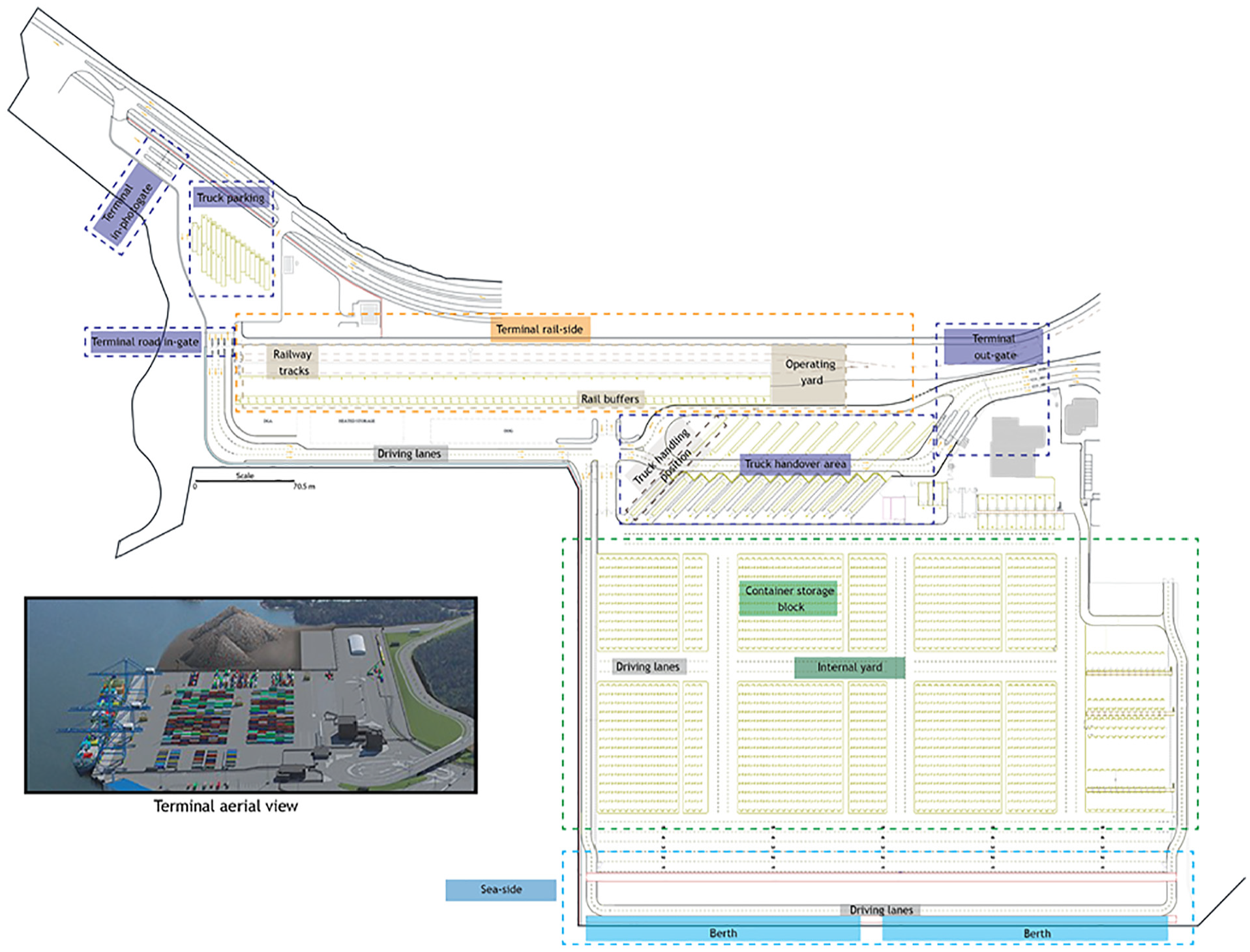
The new container terminal of Stockholm: Norvik seaport.
The aim was at first to analyze this system by the means of a simulation model that is able to provide beneficial assistance to decision-makers. So, the model to build should be able in the first place to support a wide range of solving approaches while allowing a freedom of acting on the virtual representation and choosing the way in which the best solutions are determined. In the second place, to point out potential problems in terminals planning (such as bottlenecks, congestion, deadlocks, unproductive waiting, delays in handling, reshuffling, and over/under use of resources), and to allow the evaluation of the issued plans and schedules under different scenarios and perturbations (pavement and infrastructure failure, human errors, etc.) with a real-time monitoring on handling times and facilities utilization.
At the early stage of modeling, the conducted literature review revealed the existing similarities at the operational and physical level between certain kinds of terminals, and the idea of a potential model able of supporting different layouts and operations emerged. Thus, the spotlight has broadened to cover up this direction too in order to design smoothly adjustable conceptual models. This is advantageous at the practical level but also at the conceptual level. That is, having such a model or at least the design at hand will be helpful in future in case the focus is redirected to study another terminal type.
To this end, this paper addresses the problem of designing such a model by proposing a generic and scalable architecture to build modular and flexible simulation models for container terminals and proposes a method that can help planners to determine which solutions fit their requirements and expectations about daily operational performance. Then, the handling capacity of the studied system is investigated under multiple handling scenarios in order to first determine the needed resource for ensuring an efficient and smooth evacuation of different sizes of incoming flow, and second identify how more traffic could be caught with respect to layout constraints.
However, performing accurate evaluation of system performance is related to the precision of outcomes which increases when the abstraction level decreases, so our models must be a microscopic representation of the studied systems (i.e., low level of abstraction is chosen). Nevertheless, representing some parts of reality could be worthless because either they will have no significant impacts on the desired outputs or they can be aggregated into simple forms to reduce the complexity of the design (i.e., driver behavior). Risks within seaports can be categorized into two types: first, regular risks such as delays, equipment failure, and pavement cracking, and second, irregular risks such as explosion, leakage of toxic liquid or gas, and natural disaster. In this study, the latter type is not considered.
2.2. Methodology
Simulation modeling is the appropriate approach in terms of system characteristics as well as the purposes behind the study in order to perform accurate assessment.1,2 In fact, simulation models (computer simulation), as stochastic by nature, are typically designed to imitate the system behavior as much as it is potentially possible. The end-user enjoys the freedom to act on the virtual representation by introducing, for instance, new policies, perturbations, and scenarios, and then analyze their impact on system performance. In addition to the freedom of acting, the randomness is an intrinsic feature in simulation models implemented through probability functions.
In spite of that, designing simulation models for complex systems is no mean feat, and a road map to simplify the designing process is strongly needed. In the literature, there is no agreement on particular designing approaches.3–5 Nonetheless, most of them could be staged into four steps: inception, analysis, conception, and implementation. Moreover, the conception of a simulation model may depend on three influencing factors: (1) system designer awareness and perspective, (2) the nature of the studied system, and (3) the desired abstraction level. The four designing steps used in this study are shown in Figure 2, that start from requirements definition down to model implementation through formalized artifacts linking steps to each other. A full explanation of our methodology can be found in Abourraja et al. 6 At the initial stage of the simulation building process, we draw a broad picture of system functioning then delve deeper into features and components that are under investigation in order to end with a trustful and well-refined conceptual model easy to implement. This process is iterative because one can notice that certain insights included in the previous step are incomplete, unclear, or erroneous. In other words, the forward and backward transitions over the steps refine the model to be more realistic. It must be noted that the modeling activities in each step could be carried out in parallel or sequentially. The designing steps are defined as follows:
Inception: here, the issue is about capturing and collecting details that are relevant to setting up models fitting with designing purposes.
Analysis: in this step, the core concern is to delve deeper into features and components of our studied systems so as to reach lower abstraction on its dynamic and draft a preliminary simplified representation.
Conception: this step dives deeper into the creation of the simulation model. More details on this step are given in the next section and section 4.
Implementation: this step concerns, on one hand, the coding, debugging and running of the model, and on the other hand, the validation and verification to end with a trustworthy tool ready for usage and exploitation. More details on this step are given in section 5.
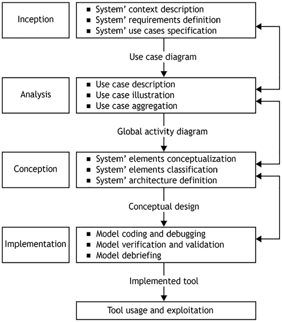
Methodology.
2.3. Issues under focus
This section exposes the problems that we encountered while trying to apply generic, flexible, and modular principles in building consistent and robust models for container terminals by answering this research question: “how to design a generic-modular model with high flexibility?”
In general, fairly similar systems share common features and differ in others. The first ones could be named as “commonalities” and the last ones as “variabilities.” 7 Both of them need to be clearly identified to build a generic architecture for a group of systems which can serve later as a conceptual factory to create specific models. Consequently, the first issue is to define the generic skeleton for the considered category of systems that includes the general physical form (i.e., the layout), the generic abstractions of the common features (e.g., properties, behaviors, operations, and planning), the variation points where the differences can be specified (i.e., the characteristics that define a specific type of terminals), and the patterns of relations between all of these elements (e.g., data, knowledge, requirements, constraints, events, transitions, and synchronization).7,8 However, we should not lose sight of the fact that any architecture has limits (e.g., the considered aspects, the degree of the abstraction level, and the unsupported system types). 9 Indeed, each architecture is built around a firm skeleton which prevents the extension of certain of its basic features, could be named as model’s kernel, to satisfy, for instance, certain particular needs (e.g., increase the degree of the represented reality). Therefore, the second issue is to find a tradeoff between the degree of model’s kernel inflexibility and the expansion of architecture features, i.e., the degree of scalability.
The expansion (i.e., introducing extra functionalities) and the extension (i.e., inheritance) are forms of architecture flexibility through which more particular requirements are captured. Extension is a well-known and defined mechanism as it consists of deriving new features and components from the existing ones, which means that the new elements will still be under the umbrella of model’s kernel boundaries. Conversely, expansion is about making changes in the structure itself which is de facto not easy to implement. An appropriate mechanism of achieving such flexibility has to be defined in accordance with the kernel boundaries in addition to plainly specify what kind of changes is supported and what is not. The flexibility also refers to the ability of the model to adjust itself and to produce different behavior as a result of tuning up its features’ settings, and to enable a wide range of possibilities. Furthermore, flexibility is also the degree to which the designed generic architecture is reusable. 10 Reusability is the concept of designing features and components that can be reused in different situations which much help to extend the lifespan of architecture usability. Therefore, it is also important to deeply analyze the commonalities and variabilities of the target system family in an attempt to reduce the architecture inflexibility so as to grant a high level of reusability.
Modularity concerns the reduction of large systems’ complexity by way of splitting the whole into a set of smaller and manageable parts which may also be composed of sub-parts and so on. These parts are usually constructed with homogeneous components and often have a varying degree of connections between each other. This can also be seen as a form of model flexibility. Complex systems are where highly interrelated and varied components evolve toward achieving individual or collective goals. Then, the challenge lies first in subdividing the architecture into coherent parts (i.e., sub-models) with distinct roles that act as a cohesive whole. In this line, the roles and functionalities of system components need to be properly analyzed to come out with distinct classes of roles which help in components’ segregation. The second challenge is defining the interdependencies among the sub-models without impacting their flexibility insofar as possible. High dependency between certain components of the reference system may, however, limit this flexibility. For instance, system’s operations take place on system’s infrastructure, and both of them are governed by system’s decisions. To sum up, the use of these principles makes the conceptualization a bit laborious but simplifies the upgrading and maintenance of the model, reciprocally the tool.
This paper tries to bring all these principles together in a functional system by establishing a novel generic, modular, and flexible architecture obtained through meticulous analysis of the studied system family that helped us first in identifying commonalities and variabilities necessary for the development for reuse and second in splitting the designed system in a set of homogeneous sub-models, hereinafter referred to as modules. The next section shows the low interest of the literature to the use of these principles for making simulation models.
3. Literature review
In this section, a brief review on decision support methods based on simulation and simulation models for container terminals is reported to highlight the main novelties of this paper. A great body of container terminals’ literature has been formed over decades. Literature surveys on terminal operations and layouts are given in Stahlbock and Voß, 11 Boysen et al., 12 Carlo et al.,13,14 Bierwirth and Meisel, 15 and Gharehgozli et al., 16 and are not detailed in-depth here.
The undertaken literature review showed that discrete event simulation (DES) is the widely used simulation approach for both prediction and investigation of container terminal performance from different perspectives, and it could be used lonely or combined either to multi-agent systems (MASs) or to system dynamics (SD), although the use of SD in simulating terminals is quite rare.17,18 Moreover, since the tremendous leaps in computational power, simulation models can integrate optimization models or on the contrary being embodied inside optimization models or otherwise both could run sequentially. Bae et al. 19 outlined the different ways of combining optimization with simulation as well as optimization/simulation with other methods, and a full review of these combinations is done by Figueira and Almada-Lobo. 1 According to these authors coupling simulation with optimization is an appropriate way of solving complex problems within a stochastic environment; however, the traditional practice of using analytical models in optimization still dominates. 20
Simulation modeling is applied for both designing and analyzing logistic systems without mathematical sophistication and has easily found its way to container terminal applications, yet most of them are built to investigate a single area of the terminal and have been set for a particular terminal type which can be explained by the defined objectives behind the study and the extreme complexity of dealing with the whole system. In the seaside, Petering 21 investigated the impact of the capacity of dual-load yard truck and fleet composition on the long-run average QC throughput using a DES model of pure vessel-to-vessel transshipment terminal. Rouky et al. 22 designed a hybrid optimization–simulation approach to solve QC problem in stochastic context where the handling and travel times of containers and equipment are considered uncertain. Most notably, at the seaside, much effort was spent on solving QC problem. 23 In the internal yard, Guldogan 24 proposed a simulation-based analysis for hierarchical assignment policies for container storage. Likewise, Sharif and Huynh 25 studied storage space allocation problem, but their simulation model used ant-based control method instead. In general, the capacity of the storage space is of paramount importance for logistics platforms, so it should be managed carefully to avoid undesirable situations. 26 In the hinterland side, Boysen and Fliedner 27 and Boysen et al. 28 dealt with gantry crane scheduling in the operating yard with consideration to crane interference and deadlock situation problems, while Sadeghi et al. 29 evaluated container processing at the railside using various simulation scenarios to identify possible bottlenecks during handling operations.
As concerns the whole terminal, Bielli et al. 30 elaborated an object-oriented based DES for the container terminal of Casablanca, Morocco. The aim of this work is to find the best ways of managing the incoming flows by exploring different handling policies. Likewise, Cartenì and de Luca 31 conceived several microscopic DES models for different equipment in containers terminals. These models have the same activities of physical flow management but differ in the distribution functions used to estimate the duration of handling. The models were compared to the observed real data by analyzing the so-called local and global performance indicators to come out with the best one. Clausen et al. 32 developed an object-oriented based simulation tool called “ContSim” for container terminal management which allows in addition to material flow simulation, the simulation of the information flow in order to determine to best mix of operating strategies. Regarding layout design problem, Liu et al. 33 developed simulation models to investigate different maritime terminal configurations in terms of costs and operational performance. In this line, Lee et al. 34 simulated various alternative configurations to a rail terminal, while García and García 20 built a simulation-based flexible platform to study strategic and tactical decisions related to rail–road terminal design. For the same issue but within multi-yards rail–road terminals, Chen et al. 35 established a modular and flexible simulation framework to provide a quantitative evaluation for the specified terminal layout. This framework is arranged in four layers: the first and second layers contain the DES models and the core of the simulation, respectively, and the third one is where the layout is defined and the final one is the user interface where framework settings are set.
In the aforementioned papers, DES has been used nonetheless exploiting only the toolbox of DES method allows only complex systems to be represented at a mesoscopic abstraction level, because the individualities of systems’ actors cannot be caught. 36 In addition, using object-oriented modeling is not suitable to model active entities such as equipment and transportation means, since object refers to passive entities. For these reasons, agent-based modeling is recommended to be used.37,38 Coupling DES to MAS gives birth to multi-agent–based simulation (MABS). Here, the interactions and individual behaviors of system actors as well as the management of operations are described with MAS while handling processes are drawn as discrete event flows which offer a near-realistic and microscopic representation of the system. Fotuhi et al. 39 modeled yard cranes as reinforcement learning agents and used safety spacing constraint to guarantee collision avoidance. Abourraja et al.40,41 presented two agent-based strategies for gantry crane scheduling at rail–rail transshipment yard, the first one used ant-colony algorithm to model crane behavior whereas the second one used what-if rules. Garro et al. 42 addressed SC scheduling issues in container terminals using MABS combined with mathematical models.
In the thesis of Henesey, 38 the author developed several strategies based on MAS to deal with different problems in container terminals. In the same perspective, Yin et al. 43 introduced an intelligent MAS for terminal planning and scheduling masterminded by a supervisor agent who manages the whole system and coordinates communications and activities among system agents. Sun et al. 44 exposed a modular and flexible simulation platform based on MAS called “MicroPort” composed of three layers: (1) the functions layer, as the basis for the platform, contains the basic elements to support the higher layers, (2) the application layer, as the brain of the platform, where is settled the MAS that guarantees the well-running of terminal’s processes, and (3) the extensions layer, as the interface with the users, where outputs are displayed and settings are set. In Sun et al., 45 the authors extended the previous platform to study the extension of mega-container terminal layout. Similarly, Abourraja et al. 46 adjusted the model designed in Abourraja et al.40,41 on a rail–road terminal in view of studying the layout design problem, besides the system was connected to the optimization model of Benantar et al. 47 to schedule the arrival of trucks.
As can be seen from this literature review, it is clear how beneficial and important is the simulation in decision-making. Many interesting models have been proposed for diverse purposes; nevertheless, none of them combined the discussed principles in their architecture, except, as far as we know, Sun et al., 44 but they focused only on seaport container terminals and did not show whether their model is adjustable for particular needs. Another remark is that little attention has been paid to the impact of handling operations on the infrastructure and most papers investigate only a single area of the terminal. Therefore, the paper on hand tries to fill this gap and contributes toward the theory of modeling by showing how the outlined concepts and principles as well as the modeling practices can be used together in the design process. To sum up, the main novelty of this paper is introducing a novel generic-modular architecture with high flexibility to build simulation models for container terminals, having such architecture at hand will help in future projects about other terminal types, thus the modeling efforts and times will be reduced by a lot as well as the upgrading and maintenance will be easier. The other contributions of this paper toward the body of knowledge are summarized as follows:
Proposing a helpful way to determine which solutions fit with planner requirements and expectations about daily operational performance.
Presenting models that consider the impact of handling operations on the infrastructure (e.g., road and pavement).
Investigating the handling capacity of the studied system under different handling and flow scenarios.
4. Architecture for container terminals’ simulation model
4.1. Foundations and elements taxonomy
After the literature review, a general picture on container terminals functions and composition has been drawn. Generally, a terminal’s operator plans handling operations and manages resources according to the upstream information received from transport service providers (TSPs) (shipping lines, inland transporters, etc.). This information contains a detailed description of the incoming flows, namely, loads and loading plans of transportation modes, the content of containers, the origin and destination, the arrival and departure dates, and so on. There are three types of flow: import flow, export flow, and transit flow (i.e., trans-shipment of containers among same-type mode). The coordination of these flows is the role of TSPs as the major actors of the supply chain. As concerns operations and resources, each of them is related to one or more decisions in order to be assigned to specific internal actor (handling equipment or terminal workforce) or external actor (ship, train, truck, etc.), respectively. Operations produce damage on resources while being influenced by certain factors, such as environment vulnerability, human behaviors, and risks, so undesirable situations may occur causing degradation of operation performance (bottlenecks, delays, equipment failure, reshuffling, etc.). This performance is seen through key performance indicators, often abbreviated to KPIs, allowing terminal operators to supervise operation progress and to get feedbacks about their decisions. They concern mainly times, moves, resource utilization, energy consumption, and costs (other KPI could be identified).
In this study, we used a functional and organizational decomposition philosophy to divide up the target system. In the first place, all abstract roles representing distinct categories of homogeneous executable roles are defined. For example, handling can be seen as the abstract parent of loading and unloading, and maneuvering as that of coupling and decoupling, but since handling and maneuvering are both about operations so all of their offspring are grouped under the umbrella of “operating” while keeping, of course, the enrollment of offspring in their sub-category. Otherwise, other elements could also be gathered following their real location inside the system. In the second place, each element should have a unique specific role in the system during its all lifecycle. If an element is playing more than one role, it should be split into sub-elements which make the model gains in detail. For instance, a train transports containers and routes railcars, so it is modeled as a set of wagons transporting containers hauled by a locomotive. Differently, in some cases, the splitting of double roles elements makes no logical sense. SCs carry out loading, unloading, and transportation of containers but actually there are no logical sub-elements of SCs, in addition transporting and unloading are both a kind of container moving. This decomposition philosophy promotes the creation of easily manageable modules composed of homogeneous elements.
From the above sections, the following abstract roles can be distinguished in the target system family: operating (operations), planning (decisions), feeding (flows), displaying (KPIs), and supporting (facilities and equipment). In the light of this, the architecture is cut down into five main modules: operating module, planning module, TSP module, dashboard module, and resource module (see Figure 3). The last one contains two sub-modules: entity module (facilities) and actor module (equipment). This composition is also motivated by the desire to allow wide flexibility to the tool to adapt to different types of terminals. As can be seen from Figure 3, the main modules are assigned to three levels. The lower level is the backbone of this architecture as it provides raw material to the upper levels. The medium level reproduces terminals’ operations and planners’ behaviors in addition to the stochasticity of the environment. An operation is subjected to a decision and supervised through KPIs while being executed; this strong relationship is behind wrapping operating, planning, and dashboard modules at the same level. The upper level holds the module in charge of making physical flow (container, transportation modes, etc.). As stated previously, TSPs have the upper hand on the synchronization of the physical flow and its route through terminals, so it seems logical to put TSP module at the upper level. In brief, the medium level is the mastermind of the proposed solution fed with physical flows generated by the upper level and is aware of its context via the lower level. Similar multi-layer structures for logistics systems can be found in: Sun et al., 44 Chen et al., 35 and Bae et al. 19
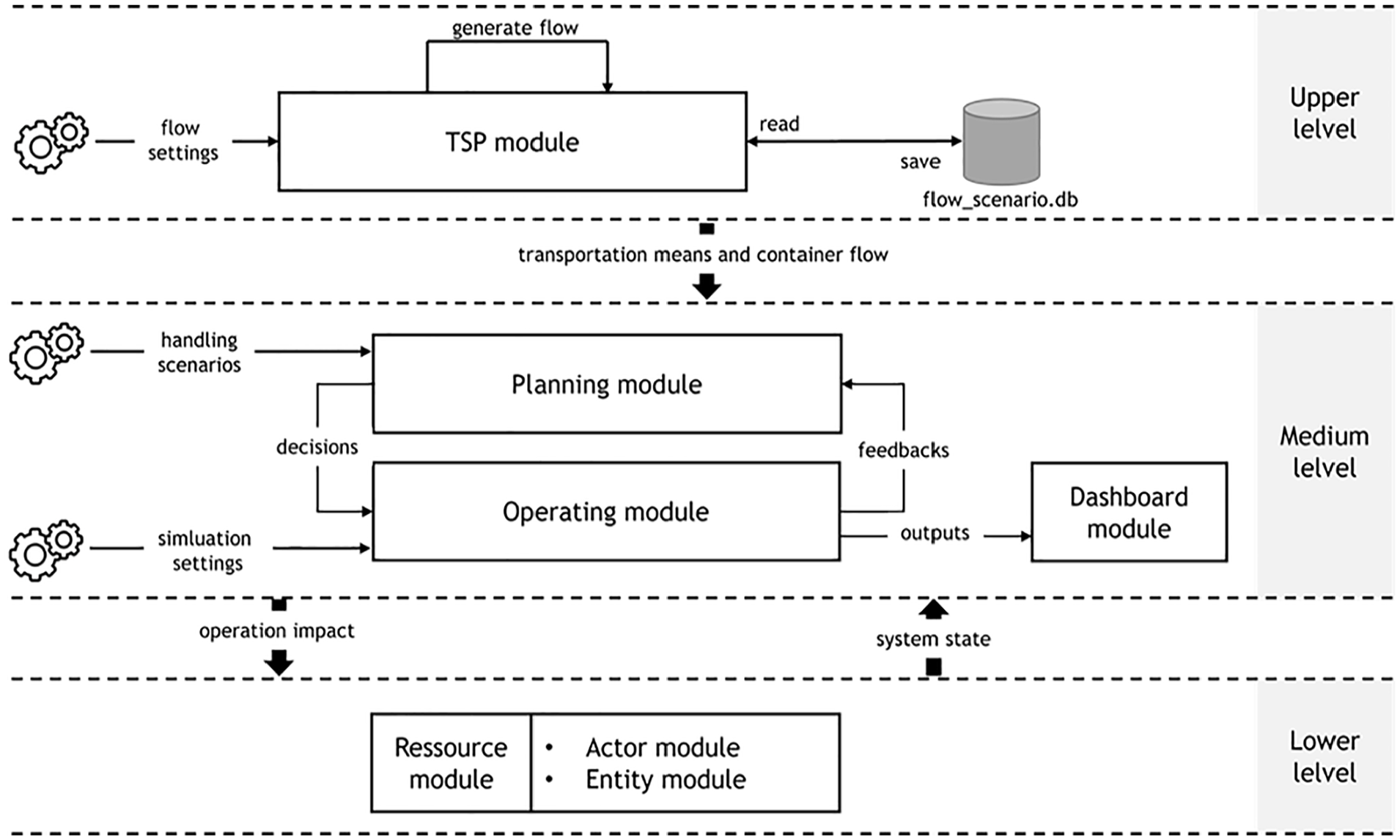
The proposed architecture.
TSP module creates and saves flow scenarios either in files or in databases regardless of the body in which it is involved. However, in case when old scenarios or other ones (e.g., created manually) are used, there is no need for the engine of TSP module, because it will be solicited only to inject transportation means inside the system through the dedicated connecting interface which will reduce a bit the execution time. With regard to dashboard module, it displays model outputs by listening to the operations and processes and it does not generate any feedbacks. Planning and operating modules are strongly related to the resource module. As said, system operations take place on system infrastructure; besides, they can be fed with schedules and plans generated by the planning modules or built manually. Whereas, decisions need to know the related actual context in order to work out operating plans and schedules properly. As the new container terminal of Stockholm is our studied system, it is the illustrative example of the proposed architecture in the next sections.
4.2. TSP module
The role of this module revolves around the generation and synchronization of the physical flows over the simulation period (simulation start and end date, opening and closing time, holidays and working days in the week). This module is inspired by the work of Hartmann. 48 The TSP’s engine consists of these main elements:
Flow, Size, Type, and TransportMode: Enums that illustrate the supported flow type (Import, Export, and Transit), container box-size (TEU: Twenty-Foot Equivalent Units, FEU: Forty-Foot Equivalent Units, and OOG: Out Of Gauge Cargo), container box-type (Standard, Reefer, and Tank), and transport mode (Ship, Train, Barge, and Truck), respectively.
ContainerFlow: where the container flow distribution is defined: average volume per day, flow distribution, box-size and box-type distribution, dwell-time distribution, weight distribution, origin–destination matrix, and upstream and downstream distribution over transport mode.
TransportModeScheduler: it is an abstract class where the arrival timetable of transportations means is specified. A TransportModeScheduler is designed for every supported mode. This class is composed of:
TransportModeCategory: it is an abstract class to indicate the capacity, speed, dimension, and category name of transportations means. ArrivalPattern: it is an abstract class used to define the number of arrivals per time slot, arrival–departure rate, and estimated staying time. In truck arrival pattern, the following parameter is added: filling distribution, i.e., how many trucks come, leave reciprocally, with or without containers. TimeSlot: it is used to divide the working day in time slots. TimeTable: it sets out all the ArrivalPattern of a specific mode’s categories in function of TimeSlot, i.e., TimeSlot X TransportModeCategory → ArrivalPattern.
All of the depicted classes are extensible to produce a wide range of scenarios except Enums because they specify the boundaries of this module.
4.3. Resource module
This module communicates information on the actual situation, the availability, and the quantity of terminal resources. Terminal resources can be classified into two classes: equipment and facilities. Equipment are active entities modeled as agents having goal-oriented behaviors to be able of acting and interacting with the environment and other entities. Whereas, facilities are reactive entities modeled as dynamic objects without any awareness of their environment but having stimulus–response behaviors to constantly change their internal state (physical condition) in consequence of actions done by an agent.
4.3.1. Actor module (agent-based modeling)
This sub-module is linked to the role of “executing” to reproduce the behavior of equipment, transportation means, and labors. Therefore, agents can be classified into six relevant types: 11 driven unit, handling equipment, traction equipment, transport equipment, labor, and transport means (handling equipment, traction equipment, and transport equipment are derived from the abstract agent equipment). This classification of agents is an effort to reflect the real nature and attitude of actors inside the terminals:
• DrivenUnit: it represents driven agents that are unable to move by themselves: containers, chassis, and wagons.
• Equipment (parameters: capacity, failure rate, safety distance, energy consumption rate, etc.):
○ HandlingEquipment (parameters: spreader speed, hoisting speed, time to pick-up/drop-off containers, etc.): it takes in charge of loading and unloading (lifting up and down) of transportation means, the storage and retrieval of containers as well as the transportation of containers. The instantiable agents of this type are QC, SC, RSs, forklift, yard crane, and rail gantry.
○ TractionEquipment (parameters: de-coupling time, etc.): it carries out these operations: parking and moving of passive units. The existing traction equipment are tractors and locomotives.
○ TransportEquipment: agents performing only transportation of containers, namely, AGV and internal truck.
○ Labor (parameters: working speed, etc.): it represents the workforce, namely, maintenance agent who repairs pavement and equipment, and customs.
○ TransportMeans (parameters: capacity, etc.): agents delivering and collecting containers to/from terminal which are ship, barge, train, and external truck.
Some agents are combined to stand as a coherent unit. A train is composed of wagons hauled by locomotive as well as a truck is a set of chassis dragged by a tractor. All agents possess basic behaviors such as moving, listening, and sending, but equipment agents have an additional behavior illustrated in Figure 4. At the beginning, equipment agents are at the operational state; however, they can transit at any time to failure state according to the failure rate. When it happens, the concerned agent throws an event to inform the system about this emergent situation. The planning module then makes the required re-planning and orders to the maintenance agents to start the repair. At the same time, the operating module moves the equipment aside. Once it is put into service again, the equipment returns to its initial state. This sub-module contains the most known and used equipment in containers terminals. Of course, other agents can be introduced into the system through the inheritance principle.
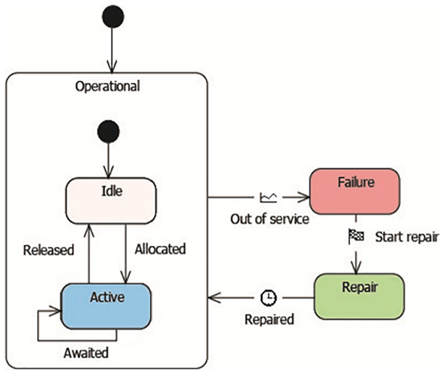
Equipment behavior.
4.3.2. Entity module (object-oriented modeling)
This sub-module exposes the way the infrastructural resource of the terminal is virtually represented in terms of object-oriented concepts (see Figure 5). The facilities are either employed as receiving positions for agents or as operating area where operations take place, that is why the abstract role behind this module is “holding.” Broadly speaking, a terminal consists of one or two operating interfaces and/or an internal yard; the whole is interrelated by a network of paths. The interface is the zone where transportation means are received and served. Most terminals have two interfaces: one for the upstream and the other for the downstream. But terminals that ensure only trans-shipment of containers between the same transportation mode have only one interface for both streams (e.g., vessel-to-vessel transshipment terminal, and rail–rail terminal). The internal yard is used to accumulate containers within a set of blocks or lots. Likewise, pure trans-shipment terminals might not have an internal yard since buffers or waiting areas in the operating interface are used instead (e.g., rail–rail terminal and rail–road terminal).
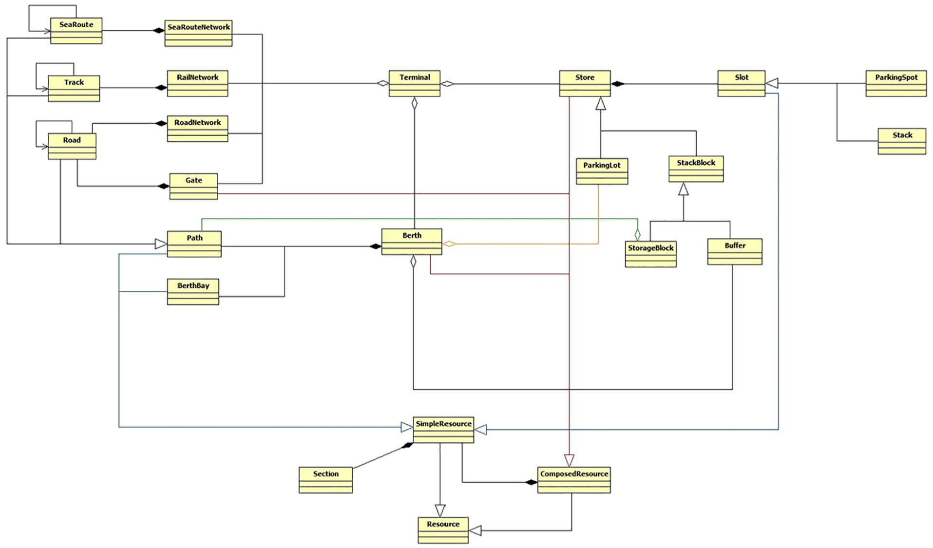
Class diagram for container terminal facilities.
A typical class diagram of a container terminal is given in Figure 5. The class Resource is the superclass of every facility and has two direct offspring SimpleResource and ComposedResource. A simple resource does not encompass other resources while a composed resource does. The body of a simple resource is a set of sections used as the basic element of terminal physical infrastructure. The section class is equipped with a “finite-state machine,” which can be seen as a behavior, similar to that of equipment agents (Figure 4). A section is able to measures constantly the degradation caused by operations (moving, dropping-off containers, storing, parking, etc.) on the basis of the applied force or the degradation rate over time. When the section exceeds its endurance threshold (the physical condition index is under the minimal value), it shifts to failure state, whereupon an exception is thrown to inform the operating and planning modules. Then, the maintenance agent is called to return the damaged section to its original condition. The other main abstract classes are as follows:
Store: it represents parking lots and storage spaces, and it is composed of a set of slots.
ParkingLot: it represents waiting area, parking area and transfer positions.
Berth: it is where ships are loaded and unloaded.
Network: it networks connecting the different parts of the terminal.
4.4. Planning module
In this study, decisions are classified as shown in Table 1. Tactical and operational decisions are about resource allocation and management, equipment deployment and scheduling, and yard assignment. Strategic problems are not considered in this paper. More details about decisions and planning problems can be found in: Boysen et al. 12 and Carlo et al.13,14,23 The pillars of a decision are as follows: boundaries, parameters, inputs, triggering events, and outputs. Boundaries define the scope of the decision through three wildcards: R (refers to the resource managed by the decision), A (refers to the type of resource asker), and P (refers to the type of issued operating plan). Parameters are the settings defining the decision behavior as well as the knowledge through which it perceives the related context, environment, and problem. Inputs are the feeding data (e.g., connected decisions’ established plans, involved actors, and extra knowledge) whereas outputs are the operating plans resulting for the concerned actors. Both these fields link decisions together to form a multi-directional chain since the outputs of prior decisions could be the inputs of the subsequent ones. With regard to triggering events, they set off the decision once occurring like the arrival-departure of transportation means, the release-seize of resources, the reception of a message, the achievement of a process, timeout, manual calling, and so on.
Classification of decisions and operating plans.
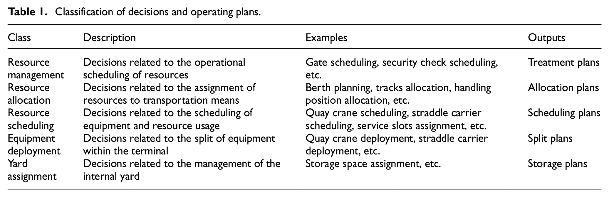
Figure 6 presents the planning module designed for the container terminal of Norvik port, and how decisions are interconnected while highlighting the dependencies and the stream of data that flows among all decisions. The displayed decisions are for the available equipment in our container terminal, namely, QCs, SCs, and RSs, in addition to the considered transportation modes: ships, trains, and trucks.
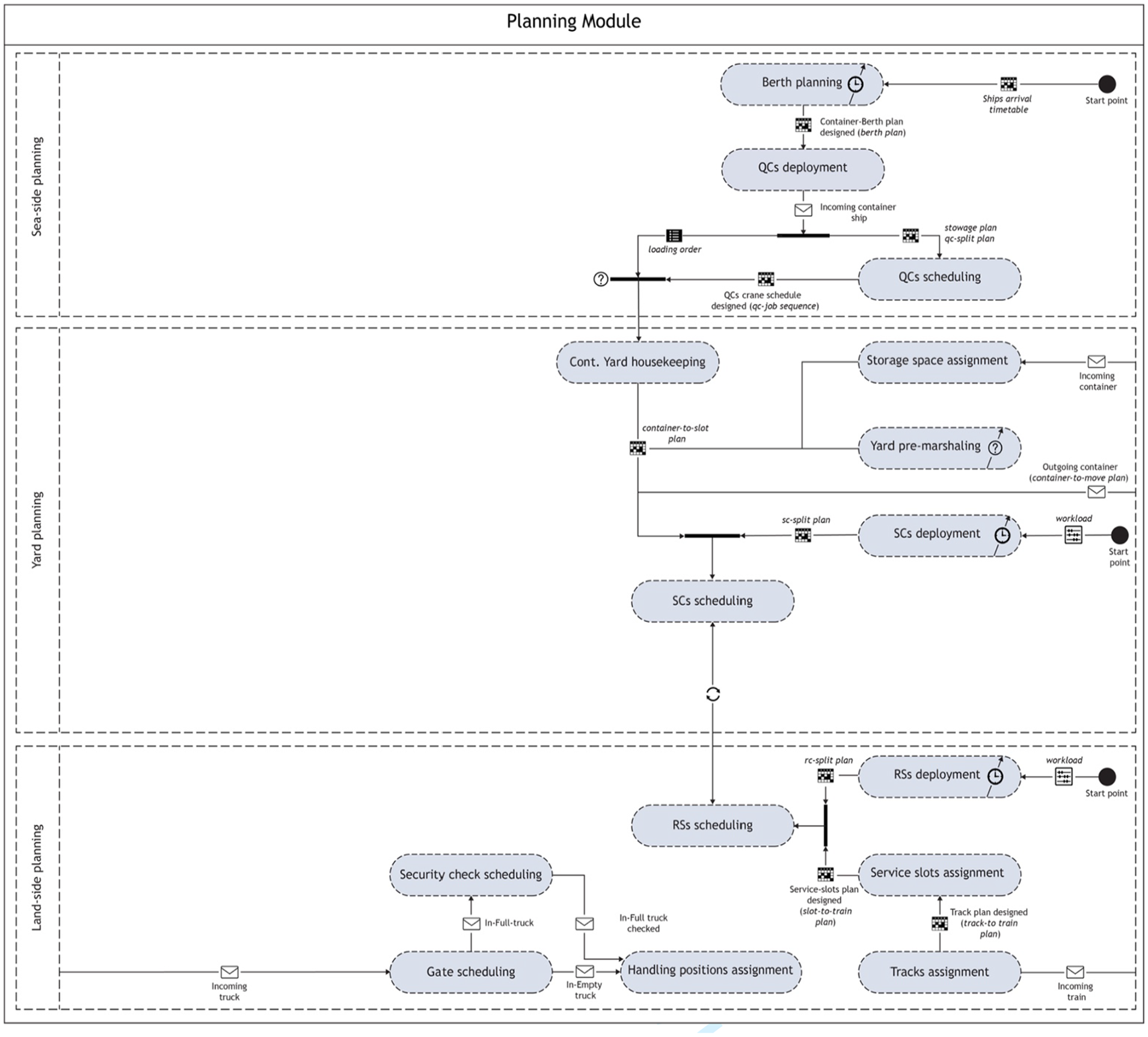
Planning module for Norvik port container terminal.
As can be seen from Figure 6, decisions are disposed following the zone to which they belong so as to give a realistic vision on real-system functioning. When transportation means are on the way to the port, either one by one they inform the planning module about their impending arrival or it is done by the TSP module (in case of sending arrival timetables). Then, the allocation of resources to the arriving means is carried out (berth, tracks, handling position, etc.) along with the assignment of storage slots to their transported containers. Afterward, the transportation means is assigned one or more handling equipment (equipment deployment), and once the equipment are designated, their moves are scheduled according to the given amount of workload to handle. Some decisions concern one particular mode, such as service slot assignment that decides on the handling slots of each train or each part of it. As for security check scheduling, it concerns the order of trucks to be inspected and their container checked. Container yard housekeeping is performed to arrange containers within the internal yard if necessary in a manner to minimize the stay of their outgoing ships. Yard pre-marshaling shares the same philosophy but for all modes when the internal yard is messy and the equipment are in their idle time.
Like the other modules, this module has a flexible design; it allows the addition of new decisions, the withdrawing of the not needed ones (e.g., container yard housekeeping, service slot assignment, etc.), and decisions merging (deployment with scheduling); however, the type of inputs and outputs must be respected.
4.5. Operating module
This module, as indicated by its name, simulates terminal operations, provides outcomes, and is the environment where evolve the items of resource module. Literature surveys on terminal operations, sub-systems, and layouts are given in: Stahlbock and Voß 11 and Steenken et al. 49 Operations can be classified into handling, maneuvering, and processing. Handling operations are three elementary functions: transfer (i.e., could be also named as unloading), storage, and transport. 50 Maneuvering is uncoupling, unberthing, and moving of wagons. Finally, processing concerns inspection and scanning of containers, gate operations, and maintenance of resource. On the basis of this, the operating module is built (see Figure 7).
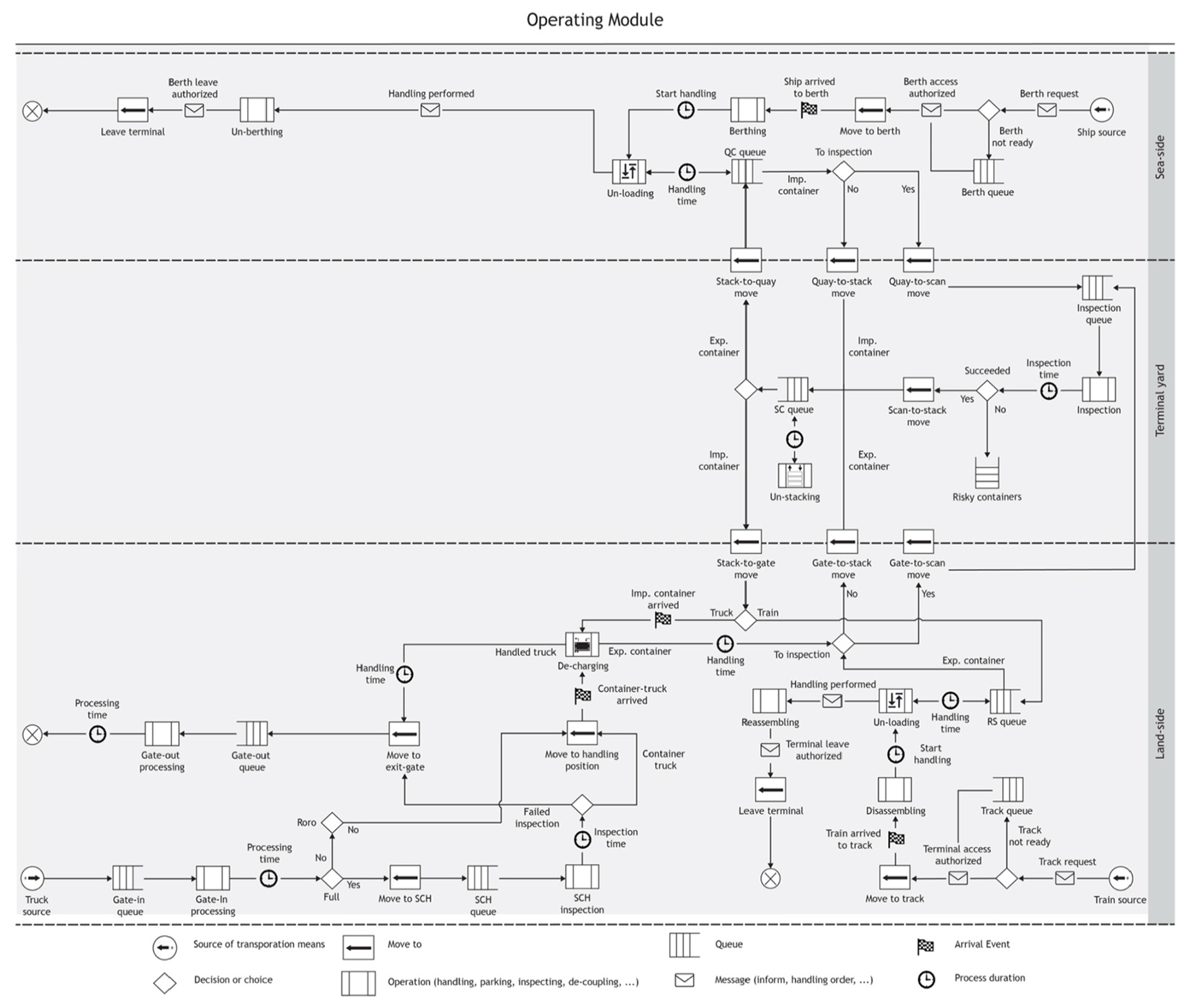
Operating module for Norvik port container terminal.
Figure 7 shows the one designed for the studied system. The operations are modeled as blocks linked by connectors to permit changes in the module structure; however, the types of entering and leaving agents via the connectors must be respected. As aforesaid, each operation takes place on infrastructural facilities and is executed by one or more actors, the whole ruled by a decision. This way of modeling is common in most known simulators for complex systems. There are other types of building blocks: namely, source, queue, and output choice. Queue is normally used to synchronize the access to the operation (could be also named process) while choice is for value evaluation and flow orientation. As concerns source, it is the connecting interface with TSP module.
As soon as a ship or train arrives to terminal, it asks for access authorization, and once approved if all allocated resources are ready to serve it, it enters the terminal and undergoes the I-O management operations (e.g., berthing, gate processing, train disassembling, etc.). Otherwise, it waits outside until the resources are available again. At the receiving yard, the train is decoupled from its locomotive and subdivided to a set of coupons (a part of train), then one by one and according to the pre-established plan, coupons are moved by an internal locomotive to the operating yard. Whereas, trucks arrive directly to the gate where their documentation and official papers are verified and the physical state of their transported containers is checked. When a transportation means arrives at its handling position (or transfer point), the handling operations start. Either the unloading comes before the loading or both are performed in parallel. Once unloaded, the container is routed to the yard to be stacked; conversely, containers to be loaded are moved from the yard to their outgoing means. During the retrieval, a reshuffling may happen if the container is inaccessible because of other ones blocking the way. Sometimes, false declarations of containers’ contents can be made to hide illicit freights intended to unlawful activities. To thwart such illegal activities, suspicious containers are identified (this decision could be added and called when the transport means arrive to terminal) and inspected by customs in a dedicated location within the port area using X-ray scanner and/or manual inspection. If it yields to positive inspection, the container is seized by customs. As early as the handling is over, the transport means leaves the terminal through the opposite manner of entering (unberthing, gate processing, train reassembling, etc.). Moreover, other risks are managed within the operating module, such as equipment interference, and truck-train collision, besides when bottlenecks or deadlocks situations emerged, the occurring location is highlighted and a warning is displayed. But, when an operational error happens like wrong assignment or planning, or saturation of resource, an exception is thrown.
Another interesting advantage in this conception is the possibility to simulate only operations at a specific zone while taking into account the handling times of the unconsidered operations. Indeed, all zones are connected by move-to blocks that could be used as black-box blocks to simulate handling operations in the background using estimation of times. It should be noted that these blocks ensure bi-directional moving of agents but for better visibility they are displayed as one-directional blocks. For example, one may wish to simulate visually only seaside operations, so the other blocks must be removed except those involved. Here, the transport equipment by the way of move-to blocks will move normally containers to the yard border, but the storage could be modeled as a timeout operation. Then, according to the operating plan of the equipment, the retrieval will be done in the same manner (i.e., move-to block acts like a loopback block).
4.6. Dashboard module
The role of this module is to express the quality of terminal operations in terms of comprehensible and meaningful quantitative indicators: the KPIs (key performance indicators). This module is based on the classification given by Kemme. 51
5. Model validation, experiments, and results
5.1. Model implementation
The obtained simulation model from the proposed architecture was implemented on AnyLogic simulation software 36 for the following reasons. First, AnyLogic supports all simulation techniques and equipped with a rich modeling toolbox that integrates most basic functions and probability distributions. Second, AnyLogic provides experiments to run simulations based on or coupled to optimization in different ways. Third, AnyLogic reduces the implementation time and efforts as no advanced programming skills are required. Finally, AnyLogic makes easier the expansion of the proposed architecture with further modeling blocks. Indeed, AnyLogic provides several modeling libraries (Process Modeling library, Road traffic library, Rail library, Pedestrian library, etc.) that contain well-known modeling blocks, namely, delay, seize, release, hold, and so on. These blocks could be used to expand the operating module to introduce further particular needs.
5.2. Conceptual model V & V
Since the conceptual model is the overpass to the implementation step, the V & V was conducted to ensure that the produced artifacts are reasonable and logical before proceeding to the implementation because being invalid leads to a waste of time and erroneous outputs. The straightforward way to validate and verify the conceptual models is examination by subject matter experts. 52 Also, on-the-spot visits to the real system are important to verify whether the collected knowledge and the retained hypotheses are correct or not. Such a way of V & V is widely used in gaming simulation.53,54 Both mentioned methods were used in this study. First, a visit was arranged to the container terminal of Norvik seaport. There, terminal planners and managers explained to us how every process works and what decisions are taken starting from the road-side operations until the seaside operations. Numerous obvious differences were then discerned in the first version of our models in comparison to the reality:
The entry and exit gates for trucks are not the same: in the models, we assumed that container trucks enter and leave, respectively, the terminal through the same gate.
Container trucks drive in reverse to access their handling positions (or transfer points): before entering the handling position in the handover area, trucks move first to a pre-entering space to be able to move backward.
SCs move containers from the railside after the end of train loading and unloading: SCs bring import containers to the railside before the arrival of trains and move the export ones when the RSs end the handling, contrary to our first assumptions where all of these operations are done simultaneously.
SCs enter and leave the transfer lanes in the quayside from specific distinct points: after observing how SCs work inside the quayside, it was noticed that SCs enter berths always from a side and leaving by the other side.
The established models and assumptions have been updated according to these observations and comments. To be certain about the validity of our models, they were presented to the experts, i.e., terminal planners, to be examined. The modeling logic of terminal processes as well as all agents and their individual behaviors were explained and examined, and the main comment was about the omission of human factor since a vehicle and its driver are considered as one unit. The reason behind that was exposed as modeling human behavior is so complicated, and it was rather modeled under the umbrella of probability of speeds and times which is the case in the majority of research. On the contrary, the structure of models was also discussed with the experts, i.e., how the system components were split, classified, and grouped (see section 4). They found it as an interesting way to represent the real system, and they were satisfied with the realized work.
5.3. Experiment and simulation scenarios
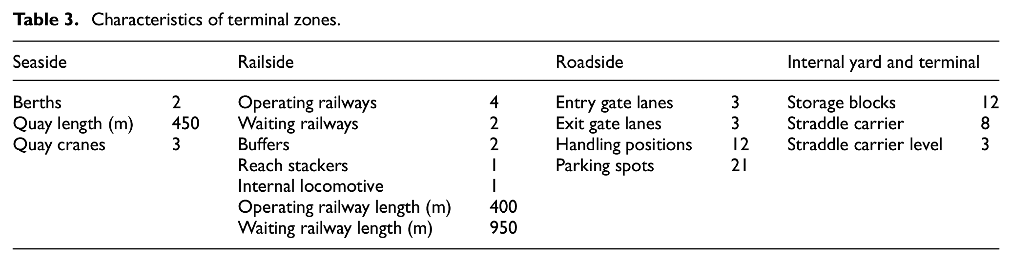
Using the designed simulation model, a numerical study was conducted to examine the handling capacity and performance of the studied system under multiple handling and flow scenarios. Thanks to the terminal operators, we obtained the empirical data about the expected container traffic during a typical year and the existing equipment fleets and layout (see Tables 2 and 3 and Figure 1). The terminal layout and equipment are supposed to serve a flow of 500,000 TEU per year which following the given data and the assumption that 70%–75% are FEU, the daily flow is estimated to be 800 ± 50 containers. The arrival rate and behavior of this flow were not provided, so to simulate the peaks during the day, three assumptions were made: peaks can happen either at start-day, at mid-day, or at end-day. This is to investigate the impact of arrival uncertainty on system behavior and resource (equipment and facilities). Moreover, to find out to what degree the terminal handling capacity could be expanded, the daily flow was increased by 100 boxes in each scenario with respect to layout constraints, i.e., additional facilities (berths, tracks, storage blocks, etc.) cannot be added. However, the capacity of infrastructural resource may not be considered entirely. For example, at the handover area there are 12 handling positions for trucks, but it is possible to start only with 8 of them (i.e., the remaining positions are omitted in the simulation), and then if it is insufficient, the remaining ones are reconsidered one by one. As concerns equipment, there are no constraints on the size of the fleets except for QCs, of which a maximum of two can be assigned to a berth. This helped us to determine the needed resource for ensuring an efficient and smooth evacuation of the different incoming flows.
Container traffic per year.
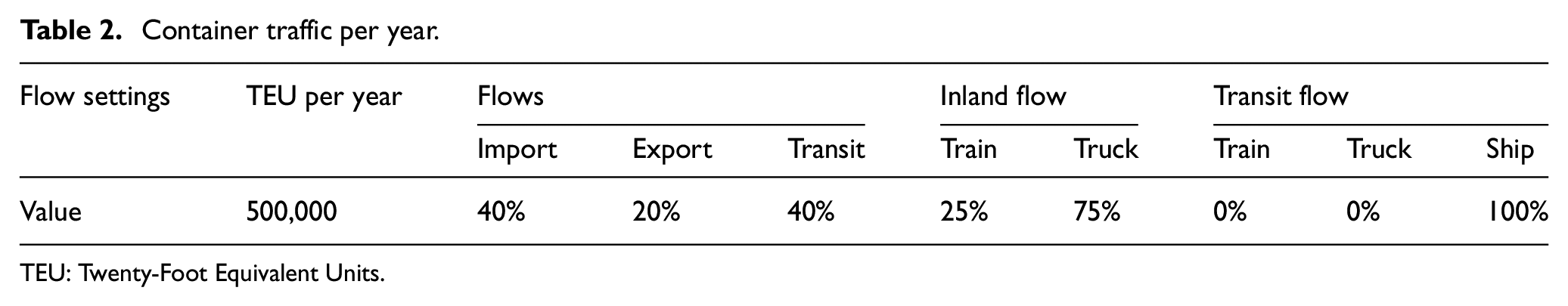
TEU: Twenty-Foot Equivalent Units.
Characteristics of terminal zones.
From the literature, 11 equipment and facilities could be either shared by all terminal sides (COMMON MODE) or each side can have its own equipment fleet and resource (DISTINCT MODE). In our terminal, this is applied on SCs and storage blocks at the yard. The synchronization of operations between equipment at the railside and seaside is of an important matter in the planning and scheduling of operations. At the seaside, two rules were applied: MANY-TO-MANY and MANY-TO-ONE. 11 The first one means that all SCs can work with all QCs, while the seconds means that a QC has its own servant fleet. Whereas, at the railside of our terminal, SCs and RSs work separately (SEPARATE), nevertheless, the opposite rule, i.e., SIMULTANEOUS rule also deserves attention in order to look at the benefits of such usage on operation performance and equipment utilization. The routing of SCs inside the terminal is managed by two strategies: SHORTEST PATH and CUSTOMIZED PATH. In the last strategy, the path is penalized by the utilization rate as follows:
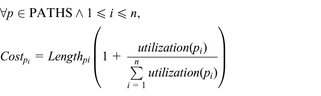
This means the more the path is used, the less it is chosen. The reason behind this is to avoid as much as possible the rapid damage of the shortest paths and to figure out the impact of choosing alternative paths on SCs’ utilization. To reduce the complexity of this experiment, the assignment of resource to askers and equipment scheduling are managed by nearest-available-one rule (this rule is considered as a standard rule by terminal planners).
The experiment study is conducted for seven working days (i.e., a week) as shown in Figure 8. In this experiment, the settings’ possible values (value range) for the main three modules are defined in the form of mapping lists (i.e., parameter: value range). The experiment starts with the TSP module that generates and injects the first flow scenario. The generated flows by TSP define the running number of the global loops. For every global loop, a set of middle loops are performed. These loops are linked to the planning module, where at each loop, one parameter is varied to indicate a new handling scenario. With regard to the operating module, it runs within a local loop called “iterations.” Since the simulation model is stochastic, the randomness is introduced at each iteration to vary speeds and times and size of considered resource pools. When the iterations are over, the outcomes are aggregated by the mean of averaging, then the experiment returns the local loop, and so on. The local loop ends when all the possible combinations of handling parameters are done. Afterward, the best handling scenarios are captured on the basis of the introduced objective function, then the next experimentation is launched, and so on. At the end, the obtained results can be discussed and evaluated by system experts, managers, and so on. With this experiment, planners can easily determine which solutions fit with their requirements and expectations about daily operational performance.
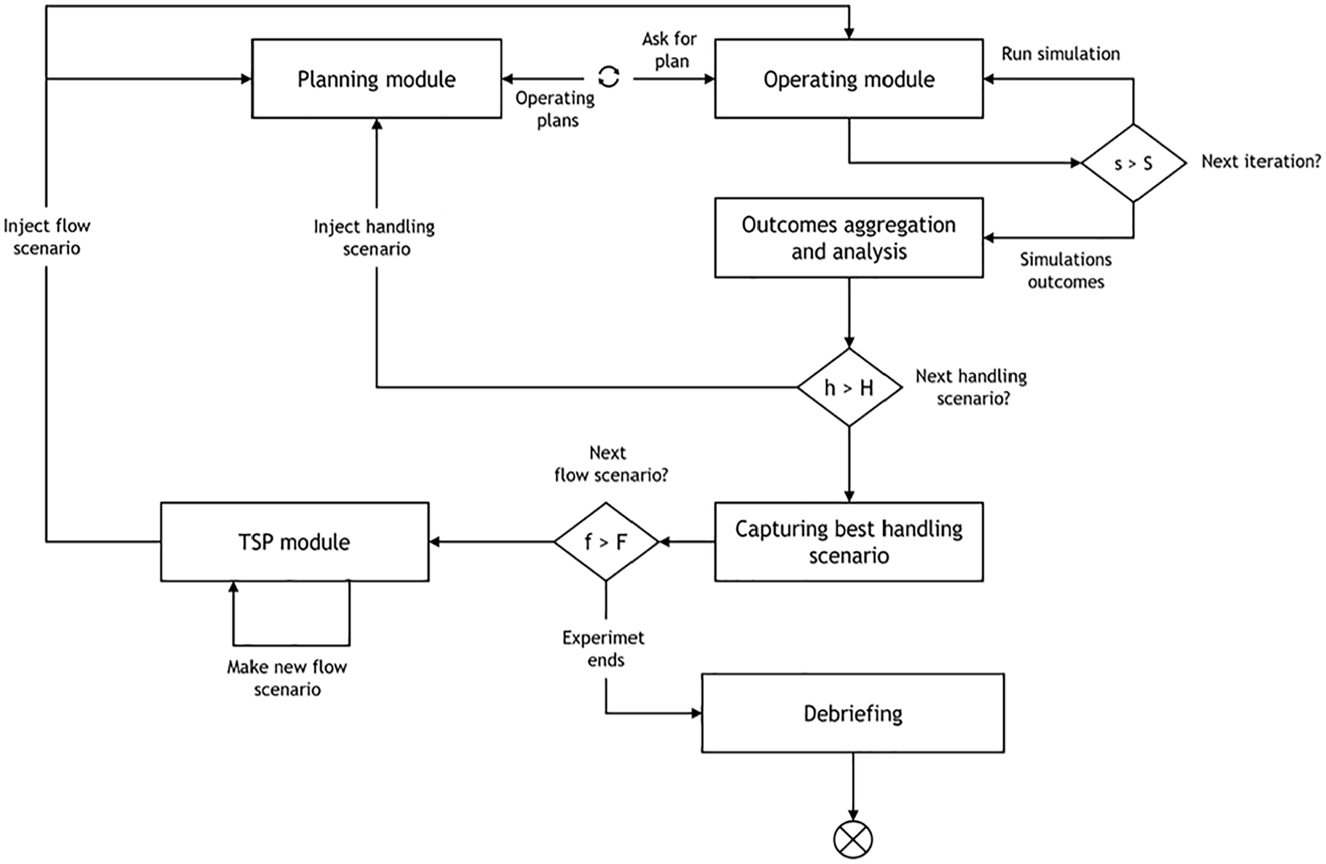
Experiment framework.
5.4. Simulation results and discussion
5.4.1. Replications and simulation model verification
Before going into the experiment, the simulation model needs to be verified and validated to prove that it is properly implemented and reflects the expected behavior as accurately as possible to be trustworthy. 52 The verification was done in three steps: model debugging, log-files checking, and three-dimensional (3D) animation visualization. The first two steps enabled us to trace the execution of simulation processes while the model was running in order to locate any dysfunctions. Next, the simulation in 3D animation was displayed in front of terminal managers so they can ensure that the terminal activities and operations are implemented in the right sequence as well as to check whether all agents (equipment and transport means) operate correctly or not.
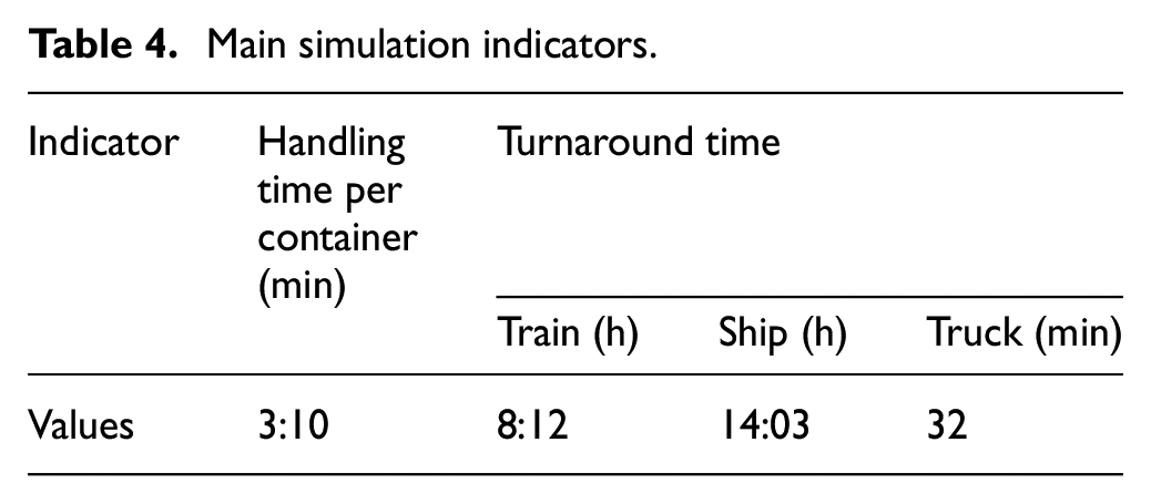
As for the validation, it was achieved through two steps. First, to check the accuracy of simulation outcomes, a number of replications were performed using the data set generated by TSP module based on Table 2. AnyLogic provides a Parameter Variation Experiment that stops replications after a minimum number of replications when the confidence level is reached. In the literature of port terminals, the confidence level is fixed at 95% and the error percentage is set as 0.05.41,55,56 In this study, the confidence level was constructed around the latest completion time of jobs. For our system, 10 replications were needed to achieve the required accuracy in the outputs. Usually, the second step is to compare simulation model outputs against the observed data in the real system which unfortunately are unavailable for us now because the Norvik seaport has recently opened its doors. The alternative is then to discuss the obtained outputs with terminal planners and managers, so they can assess the degree of output validity according to their experience. The discussion was mainly about two indicators: average handling time per container and average turnaround time per transport means (see Table 4). For the panel of experts, the reported values seem reasonable and logical to their minds. In addition, according to the literature, the average handling time per container should be around (or less than) 3 min.
Main simulation indicators.
5.4.2. Results and system analysis
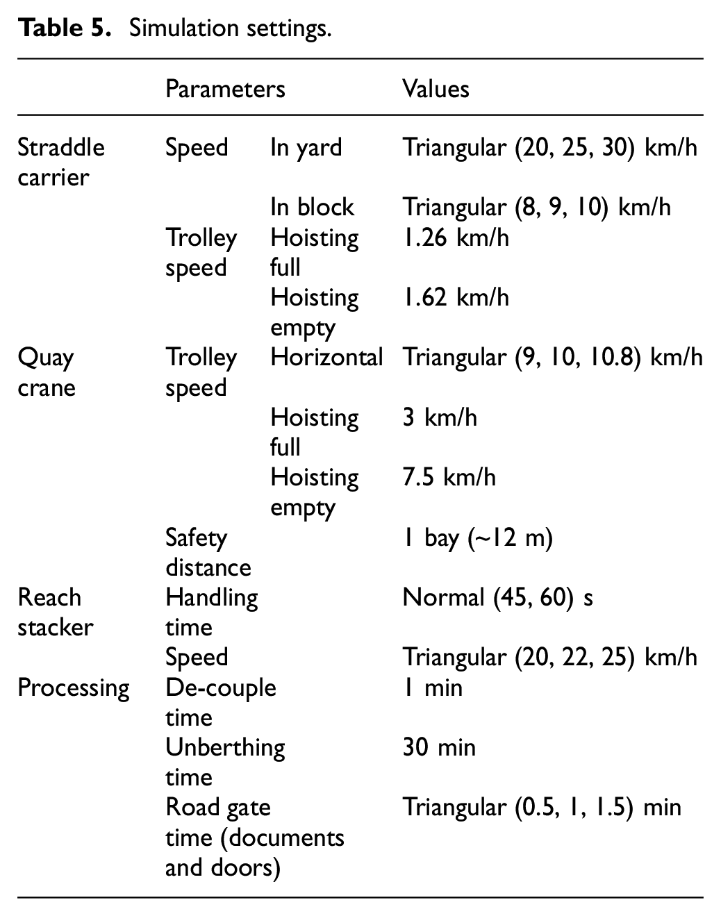
The simulation model was run using the settings displayed in Table 5. These data were collected from the paper of Cartenì and de Luca, 31 technical specifications of equipment and real observation. Figures 9 and 10 show the difference between DISTINCT and COMMON modes in terms of resource utilization and needed fleet size. Figures 11 and 12 report the needed resource to serve efficiently trucks and their usage over time, incoming flows, and used routing strategy. While Figures 13 and 14 describe the impact of routing strategy on SC utilization and the impact of resource availability on truck activity, respectively. Likewise, but for the railside, Figures 15 and 16 indicate the gap between the SC-RS synchronization rules for resource utilization and train activity. As regards the seaside, the impact of SC-TO-QC assignment rules is illustrated in Figures 17 and 18.
Simulation settings.
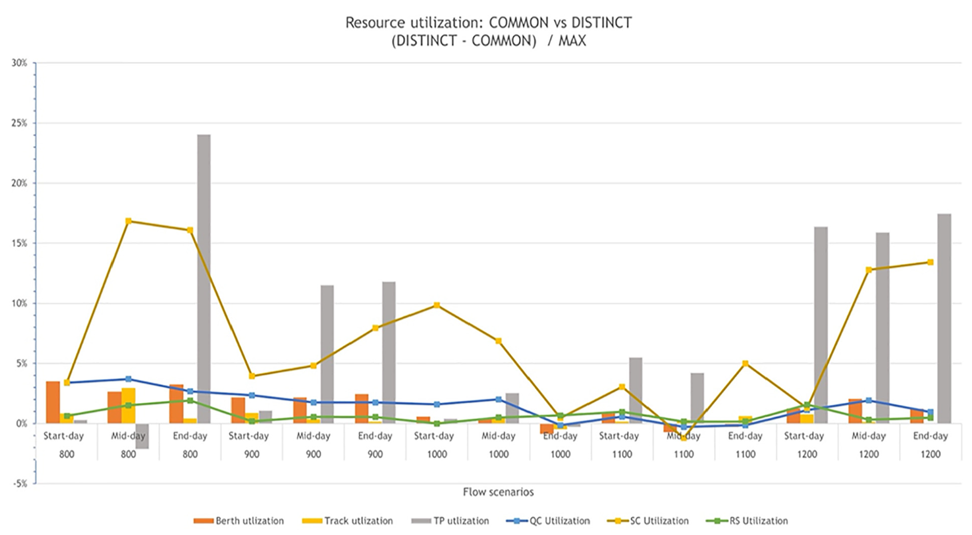
Resource utilization gap: COMMON versus DISTINCT.
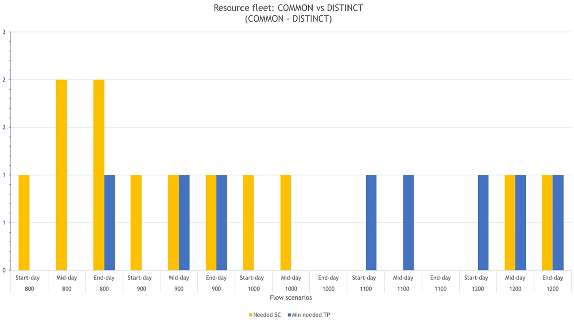
Resource fleet gap: COMMON versus DISTINCT.
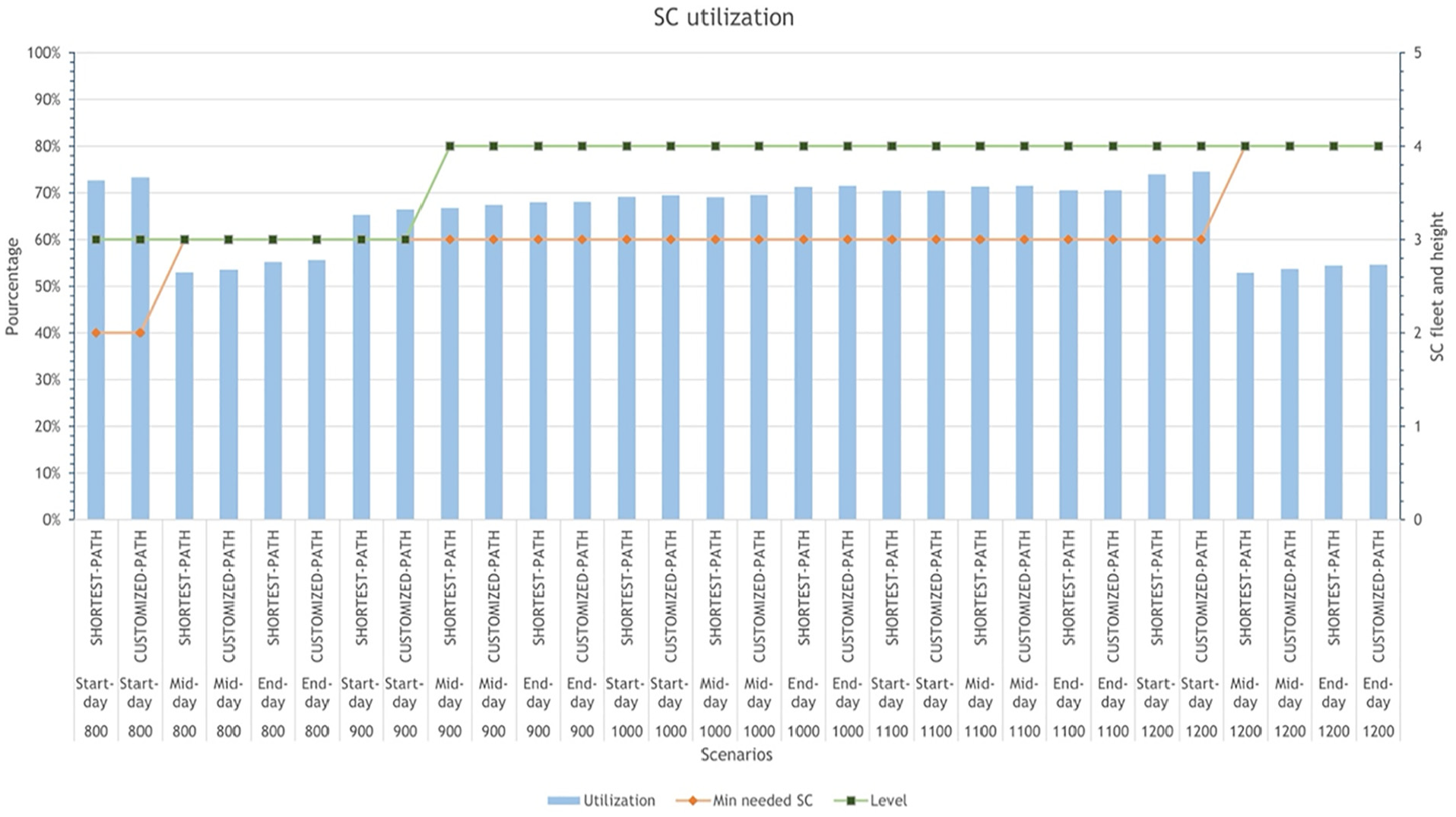
SC utilization at roadside.
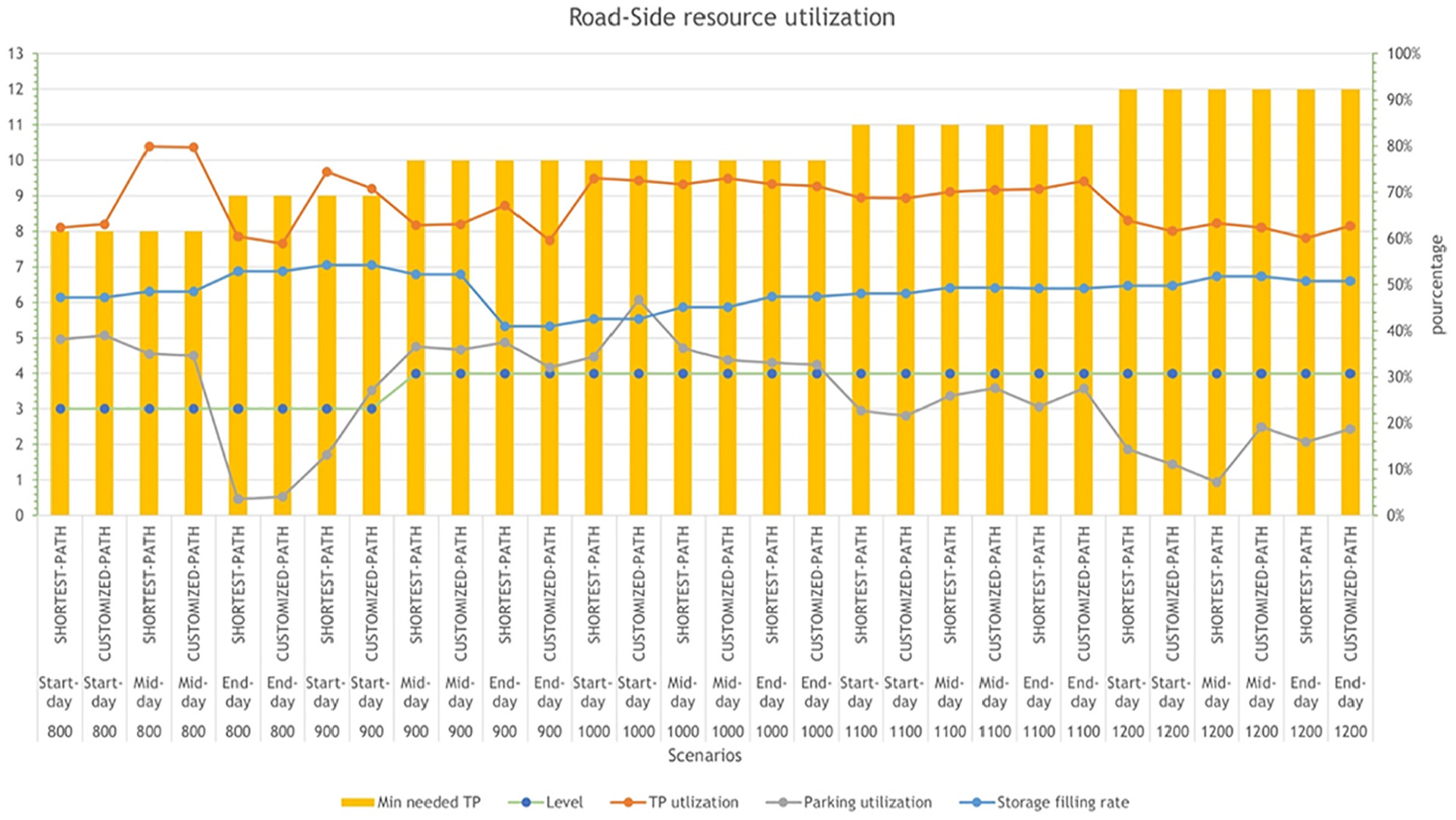
Resource utilization at roadside.
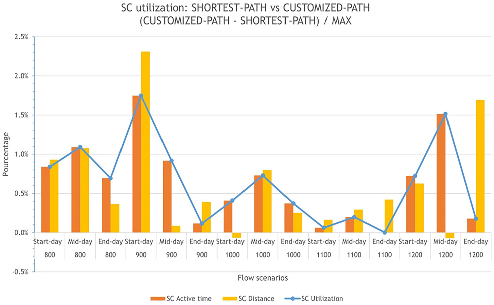
SC utilization gap: SHORTEST PATH versus CUSTOMIZED PATH.
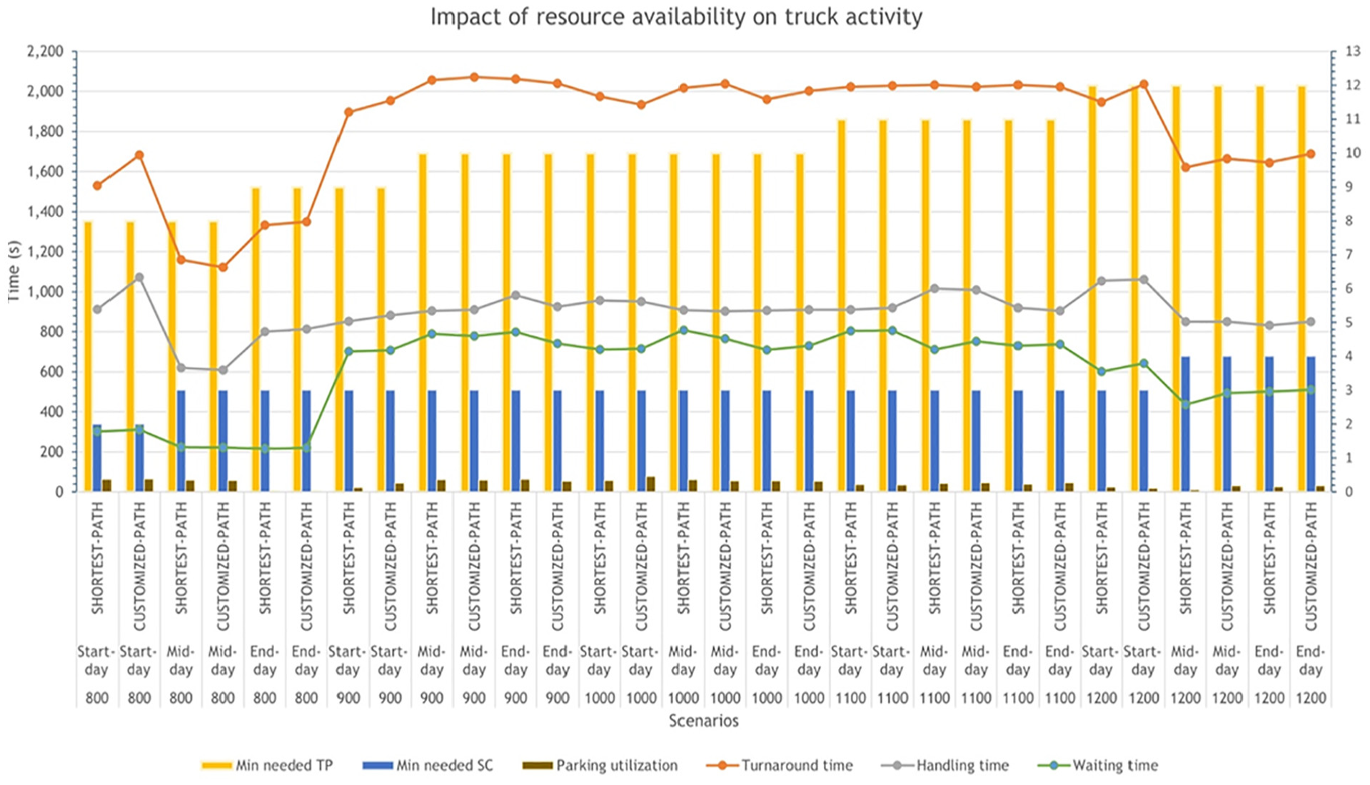
Truck activity: impact of resource availability at roadside.
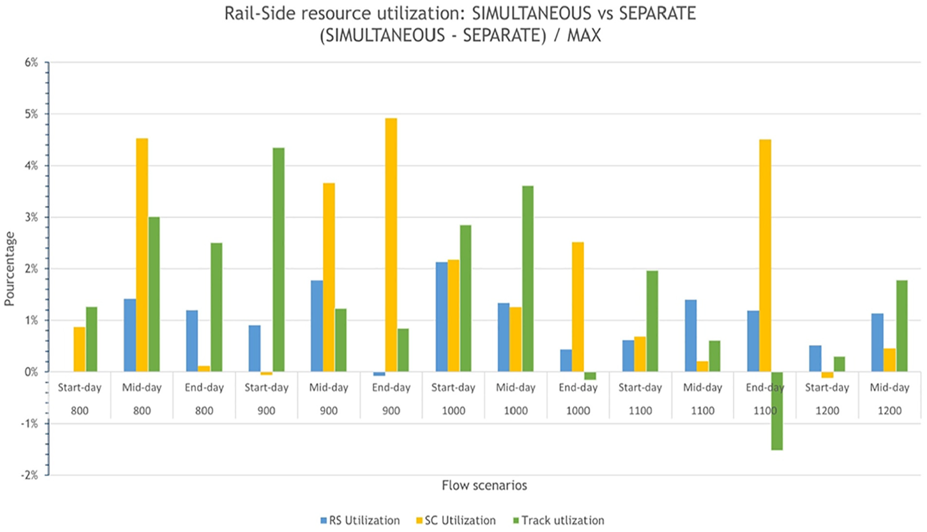
Resource utilization gap at railside: SIMULTANEOUS versus SEPARATE.
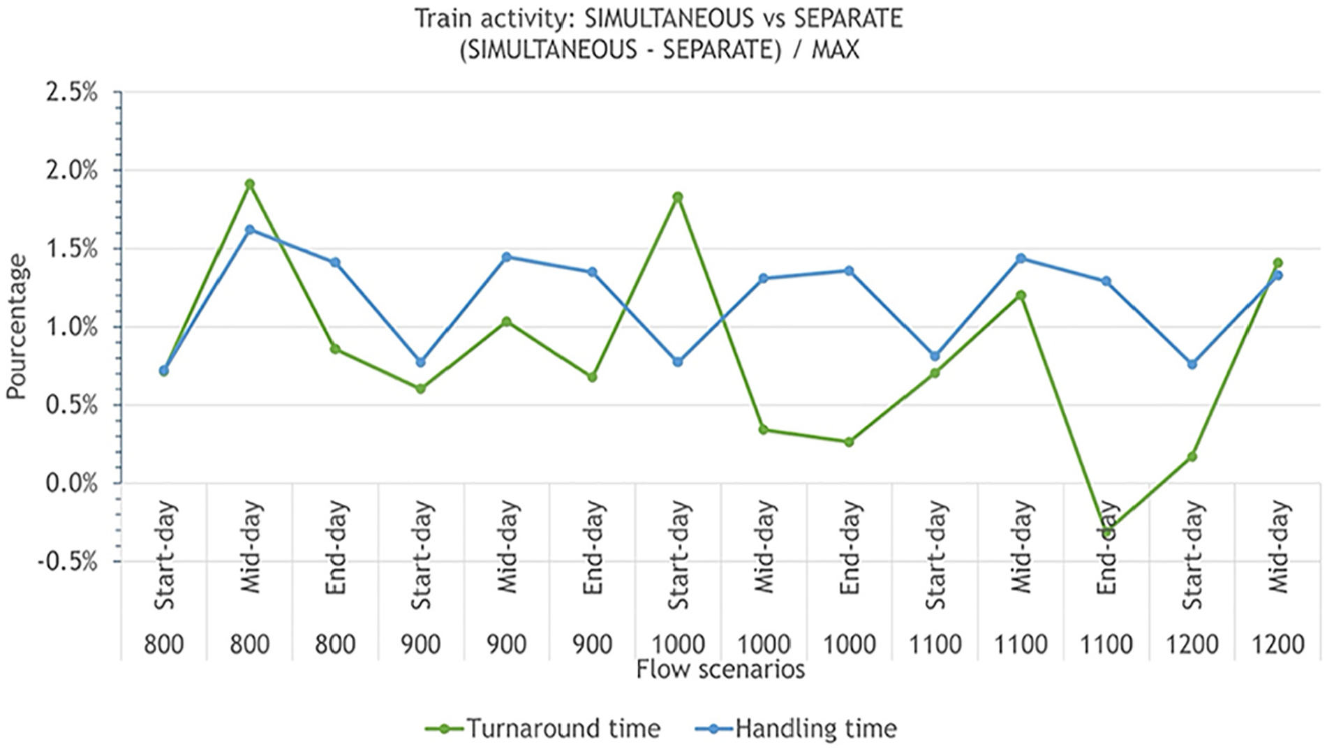
Train activity gap: SIMULTANEOUS versus SEPARATE.
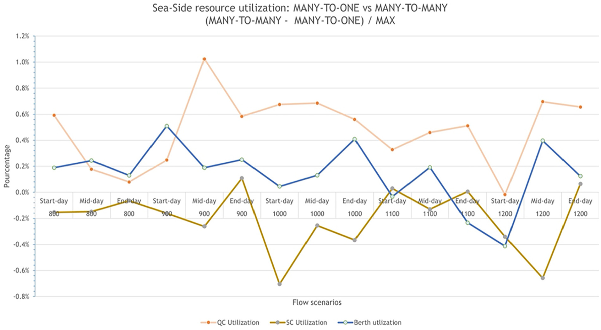
Resource utilization gap at seaside: MANY-TO-ONE versus MANY-TO-MANY.
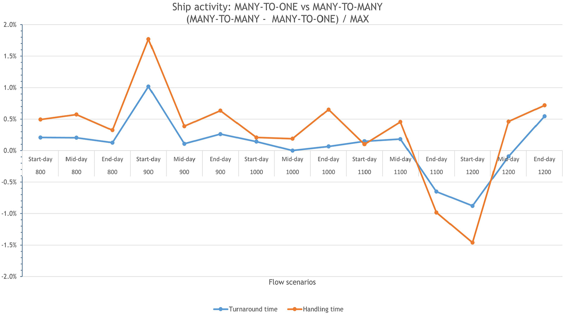
Ship activity gap: MANY-TO-ONE versus MANY-TO-MANY.
The obtained results showed that the terminal handling capacity can be expanded to around 50% (∼1200 containers per day) if three (in total 11 SCs) or four (in total 12 SCs) more SCs are considered (this depends on the used sharing strategy: three in COMMON mode and four in case of DISTINCT mode), all of them able to construct four-container stacks (four-level stack), in addition to one more RS (in total two RSs). The existing QCs fleet seems adequate to handle the incoming flow in all scenarios under the considered assumptions. Theoretically, a QC can make 26 moves (either to load or unload) per hour, i.e., three QCs are able to handle more than 1200 containers per day. But in general, the handling capacity is more related to the storage yard capacity.
However, from the explained figures above, we can note that there is only a slight difference between the evaluated rules and strategies, except for the usage of SCs and handover area in DISTINCT and COMMON modes where the gap nearly reaches 25%. This is because the second one uses less resource (see Figure 10) so logically the utilization will increase. Indeed, SCs have freedom to move around the terminal, so they can reply more quickly to handling requests, especially those coming from trucks; consequently, trucks leave the terminal faster and less handling positions (or transfer points) are required. However, the planning and scheduling under COMMON mode is more complicated. 11 Moreover, no changes were noticed in the required fleet of QCs and RSs and the used rail tracks at the railside. In all scenarios, three QCs (with utilization between 66% and 73%) have been used. One of the reasons behind such finding is that, in reality, QCs have priority over SCs (i.e., in case of interference, SCs wait for QCs until they finish, not the opposite) which means that QCs will have less waiting time and their productivity is improved, i.e., better usage. Regarding the railside, since little traffic arrives and leave by rail (∼15%) as well as the workload is grouped in a small area, only two RSs (with utilization between 46% and 63%) and two operating rail tracks (with utilization between 47% and 67%) were needed to handle all flows.
As can be seen from Figures 11, 12, and 14, the handling processes at the roadside are heavily influenced by the size of SC fleet and the capacity of the handover area. When the number of SCs has increased the truck turnaround and handling times is decreased, which minimizes the time that truck spent at the parking area. The waiting time of trucks can be also reduced (i.e., parking utilization reduced) if more transfer points are available which, of course, will enable terminal to avoid external queues, but the handling time of trucks will be increased (time that trucks stay at the handover area). That is, increasing handover area capacity does not literally lead to enhance effectively truck activity. Therefore, we can deduce that SC planning and scheduling define the level of service provided to trucks. In addition, road-side outputs reveal also that morning peaks require less SCs since SCs have more time to manage it and to complete their work on time (see Figure 11), besides the maximum utilization (critical point) of a resource should be less than 80% otherwise it is considered as overused and queues of transportation means, particularly trucks, outside the terminal could be formed and such situation needs to be avoided to keep the terminal competitivity at high level (see Figures 11 and 12). With regard to the routing strategy, it is clear from Figure 13, how low is its impact, i.e., around 2.5% on the driven distance. This can be explained by the fact that in the CUSTOMIZED strategy shortest paths still have a lower cost than the longest ones even if they are penalized with huge utilization since the penalty is based on the length. Furthermore, in the terminal, there are multiple paths with the same length.
As for railside and seaside activities, they are linked to RSs and QC performance, respectively (see Figures 15 –18). The advantage of using the SEPARATE rule is confirmed as the utilization of resources is minimized while avoiding additional waiting situations between SCs and RSs that are caused by SIMULTANEOUS rule (see Figures 15 and 16). This enables equipment to perform more jobs and to speed up container processing on trains so more coupons could be handled, nevertheless the late completion time of operations is longer because SCs and RSs wait until the others finish working before starting their own workload. Conversely, this is the advantage of SIMULTANEOUS rule where equipment end their workload earlier since containers are often available in advance at the rail buffers. Since only a small flow goes through the railside, the arrival rate has no significant impact on handling operation.
In Figure 17, MANY-TO-ONE appears to be beneficial to QCs while with MANY-TO-MANY SCs can improve their productivity as they gain in time in serving QC with the most urgent task; however, it is very complicated to set up. 11 Furthermore, the most important performance indicator is the time that ships spent at the terminal, i.e., the less the turnaround time, the more the terminal attractiveness, i.e., why MANY-TO-ONE rule is more appropriate to meet such aim. Indeed, with MANY-TO-ONE, QCs have less waiting time for SCs (each QC has its own SC servants) which enables them to handle more faster containers on ships (see Figure 18). Another inconvenience of MANY-TO-MANY but observed in the simulation is the congestion that happens when more than three SCs reply to handling requests of the same QC and this increases both waiting time of SCs and QCs. To sum up, it is better to assign equipment to a specific side and role within the terminal in order to work smoothly with less congestion and to evacuate more efficiently containers to their destination.
5.4.3. Architecture scalability and limitations
The studied system in this paper is actually containing most of container terminals operations, namely, seaside operations, yard operations, road-side operations, and railside operations and through the showed models the main commonalities and variabilities are displayed. For instance, the designed items for the railside could be used to represent a pure rail–rail trans-shipment terminal as follows:
TSP module: here, specify which types of transport mode (in this case, trains) will deliver and collect the expected daily flow of containers using the Enums Flow, Size, Type, and TransportMode and the class ContainerFlow, finally build the arrival timetable for each category using the class TransportModeScheduler and the Enum TransportMode.
Resource module: here, define the agents representing the considered equipment and the transport means (i.e., Container, Wagon, Locomotive, Train, and RailGantry) as well as the needed infrastructural resource (i.e., RailNetwork, StackBlock, Stack, ComposedResource, and SimpeResource).
Planning module: here, keep only the needed decisions to rule and manage the considered equipment and facilities, which are, RailGantry scheduling and deployment, Storage space assignment, Tracks assignment, and Service slots assignment.
Operating module: here, keep only the blocks representing rail–rail trans-shipment operations, which are, Train source, Disassembling, Reassembling, Move to track, and Unloading for trains (unloading of trains also includes the storage and retrieval of containers from the storage area).
Dashboard module: here, specify the KPIs related to rail–rail trans-shipment operations.
Likewise, if the road-side items are included, models for a rail–road container terminal could be obtained. To get modules for a pure vessel-to-vessel trans-shipment terminal, items of rail and roadsides must be removed. As concerns barges, they have the same items of ships except for equipment where usually gantry cranes are used instead of QCs. Moreover, one typical problem with barges is that the barge schedule is a by-product of the main vessel schedule. Unless there is enough berth availability, barges are accommodated during the schedule gaps. All of these changes must respect the type of inputs, outputs, and relationships between items to maintain the goodness of fit of the whole system. As can be seen, the presented architecture is easily manageable and scalable for the most known container terminal types. Also, this architecture can be seen as a modeling technique and approach to building specific models for container terminals where the user has the freedom to implement it as he sees fit.
It is also worth noting that the proposed framework could also be applied to Ro-Ro terminals given the similarities that they have with container terminals. An application of this architecture to Ro-Ro terminals is given in Abourraja et al. 57 This framework could be also adjusted to inland ports or other complex systems; but we believe that this depends on how close they are, both functionally and physically, to the studied system in this paper.
Despite this scalability, some limitations of the architecture are worth noting:
Human factor: in this study, equipment drivers are not explicitly considered so that to reduce system complexity; in addition, our interest was in the planning and management of equipment and not in by which person they are driven.
Special layout and vehicles: the automated storage and retrieval system (AS/RS) for containers, 11 the overhead grid system for container storage, 16 and the self-unloading trucks are not considered because either they are rarely used or they are just a concept.
6. Conclusion
This paper introduced a novel generic architecture to build modular and flexible simulation-based decision support for container terminals. It contains five main modules and a helpful mechanism to determine which solutions fit with the fixed requirements and expectations about daily operational performance. The architecture provides high flexibilities in developing simulation models for various types of containers terminals as well as in expanding and extending certain of its modules to capture more particular requirements, as demonstrated in the use case for a new harbor in Stockholm. However, the human factor is not explicitly represented, and some special layouts and equipment are not considered which appear as an improvement for our architecture in the future. The architecture was illustrated through a case study and the resulting models were validated by subject matter experts. A numerical study was conducted to analyze system performance and the main conclusions are drawn as follows: the split of resource on terminal sides is advantageous at the operational level but requires more resource as well as the handling capacity can be increased by around 50% if three or four more SCs are considered. This shows that the established simulation model can be helpful in making sound decisions about daily operations.
Unfortunately, other types of seaport terminals, such as dry bulk and liquid bulk terminals, are not supported by this framework because in this study the spotlight was only on ITU terminals (ITU: an intermodal transport unit is a loading unit used in intermodal transport, namely, containers, lorries, and trailers) such as container and pure Ro-Ro terminals. At first sight, these kinds of terminals used different types of equipment (for instance, pipelines), but the functioning is quite close to that of ITU terminals. This direction, therefore, is worth investigating to expand our framework to cover other port terminals and facilities.
Further remarks and suggestions are worth noting: using yard cranes or rail mounted gantries instead of SCs will increase the handling capacity and throughput of the internal yard as well as using rail cranes instead of RSs will increase the throughput of the railside. As future works, we plan to study deeply operational problems one by one starting with the seaside, then move to the next side with relation to the studied ones in view of integrating optimization or other performing models in our simulation model. Another future challenge is to implement the proposed architecture as an AnyLogic library. This because AnyLogic provides a very rich modeling libraries (Process Modeling library, Road traffic library, Rail library, Pedestrian library, etc.) that contains well-known modeling blocks, namely, delay, seize, release, hold, and so on which could be used to easily expand the presented architecture.
Footnotes
Acknowledgements
The authors thank all stakeholders, particularly from Ports of Stockholm for their inputs. The authors greatly appreciate the time and efforts by the editor and referees in reviewing this manuscript and the insightful comments and thoughtful suggestions provided by each reviewer. This article is based upon work done under the ELISA project (Energy-effective Logistics and Infrastructure Systems Assessment for Cargo Ports), financed by the Swedish Energy Agency.
Funding
This research received no specific grant from any funding agency in the public, commercial, or not-for-profit sectors.